EP1100628B1 - Off-aperture electrical connection for ultrasonic transducer - Google Patents
Off-aperture electrical connection for ultrasonic transducer Download PDFInfo
- Publication number
- EP1100628B1 EP1100628B1 EP99933066A EP99933066A EP1100628B1 EP 1100628 B1 EP1100628 B1 EP 1100628B1 EP 99933066 A EP99933066 A EP 99933066A EP 99933066 A EP99933066 A EP 99933066A EP 1100628 B1 EP1100628 B1 EP 1100628B1
- Authority
- EP
- European Patent Office
- Prior art keywords
- washer
- transducer
- transducer element
- matching layer
- imaging assembly
- Prior art date
- Legal status (The legal status is an assumption and is not a legal conclusion. Google has not performed a legal analysis and makes no representation as to the accuracy of the status listed.)
- Expired - Lifetime
Links
- 238000003384 imaging method Methods 0.000 claims description 54
- 239000000463 material Substances 0.000 claims description 39
- 239000004020 conductor Substances 0.000 claims description 22
- 239000000853 adhesive Substances 0.000 claims description 15
- 230000001070 adhesive effect Effects 0.000 claims description 15
- 238000004891 communication Methods 0.000 claims description 13
- 239000012811 non-conductive material Substances 0.000 claims description 10
- 239000004642 Polyimide Substances 0.000 claims description 5
- 229920001721 polyimide Polymers 0.000 claims description 5
- 239000010410 layer Substances 0.000 description 93
- 239000004593 Epoxy Substances 0.000 description 14
- 238000002604 ultrasonography Methods 0.000 description 9
- 230000000712 assembly Effects 0.000 description 6
- 238000000429 assembly Methods 0.000 description 6
- BQCADISMDOOEFD-UHFFFAOYSA-N Silver Chemical compound [Ag] BQCADISMDOOEFD-UHFFFAOYSA-N 0.000 description 5
- 229910052709 silver Inorganic materials 0.000 description 5
- 239000004332 silver Substances 0.000 description 5
- RYGMFSIKBFXOCR-UHFFFAOYSA-N Copper Chemical compound [Cu] RYGMFSIKBFXOCR-UHFFFAOYSA-N 0.000 description 4
- 229910000831 Steel Inorganic materials 0.000 description 4
- 239000012790 adhesive layer Substances 0.000 description 4
- 229910052802 copper Inorganic materials 0.000 description 4
- 239000010949 copper Substances 0.000 description 4
- 238000000034 method Methods 0.000 description 4
- 229910001220 stainless steel Inorganic materials 0.000 description 4
- 239000010935 stainless steel Substances 0.000 description 4
- 239000010959 steel Substances 0.000 description 4
- 238000012285 ultrasound imaging Methods 0.000 description 4
- 230000000644 propagated effect Effects 0.000 description 3
- 229920002799 BoPET Polymers 0.000 description 2
- VYZAMTAEIAYCRO-UHFFFAOYSA-N Chromium Chemical compound [Cr] VYZAMTAEIAYCRO-UHFFFAOYSA-N 0.000 description 2
- 239000005041 Mylar™ Substances 0.000 description 2
- PXHVJJICTQNCMI-UHFFFAOYSA-N Nickel Chemical compound [Ni] PXHVJJICTQNCMI-UHFFFAOYSA-N 0.000 description 2
- 230000008901 benefit Effects 0.000 description 2
- 230000005540 biological transmission Effects 0.000 description 2
- 238000013461 design Methods 0.000 description 2
- 229920001971 elastomer Polymers 0.000 description 2
- PCHJSUWPFVWCPO-UHFFFAOYSA-N gold Chemical compound [Au] PCHJSUWPFVWCPO-UHFFFAOYSA-N 0.000 description 2
- 229910052737 gold Inorganic materials 0.000 description 2
- 239000010931 gold Substances 0.000 description 2
- 229910052751 metal Inorganic materials 0.000 description 2
- 239000002184 metal Substances 0.000 description 2
- 238000012986 modification Methods 0.000 description 2
- 230000004048 modification Effects 0.000 description 2
- 239000004033 plastic Substances 0.000 description 2
- 229920003023 plastic Polymers 0.000 description 2
- 229920002635 polyurethane Polymers 0.000 description 2
- 239000004814 polyurethane Substances 0.000 description 2
- 239000005060 rubber Substances 0.000 description 2
- 239000007787 solid Substances 0.000 description 2
- 239000000758 substrate Substances 0.000 description 2
- WFKWXMTUELFFGS-UHFFFAOYSA-N tungsten Chemical compound [W] WFKWXMTUELFFGS-UHFFFAOYSA-N 0.000 description 2
- 229910052721 tungsten Inorganic materials 0.000 description 2
- 239000010937 tungsten Substances 0.000 description 2
- 229910001369 Brass Inorganic materials 0.000 description 1
- 239000004677 Nylon Substances 0.000 description 1
- 239000004698 Polyethylene Substances 0.000 description 1
- 239000002313 adhesive film Substances 0.000 description 1
- 230000002411 adverse Effects 0.000 description 1
- 210000003484 anatomy Anatomy 0.000 description 1
- 210000004204 blood vessel Anatomy 0.000 description 1
- 239000010951 brass Substances 0.000 description 1
- 230000008878 coupling Effects 0.000 description 1
- 238000010168 coupling process Methods 0.000 description 1
- 238000005859 coupling reaction Methods 0.000 description 1
- 230000000593 degrading effect Effects 0.000 description 1
- 239000012530 fluid Substances 0.000 description 1
- 229910052759 nickel Inorganic materials 0.000 description 1
- 229920001778 nylon Polymers 0.000 description 1
- -1 polyethylene Polymers 0.000 description 1
- 229920000573 polyethylene Polymers 0.000 description 1
- 238000012545 processing Methods 0.000 description 1
- 229910000679 solder Inorganic materials 0.000 description 1
- 125000000391 vinyl group Chemical group [H]C([*])=C([H])[H] 0.000 description 1
- 229920002554 vinyl polymer Polymers 0.000 description 1
- 238000003466 welding Methods 0.000 description 1
Images

Classifications
-
- B—PERFORMING OPERATIONS; TRANSPORTING
- B06—GENERATING OR TRANSMITTING MECHANICAL VIBRATIONS IN GENERAL
- B06B—METHODS OR APPARATUS FOR GENERATING OR TRANSMITTING MECHANICAL VIBRATIONS OF INFRASONIC, SONIC, OR ULTRASONIC FREQUENCY, e.g. FOR PERFORMING MECHANICAL WORK IN GENERAL
- B06B1/00—Methods or apparatus for generating mechanical vibrations of infrasonic, sonic, or ultrasonic frequency
- B06B1/02—Methods or apparatus for generating mechanical vibrations of infrasonic, sonic, or ultrasonic frequency making use of electrical energy
- B06B1/06—Methods or apparatus for generating mechanical vibrations of infrasonic, sonic, or ultrasonic frequency making use of electrical energy operating with piezoelectric effect or with electrostriction
- B06B1/0644—Methods or apparatus for generating mechanical vibrations of infrasonic, sonic, or ultrasonic frequency making use of electrical energy operating with piezoelectric effect or with electrostriction using a single piezoelectric element
- B06B1/0662—Methods or apparatus for generating mechanical vibrations of infrasonic, sonic, or ultrasonic frequency making use of electrical energy operating with piezoelectric effect or with electrostriction using a single piezoelectric element with an electrode on the sensitive surface
- B06B1/067—Methods or apparatus for generating mechanical vibrations of infrasonic, sonic, or ultrasonic frequency making use of electrical energy operating with piezoelectric effect or with electrostriction using a single piezoelectric element with an electrode on the sensitive surface which is used as, or combined with, an impedance matching layer
-
- A—HUMAN NECESSITIES
- A61—MEDICAL OR VETERINARY SCIENCE; HYGIENE
- A61B—DIAGNOSIS; SURGERY; IDENTIFICATION
- A61B8/00—Diagnosis using ultrasonic, sonic or infrasonic waves
- A61B8/44—Constructional features of the ultrasonic, sonic or infrasonic diagnostic device
- A61B8/4483—Constructional features of the ultrasonic, sonic or infrasonic diagnostic device characterised by features of the ultrasound transducer
- A61B8/4494—Constructional features of the ultrasonic, sonic or infrasonic diagnostic device characterised by features of the ultrasound transducer characterised by the arrangement of the transducer elements
Definitions
- the present invention relates generally to ultrasonic imaging catheters, and more particularly, to catheters having improved electrical connections for ultrasonic transducers.
- Intravascular imaging of blood vessels and surrounding tissues continues to be of great benefit in a wide range of medical fields.
- a particularly successful design for an intravascular imaging catheter employs a rotatable imaging assembly containing an ultrasonic transducer, where the assembly is attached to the distal end of a flexible drive cable.
- the transducer may be rotated within a catheter body or sheath in order to transmit an ultrasonic signal and produce a video image by well-known techniques.
- the transducer element or elements are connected to electronics, typically maintained outside the patient's body, to produce the video image.
- an electrode or lead typically is physically attached to either the transducer face, or to the face of a matching layer which is, in turn, attached to the transducer face.
- an attachment e.g., a soldered silver attachment point
- the attachment interferes with or blocks at least part of the transmitted and/or reflected signals. This problem is further exacerbated by the fact that such attachments often are made by hand. Attachments made by hand typically vary in both size and location from catheter to catheter. As a result, it can be difficult to predict the amount of interference the attachment will produce for a particular imaging catheter.
- the placement and attachment of the transducer onto the imaging assembly likewise presents difficulties. For example, it often is desirable to attach the transducer element to the imaging assembly so that the element is positioned at a certain angle, or a desired offset, with respect to the assembly centerline. For transducers that are placed and affixed by hand, the angle and offset can vary between otherwise identical catheters.
- JP 07322393 discloses a transducer arrangement comprising a variable thickness metal matching layer, one surface of which is connected to a transducer and the sides ofwhich are connected to a metal vessel.
- connections of the present invention are intended to overcome of at least alleviate at least some of the problems of the prior art.
- connections of the present invention move the electrode or front lead attachment off-aperture, or off the transducer face. This reduces or eliminates the interference such attachment points may cause to the ultrasound signals transmitted from and/or received by the transducer element.
- imaging assemblies of the present invention are designed to reduce or eliminate the catheter-to-catheter variations in the transducer's offset and angular position with respect to the assembly housing centerline. Such assemblies are hence more uniform and predictable.
- the electrical connection is made with a reduced concern as to the size or precise location of the attachment point because the lead is attached to the washer and not to the transducer or matching layer face.
- the matching layer includes a material having an acoustic impedance that is lower than an impedance of the transducer element.
- a matching layer is particularly useful since transducer elements typically have a significantly higher impedance than an impedance of the surrounding tissue being imaged.
- the matching layer includes an electrically conductive material. In this manner, the matching layer helps facilitate an electrical connection between the transducer element and the washer.
- the second matching layer surface incudes an electrically conductive material.
- the second matching layer-surface is operably attached to the washer using an electrically conductive adhesive material.
- the second matching layer surface is operably attached to the washer using an electrically non-conductive adhesive material, an ultrasonic or thermal bond, or the like.
- the washer includes a flexible circuit, such as a polyimide having at least one electrode.
- the electrode may be a gold-plated electrode pattern, a copper electrode pattern, or the like.
- at least a portion of the washer comprises an electrically conductive material.
- the washer has first and second washer surfaces, an outer diameter and an inner diameter.
- the washer outer diameter preferably is greater than a matching layer diameter.
- the matching layer and washer can be operably attached to one another, while leaving a portion of the washer exposed to permit a lead or electrode to be attached thereto.
- the washer and matching layer also may have an elliptical or oval shape. In such a case, the washer has an outer major axis and an inner major axis, with the washer outer major axis being greater than a matching layer major axis.
- the first washer surface comprises an electrically conductive material and is operably attached to the matching layer.
- a lead is operably attached to the first washer surface.
- the transducer element has an outer diameter or major axis that is about equal to the washer's inner diameter or inner major axis, respectively. In this manner, the transducer element is disposed within the washer hole so that the transducer element is in communication with an inner edge of the washer.
- the transducer element may be operably attached to the washer inner edge using an electrically conductive epoxy or the like.
- the transducer element may have an outer diameter or major axis that is less than the washer inner diameter or inner major axis. This configuration creates a gap between the transducer element and the washer's inner edge when the transducer element is disposed within the washer hole.
- the transducer element, washer and matching layer are all generally disk-shaped, although other shapes are possible within the scope of the present invention.
- the matching layer preferably has a diameter or major axis that is greater than the transducer element's diameter or major axis. Such a relationship facilitates electrical connections between the transducer element and matching layer, and between the matching layer and washer.
- the washer has a thickness that is greater than the transducer element's thickness. In this manner, the transducer element may be completely disposed within the washer hole.
- a transducer connection apparatus further includes a bond layer operably attached to the transducer element.
- the bond layer is at least partially disposed within the washer hole.
- the matching layer is operably attached to the washer and bond layer such that an electrical connection is established between the washer and the transducer element. In this manner, the bond layer acts as a second matching layer for the transducer element.
- the bond layer includes an electrically conductive adhesive material for bonding the transducer element and washer to the matching layer.
- the bond layer comprises an electrically non-conductive adhesive material for bonding the transducer element and washer to the matching layer.
- the non-conductive bond layer further includes an electrode operably attached to the transducer element and washer.
- the invention further provides an imaging assembly according to claim 26.
- the housing and lead are adapted to be attached to a cable.
- the housing and lead are adapted to be attached to an integrated coaxial/drive cable.
- a portion of the housing forms a generally flat surface to which the connection apparatus is operably attached.
- the surface is positioned generally parallel to the housing longitudinal axis.
- the surface is positioned to form a desired angle with the housing longitudinal axis, preferably, an angle that is between about -60 degrees and about +60 degrees, and more preferably, between about -15 degrees and about +15 degrees.
- the housing preferably is formed with a throughhole.
- the washer is operably attached to the surface to at least partially cover a first opening of the throughhole.
- a backing material is provided within the throughhole, preferably, a backing comprising sound-attenuating material.
- the backing material includes an electrically conductive material, and the transducer element is in electrical communication with the backing. In this manner, a back side electrical connection or negative connection or ground can be formed between the housing and the transducer element.
- the transducer element is in electrical communication with the housing.
- the backing material comprises an electrically non-conductive material.
- An electrode is provided that is operably attached to the transducer element and the housing. In this manner, the electrode provides a back side electrical connection or negative connection or ground from the transducer element to the housing.
- the transducer element is fully disposed within the washer hole.
- the housing includes a cap to enclose a second opening of the throughhole to form an air-filled cavity. In this matter, air operates as the backing material.
- the assembly further comprises an electrode that is operably attached to the transducer element and to the washer to provide a second electrical connection therebetween.
- the housing is formed with an air-filled cavity.
- the transducer apparatus is operably attached to the housing to at least partially cover an opening of the cavity.
- the transducer element is in electrical communication with the housing.
- Transducer connection apparatus 10 includes a washer 12.
- Washer 12 has an outer diameter 16 and an inner diameter 14 defining a washer hole 15.
- Washer 12 further includes a first washer surface 18, a second washer surface 20 and a washer thickness 22.
- Connection apparatus 10 includes a transducer element 24 having a diameter 34, a first face 35 and a second face 37.
- Transducer element diameter 34 and washer inner diameter 14 are adapted to allow transducer element 24 to be at least partially disposed within washer hole 15.
- Transducer element 24 may comprise piezocomposite materials, piezoceramics (such as PZT), piezoplastics, and the like.
- Connection apparatus 10 further includes a matching layer 26, having a first matching layer surface 28, a second matching layer surface 30, a matching layer thickness 32 and a matching layer diameter 36.
- Matching layer 26 is operably attached to washer 12, and preferably, is operably attached to first washer surface 18.
- washer outer diameter 16 is greater than matching layer diameter 36, and matching layer diameter 36 is greater than transducer element diameter 34.
- Transducer element 24 is disposed within washer hole 15 so that matching layer 26 is operably attached to washer 12 and to transducer element 24, and more preferably to transducer first face 35.
- matching layer 26 and transducer element 24 are proximate each other to provide for an electrical connection therebetween.
- transducer element 24 may be partially disposed within washer hole 15, such as when transducer element 24 has a thickness that is greater than washer thickness 22.
- Figs. 1A-1C depict washer 12, transducer element 24 and matching layer 26 as generally disk-shaped, these components may have a variety of shapes within the present invention.
- washer 12, transducer element 24 and matching layer 26 may be generally elliptical or oval in shape.
- diameters 34 and 36 would be major axis 34 and 36
- outer diameter 16 would be an outer major axis 16
- inner diameter 14 would be an inner major axis 14.
- washer 12 and matching layer 26 permit an electrical connection to be established between transducer element 24 and washer 12. Such a connection may be accomplished using a variety of methods.
- washer 12 and matching layer 26 may at least partially comprise electrically conductive materials. In this manner, electrical signals may be transferred between washer 12 and matching layer 26, and between matching layer 26 and transducer element 24.
- second matching layer surface 30 is operably attached to both transducer element 24 and washer first surface 18 using a thin layer of electrically conductive or non-conductive adhesive (not shown).
- the adhesive layer is thin enough to be generally acoustically transparent.
- an electrically conductive adhesive layer establishes an electrical connection between transducer element 24 and first washer surface 18.
- the adhesive layer provides the electrical conductive path between transducer element 24 and washer first surface 18.
- electrically conductive adhesive permits the use of matching layer 26 comprising either electrically conductive materials, such as silver-filled epoxy, tungsten-filled epoxy, or the like, or electrically non-conductive materials, such as mylar, polyimide, polyurethane or the like.
- matching layer 26 can be operably attached to transducer element 24 and first washer surface 18 using a thin layer of electrically non-conductive adhesive.
- matching layer 26 comprises an electrically conductive material, or second matching layer face 30 is coated with an electrically conductive material.
- the non-conductive adhesive layer is thin enough to permit a molecular contact between transducer first face 35 and second matching layer surface 30. The result is an ohmic, electrically-conductive contact.
- some roughness to the second matching layer surface 30, or to transducer first face 35 facilitates an electrically conductive bond.
- second matching layer surface 30 is electrically coupled to first washer face 18.
- Washer 12 may comprise electrically conductive materials, such as brass, copper, stainless steel or the like. Washer 12 also may comprise electrically non-conductive materials, such as polyimide, vinyl, mylar or the like. For washer 12 comprising electrically conductive material, a lead 38 may be attached using an attachment point 40 made directly to washer 12. Lead 38 then may be connected to other electronics, such as to ultrasound imaging equipment and the like. For washer 12 comprising electrically non-conductive material, washer 12 may require an electrode, electrically conductive film, or the like to be attached to washer 12 in order to complete an electrical connection to transducer element 24.
- Washer 12 also may comprise a flexible circuit board.
- a flex circuit typically consists of a substrate, for example a polyimide substrate, and an electrode pattern, preferably comprising a gold-plated or a copper electrode pattern.
- the flex circuit electrodes are electrically connected to lead 38 and to either an electrically conductive adhesive or to matching layer 26 to permit washer 12 to be in electrical communication with transducer element 24.
- electrical signals may be sent to and received from transducer element 24 by connecting electronics, such as ultrasound imaging equipment, to washer 12.
- transducer element diameter 34 is about equal to washer inner diameter 14, so that transducer element 24 is in contact with an inner edge 42 of washer 12.
- Transducer element 24 may be operably attached to washer 12 using electrically conductive epoxy, electrically non-conductive epoxy, or the like. Such material also may serve as a transducer backing material, depending upon the method used to establish a back side electrical connection, negative contact or ground for the transducer, as further described below. Physical contact between transducer element 24 and washer inner edge 42 results in transducer element 24 and washer 12 being acoustically coupled. Such a relationship does not significantly degrade transducer element 24 operation, provided that washer 12 comprises material that is acoustically lossive, such as epoxy, rubber or the like.
- Apparatus 10 In order to send electrical signals to, or receive signals from, transducer element 24, an electrical connection only need be made to washer 12. Apparatus 10 thereby eliminates the need to solder or otherwise affix an electrical connection, such as lead 38, directly to transducer element 24 or to matching layer 26.
- Lead attachment point 40 which may include silver, gold/chrome, gold/chrome/nickel, copper or the like, is made to washer 12. By making attachment point 40 to washer 12, instead of to transducer element first face 35 or to first matching layer surface 28, attachment point 40 does not interfere with ultrasound signals sent and/or received by transducer element 24. As a result, the variability of attachment point 40 size and location is a reduced concern due to its minimal impact on transducer element 24 performance.
- FIG. 2A depicts connection apparatus 10 as previously described in conjunction with Figs. 1A-1C, with the exception that transducer element diameter 34 is smaller than washer inner diameter 14. This results in a gap 44, preferably an air-filled gap, between transducer element 24 and washer inner edge 42.
- transducer element 24 is operably attached to matching layer 26, or to other components of an imaging assembly (not shown in Fig. 2).
- the back side electrical connection to transducer element 24 is made using electrically conductive transducer backing (see Fig. 3A).
- Transducer connection apparatus 10 depicted in Figs. 2B and 2C are similar to apparatus 10 described in conjunction with Fig. 1, with the exception that the adhesive film is enlarged to comprise a bond layer 50.
- Bond layer 50 preferably comprises an electrically conductive, adhesive material to operably attach matching layer 26 to washer 12 and transducer element 24.
- bond layer 50 may comprise silver epoxy or the like.
- Bond layer 50 further preferably has an ultrasound impedance that is between the impedance of transducer element 24 and the impedance of matching layer 26.
- Such relative impedances facilities an in-phase alignment of the ultrasonic signal propagated by transducer element 24 with the portion of the propagated signal reflected by bond layer 50.
- Multiple matching layers result in improved efficiency and band width compared to single matching layer designs due, in part, to providing smaller, but more frequent impedance changes between the transducer and the surrounding tissue or fluid being imaged.
- Fig. 2B depicts bond layer 50 fully disposed within washer hole 15.
- matching layer 26 preferably is electrically conductive to provide an electrical connection between matching layer 26 and washer 12.
- second matching layer surface 30 can comprise electrically conductive material, or be coated with electrically conductive material to facilitate an electrical connection between bond layer 50 and washer 12.
- Fig. 2C depicts bond layer 50 being partially disposed within washer hole 15. Such an arrangement is particularly useful when matching layer 26 comprises an electrically non-conductive material. Electrically conductive bond layer 50 provides the electrical connection between transducer element 24 and first washer surface 18.
- Fig. 2D depicts transducer connection apparatus 10 having bond layer 50 comprising an electrically non-conductive material.
- Bond layer 50 (not cross-hatched for convenience of illustration) contains an electrode or lead 52, which operably connects transducer element 24 to washer 12. In this manner, lead 52 transmits electrical signals from transducer element 24 to washer 12.
- bond layer 50 may comprise electrically non-conductive material and be fully disposed within washer hole 15 (as depicted in Fig. 2B).
- matching layer 26 preferably comprises electrically conductive material and lead 52 provides an electrical connection between transducer element 24 and second matching layer surface 30. Second matching layer surface 30 is in electrical communication with washer 12.
- modifications may be made to the above described embodiments within the scope of the present invention. For example, additional matching layers may be added, provided the desired electrical connection between transducer element 24 and washer 12 is maintained.
- An imaging assembly 100 comprises a housing 110, having a distal end 112, a proximal end 114 and a longitudinal axis 116. While housing 110 is shown to have a generally cylindrical shape, other housing 110 shapes are possible within the scope of the present invention. Housing 110 preferably comprises a hollow housing for embodiments having a throughhole with solid transducer backing, although a solid housing can be used within the scope of the present invention. Housing 110 preferably comprises stainless steel, nickel-plated steel, tin-plated steel, gold-plated steel or the like.
- housing 110 provides sufficient mechanical strength to enable housing 110 to be operably attached to a cable, such as a stainless steel drive cable (not shown in Fig. 3).
- Housing 110 also can comprise an epoxy-like material, plastics or the like. Such materials provide desirable sound attenuating and/or electrical conductivity properties.
- Imaging assembly 100 further includes a transducer connection apparatus 120.
- connection apparatus 120 includes a washer 122, a transducer element 124, a matching layer 126 and a lead 128 operably attached to washer 122.
- Fig. 3A depicts an embodiment without a bond layer.
- Fig. 3B depicts an embodiment having a bond layer 118 as previously described. Bond layer 118 is between matching layer 126 and transducer element 124, and is operably attached to washer 122 surface.
- Housing 110 further includes a throughhole 130 formed through at least a portion of housing 110, and a generally flat surface 132 located near distal end 112.
- Connection apparatus 120 is operably attached to surface 132 in a manner which positions transducer element 124 over an opening to throughhole 130.
- Washer 122 further operably attaches to surface 132 in a manner which positions transducer element 124 at a known offset from longitudinal axis 116. Offset is defined as the distance the transducer element 124 upper surface is located away from axis 116.
- transducer element 124 is positioned at a known angular relationship to axis 116 by operably attaching washer 122 to surface 132.
- Fig. 3 depicts surface 132, transducer 124 and axis 116 as being generally parallel.
- transducer element 124 For housing 110 comprising stainless steel, or the like, it is preferable to have transducer element 124 fully disposed within the washer hole (as shown in Fig. 3), because lateral coupling to hard materials such as steel is acoustically undesirable.
- transducer element 124 can extend into throughhole 130 without degrading transducer element 124 performance.
- Throughhole 130 preferably is filled with a backing material 136.
- Backing material 136 is selected to have sound attenuating qualities so that ultrasound signals propagated into the backing are not reflected by backing material 136, which would result in artifacts.
- Backing material 136 may comprise electrically conductive material, such as epoxy, silver/tungsten epoxy or the like.
- transducer element 124 preferably rests on, and/or is operably attached to, backing material 136. In this manner, electrically conductive backing material 136 provides a back side electrical connection or negative conductive path, or ground, between transducer element 124 and housing 110.
- backing material 136 may comprise electrically non-conductive material, such as epoxy, polyurethane, rubber or the like.
- transducer element 124 preferably has a second lead (not shown) to connect the throughhole-facing surface of transducer element 124 to housing 110.
- electrically conductive epoxy, or the like can be used to directly connect the throughhole-facing surface of transducer element 124 to housing 110.
- Transducer element 124 also may be grounded by connecting transducer element 124 directly to an electrically conductive washer 122 that is, in turn, connected to housing 110. Such a connection may be made using electrically conductive epoxy or the like. Washer 122 can provide both the positive and negative connection provided that the two are kept separate. For instance, a center conductor and shield of a miniature coaxial cable can be terminated to the washer, which provides both the positive and negative connection to transducer element 124.
- Imaging assembly 100 therefore provides a way to move the electrical attachment point for lead 128 to washer 122.
- Imaging assembly 100 further positions transducer element 124 at a known offset and angular relationship to axis 116 by mounting connection apparatus 120 to surface 132.
- manually positioned and attached transducer elements are typically attached within throughhole 130.
- Such transducer elements have an offset and angular relationship that can vary between otherwise identical imaging assemblies.
- Lead 128 preferably is adapted to be in communication with a cable, and more preferably, with an integrated coaxial/drive cable. In this manner, electrical signals can be sent to, and received from, transducer element 124.
- An imaging assembly 150 includes a housing 152, having a distal end 154, a proximal end 156 and a longitudinal axis 158.
- a transducer connection apparatus 160 is provided, having a washer 162, a transducer element 164 and a matching layer 166.
- Fig. 4B depicts apparatus 150 also having a bond layer 168 disposed within washer 162 hole.
- Connection apparatus 160 is similar to connection apparatus 10 described in conjunction with Figs. 1 and 2.
- Imaging assembly 150 includes a lead 170, and an air-filled cavity 172 in housing 152.
- Cavity 172 may comprise a throughhole as shown in Fig. 2 with a cap 176 enclosing a second end of the throughhole.
- cavity 172 may comprise a cavity that does not extend completely through housing 152. Since air has an acoustic impedance of about 0.0004 megarayls, air-filled cavity 172 provides a nearly perfect reflection. Therefore, ultrasound waves typically will not emanate from the cavity-facing side of transducer element 164.
- Imaging assembly 150 may have one or more matching layers 166. As shown in Fig. 4B, imaging assembly 150 has bond layer 168 acting as the second matching layer for transducer element 164.
- transducer element 164 preferably is operably attached to the interior walls of cavity 172 using at least one attachment point 174.
- Attachment points 174 may comprise electrically conductive epoxy, or the like.
- a back side electrical connection or ground connection may be established by operably attaching transducer element 164 to washer 162, provided washer 162 is electrically conductive and is operably attached to housing 152.
- Catheter system 200 comprises a catheter body or sheath 210 having a distal end 212, a proximal end 214, and a working lumen 216.
- Sheath 210 preferably is fully sonolucent, or includes a portion of sonolucent material, to provide desirable acoustic transmissiveness.
- Sheath 210 may comprise nylon, polyethylene or the like.
- Imaging assembly 100 is disposed within lumen 216 and operably attached to a cable 218. Cable 218 preferably comprises an integrated coaxial/drive cable. Exemplary cables 218 are described in U.S. Patent Application Serial No.
- Imaging assembly 100 preferably is operably attached to a distal end of cable 218 by welding, electrically conductive adhesive or the like. This results in a mechanical connection between imaging assembly 100 and cable 218. Rotation of cable 218, in turn, rotates imaging assembly 100.
- Imaging assembly 100 and in particular, connection apparatus 120, are essentially as described in conjunction with Fig. 3.
- housing 110 is formed with surface 132 having a desired angle 222 with respect to axis 116.
- Angle 222 preferably is between about +60 degrees and about -60 degrees, and more preferably, between about + 15 degrees (as approximately shown in Fig. 5A) and about - 15 degrees (as approximately shown in Fig. 5B).
- ultrasound signals transmitted by transducer element 124 are less likely to be reflected by sheath or catheter body 210 during operation of catheter system 200.
- transducer element 124 By forming housing 100 so that surface 132 is at known angle 222 with respect to axis 116, transducer element 124 likewise is positioned at a known angle with respect to axis 116. In contrast, attaching transducer element 124 by hand to the inside of cavity 130, as may be done in the prior art, results in variations in the angle between axis 116 and transducer element 124. Therefore, catheter system 200 reduces or eliminates the catheter-to-catheter variation in angle 222 that typically occurs when transducer element 124 is attached by hand.
- lead 128 preferably is operably attached to washer 122 and to cable 218.
- an electrical connection is established between transducer element 124 and cable 218.
- desired electronics can transmit a signal through cable 218, through lead 128, and to washer 122.
- a positive electrical connection is made between washer 122 and transducer element 124 to allow the signal to reach transducer element 124.
- Lead 128 may comprise a center wire or lead from integrated coaxial/drive cable 218.
- the coaxial cable shield (not shown in Fig. 5) is terminated at a distal end of drive cable 218.
- the coaxial center wire or lead comprises, or operably attaches to, lead 128.
- Lead 128 is operably attached to washer 122, as previously discussed.
- a back side electrical connection or negative connection or ground is established between transducer element 124 and housing 110 as previously discussed.
- a second electrode 220 may be used to connect a cavity-facing side of transducer element 124 to housing 110 or to the coaxial cable shield (not shown).
- catheter system 200 comprises inserting catheter system 200 into a patient and positioning imaging assembly 100 at a desired location within the patient's anatomy.
- Drive cable 218 is rotated which, in turn, rotates imaging assembly 100 containing transducer element 124.
- Transducer element 124 is excited using an electrical or other signal transmitted through cable 218 and into transducer element 124.
- Transducer element 124 propagates ultrasound signals into the patient's tissue surrounding the imaging assembly 100. Ultrasound signals reflect off the patient's tissue and are received by transducer element 124.
- the present invention using improved transducer connection apparatus, reduces or eliminates the signal interference typically caused by attaching a lead or electrode to the transducer element 124 surface.
- the reflected signals are transmitted through cable 218 to ultrasound signal processing electronics which produces an image of the patient's tissue.
Description
- The present invention relates generally to ultrasonic imaging catheters, and more particularly, to catheters having improved electrical connections for ultrasonic transducers.
- Intravascular imaging of blood vessels and surrounding tissues continues to be of great benefit in a wide range of medical fields. A particularly successful design for an intravascular imaging catheter employs a rotatable imaging assembly containing an ultrasonic transducer, where the assembly is attached to the distal end of a flexible drive cable. The transducer may be rotated within a catheter body or sheath in order to transmit an ultrasonic signal and produce a video image by well-known techniques. The transducer element or elements are connected to electronics, typically maintained outside the patient's body, to produce the video image.
- To connect the transducer to the electronics, an electrode or lead typically is physically attached to either the transducer face, or to the face of a matching layer which is, in turn, attached to the transducer face. However, such an attachment (e.g., a soldered silver attachment point) can adversely affect the transmission and receipt of ultrasonic signals by the transducer. In short, the attachment interferes with or blocks at least part of the transmitted and/or reflected signals. This problem is further exacerbated by the fact that such attachments often are made by hand. Attachments made by hand typically vary in both size and location from catheter to catheter. As a result, it can be difficult to predict the amount of interference the attachment will produce for a particular imaging catheter.
- The placement and attachment of the transducer onto the imaging assembly likewise presents difficulties. For example, it often is desirable to attach the transducer element to the imaging assembly so that the element is positioned at a certain angle, or a desired offset, with respect to the assembly centerline. For transducers that are placed and affixed by hand, the angle and offset can vary between otherwise identical catheters.
- DE 4235089 discloses transducer apparatus according to the precharacterising portion of claim 1, in which electrical connection is made by means of an electrode which is located direct on the transducer. JP 07322393 discloses a transducer arrangement comprising a variable thickness metal matching layer, one surface of which is connected to a transducer and the sides ofwhich are connected to a metal vessel.
- In accordance with the present invention there is provided a transducer apparatus, an imaging assembly and a catheter system as defined in
independent claims 1, 26 and 46 respectively, to which reference should now be made. Embodiments of the present invention are defined in the appendant independent claims, to which reference should also now be made. - The electrical connections of the present invention are intended to overcome of at least alleviate at least some of the problems of the prior art. For example, connections of the present invention move the electrode or front lead attachment off-aperture, or off the transducer face. This reduces or eliminates the interference such attachment points may cause to the ultrasound signals transmitted from and/or received by the transducer element. Further, imaging assemblies of the present invention are designed to reduce or eliminate the catheter-to-catheter variations in the transducer's offset and angular position with respect to the assembly housing centerline. Such assemblies are hence more uniform and predictable.
- When the lead which is operably attached to the washer is attached to an electrical signal source to send electrical signals to the transducer element for ultrasound imaging, the electrical connection is made with a reduced concern as to the size or precise location of the attachment point because the lead is attached to the washer and not to the transducer or matching layer face.
- In one embodiment, the matching layer includes a material having an acoustic impedance that is lower than an impedance of the transducer element. Such a matching layer is particularly useful since transducer elements typically have a significantly higher impedance than an impedance of the surrounding tissue being imaged.
- In another embodiment, at least a portion of the matching layer includes an electrically conductive material. In this manner, the matching layer helps facilitate an electrical connection between the transducer element and the washer.
- In one embodiment the second matching layer surface incudes an electrically conductive material. Preferably, the second matching layer-surface is operably attached to the washer using an electrically conductive adhesive material. Alternatively, the second matching layer surface is operably attached to the washer using an electrically non-conductive adhesive material, an ultrasonic or thermal bond, or the like.
- In one embodiment, the washer includes a flexible circuit, such as a polyimide having at least one electrode. The electrode may be a gold-plated electrode pattern, a copper electrode pattern, or the like. Preferably, at least a portion of the washer comprises an electrically conductive material.
- In another embodiment, the washer has first and second washer surfaces, an outer diameter and an inner diameter. The washer outer diameter preferably is greater than a matching layer diameter. In this manner, the matching layer and washer can be operably attached to one another, while leaving a portion of the washer exposed to permit a lead or electrode to be attached thereto. The washer and matching layer also may have an elliptical or oval shape. In such a case, the washer has an outer major axis and an inner major axis, with the washer outer major axis being greater than a matching layer major axis. In one embodiment, the first washer surface comprises an electrically conductive material and is operably attached to the matching layer. In another embodiment, a lead is operably attached to the first washer surface.
- In one particular embodiment, the transducer element has an outer diameter or major axis that is about equal to the washer's inner diameter or inner major axis, respectively. In this manner, the transducer element is disposed within the washer hole so that the transducer element is in communication with an inner edge of the washer. The transducer element may be operably attached to the washer inner edge using an electrically conductive epoxy or the like. Alternatively, the transducer element may have an outer diameter or major axis that is less than the washer inner diameter or inner major axis. This configuration creates a gap between the transducer element and the washer's inner edge when the transducer element is disposed within the washer hole.
- In one embodiment, the transducer element, washer and matching layer are all generally disk-shaped, although other shapes are possible within the scope of the present invention. Similarly, the matching layer preferably has a diameter or major axis that is greater than the transducer element's diameter or major axis. Such a relationship facilitates electrical connections between the transducer element and matching layer, and between the matching layer and washer. In one aspect, the washer has a thickness that is greater than the transducer element's thickness. In this manner, the transducer element may be completely disposed within the washer hole.
- In one particular embodiment, a transducer connection apparatus, ostensibly as previously described, further includes a bond layer operably attached to the transducer element. In one embodiment, the bond layer is at least partially disposed within the washer hole. The matching layer is operably attached to the washer and bond layer such that an electrical connection is established between the washer and the transducer element. In this manner, the bond layer acts as a second matching layer for the transducer element. In one particular embodiment of the embodiment, the bond layer includes an electrically conductive adhesive material for bonding the transducer element and washer to the matching layer. Alternatively, the bond layer comprises an electrically non-conductive adhesive material for bonding the transducer element and washer to the matching layer. In one embodiment the non-conductive bond layer further includes an electrode operably attached to the transducer element and washer.
- The invention further provides an imaging assembly according to
claim 26. - In one embodiment, the housing and lead are adapted to be attached to a cable. Preferably, the housing and lead are adapted to be attached to an integrated coaxial/drive cable.
- In one particular embodiment, a portion of the housing forms a generally flat surface to which the connection apparatus is operably attached. In one embodiment, the surface is positioned generally parallel to the housing longitudinal axis. Alternatively, the surface is positioned to form a desired angle with the housing longitudinal axis, preferably, an angle that is between about -60 degrees and about +60 degrees, and more preferably, between about -15 degrees and about +15 degrees.
- In one embodiment, the housing preferably is formed with a throughhole. The washer is operably attached to the surface to at least partially cover a first opening of the throughhole.
- In one embodiment, a backing material is provided within the throughhole, preferably, a backing comprising sound-attenuating material. In one embodiment, the backing material includes an electrically conductive material, and the transducer element is in electrical communication with the backing. In this manner, a back side electrical connection or negative connection or ground can be formed between the housing and the transducer element. In another embodiment, the transducer element is in electrical communication with the housing.
- Alternatively, the backing material comprises an electrically non-conductive material. An electrode is provided that is operably attached to the transducer element and the housing. In this manner, the electrode provides a back side electrical connection or negative connection or ground from the transducer element to the housing. In another embodiment, the transducer element is fully disposed within the washer hole. In one embodiment, the housing includes a cap to enclose a second opening of the throughhole to form an air-filled cavity. In this matter, air operates as the backing material. In another embodiment, the assembly further comprises an electrode that is operably attached to the transducer element and to the washer to provide a second electrical connection therebetween.
- In one embodiment, the housing is formed with an air-filled cavity. The transducer apparatus is operably attached to the housing to at least partially cover an opening of the cavity.
- In one embodiment the transducer element is in electrical communication with the housing.
- Other features and advantages of the invention will appear from the following description in which the preferred embodiment has been set forth in detail in conjunction with the accompanying drawings.
-
- Figs. 1A and 1B provide exploded overall and exploded side views, respectively, of a transducer connection apparatus according to the present invention;
- Fig. 1C is a cross-sectional side view of the transducer connection apparatus depicted in Figs. 1B and 1C;
- Fig. 2A-D depict cross-sectional side views of alternative transducer connection apparatus according to the present invention;
- Figs. 3A and 3B depict side views of alternative imaging assemblies according to the present invention;
- Figs. 4A and 4B depict side views of alternative embodiments of an imaging assembly according to the present invention; and
- Figs. 5A and 5B depict partial cross-sectional side views of catheter systems according to the present invention.
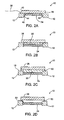
- Figs. 1A-1C depict one embodiment of a
transducer connection apparatus 10 according to the present invention.Transducer connection apparatus 10 includes awasher 12.Washer 12 has an outer diameter 16 and aninner diameter 14 defining awasher hole 15.Washer 12 further includes afirst washer surface 18, asecond washer surface 20 and awasher thickness 22. -
Connection apparatus 10 includes atransducer element 24 having a diameter 34, afirst face 35 and asecond face 37. Transducer element diameter 34 and washerinner diameter 14 are adapted to allowtransducer element 24 to be at least partially disposed withinwasher hole 15.Transducer element 24 may comprise piezocomposite materials, piezoceramics (such as PZT), piezoplastics, and the like. -
Connection apparatus 10 further includes amatching layer 26, having a firstmatching layer surface 28, a secondmatching layer surface 30, amatching layer thickness 32 and amatching layer diameter 36.Matching layer 26 is operably attached towasher 12, and preferably, is operably attached tofirst washer surface 18. - Preferably, washer outer diameter 16 is greater than matching
layer diameter 36, and matchinglayer diameter 36 is greater than transducer element diameter 34.Transducer element 24 is disposed withinwasher hole 15 so that matchinglayer 26 is operably attached towasher 12 and totransducer element 24, and more preferably to transducerfirst face 35. Alternatively, matchinglayer 26 andtransducer element 24 are proximate each other to provide for an electrical connection therebetween. In somecases transducer element 24 may be partially disposed withinwasher hole 15, such as whentransducer element 24 has a thickness that is greater thanwasher thickness 22. - While Figs. 1A-1C depict
washer 12,transducer element 24 andmatching layer 26 as generally disk-shaped, these components may have a variety of shapes within the present invention. For example,washer 12,transducer element 24 andmatching layer 26 may be generally elliptical or oval in shape. In such a configuration,diameters 34 and 36 would bemajor axis 34 and 36, outer diameter 16 would be an outer major axis 16 andinner diameter 14 would be an innermajor axis 14. - The physical arrangement of
washer 12,transducer element 24 andmatching layer 26 permit an electrical connection to be established betweentransducer element 24 andwasher 12. Such a connection may be accomplished using a variety of methods. For example,washer 12 andmatching layer 26 may at least partially comprise electrically conductive materials. In this manner, electrical signals may be transferred betweenwasher 12 andmatching layer 26, and betweenmatching layer 26 andtransducer element 24. - More preferably, as shown in Fig. 1C, second
matching layer surface 30 is operably attached to bothtransducer element 24 and washerfirst surface 18 using a thin layer of electrically conductive or non-conductive adhesive (not shown). The adhesive layer is thin enough to be generally acoustically transparent. - The use of an electrically conductive adhesive layer establishes an electrical connection between
transducer element 24 andfirst washer surface 18. The adhesive layer provides the electrical conductive path betweentransducer element 24 and washerfirst surface 18. Further, the use of electrically conductive adhesive permits the use of matchinglayer 26 comprising either electrically conductive materials, such as silver-filled epoxy, tungsten-filled epoxy, or the like, or electrically non-conductive materials, such as mylar, polyimide, polyurethane or the like. - Alternatively, matching
layer 26 can be operably attached totransducer element 24 andfirst washer surface 18 using a thin layer of electrically non-conductive adhesive. In such an embodiment, matchinglayer 26 comprises an electrically conductive material, or secondmatching layer face 30 is coated with an electrically conductive material. The non-conductive adhesive layer is thin enough to permit a molecular contact between transducerfirst face 35 and secondmatching layer surface 30. The result is an ohmic, electrically-conductive contact. In addition, some roughness to the secondmatching layer surface 30, or to transducerfirst face 35 facilitates an electrically conductive bond. Similarly, secondmatching layer surface 30 is electrically coupled tofirst washer face 18. -
Washer 12 may comprise electrically conductive materials, such as brass, copper, stainless steel or the like.Washer 12 also may comprise electrically non-conductive materials, such as polyimide, vinyl, mylar or the like. Forwasher 12 comprising electrically conductive material, a lead 38 may be attached using anattachment point 40 made directly towasher 12.Lead 38 then may be connected to other electronics, such as to ultrasound imaging equipment and the like. Forwasher 12 comprising electrically non-conductive material,washer 12 may require an electrode, electrically conductive film, or the like to be attached towasher 12 in order to complete an electrical connection totransducer element 24. -
Washer 12 also may comprise a flexible circuit board. A flex circuit typically consists of a substrate, for example a polyimide substrate, and an electrode pattern, preferably comprising a gold-plated or a copper electrode pattern. The flex circuit electrodes are electrically connected to lead 38 and to either an electrically conductive adhesive or to matchinglayer 26 to permitwasher 12 to be in electrical communication withtransducer element 24. - Once
washer 12 andtransducer element 24 are in electrical communication, electrical signals may be sent to and received fromtransducer element 24 by connecting electronics, such as ultrasound imaging equipment, towasher 12. - As best shown in Fig. 1C, transducer element diameter 34 is about equal to washer
inner diameter 14, so thattransducer element 24 is in contact with aninner edge 42 ofwasher 12.Transducer element 24 may be operably attached towasher 12 using electrically conductive epoxy, electrically non-conductive epoxy, or the like. Such material also may serve as a transducer backing material, depending upon the method used to establish a back side electrical connection, negative contact or ground for the transducer, as further described below. Physical contact betweentransducer element 24 and washerinner edge 42 results intransducer element 24 andwasher 12 being acoustically coupled. Such a relationship does not significantly degradetransducer element 24 operation, provided thatwasher 12 comprises material that is acoustically lossive, such as epoxy, rubber or the like. - In order to send electrical signals to, or receive signals from,
transducer element 24, an electrical connection only need be made towasher 12.Apparatus 10 thereby eliminates the need to solder or otherwise affix an electrical connection, such aslead 38, directly totransducer element 24 or to matchinglayer 26. Leadattachment point 40, which may include silver, gold/chrome, gold/chrome/nickel, copper or the like, is made towasher 12. By makingattachment point 40 towasher 12, instead of to transducer elementfirst face 35 or to firstmatching layer surface 28,attachment point 40 does not interfere with ultrasound signals sent and/or received bytransducer element 24. As a result, the variability ofattachment point 40 size and location is a reduced concern due to its minimal impact ontransducer element 24 performance. - Turning now to Figs. 2A-2D, alternative connection apparatus according to the present invention will be described. Fig. 2A depicts
connection apparatus 10 as previously described in conjunction with Figs. 1A-1C, with the exception that transducer element diameter 34 is smaller than washerinner diameter 14. This results in agap 44, preferably an air-filled gap, betweentransducer element 24 and washerinner edge 42. In such an embodiment,transducer element 24 is operably attached to matchinglayer 26, or to other components of an imaging assembly (not shown in Fig. 2). The back side electrical connection totransducer element 24 is made using electrically conductive transducer backing (see Fig. 3A). -
Transducer connection apparatus 10 depicted in Figs. 2B and 2C are similar toapparatus 10 described in conjunction with Fig. 1, with the exception that the adhesive film is enlarged to comprise abond layer 50.Bond layer 50 preferably comprises an electrically conductive, adhesive material to operably attach matchinglayer 26 towasher 12 andtransducer element 24. For example,bond layer 50 may comprise silver epoxy or the like.Bond layer 50 further preferably has an ultrasound impedance that is between the impedance oftransducer element 24 and the impedance of matchinglayer 26. Such relative impedances facilities an in-phase alignment of the ultrasonic signal propagated bytransducer element 24 with the portion of the propagated signal reflected bybond layer 50. Multiple matching layers result in improved efficiency and band width compared to single matching layer designs due, in part, to providing smaller, but more frequent impedance changes between the transducer and the surrounding tissue or fluid being imaged. - Fig. 2B depicts
bond layer 50 fully disposed withinwasher hole 15. In such a configuration, matchinglayer 26 preferably is electrically conductive to provide an electrical connection betweenmatching layer 26 andwasher 12. As a result, an electrical connection betweentransducer element 24 andwasher 12 is established. Alternatively, secondmatching layer surface 30 can comprise electrically conductive material, or be coated with electrically conductive material to facilitate an electrical connection betweenbond layer 50 andwasher 12. - Fig. 2C depicts
bond layer 50 being partially disposed withinwasher hole 15. Such an arrangement is particularly useful when matchinglayer 26 comprises an electrically non-conductive material. Electricallyconductive bond layer 50 provides the electrical connection betweentransducer element 24 andfirst washer surface 18. - Fig. 2D depicts
transducer connection apparatus 10 havingbond layer 50 comprising an electrically non-conductive material. Bond layer 50 (not cross-hatched for convenience of illustration) contains an electrode or lead 52, which operably connectstransducer element 24 towasher 12. In this manner, lead 52 transmits electrical signals fromtransducer element 24 towasher 12. Alternatively,bond layer 50 may comprise electrically non-conductive material and be fully disposed within washer hole 15 (as depicted in Fig. 2B). In such an embodiment, matchinglayer 26 preferably comprises electrically conductive material and lead 52 provides an electrical connection betweentransducer element 24 and secondmatching layer surface 30. Secondmatching layer surface 30 is in electrical communication withwasher 12. As will be appreciated by those skilled in the art, modifications may be made to the above described embodiments within the scope of the present invention. For example, additional matching layers may be added, provided the desired electrical connection betweentransducer element 24 andwasher 12 is maintained. - Turning now to Figs. 3A and 3B, exemplary imaging assemblies according to the present invention will be described. An
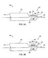
imaging assembly 100 comprises ahousing 110, having adistal end 112, aproximal end 114 and alongitudinal axis 116. Whilehousing 110 is shown to have a generally cylindrical shape,other housing 110 shapes are possible within the scope of the present invention.Housing 110 preferably comprises a hollow housing for embodiments having a throughhole with solid transducer backing, although a solid housing can be used within the scope of the present invention.Housing 110 preferably comprises stainless steel, nickel-plated steel, tin-plated steel, gold-plated steel or the like. Such materials provide sufficient mechanical strength to enablehousing 110 to be operably attached to a cable, such as a stainless steel drive cable (not shown in Fig. 3).Housing 110 also can comprise an epoxy-like material, plastics or the like. Such materials provide desirable sound attenuating and/or electrical conductivity properties. -
Imaging assembly 100 further includes atransducer connection apparatus 120. As previously described in conjunction with Figs. 1 and 2,connection apparatus 120 includes awasher 122, atransducer element 124, amatching layer 126 and a lead 128 operably attached towasher 122. Fig. 3A depicts an embodiment without a bond layer. Fig. 3B depicts an embodiment having abond layer 118 as previously described.Bond layer 118 is betweenmatching layer 126 andtransducer element 124, and is operably attached towasher 122 surface.Housing 110 further includes a throughhole 130 formed through at least a portion ofhousing 110, and a generallyflat surface 132 located neardistal end 112.Connection apparatus 120 is operably attached to surface 132 in a manner which positionstransducer element 124 over an opening to throughhole 130.Washer 122 further operably attaches to surface 132 in a manner which positionstransducer element 124 at a known offset fromlongitudinal axis 116. Offset is defined as the distance thetransducer element 124 upper surface is located away fromaxis 116. Furthermore,transducer element 124 is positioned at a known angular relationship toaxis 116 by operably attachingwasher 122 tosurface 132. Fig. 3 depictssurface 132,transducer 124 andaxis 116 as being generally parallel. - For
housing 110 comprising stainless steel, or the like, it is preferable to havetransducer element 124 fully disposed within the washer hole (as shown in Fig. 3), because lateral coupling to hard materials such as steel is acoustically undesirable. Forhousing 110 comprising epoxy, plastics or the like,transducer element 124 can extend intothroughhole 130 without degradingtransducer element 124 performance. -
Throughhole 130 preferably is filled with abacking material 136.Backing material 136 is selected to have sound attenuating qualities so that ultrasound signals propagated into the backing are not reflected by backingmaterial 136, which would result in artifacts.Backing material 136 may comprise electrically conductive material, such as epoxy, silver/tungsten epoxy or the like. In such an embodiment,transducer element 124 preferably rests on, and/or is operably attached to,backing material 136. In this manner, electricallyconductive backing material 136 provides a back side electrical connection or negative conductive path, or ground, betweentransducer element 124 andhousing 110. - Alternatively, backing
material 136 may comprise electrically non-conductive material, such as epoxy, polyurethane, rubber or the like. In such an embodiment having non-conductive backing,transducer element 124 preferably has a second lead (not shown) to connect the throughhole-facing surface oftransducer element 124 tohousing 110. Other methods of creating an electrical connection betweentransducer element 124 andhousing 110 are possible. For example, electrically conductive epoxy, or the like can be used to directly connect the throughhole-facing surface oftransducer element 124 tohousing 110.Transducer element 124 also may be grounded by connectingtransducer element 124 directly to an electricallyconductive washer 122 that is, in turn, connected tohousing 110. Such a connection may be made using electrically conductive epoxy or the like.Washer 122 can provide both the positive and negative connection provided that the two are kept separate. For instance, a center conductor and shield of a miniature coaxial cable can be terminated to the washer, which provides both the positive and negative connection totransducer element 124. -
Imaging assembly 100 therefore provides a way to move the electrical attachment point forlead 128 towasher 122.Imaging assembly 100 furtherpositions transducer element 124 at a known offset and angular relationship toaxis 116 by mountingconnection apparatus 120 tosurface 132. In contrast, manually positioned and attached transducer elements are typically attached withinthroughhole 130. Such transducer elements have an offset and angular relationship that can vary between otherwise identical imaging assemblies. Lead 128 preferably is adapted to be in communication with a cable, and more preferably, with an integrated coaxial/drive cable. In this manner, electrical signals can be sent to, and received from,transducer element 124. - Turning now to Figs. 4A and 4B, alternative imaging assemblies according to the present invention will be described. An
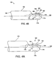
imaging assembly 150 includes ahousing 152, having adistal end 154, aproximal end 156 and alongitudinal axis 158. Atransducer connection apparatus 160 is provided, having awasher 162, atransducer element 164 and amatching layer 166. Fig. 4B depictsapparatus 150 also having abond layer 168 disposed withinwasher 162 hole.Connection apparatus 160 is similar toconnection apparatus 10 described in conjunction with Figs. 1 and 2. -
Imaging assembly 150 includes alead 170, and an air-filledcavity 172 inhousing 152.Cavity 172 may comprise a throughhole as shown in Fig. 2 with acap 176 enclosing a second end of the throughhole. Alternatively,cavity 172 may comprise a cavity that does not extend completely throughhousing 152. Since air has an acoustic impedance of about 0.0004 megarayls, air-filledcavity 172 provides a nearly perfect reflection. Therefore, ultrasound waves typically will not emanate from the cavity-facing side oftransducer element 164.Imaging assembly 150 may have one or more matching layers 166. As shown in Fig. 4B,imaging assembly 150 hasbond layer 168 acting as the second matching layer fortransducer element 164. Sincetransducer element 164 cannot be operably attached to a backing material inassembly 150,transducer element 164 preferably is operably attached to the interior walls ofcavity 172 using at least oneattachment point 174. Attachment points 174 may comprise electrically conductive epoxy, or the like. Alternatively, a back side electrical connection or ground connection may be established by operably attachingtransducer element 164 towasher 162, providedwasher 162 is electrically conductive and is operably attached tohousing 152. - Turning now to Figs. 5A and 5B, a
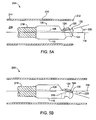
catheter system 200 according to the present invention will be described.Catheter system 200 comprises a catheter body orsheath 210 having adistal end 212, aproximal end 214, and a workinglumen 216.Sheath 210 preferably is fully sonolucent, or includes a portion of sonolucent material, to provide desirable acoustic transmissiveness.Sheath 210 may comprise nylon, polyethylene or the like.Imaging assembly 100 is disposed withinlumen 216 and operably attached to acable 218.Cable 218 preferably comprises an integrated coaxial/drive cable.Exemplary cables 218 are described in U.S. Patent Application Serial No. 09/017,578, entitled "Integrated Coaxial Transmission Line and Flexible Drive Cable", the complete disclosure of which is hereby incorporated by reference.Imaging assembly 100 preferably is operably attached to a distal end ofcable 218 by welding, electrically conductive adhesive or the like. This results in a mechanical connection betweenimaging assembly 100 andcable 218. Rotation ofcable 218, in turn, rotatesimaging assembly 100. -
Imaging assembly 100, and in particular,connection apparatus 120, are essentially as described in conjunction with Fig. 3. As shown in Fig. 5A and 5B,housing 110 is formed withsurface 132 having a desiredangle 222 with respect toaxis 116.Angle 222 preferably is between about +60 degrees and about -60 degrees, and more preferably, between about + 15 degrees (as approximately shown in Fig. 5A) and about - 15 degrees (as approximately shown in Fig. 5B). By creatingangle 222, ultrasound signals transmitted bytransducer element 124 are less likely to be reflected by sheath orcatheter body 210 during operation ofcatheter system 200. - By forming
housing 100 so thatsurface 132 is at knownangle 222 with respect toaxis 116,transducer element 124 likewise is positioned at a known angle with respect toaxis 116. In contrast, attachingtransducer element 124 by hand to the inside ofcavity 130, as may be done in the prior art, results in variations in the angle betweenaxis 116 andtransducer element 124. Therefore,catheter system 200 reduces or eliminates the catheter-to-catheter variation inangle 222 that typically occurs whentransducer element 124 is attached by hand. - As shown in Figs. 5A and 5B, lead 128 preferably is operably attached to
washer 122 and tocable 218. In this manner, an electrical connection is established betweentransducer element 124 andcable 218.Cable 218, preferably an integrated coaxial/drive cable, then can be used to transmit signals fromtransducer element 124 to desired electronics, such as ultrasound imaging electronics maintained outside a patient's body. Similarly, the desired electronics can transmit a signal throughcable 218, throughlead 128, and towasher 122. As previously discussed, a positive electrical connection is made betweenwasher 122 andtransducer element 124 to allow the signal to reachtransducer element 124. Lead 128 may comprise a center wire or lead from integrated coaxial/drive cable 218. In such an embodiment, the coaxial cable shield (not shown in Fig. 5) is terminated at a distal end ofdrive cable 218. The coaxial center wire or lead comprises, or operably attaches to, lead 128.Lead 128 is operably attached towasher 122, as previously discussed. A back side electrical connection or negative connection or ground is established betweentransducer element 124 andhousing 110 as previously discussed. For example, asecond electrode 220 may be used to connect a cavity-facing side oftransducer element 124 tohousing 110 or to the coaxial cable shield (not shown). - The operation of
catheter system 200 comprises insertingcatheter system 200 into a patient andpositioning imaging assembly 100 at a desired location within the patient's anatomy.Drive cable 218 is rotated which, in turn, rotatesimaging assembly 100 containingtransducer element 124.Transducer element 124 is excited using an electrical or other signal transmitted throughcable 218 and intotransducer element 124.Transducer element 124 propagates ultrasound signals into the patient's tissue surrounding theimaging assembly 100. Ultrasound signals reflect off the patient's tissue and are received bytransducer element 124. The present invention, using improved transducer connection apparatus, reduces or eliminates the signal interference typically caused by attaching a lead or electrode to thetransducer element 124 surface. The reflected signals are transmitted throughcable 218 to ultrasound signal processing electronics which produces an image of the patient's tissue. - The invention has now been described in detail. However, it will be appreciated that certain changes and modifications may be made. Therefore, the scope and content of this invention are not limited by the foregoing description. Rather, the scope and content are to be defined by the following claims.
Claims (47)
- A transducer apparatus (10), comprising:a washer (12) having a hole (15) extending therethrough and a washer surface (18);a transducer element (24) at least partially disposed within said washer hole (15); anda matching layer (26) having first and second matching layer surfaces (28,30) defining a thickness therebetween, said second matching layer surface (30) being operably attached to both said washer surface (18) and to said transducer element (24);characterised by a lead (38) operably attached to said washer (12), and in that an electrical connection is provided between the lead (38) and said transducer element (24) via said washer (12).
- A transducer apparatus (10) as in claim 1, wherein said matching layer (26) comprises a material having an acoustic impedance that is lower than an acoustic impedance of said transducer element.
- A transducer apparatus (10) as in claim 1, wherein at least a portion of said matching layer (26) comprises an electrically conductive material.
- A transducer apparatus (10) as in claim 1, wherein said second matching layer surface (30) comprises electrically conductive material.
- A transducer apparatus (10) as in claim 1, wherein said second matching layer surface (30) is operably attached to said washer (12) using an electrically conductive adhesive material.
- A transducer apparatus (10) as in claim 4, wherein said second matching layer surface (30) is operably attached to said washer (12) using an electrically non-conductive adhesive material.
- A transducer apparatus (10) as in claim 4, wherein said second matching layer surface (30) is operably attached to said washer (12) using an electrically conductive adhesive material.
- A transducer apparatus (10) as in claim 1, wherein said washer (12) comprises a flexible circuit.
- A transducer apparatus (10) as in claim 1, wherein said washer (12) comprises a polyimide having at least one electrode.
- A transducer apparatus (10) as in claim 1, wherein at least a portion of said washer (12) comprises an electrically conductive material.
- A transducer apparatus (10) as in claim 1, wherein said washer (12) has first and second washer surfaces (18,20), an outer diameter (16) and an inner diameter (14), said washer outer diameter (16) being greater than a matching layer diameter.
- A transducer apparatus (10) as in claim 1, wherein said washer (12) has first and second washer surfaces (18,20), an outer major axis and an inner major axis, said washer outer major axis being greater than a matching layer major axis.
- A transducer apparatus (10) as in claim 12, wherein said first washer surface (18) comprises an electrically conductive material and is operably attached to said matching layers (26).
- A transducer apparatus (10) as in claim 13, further comprising a lead (38) that is operably attached to said first washer surface (18).
- A transducer apparatus (10) as in claim 1, wherein said transducer element (24) is disposed within said washer hole (15) so that said transducer element is in communication with an inner edge (42) of said washer (12).
- A transducer apparatus (10) as in claim 1, wherein said transducer element (24) is disposed within said washer hole (15) so that a gap (44) is formed between said transducer element (24) and an inner edge (42) of said washer (12).
- A transducer apparatus (10) as in claim 1, wherein said transducer element (24), said washer (12) and said matching layer (26) are all generally disk-shaped.
- A transducer apparatus (10) as in claim 1, wherein said matching layer (26) and said transducer element (24) each have a diameter, and wherein said matching layer diameter is greater than said transducer element diameter.
- A transducer apparatus (10) as in claim 1, wherein said matching layer (26) and said transducer element (24) each have a major axis, and wherein said matching layer major axis is greater than said transducer element major axis.
- A transducer apparatus (10) as in claim 1, wherein said washer (12) and said transducer element (24) each have a thickness, and wherein said washer thickness is greater than said transducer element thickness so that said transducer element (24) is fully disposed within said washer hole (15).
- A transducer apparatus (10) according to claim 1, further comprising a bond layer (50) for attaching the transducer element (24) to the matching layer (26) to establish the electrical connection between said washer (12) and said transducer element (24).
- A transducer apparatus (10) as in claim 21, further comprising said bond layer (50) being at least partially disposed within said washer hole (15).
- A transducer apparatus (10) as in claim 21, wherein said bond layer (50) comprises an adhesive, electrically conductive material for bonding said transducer element (24) and said washer (12) to said matching layer (26).
- A transducer apparatus (10) as in claim 21, wherein said bond layer (50) comprises an adhesive, electrically non-conductive material for bonding said transducer element (24) and said washer (12) to said matching layer (26), said bond layer (50) further comprising an electrode (52) within said bond layer, said electrode (50) being operably attached to said transducer element (24) and said washer (12).
- A transducer apparatus (10) as in claim 21, wherein said bond layer (50) comprises a material having an acoustic impedance that is lower than an acoustic impedance of said transducer element (24) and higher than an acoustical impedance of said matching layer (26).
- An imaging assembly (100), comprising:a housing (110) having a distal end (112), a proximal end (114) and a longitudinal axis (116); anda transducer apparatus (120) operably attached to said housing, said transducer apparatus (120) being in accordance with claim 1.
- An imaging assembly (100) as in claim 26, further comprising a lead (128) operably attached to said washer (122).
- An imaging assembly (100) as in claim 27, wherein said housing (110) and said lead (128) are adapted to be attached to a cable.
- An imaging assembly (100) as in claim 27, wherein said housing (110) and said lead (128) are adapted to be attached to an integrated coaxial/drive cable.
- An imaging assembly (100) as in claim 26, wherein a portion of said housing (110) forms a generally flat surface (132) to which said transducer apparatus (120) is operably attached.
- An imaging assembly (100) as in claim 30, wherein said surface (132) is positioned generally parallel to said housing longitudinal axis (116).
- An imaging assembly (100) as in claim 30, wherein said surface (132) is positioned to form a desired angle with said housing longitudinal axis (116).
- An imaging assembly (100) as in claim 32, wherein said desired angle is between about -60 degrees and about +60 degrees.
- An imaging assembly (100) as in claim 30, wherein said housing (110) is formed with a throughhole (130), and wherein said washer (12) is operably attached to said surface (132) to at least partially cover a first opening of said throughhole (130).
- An imaging assembly (100) as in claim 34, further comprising a backing material (136) within said throughhole (130).
- An imaging assembly (100) as in claim 35, wherein said backing material (136) comprises a sound-attenuating material.
- An imaging assembly (100) as in claim 35, wherein said backing material (136) comprises an electrically conductive material and wherein said transducer element (124) is in electrical communication with said backing material (136).
- An imaging assembly (100) as in claim 3 5, wherein said backing material (136) comprises an electrically non-conductive material, and further comprising an electrode (220) operably attached to said transducer element (124) and said housing (110).
- An imaging assembly (100) as in claim 34, wherein said housing (110) further comprises a cap (176) to enclose a second opening of said throughhole (130) to create an air-filled cavity.
- An imaging assembly (100) as in claim 26, wherein said transducer element (124) is in electrical communication with said housing (110).
- An imaging assembly (100) as in claim 26, wherein said transducer element (124) is fully disposed within said washer hole.
- An imaging assembly (100) as in claim 26, further comprising an electrode (220) operably attached to said transducer element (124) and said washer (122) to provide a second electrical connection between said transducer element and said washer.
- An imaging assembly (100) according to claim 26, in which said housing (110) is formed with an air-filled cavity, and in which the transducer apparatus (120) at least partially covers an opening of said cavity when operably attached to said housing (110).
- An imaging assembly (100) as in claim 43, wherein said transducer element (124) is in electrical communication with said housing (110).
- An imaging assembly (100) as in claim 43, further comprising a second matching layer operably attached between said transducer element (124) and said first matching layer (126).
- A catheter system (200), comprising:a catheter body (210) having a distal end (212), a proximal end (214) and a working lumen (216);a cable (218) disposed within said working lumen (12G); andan imaging assembly (100) operably attached to a distal end of said cable (218), said imaging assembly comprisinga housing (110) anda transducer apparatus (120) operably attached to said housing (110), said transducer apparatus (120) being in accordance with any one of claims 1 to 26;wherein said transducer element (124) is in electrical communication with both said housing (110) and said cable (218).
- A catheter system (200) as in claim 47, wherein said cable (218) comprises an integrated coaxial/drive cable.
Applications Claiming Priority (3)
| Application Number | Priority Date | Filing Date | Title |
|---|---|---|---|
| US127089 | 1998-07-31 | ||
| US09/127,089 US6113546A (en) | 1998-07-31 | 1998-07-31 | Off-aperture electrical connection for ultrasonic transducer |
| PCT/IB1999/001348 WO2000006309A2 (en) | 1998-07-31 | 1999-07-29 | Off-aperture electrical connection for ultrasonic transducer |
Publications (2)
| Publication Number | Publication Date |
|---|---|
| EP1100628A2 EP1100628A2 (en) | 2001-05-23 |
| EP1100628B1 true EP1100628B1 (en) | 2006-06-07 |
Family
ID=22428248
Family Applications (1)
| Application Number | Title | Priority Date | Filing Date |
|---|---|---|---|
| EP99933066A Expired - Lifetime EP1100628B1 (en) | 1998-07-31 | 1999-07-29 | Off-aperture electrical connection for ultrasonic transducer |
Country Status (7)
| Country | Link |
|---|---|
| US (2) | US6113546A (en) |
| EP (1) | EP1100628B1 (en) |
| JP (1) | JP2002521163A (en) |
| CA (1) | CA2339130A1 (en) |
| DE (1) | DE69931788T2 (en) |
| ES (1) | ES2265185T3 (en) |
| WO (1) | WO2000006309A2 (en) |
Families Citing this family (23)
| Publication number | Priority date | Publication date | Assignee | Title |
|---|---|---|---|---|
| US6723063B1 (en) | 1998-06-29 | 2004-04-20 | Ekos Corporation | Sheath for use with an ultrasound element |
| AU2002359576A1 (en) | 2001-12-03 | 2003-06-17 | Ekos Corporation | Catheter with multiple ultrasound radiating members |
| JP4167178B2 (en) * | 2001-12-14 | 2008-10-15 | イコス コーポレイション | Determination of resumption of blood flow |
| US6958040B2 (en) | 2001-12-28 | 2005-10-25 | Ekos Corporation | Multi-resonant ultrasonic catheter |
| US8226629B1 (en) | 2002-04-01 | 2012-07-24 | Ekos Corporation | Ultrasonic catheter power control |
| EP1575429A1 (en) * | 2002-12-11 | 2005-09-21 | Koninklijke Philips Electronics N.V. | Miniaturized ultrasonic transducer |
| AU2003900260A0 (en) * | 2003-01-22 | 2003-02-06 | Uscom Pty Ltd | Ultrasonic transducer device |
| US20050154308A1 (en) | 2003-12-30 | 2005-07-14 | Liposonix, Inc. | Disposable transducer seal |
| US9107590B2 (en) | 2004-01-29 | 2015-08-18 | Ekos Corporation | Method and apparatus for detecting vascular conditions with a catheter |
| US7698949B2 (en) * | 2005-09-09 | 2010-04-20 | The Boeing Company | Active washers for monitoring bolted joints |
| US8192363B2 (en) | 2006-10-27 | 2012-06-05 | Ekos Corporation | Catheter with multiple ultrasound radiating members |
| US10182833B2 (en) | 2007-01-08 | 2019-01-22 | Ekos Corporation | Power parameters for ultrasonic catheter |
| US9044568B2 (en) | 2007-06-22 | 2015-06-02 | Ekos Corporation | Method and apparatus for treatment of intracranial hemorrhages |
| US7559302B2 (en) * | 2007-11-15 | 2009-07-14 | Harley-Davidson Motor Company Group, LLC | Thermally insulating element for an engine valve assembly |
| US8386118B2 (en) | 2009-08-04 | 2013-02-26 | The Boeing Company | System and method for detecting an anomaly in a hidden layer of a multi-layer structure |
| US9707413B2 (en) * | 2010-03-09 | 2017-07-18 | Profound Medical Inc. | Controllable rotating ultrasound therapy applicator |
| US11027154B2 (en) * | 2010-03-09 | 2021-06-08 | Profound Medical Inc. | Ultrasonic therapy applicator and method of determining position of ultrasonic transducers |
| US11458290B2 (en) | 2011-05-11 | 2022-10-04 | Ekos Corporation | Ultrasound system |
| US9530955B2 (en) * | 2011-11-18 | 2016-12-27 | Acist Medical Systems, Inc. | Ultrasound transducer and processing methods thereof |
| US20130303907A1 (en) * | 2012-05-11 | 2013-11-14 | Volcano Corporation | Device and System For Imaging and Blood Flow Velocity Measurement |
| US10092742B2 (en) | 2014-09-22 | 2018-10-09 | Ekos Corporation | Catheter system |
| EP3307388B1 (en) | 2015-06-10 | 2022-06-22 | Ekos Corporation | Ultrasound catheter |
| CN109596183B (en) * | 2018-12-26 | 2024-04-05 | 无锡市宇超电子有限公司 | Flow transducer |
Citations (1)
| Publication number | Priority date | Publication date | Assignee | Title |
|---|---|---|---|---|
| DE4235089C1 (en) * | 1992-10-17 | 1994-03-31 | Pil Sensoren Gmbh | Ultrasound transducer with piezoelectric element - has weighting ring with radial incisions concentric to transducer element on matching body |
Family Cites Families (27)
| Publication number | Priority date | Publication date | Assignee | Title |
|---|---|---|---|---|
| DE2541492C3 (en) * | 1975-09-17 | 1980-10-09 | Siemens Ag, 1000 Berlin Und 8000 Muenchen | Ultrasonic transducer |
| JPS5353393A (en) * | 1976-10-25 | 1978-05-15 | Matsushita Electric Ind Co Ltd | Ultrasonic probe |
| US4217684A (en) * | 1979-04-16 | 1980-08-19 | General Electric Company | Fabrication of front surface matched ultrasonic transducer array |
| US4348283A (en) * | 1980-11-05 | 1982-09-07 | Purdue Research Foundation | Reciprocating dialyzer having spacers |
| JPS59119999A (en) * | 1982-12-27 | 1984-07-11 | Toshiba Corp | Ultrasonic wave transducer |
| AU544464B2 (en) * | 1982-12-27 | 1985-05-30 | Tokyo Shibaura Denki Kabushiki Kaisha | Ultrasonic transducer |
| JPS59141060A (en) * | 1983-01-31 | 1984-08-13 | Fujitsu Ltd | Ultrasonic probe |
| JPS61161446A (en) | 1985-01-10 | 1986-07-22 | Terumo Corp | Ultrasonic wave probe and its production |
| DE3501808A1 (en) | 1985-01-21 | 1986-07-24 | Siemens AG, 1000 Berlin und 8000 München | ULTRASONIC CONVERTER |
| US4889128A (en) * | 1985-09-13 | 1989-12-26 | Pfizer Hospital Products | Doppler catheter |
| US4794931A (en) * | 1986-02-28 | 1989-01-03 | Cardiovascular Imaging Systems, Inc. | Catheter apparatus, system and method for intravascular two-dimensional ultrasonography |
| US4861332A (en) * | 1986-04-14 | 1989-08-29 | Ultramed Corporation | Ultrasonic probe |
| US5108369A (en) * | 1990-03-15 | 1992-04-28 | Diagnostic Devices Group, Limited | Dual-diameter multifunction catheter |
| JPH04127800A (en) * | 1990-09-19 | 1992-04-28 | Toshiba Ceramics Co Ltd | Piezoelectric transducer |
| DE4233256C1 (en) * | 1992-10-02 | 1993-12-02 | Endress Hauser Gmbh Co | Acoustic or ultrasonic transducers |
| US5423220A (en) | 1993-01-29 | 1995-06-13 | Parallel Design | Ultrasonic transducer array and manufacturing method thereof |
| US5359760A (en) | 1993-04-16 | 1994-11-01 | The Curators Of The University Of Missouri On Behalf Of The University Of Missouri-Rolla | Method of manufacture of multiple-element piezoelectric transducer |
| DE4427798C2 (en) | 1993-08-06 | 1998-04-09 | Toshiba Kawasaki Kk | Piezoelectric single crystal and its use in an ultrasonic probe and ultrasonic array probe |
| JP3327497B2 (en) * | 1994-05-26 | 2002-09-24 | 日本電波工業株式会社 | Ultrasonic probe |
| JPH0833097A (en) * | 1994-07-13 | 1996-02-02 | Olympus Optical Co Ltd | Piezoelectric element |
| US5511550A (en) | 1994-10-14 | 1996-04-30 | Parallel Design, Inc. | Ultrasonic transducer array with apodized elevation focus |
| JPH08307995A (en) * | 1995-05-08 | 1996-11-22 | Ge Yokogawa Medical Syst Ltd | Ultrasonic probe |
| JPH0965489A (en) * | 1995-08-24 | 1997-03-07 | Olympus Optical Co Ltd | Ultrasonic probe |
| EP0766070B1 (en) | 1995-09-28 | 2001-07-04 | Endress + Hauser Gmbh + Co. | Ultrasonic transducer |
| US5732706A (en) * | 1996-03-22 | 1998-03-31 | Lockheed Martin Ir Imaging Systems, Inc. | Ultrasonic array with attenuating electrical interconnects |
| US5857974A (en) * | 1997-01-08 | 1999-01-12 | Endosonics Corporation | High resolution intravascular ultrasound transducer assembly having a flexible substrate |
| US5920972A (en) | 1997-06-27 | 1999-07-13 | Siemens Medical Systems, Inc. | Interconnection method for a multilayer transducer array |
-
1998
- 1998-07-31 US US09/127,089 patent/US6113546A/en not_active Expired - Fee Related
-
1999
- 1999-07-29 EP EP99933066A patent/EP1100628B1/en not_active Expired - Lifetime
- 1999-07-29 DE DE69931788T patent/DE69931788T2/en not_active Expired - Fee Related
- 1999-07-29 ES ES99933066T patent/ES2265185T3/en not_active Expired - Lifetime
- 1999-07-29 WO PCT/IB1999/001348 patent/WO2000006309A2/en active IP Right Grant
- 1999-07-29 CA CA002339130A patent/CA2339130A1/en not_active Abandoned
- 1999-07-29 JP JP2000562150A patent/JP2002521163A/en active Pending
-
2000
- 2000-07-10 US US09/613,819 patent/US6733456B1/en not_active Expired - Fee Related
Patent Citations (1)
| Publication number | Priority date | Publication date | Assignee | Title |
|---|---|---|---|---|
| DE4235089C1 (en) * | 1992-10-17 | 1994-03-31 | Pil Sensoren Gmbh | Ultrasound transducer with piezoelectric element - has weighting ring with radial incisions concentric to transducer element on matching body |
Also Published As
| Publication number | Publication date |
|---|---|
| DE69931788T2 (en) | 2007-06-14 |
| WO2000006309A2 (en) | 2000-02-10 |
| WO2000006309A3 (en) | 2000-05-04 |
| ES2265185T3 (en) | 2007-02-01 |
| JP2002521163A (en) | 2002-07-16 |
| US6113546A (en) | 2000-09-05 |
| CA2339130A1 (en) | 2000-02-10 |
| EP1100628A2 (en) | 2001-05-23 |
| US6733456B1 (en) | 2004-05-11 |
| DE69931788D1 (en) | 2006-07-20 |
Similar Documents
| Publication | Publication Date | Title |
|---|---|---|
| EP1100628B1 (en) | Off-aperture electrical connection for ultrasonic transducer | |
| US8353839B2 (en) | Intracavity probe with continuous shielding of acoustic window | |
| EP0637937B1 (en) | Ultrasound catheter probe | |
| EP0646349B1 (en) | Ultrasound imaging probe | |
| US6283920B1 (en) | Ultrasound transducer assembly | |
| EP2316343B1 (en) | Probe for ultrasonic diagnostic apparatus and method of manufacturing the same | |
| EP1825815A1 (en) | Ultrasonic vibrator, and manufacturing method thereof | |
| JP2006198425A (en) | Intraluminal ultrasonic imaging catheter | |
| KR101031010B1 (en) | Pcb and probe therewith | |
| US6287261B1 (en) | Focused ultrasound transducers and systems | |
| US6406433B1 (en) | Off-aperture electrical connect transducer and methods of making | |
| JP2002528205A (en) | Ultrasonic transducer having an inclined support, and method of manufacturing the same | |
| JP4109013B2 (en) | Ultrasonic transducer and method of manufacturing ultrasonic transducer | |
| JPH0734803B2 (en) | Ultrasonic probe | |
| JP3905494B2 (en) | Ultrasonic transducer | |
| JP2003033353A (en) | Ultrasonic wave probe in coelom | |
| KR101565106B1 (en) | Ultrasound transducer using signal path integrated housing | |
| CN117426790A (en) | Ultrasonic probe and ultrasonic diagnostic apparatus | |
| JP2003169396A (en) | Process for producing piezoelectric transducer and piezoelectric transducer |
Legal Events
| Date | Code | Title | Description |
|---|---|---|---|
| PUAI | Public reference made under article 153(3) epc to a published international application that has entered the european phase |
Free format text: ORIGINAL CODE: 0009012 |
|
| 17P | Request for examination filed |
Effective date: 20010129 |
|
| AK | Designated contracting states |
Kind code of ref document: A2 Designated state(s): AT BE CH CY DE DK ES FI FR GB GR IE IT LI LU MC NL PT SE |
|
| 17Q | First examination report despatched |
Effective date: 20030610 |
|
| GRAP | Despatch of communication of intention to grant a patent |
Free format text: ORIGINAL CODE: EPIDOSNIGR1 |
|
| RBV | Designated contracting states (corrected) |
Designated state(s): DE ES FR GB IT |
|
| GRAS | Grant fee paid |
Free format text: ORIGINAL CODE: EPIDOSNIGR3 |
|
| GRAA | (expected) grant |
Free format text: ORIGINAL CODE: 0009210 |
|
| AK | Designated contracting states |
Kind code of ref document: B1 Designated state(s): DE ES FR GB IT |
|
| REG | Reference to a national code |
Ref country code: GB Ref legal event code: FG4D |
|
| REF | Corresponds to: |
Ref document number: 69931788 Country of ref document: DE Date of ref document: 20060720 Kind code of ref document: P |
|
| ET | Fr: translation filed | ||
| REG | Reference to a national code |
Ref country code: ES Ref legal event code: FG2A Ref document number: 2265185 Country of ref document: ES Kind code of ref document: T3 |
|
| PLBE | No opposition filed within time limit |
Free format text: ORIGINAL CODE: 0009261 |
|
| STAA | Information on the status of an ep patent application or granted ep patent |
Free format text: STATUS: NO OPPOSITION FILED WITHIN TIME LIMIT |
|
| 26N | No opposition filed |
Effective date: 20070308 |
|
| PGFP | Annual fee paid to national office [announced via postgrant information from national office to epo] |
Ref country code: ES Payment date: 20080704 Year of fee payment: 10 Ref country code: DE Payment date: 20080731 Year of fee payment: 10 |
|
| PGFP | Annual fee paid to national office [announced via postgrant information from national office to epo] |
Ref country code: IT Payment date: 20080723 Year of fee payment: 10 Ref country code: FR Payment date: 20080707 Year of fee payment: 10 |
|
| PGFP | Annual fee paid to national office [announced via postgrant information from national office to epo] |
Ref country code: GB Payment date: 20080616 Year of fee payment: 10 |
|
| GBPC | Gb: european patent ceased through non-payment of renewal fee |
Effective date: 20090729 |
|
| REG | Reference to a national code |
Ref country code: FR Ref legal event code: ST Effective date: 20100331 |
|
| PG25 | Lapsed in a contracting state [announced via postgrant information from national office to epo] |
Ref country code: FR Free format text: LAPSE BECAUSE OF NON-PAYMENT OF DUE FEES Effective date: 20090731 |
|
| PG25 | Lapsed in a contracting state [announced via postgrant information from national office to epo] |
Ref country code: GB Free format text: LAPSE BECAUSE OF NON-PAYMENT OF DUE FEES Effective date: 20090729 |
|
| PG25 | Lapsed in a contracting state [announced via postgrant information from national office to epo] |
Ref country code: DE Free format text: LAPSE BECAUSE OF NON-PAYMENT OF DUE FEES Effective date: 20100202 |
|
| REG | Reference to a national code |
Ref country code: ES Ref legal event code: FD2A Effective date: 20090730 |
|
| PG25 | Lapsed in a contracting state [announced via postgrant information from national office to epo] |
Ref country code: ES Free format text: LAPSE BECAUSE OF NON-PAYMENT OF DUE FEES Effective date: 20090730 |
|
| PG25 | Lapsed in a contracting state [announced via postgrant information from national office to epo] |
Ref country code: IT Free format text: LAPSE BECAUSE OF NON-PAYMENT OF DUE FEES Effective date: 20090729 |