EP1103121B1 - A method for allocating network resources - Google Patents
A method for allocating network resources Download PDFInfo
- Publication number
- EP1103121B1 EP1103121B1 EP99945014A EP99945014A EP1103121B1 EP 1103121 B1 EP1103121 B1 EP 1103121B1 EP 99945014 A EP99945014 A EP 99945014A EP 99945014 A EP99945014 A EP 99945014A EP 1103121 B1 EP1103121 B1 EP 1103121B1
- Authority
- EP
- European Patent Office
- Prior art keywords
- gate
- call
- network
- called party
- edge device
- Prior art date
- Legal status (The legal status is an assumption and is not a legal conclusion. Google has not performed a legal analysis and makes no representation as to the accuracy of the status listed.)
- Expired - Lifetime
Links
Images


Classifications
-
- H—ELECTRICITY
- H04—ELECTRIC COMMUNICATION TECHNIQUE
- H04M—TELEPHONIC COMMUNICATION
- H04M7/00—Arrangements for interconnection between switching centres
- H04M7/12—Arrangements for interconnection between switching centres for working between exchanges having different types of switching equipment, e.g. power-driven and step by step or decimal and non-decimal
- H04M7/1205—Arrangements for interconnection between switching centres for working between exchanges having different types of switching equipment, e.g. power-driven and step by step or decimal and non-decimal where the types of switching equipement comprises PSTN/ISDN equipment and switching equipment of networks other than PSTN/ISDN, e.g. Internet Protocol networks
- H04M7/1275—Methods and means to improve the telephone service quality, e.g. reservation, prioritisation or admission control
-
- H—ELECTRICITY
- H04—ELECTRIC COMMUNICATION TECHNIQUE
- H04L—TRANSMISSION OF DIGITAL INFORMATION, e.g. TELEGRAPHIC COMMUNICATION
- H04L47/00—Traffic control in data switching networks
- H04L47/70—Admission control; Resource allocation
-
- H—ELECTRICITY
- H04—ELECTRIC COMMUNICATION TECHNIQUE
- H04L—TRANSMISSION OF DIGITAL INFORMATION, e.g. TELEGRAPHIC COMMUNICATION
- H04L47/00—Traffic control in data switching networks
- H04L47/70—Admission control; Resource allocation
- H04L47/72—Admission control; Resource allocation using reservation actions during connection setup
- H04L47/724—Admission control; Resource allocation using reservation actions during connection setup at intermediate nodes, e.g. resource reservation protocol [RSVP]
-
- H—ELECTRICITY
- H04—ELECTRIC COMMUNICATION TECHNIQUE
- H04L—TRANSMISSION OF DIGITAL INFORMATION, e.g. TELEGRAPHIC COMMUNICATION
- H04L47/00—Traffic control in data switching networks
- H04L47/70—Admission control; Resource allocation
- H04L47/80—Actions related to the user profile or the type of traffic
- H04L47/803—Application aware
-
- H—ELECTRICITY
- H04—ELECTRIC COMMUNICATION TECHNIQUE
- H04L—TRANSMISSION OF DIGITAL INFORMATION, e.g. TELEGRAPHIC COMMUNICATION
- H04L47/00—Traffic control in data switching networks
- H04L47/70—Admission control; Resource allocation
- H04L47/80—Actions related to the user profile or the type of traffic
- H04L47/805—QOS or priority aware
-
- H—ELECTRICITY
- H04—ELECTRIC COMMUNICATION TECHNIQUE
- H04L—TRANSMISSION OF DIGITAL INFORMATION, e.g. TELEGRAPHIC COMMUNICATION
- H04L47/00—Traffic control in data switching networks
- H04L47/70—Admission control; Resource allocation
- H04L47/80—Actions related to the user profile or the type of traffic
- H04L47/806—Broadcast or multicast traffic
-
- H—ELECTRICITY
- H04—ELECTRIC COMMUNICATION TECHNIQUE
- H04L—TRANSMISSION OF DIGITAL INFORMATION, e.g. TELEGRAPHIC COMMUNICATION
- H04L61/00—Network arrangements, protocols or services for addressing or naming
-
- H—ELECTRICITY
- H04—ELECTRIC COMMUNICATION TECHNIQUE
- H04L—TRANSMISSION OF DIGITAL INFORMATION, e.g. TELEGRAPHIC COMMUNICATION
- H04L61/00—Network arrangements, protocols or services for addressing or naming
- H04L61/09—Mapping addresses
- H04L61/25—Mapping addresses of the same type
- H04L61/2503—Translation of Internet protocol [IP] addresses
- H04L61/2514—Translation of Internet protocol [IP] addresses between local and global IP addresses
-
- H—ELECTRICITY
- H04—ELECTRIC COMMUNICATION TECHNIQUE
- H04L—TRANSMISSION OF DIGITAL INFORMATION, e.g. TELEGRAPHIC COMMUNICATION
- H04L61/00—Network arrangements, protocols or services for addressing or naming
- H04L61/09—Mapping addresses
- H04L61/25—Mapping addresses of the same type
- H04L61/2503—Translation of Internet protocol [IP] addresses
- H04L61/2539—Hiding addresses; Keeping addresses anonymous
-
- H—ELECTRICITY
- H04—ELECTRIC COMMUNICATION TECHNIQUE
- H04L—TRANSMISSION OF DIGITAL INFORMATION, e.g. TELEGRAPHIC COMMUNICATION
- H04L63/00—Network architectures or network communication protocols for network security
- H04L63/08—Network architectures or network communication protocols for network security for authentication of entities
-
- H—ELECTRICITY
- H04—ELECTRIC COMMUNICATION TECHNIQUE
- H04L—TRANSMISSION OF DIGITAL INFORMATION, e.g. TELEGRAPHIC COMMUNICATION
- H04L65/00—Network arrangements, protocols or services for supporting real-time applications in data packet communication
- H04L65/10—Architectures or entities
- H04L65/102—Gateways
- H04L65/1023—Media gateways
- H04L65/103—Media gateways in the network
-
- H—ELECTRICITY
- H04—ELECTRIC COMMUNICATION TECHNIQUE
- H04L—TRANSMISSION OF DIGITAL INFORMATION, e.g. TELEGRAPHIC COMMUNICATION
- H04L65/00—Network arrangements, protocols or services for supporting real-time applications in data packet communication
- H04L65/10—Architectures or entities
- H04L65/102—Gateways
- H04L65/1033—Signalling gateways
- H04L65/104—Signalling gateways in the network
-
- H—ELECTRICITY
- H04—ELECTRIC COMMUNICATION TECHNIQUE
- H04L—TRANSMISSION OF DIGITAL INFORMATION, e.g. TELEGRAPHIC COMMUNICATION
- H04L65/00—Network arrangements, protocols or services for supporting real-time applications in data packet communication
- H04L65/10—Architectures or entities
- H04L65/102—Gateways
- H04L65/1043—Gateway controllers, e.g. media gateway control protocol [MGCP] controllers
-
- H—ELECTRICITY
- H04—ELECTRIC COMMUNICATION TECHNIQUE
- H04L—TRANSMISSION OF DIGITAL INFORMATION, e.g. TELEGRAPHIC COMMUNICATION
- H04L65/00—Network arrangements, protocols or services for supporting real-time applications in data packet communication
- H04L65/1066—Session management
- H04L65/1069—Session establishment or de-establishment
-
- H—ELECTRICITY
- H04—ELECTRIC COMMUNICATION TECHNIQUE
- H04L—TRANSMISSION OF DIGITAL INFORMATION, e.g. TELEGRAPHIC COMMUNICATION
- H04L65/00—Network arrangements, protocols or services for supporting real-time applications in data packet communication
- H04L65/1066—Session management
- H04L65/1101—Session protocols
- H04L65/1106—Call signalling protocols; H.323 and related
-
- H—ELECTRICITY
- H04—ELECTRIC COMMUNICATION TECHNIQUE
- H04L—TRANSMISSION OF DIGITAL INFORMATION, e.g. TELEGRAPHIC COMMUNICATION
- H04L65/00—Network arrangements, protocols or services for supporting real-time applications in data packet communication
- H04L65/60—Network streaming of media packets
- H04L65/65—Network streaming protocols, e.g. real-time transport protocol [RTP] or real-time control protocol [RTCP]
-
- H—ELECTRICITY
- H04—ELECTRIC COMMUNICATION TECHNIQUE
- H04L—TRANSMISSION OF DIGITAL INFORMATION, e.g. TELEGRAPHIC COMMUNICATION
- H04L65/00—Network arrangements, protocols or services for supporting real-time applications in data packet communication
- H04L65/60—Network streaming of media packets
- H04L65/70—Media network packetisation
-
- H—ELECTRICITY
- H04—ELECTRIC COMMUNICATION TECHNIQUE
- H04L—TRANSMISSION OF DIGITAL INFORMATION, e.g. TELEGRAPHIC COMMUNICATION
- H04L65/00—Network arrangements, protocols or services for supporting real-time applications in data packet communication
- H04L65/60—Network streaming of media packets
- H04L65/75—Media network packet handling
- H04L65/752—Media network packet handling adapting media to network capabilities
-
- H—ELECTRICITY
- H04—ELECTRIC COMMUNICATION TECHNIQUE
- H04L—TRANSMISSION OF DIGITAL INFORMATION, e.g. TELEGRAPHIC COMMUNICATION
- H04L65/00—Network arrangements, protocols or services for supporting real-time applications in data packet communication
- H04L65/60—Network streaming of media packets
- H04L65/75—Media network packet handling
- H04L65/762—Media network packet handling at the source
-
- H—ELECTRICITY
- H04—ELECTRIC COMMUNICATION TECHNIQUE
- H04L—TRANSMISSION OF DIGITAL INFORMATION, e.g. TELEGRAPHIC COMMUNICATION
- H04L65/00—Network arrangements, protocols or services for supporting real-time applications in data packet communication
- H04L65/60—Network streaming of media packets
- H04L65/75—Media network packet handling
- H04L65/765—Media network packet handling intermediate
-
- H—ELECTRICITY
- H04—ELECTRIC COMMUNICATION TECHNIQUE
- H04L—TRANSMISSION OF DIGITAL INFORMATION, e.g. TELEGRAPHIC COMMUNICATION
- H04L65/00—Network arrangements, protocols or services for supporting real-time applications in data packet communication
- H04L65/80—Responding to QoS
-
- H—ELECTRICITY
- H04—ELECTRIC COMMUNICATION TECHNIQUE
- H04L—TRANSMISSION OF DIGITAL INFORMATION, e.g. TELEGRAPHIC COMMUNICATION
- H04L67/00—Network arrangements or protocols for supporting network services or applications
- H04L67/14—Session management
-
- H—ELECTRICITY
- H04—ELECTRIC COMMUNICATION TECHNIQUE
- H04L—TRANSMISSION OF DIGITAL INFORMATION, e.g. TELEGRAPHIC COMMUNICATION
- H04L69/00—Network arrangements, protocols or services independent of the application payload and not provided for in the other groups of this subclass
- H04L69/30—Definitions, standards or architectural aspects of layered protocol stacks
- H04L69/32—Architecture of open systems interconnection [OSI] 7-layer type protocol stacks, e.g. the interfaces between the data link level and the physical level
- H04L69/322—Intralayer communication protocols among peer entities or protocol data unit [PDU] definitions
- H04L69/329—Intralayer communication protocols among peer entities or protocol data unit [PDU] definitions in the application layer [OSI layer 7]
-
- H—ELECTRICITY
- H04—ELECTRIC COMMUNICATION TECHNIQUE
- H04L—TRANSMISSION OF DIGITAL INFORMATION, e.g. TELEGRAPHIC COMMUNICATION
- H04L9/00—Cryptographic mechanisms or cryptographic arrangements for secret or secure communications; Network security protocols
- H04L9/40—Network security protocols
-
- H—ELECTRICITY
- H04—ELECTRIC COMMUNICATION TECHNIQUE
- H04Q—SELECTING
- H04Q3/00—Selecting arrangements
- H04Q3/0016—Arrangements providing connection between exchanges
- H04Q3/0025—Provisions for signalling
-
- H—ELECTRICITY
- H04—ELECTRIC COMMUNICATION TECHNIQUE
- H04Q—SELECTING
- H04Q3/00—Selecting arrangements
- H04Q3/0016—Arrangements providing connection between exchanges
- H04Q3/0029—Provisions for intelligent networking
- H04Q3/0045—Provisions for intelligent networking involving hybrid, i.e. a mixture of public and private, or multi-vendor systems
-
- H—ELECTRICITY
- H04—ELECTRIC COMMUNICATION TECHNIQUE
- H04L—TRANSMISSION OF DIGITAL INFORMATION, e.g. TELEGRAPHIC COMMUNICATION
- H04L61/00—Network arrangements, protocols or services for addressing or naming
- H04L61/09—Mapping addresses
- H04L61/25—Mapping addresses of the same type
- H04L61/2503—Translation of Internet protocol [IP] addresses
- H04L61/2517—Translation of Internet protocol [IP] addresses using port numbers
-
- H—ELECTRICITY
- H04—ELECTRIC COMMUNICATION TECHNIQUE
- H04L—TRANSMISSION OF DIGITAL INFORMATION, e.g. TELEGRAPHIC COMMUNICATION
- H04L61/00—Network arrangements, protocols or services for addressing or naming
- H04L61/09—Mapping addresses
- H04L61/25—Mapping addresses of the same type
- H04L61/2503—Translation of Internet protocol [IP] addresses
- H04L61/256—NAT traversal
- H04L61/2564—NAT traversal for a higher-layer protocol, e.g. for session initiation protocol [SIP]
-
- H—ELECTRICITY
- H04—ELECTRIC COMMUNICATION TECHNIQUE
- H04L—TRANSMISSION OF DIGITAL INFORMATION, e.g. TELEGRAPHIC COMMUNICATION
- H04L63/00—Network architectures or network communication protocols for network security
- H04L63/04—Network architectures or network communication protocols for network security for providing a confidential data exchange among entities communicating through data packet networks
- H04L63/0428—Network architectures or network communication protocols for network security for providing a confidential data exchange among entities communicating through data packet networks wherein the data content is protected, e.g. by encrypting or encapsulating the payload
-
- H—ELECTRICITY
- H04—ELECTRIC COMMUNICATION TECHNIQUE
- H04Q—SELECTING
- H04Q2213/00—Indexing scheme relating to selecting arrangements in general and for multiplex systems
- H04Q2213/1307—Call setup
-
- H—ELECTRICITY
- H04—ELECTRIC COMMUNICATION TECHNIQUE
- H04Q—SELECTING
- H04Q2213/00—Indexing scheme relating to selecting arrangements in general and for multiplex systems
- H04Q2213/13091—CLI, identification of calling line
-
- H—ELECTRICITY
- H04—ELECTRIC COMMUNICATION TECHNIQUE
- H04Q—SELECTING
- H04Q2213/00—Indexing scheme relating to selecting arrangements in general and for multiplex systems
- H04Q2213/13095—PIN / Access code, authentication
-
- H—ELECTRICITY
- H04—ELECTRIC COMMUNICATION TECHNIQUE
- H04Q—SELECTING
- H04Q2213/00—Indexing scheme relating to selecting arrangements in general and for multiplex systems
- H04Q2213/13097—Numbering, addressing
-
- H—ELECTRICITY
- H04—ELECTRIC COMMUNICATION TECHNIQUE
- H04Q—SELECTING
- H04Q2213/00—Indexing scheme relating to selecting arrangements in general and for multiplex systems
- H04Q2213/13102—Common translator
-
- H—ELECTRICITY
- H04—ELECTRIC COMMUNICATION TECHNIQUE
- H04Q—SELECTING
- H04Q2213/00—Indexing scheme relating to selecting arrangements in general and for multiplex systems
- H04Q2213/13103—Memory
-
- H—ELECTRICITY
- H04—ELECTRIC COMMUNICATION TECHNIQUE
- H04Q—SELECTING
- H04Q2213/00—Indexing scheme relating to selecting arrangements in general and for multiplex systems
- H04Q2213/13106—Microprocessor, CPU
-
- H—ELECTRICITY
- H04—ELECTRIC COMMUNICATION TECHNIQUE
- H04Q—SELECTING
- H04Q2213/00—Indexing scheme relating to selecting arrangements in general and for multiplex systems
- H04Q2213/13109—Initializing, personal profile
-
- H—ELECTRICITY
- H04—ELECTRIC COMMUNICATION TECHNIQUE
- H04Q—SELECTING
- H04Q2213/00—Indexing scheme relating to selecting arrangements in general and for multiplex systems
- H04Q2213/13145—Rerouting upon failure
-
- H—ELECTRICITY
- H04—ELECTRIC COMMUNICATION TECHNIQUE
- H04Q—SELECTING
- H04Q2213/00—Indexing scheme relating to selecting arrangements in general and for multiplex systems
- H04Q2213/1315—Call waiting
-
- H—ELECTRICITY
- H04—ELECTRIC COMMUNICATION TECHNIQUE
- H04Q—SELECTING
- H04Q2213/00—Indexing scheme relating to selecting arrangements in general and for multiplex systems
- H04Q2213/13176—Common channel signaling, CCS7
-
- H—ELECTRICITY
- H04—ELECTRIC COMMUNICATION TECHNIQUE
- H04Q—SELECTING
- H04Q2213/00—Indexing scheme relating to selecting arrangements in general and for multiplex systems
- H04Q2213/13196—Connection circuit/link/trunk/junction, bridge, router, gateway
-
- H—ELECTRICITY
- H04—ELECTRIC COMMUNICATION TECHNIQUE
- H04Q—SELECTING
- H04Q2213/00—Indexing scheme relating to selecting arrangements in general and for multiplex systems
- H04Q2213/13204—Protocols
-
- H—ELECTRICITY
- H04—ELECTRIC COMMUNICATION TECHNIQUE
- H04Q—SELECTING
- H04Q2213/00—Indexing scheme relating to selecting arrangements in general and for multiplex systems
- H04Q2213/1324—Conference call
-
- H—ELECTRICITY
- H04—ELECTRIC COMMUNICATION TECHNIQUE
- H04Q—SELECTING
- H04Q2213/00—Indexing scheme relating to selecting arrangements in general and for multiplex systems
- H04Q2213/1328—Call transfer, e.g. in PBX
-
- H—ELECTRICITY
- H04—ELECTRIC COMMUNICATION TECHNIQUE
- H04Q—SELECTING
- H04Q2213/00—Indexing scheme relating to selecting arrangements in general and for multiplex systems
- H04Q2213/1329—Asynchronous transfer mode, ATM
-
- H—ELECTRICITY
- H04—ELECTRIC COMMUNICATION TECHNIQUE
- H04Q—SELECTING
- H04Q2213/00—Indexing scheme relating to selecting arrangements in general and for multiplex systems
- H04Q2213/13298—Local loop systems, access network
-
- H—ELECTRICITY
- H04—ELECTRIC COMMUNICATION TECHNIQUE
- H04Q—SELECTING
- H04Q2213/00—Indexing scheme relating to selecting arrangements in general and for multiplex systems
- H04Q2213/13339—Ciphering, encryption, security
-
- H—ELECTRICITY
- H04—ELECTRIC COMMUNICATION TECHNIQUE
- H04Q—SELECTING
- H04Q2213/00—Indexing scheme relating to selecting arrangements in general and for multiplex systems
- H04Q2213/13348—Channel/line reservation
-
- H—ELECTRICITY
- H04—ELECTRIC COMMUNICATION TECHNIQUE
- H04Q—SELECTING
- H04Q2213/00—Indexing scheme relating to selecting arrangements in general and for multiplex systems
- H04Q2213/13389—LAN, internet
-
- H—ELECTRICITY
- H04—ELECTRIC COMMUNICATION TECHNIQUE
- H04Q—SELECTING
- H04Q2213/00—Indexing scheme relating to selecting arrangements in general and for multiplex systems
- H04Q2213/13405—Dual frequency signaling, DTMF
-
- H—ELECTRICITY
- H04—ELECTRIC COMMUNICATION TECHNIQUE
- H04Q—SELECTING
- H04Q3/00—Selecting arrangements
- H04Q3/72—Finding out and indicating number of calling subscriber
Definitions
- the present invention generally relates to allocating network resources. More specifically, the present invention relates to reserving and committing network resources based on an authorized quality of service.
- the known signaling architecture H.323 is an International Telecommunications Union (ITU) defined standard that describes how multimedia communications occur between terminals, network equipment and services on local area networks (LANs) and wide area networks (WANs) that do not provide a guaranteed quality of service (such as Internet Protocol (IP) networks).
- Quality of service is a measure of communication service quality during a call, and can include, for example, the bandwidth, delay and latency associated with the call.
- IP Internet Protocol
- the quality of service typically is not guaranteed; the H.323 is a signaling architecture for such a network.
- the H.323 provides a range of implementation options including gatekeeper-routed signaling.
- gatekeepers map LAN address aliases to IP addresses and provide address lookups when needed.
- Gatekeepers also exercise call-control functions to limit the number of H.323 connections and the total bandwidth used by these connections in an H.323 "zone.”
- the gatekeeper is not necessary within the H.323 standard, when a gatekeeper is present in a network, network terminals must make use of its services. In other words, gatekeepers maintain state information for each individual call and all call signaling must pass through the gatekeepers.
- the gatekeeper implementation of the H.323 standard suffers several shortcomings.
- Second, the gatekeeper-related equipment likely cannot scale in a cost effective manner because maintaining the state information and performing the messaging associated with H.323 is complex and processor intensive.
- theft of service is possible by bypassing the gatekeepers to place unauthorized and unmonitored calls.
- H.323 The Multimedia Communications Standard for Local Area Networks
- G.A. Thom IEEE Communications Magazine Vol. 34, No. 12, pp52-56 (1996 )
- One part of the H.323 recommendation relates to the "gatekeeper", which inter alia provides a mechanism for network administrators to control the amount of video telephony transport on a network. Terminals must obtain permission from a gatekeeper to place or accept a call, and this permission includes a limit on the amount of bandwidth the terminal may use on the network.
- WO 96/28942 describes a system architecture in which, in response to a system service request by a telecommunications network, a Service Management gives a description of the desired communications status, a Communication Session Management determines what kind of communication status corresponds to the given connection status, and a Connection Management makes connections in such a way that a connection corresponding to the desired service will be created.
- a first aspect of the present invention provides a method of allocating network resources as defined in claim 1.
- Other aspects of the invention provide an apparatus for allocating network resources as defined in claim 11.
- Embodiments of the present invention relate to a communications system having a combination of different types of networks, such as a data network(s) (based on, for example, packet switching), a telephone network(s) (such as the Plain Old Telephone Network (PSTN)), and/or a cable network(s).
- a communications system can include intelligent end-terminals that allow a service provider to provide various types of services involving the different types of networks and to exploit the capabilities of the end-terminals.
- packet telephony can be implemented in embodiments of the present invention where voice can be received and transmitted by a telephone or a communication device (such as a personal computer) connected to the data network via a cable network.
- Embodiments of the present invention relate to call authorization, call signaling, network resource management and end-to-end signaling between communication devices (e.g., telephones, personal computers, etc.).
- communication devices e.g., telephones, personal computers, etc.
- Existing telephone services with a service quality consistent with current standards can be supported while a broader range of packet-enabled communications services can also be supported.
- Embodiments of the present invention allow pricing and billing of communications services to differ based on the differences in service quality (e.g., bandwidth, delay and/or latency) for the various calls.
- Embodiments of the present invention also allow the intelligent end-points to participate in supporting features of the provided services.
- These intelligent end-points can be, for example, telephony-capable computers and gateways that interface conventional telephones to the data network.
- functionality e.g., tasks associated with signaling
- the network can be efficiently divided among the communication network entities and the intelligent end-points connected to the communication network.
- embodiments of the present invention protect against theft of service, and minimize the cost and complexity associated with providing reliable service.
- embodiments of the present invention do not require high-availability network servers that maintain the state of each individual call. Rather, embodiments of the present invention can maintain state information only in the edge routers and the end-points that are directly involved in a particular call.
- Section 1 entitled “Sysstem Overview”. Then, separate aspects of embodiments of the present invention are considered: Section 2 entitled “Two-Phase Resource Reservation”, Section 3 entitled “Two-Phase Signaling”, Section 4 "Gate Coordination on a Per-Call Basis”, Section 5 entitled “Network Address Translation”, Section 6 entitled “Simulating Destination Ring Back”. Finally, Section 7 entitled “Protocol Description” details the protocols for the signaling messages and Section 8 entitled “Signaling Architecture Call Flows” describes the call flows for the signaling architecture both of which are applicable to the various aspects of embodiments of the present invention.
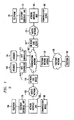
- FIG. 1 illustrates a network according to an embodiment of the present invention.
- Network 10 includes communication network 100 which is connected to gate controller 110 and gate controller 111, network edge devices 120 and 121, and telephone network gateway 130.
- Gate controllers 110 and 111 are connected to database storage 140 and 141, respectively.
- Network edge devices 120 and 121 are connected to access networks 150 and 151, respectively.
- Access networks 150 and 151 are connected to network interface units 160 and 161, respectively.
- Network interface units 160 and 161 are connected to telephone interface units (TIUs) 170 and 171, respectively, and communication devices 180 and 181, respectively.
- TIUs 170 and 171 are connected to telephones 190 and 191, respectively.
- Telephone network gateway 130 is connected to telephone network 135 which, in turn, is connected to telephone 192.
- Communication network 100 can be a network that supports, for example, Internet Protocol (IP) signaling, IP media transport, and/or asynchronous transfer mode (ATM) media transport.
- Access networks 150 and 151 can be networks of wires or fibers capable of carrying voice and/or data transmissions.
- the telephone network 135 can be, for example, the Plain Old Telephone System (PSTN).
- PSTN Plain Old Telephone System
- Network interface units 160 and 161 can be, for example, cable modems designed for use on a television coaxial cable circuit.
- Network interface units 160 and 161 allow communication devices 180 and 181, respectively, to connect to access networks 150 and 151, respectively.
- Network interface units 160 and 161 also allow TIUs 170 and 171, respectively (and in turn telephones 190 and 191, respectively), to connect to access networks 150 and 151, respectively.
- Network edge devices 120 and 121 are devices located at the edge of the communication network 100 that connects the communication network 100 to the access networks 120 and 121, respectively.
- the network edge devices can be, for example, routers or bridges or similar equipment that can connect communication network 100 to access networks 150 and 151. Because NEDs 120 and 121 can be specifically implemented as, for example, routers at the network edge, these units are also referred to herein as edge routers (ERs).
- ERs edge routers
- Network edge devices 120 and 121 can implement resource management and admission control mechanisms that allow the communication network 100 to provide assurances of bounded per-packet loss and delay required to assure an authorized quality of service for a call.
- network edge devices e.g.,network edge devices 120 or 121
- the network edge devices can ensure that enhanced quality of service for a call of a particular party has been authorized and for which usage accounting is being done.
- Network edge devices can generate accounting records for calls because these devices track the resource usage within the communication network 100 for the calls.
- Network edge devices can also implement Network Address Translation to support address privacy for called paries and/or calling parties, as described more fully below.
- TIUs 170 and 171 are gateways between telephones and packet-carrying networks, such as access networks 150 and 151 and communication network 100.
- TIUs 170 and 171 can digitize, compress and packetize voice signals from telephone 190 and 191, respectively, to convert analog voice into data packets for transport over the communication network 100, and vice versa.
- TIUs 170 and 171 can be, for example, a simple stand-alone telephony device that incorporates the broadband interface, a high-speed data cable modem that incorporates the interface unit (i.e., TIUs and their associated network interface units can be combined into a single device), or an advanced digital set-top box that incorporates the broadband interface.
- TIUs 170 and 171 can be for example broadband interfaces for telephones; consequently, these units are also referred to herein as broadband telephony interfaces (BTIs).
- BTIs broadband telephony interfaces
- TIUs contain sufficient processing and memory to perform signaling and call control functions. More specifically, TIUs 170 and 171 each include a processor and is capable of detecting changes in state information (e.g., hook state detection), collecting dialed digits (e.g., dual-tone multifrequency (DTMF) signals), and participating in the implementation of telephone features for telephones 190 and 191, respectively. TIUs 170 and 171 can also participate in end-to-end capability negotiation as described below.
- state information e.g., hook state detection
- DTMF dual-tone multifrequency
- end-to-end refers the association between two end points-for a call.
- the end-to-end association for the call can be between the two telephony interface units.
- end-to-end messages for example would include messages originating at one telephone interface unit and terminating at the other telephony interface unit where the messages are opaque to other network entities that merely forward the messages (possibly after performing network address translation as described below).
- end-to-end messages can be routed between telephone interface units with messages being forwarded by the network edge devices and without the message being routed through the gate controllers.
- the end-to-end association for the call can be between the calling party telephony interface unit and the called party network interface unit.
- TIUs can maintain information for calls while in progress, thereby implementing certain service features locally. For example, call waiting can be implemented locally, by detecting hook flash and controlling the active call. Similarly, return call can be implemented locally by retaining state information in the TIUs about the most recent calls.
- TIUs 170 and 171 are considered to be "untrusted" devices in the sense that the TIUs can operate locally-stored software and are not necessarily under the direct control of the service provider (e.g., the entity operating the communication network 100). Because the TIUs are untrusted devices, information passed to the TIUs can be first encrypted before it is given to the TIUs to guarantee privacy. For example, state information can be passed from the gate controllers 110 and/or 111 to the TIUs which store the state information for their later use (thereby avoiding the need to maintain state information for a call at the gate controllers) by first encrypting the state information; the state information retrieved from the TIUs can be verified subsequently via known encryption techniques.
- a cryptographic hash function can be applied to the state information to detect the integrity of the state information (i.e., detect whether the state information has been altered by an untrusted entity).
- a cryptographic hash value is produced which can be sent to and maintained by the TIUs.
- the cryptographic hash function can be applied to this retrieved state information; if the same hash value is produced, then the retrieved state information has not been altered at, for example, the TIU.
- the cryptographic hash functions can be, for example, a modification detect codes (MDCs) or message authentication codes (MACs). '
- Gate controllers 110 and 111 are adjunct platforms that have access to authentication databases and customer profile information on database storage 140 and 141, respectively. Gate controllers 110 and 111 implement a set of service-specific control functions to support communication services, such as authentication and authorization, number translation and call routing, service-specific admission control, and signaling and service feature support.
- the gate controllers can authenticate signaling messages and authorize requests for service so that communication services and certain service features are only provided to authorized subscribers. In other words, upon receiving a setup request message from a calling party, the gate controller can authenticate the identity of the calling party and authorize the service sought by the calling party.
- the gate controllers can translate dialed telephone numbers to communication network addresses (such as, for example, IP addresses) based on call routing logic. For example, an originating gate controller (e.g., gate controller 110) can translate a dialed telephone number to a communication network address associated with the terminating gate controller (e.g., gate controller 111). The terminating gate controller can subsequently translate the communication network address to the terminating end-point (e.g., BTI 171) to which the call should be routed. In an alternative embodiment, a single dial telephone number can be mapped to multiple communication network addresses, for example, to allow the signaling and media end-points associated with a call to be distinct.
- communication network addresses such as, for example, IP addresses
- the gate controllers can implement a broad range of service-specific admission control policies for the communication services. For example, the gate controllers can provide precedence for particular call (e.g., 911 emergency calls).
- the gate controllers can perform admission control to implement overload control mechanisms similar to those used in the conventional telephone network (e.g., telephone network 135), for example, to restrict the number of calls to a particular location or to restrict the frequency of call setup to avoid signaling overload. These mechanisms can be invoked either dynamically or under administrative control.
- the gate controllers can perform signaling and service feature support where the service features cannot be supported solely by the TIUs. For example, certain service features such as call transfer require changing the end-points participating the calls; in such a case, the gate controllers change the gate parameters because call transfer requires reauthorization by the gate controllers. Service features that depend on the privacy of the calling information, such as caller-ID blocking, are implemented by the gate controllers. In addition, service features that require users to receive a consistent view of feature operation even when a TIU is inoperative are implemented by the gate controllers. For example, the gate controllers can control call forwarding when a TIU for a call is inoperative.
- Gate controllers can be organized in domains where each gate controller is associated with a set of TIUs and the network edge devices that serve those TIUs. Although the TIUs are not trusted entities, a trust relationship exists between an network edge device and its associated gate controller because the gate controller acts as a policy server controlling when the network edge device can provide enhanced quality of service. A trust relationship can also exist between gate controllers.
- a gate controller can act as a simple transaction server so that a failure of a gate controller does not affect associated calls that are in process.
- a gate controller domain can include a primary and a secondary gate controller. If the primary gate controller fails, only calls in a transient state are affected (i.e., calls that are being established including, for example, where network resources are being allocated). The TIUs associated with those affected calls in a transient state will try to be established on the secondary gate controller after a timeout period has elapsed. All active calls (i.e., calls in progress) are unaffected by the failure of a primary gate controller because the gate controller does not retain state information for these stable, active calls. As a result, gate controllers easily and efficiently scale as more gate controllers for the communication network are required.
- Telephone network gateway 130 can include a combination of a trunking gateway (not shown) and a signaling gateway (not shown).
- the trunking gateway can convert between a data format used on the data network 100 and the pulse code modulation (PCM) format typically used for transmission over the telephone network 135.
- PCM pulse code modulation
- the signaling gateway can provide signaling internetworking between signaling protocols of embodiments of present invention described below and conventional telephony signaling protocols such as ISUP/SS7 (i.e., Integrated Services Digital Network User Part / Signaling System 7).
- a media gateway control protocol can be used to control the operation of a media gateway separate from a signaling gateway.
- additional network entities can be included in the network 10.
- the gate controllers can use other servers to implement the authorization or the translation functions.
- three way calling can be supported using audio bridges in the network 10.
- network 10 can be included in network 10.
- sole network interface unit e.g., a cable modem
- multiple network interface units are likely connected to each access network.
- network edge devices e.g., a few gate controllers and a sole telephone network gateway
- many such devices can be connected to the communication network 100.
- Many other variations to the network 10 shown in FIG. 1 are possible.
- network resources for a call between a calling party and a called party are allocated.
- the network resources for the call are reserved based on a reservation request.
- the network resources are reserved before any one network resource from the reserved network resources is committed.
- the reserved network resources for the call are committed when a called party indicates acceptance for the call.
- Network resources is used herein as the facilities of a communications network required for a call and any auxiliary services associated with that call.
- Network resources can include, for example, the capabilities or capacities of equipment within the communications network needed to establish and maintain a call at an appropriate quality of service.
- the equipment within the communications network can include, for example, routers, bridges and gateways within the communications network.
- the called party "indicates acceptance" for the call in a number of ways. For example, where the called party is using a telephone 190, the called party can indicate acceptance for the call by picking up the telephone hand set thereby causing an off hook condition. Where the called party is using a communication device 181 (e.g., a personal computer), the called party can indicate acceptance by making an appropriate selection with the communication device 181 that initiates handshake signaling (i.e., a personal computer equivalent for an off-hook condition). Where the called party has an answering machine, the answering machine timer can expire to connect the call.
- a communication device 181 e.g., a personal computer
- Network resources are "reserved" in the sense that the network resources required for a particular call can be identified before the called party is actually connected to the calling party. These network resources can be reserved through the appropriate signal messages collectively referred to herein as a "reservation request". After the appropriate network resources have been reserved based on the reservation request, these network resources are committed when the called party indicates acceptance for the call. By committing the network resources only when the called party indicates acceptance for the call, the accounting for the call can, for example, accurately track the time of the actual call while excluding the time of the call setup.
- Network resources are "committed" in the sense that an available network resource operates such that the voice information between the calling party and the called party is transported. Before the network resources are committed, the network resources are allocated for the call but are not configured to actually carry the voice information for the call. By committing the reserved network resources once the called party indicates acceptance for the call, the network resources are not wastefully configured before they are actually needed. This can be particularly relevant for portions of the communication network where resources are limited, such as, for example, the upstream resources within the cable network.
- the term "quality of service” is used herein to include, but not limited to, the measure of telecommunication service quality provided during a call.
- the quality of service can be specified by a calling party, a called party or the service provider of the communications network, or any combination thereof.
- the quality of service is "authorized" in the sense that the calling party and/or the called party specify a quality of service for the call and the service provider can verify the specified quality of service for the call.
- a calling party transferring data may subscribe for a service with a quality of service having a large bandwidth and small latency; in such an example, a service provider can verify the service subscription for the particular quality of service associated with the call for that particular calling party.
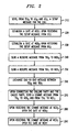
- FIG. 2 illustrates a flow chart to reserve network resources for a call, according to an embodiment of the present invention.
- FIG. 2 is a simplified view of the connection process to better illustrate the two-phase allocation of network resources. This process is in two phases in the sense that network resources are first reserved and then committed in separate and distinct phases. In other words, network resources are reserved first; once the reservation process is complete, then the reserved network resources can be committed. Other aspects of the overall process will be described in further detail in other sections below.
- originating TIU 170 originating network edge device 120 (NED O )
- originating gate controller 110 originating gate controller 110
- GC T terminating gate controller 111
- terminating network edge device 121 NPD T
- terminating TIU 171 TU T
- a setup message for a call between a calling party and a called party is sent from the originating TIU 170 to the originating gate controller 110 and the terminating gate controller 111.
- the setup message (possibly modified with additional information) can be forwarded to the terminating gate controller 111 through communication network 100.
- the setup message can be, for example, in the form of the SETUP message described below in Section 7 entitled "Protocol Description".
- a gate for the call is established at the terminating network edge device 121 upon receiving the setup message from terminating gate controller 111.
- a "gate” is a call-admission control mechanism that uses, for example, known packet filters at the edge routers.
- another gate for the call is established at the originating network edge device 120.
- the gates can have associated time limits on the gate duration; such a features can allow the calls to be limited where, for example, the calls are established with a pre-paid calling card that has a limited amount of calling time that is pre-paid.
- the state information for the call is maintained at a network entity through which the call is routed.
- state information for a call can be maintained without maintaining the state information at a gate controller. Consequently, if a gate controller fails after the gates have been established for a call, the call can be maintained.
- the establishment of gates for a call are discussed more fully below in the Section 4 entitled "Gate Coordination on a Per-Call Basis".
- a reserve message is sent from the originating TIU 170 to the originating NED 120.
- a reserve message is sent from the terminating TIU 171 to the terminating NED 121.
- the reserve messages sent by the originating TIU 170 and terminating TIU 171 are a part of the reservation process where an allocation of network resources is requested but the network resource need not yet be assigned or committed. Allocating the network resources includes the verifying that the quality of service desired by a TIU is no greater than the quality of service authorized by the corresponding gate controller; the gate controller authorizes a quality of service for a call using the authentication databases and customer profile information on the associated database storage (e.g., database storage 140 and 141).
- the network 10 can provide bounded per-packet loss and delay for the voice packets of a call by performing active resource management both in the access network 150 and 151, and communication network 100. Because the network edge devices (e.g., NEDs 120 and 121) within the connection path for a call may have capacity constrained links, reservation requests for a call (and any associated messages) are forwarded end to end, thereby ensuring that network resources are available end to end. In one embodiment, because the access networks 150 and 151 may be capacity constrained (at least in the upstream direction), resource management is performed on a per-call basis for the access networks 150 and 151.
- the network edge devices e.g., NEDs 120 and 121
- the access networks 150 and 151 may be capacity constrained (at least in the upstream direction)
- resource management is performed on a per-call basis for the access networks 150 and 151.
- Resource management in the communication network 100 can be performed on a per-call basis or on a coarse-grained resource basis (i.e., resources within the communication network 100 can be reserved for multiple calls at a given time). Resource management within portions of the communication network 100 may be performed on a per-call basis because some network edge devices with the communications network 100 may not have sufficient processing capacity to process a large number of reservation messages typical for high volume call traffic. Alternatively, resource management within portions of the communication network 100 may be performed on a multiple-call basis if these portions of the communication network 100 are adequately provisioned (i.e., sufficient capacity has been reserved by a multiple-call reservation); in such cases, network edge devices within these portions of communication network 100 need not perform per-call admission control. Consequently, in an embodiment of the present invention, some network edge devices do per-flow admission control to interpret reservation requests while other network edge devices that are in capacity-rich regions of the data network 100 are provisioned to simply forward these messages without interpretation.
- Embodiments of the present invention can perform resource reservation in the communication network 100 in a uni-directional manner which thereby compensates for routing asymmetries.
- the originating TIU 170 sends a reservation request to the originating NED 120 and when the originating TIU 170 receives back an acknowledgment for the reservation request, two aspects are of the connection are confirmed. First, adequate bandwidth for the call is available in both directions over the access networks 150 and 151. Second, adequate bandwidth for the call is available over the communication network 100.
- Steps 210 through 250 describe the process of reserving the network resources. At this point, the network resources to be used for the call are reserved, but none of these network resources are yet committed.
- end-to-end messages are exchanged between the originating TIU 170 and the terminating TIU 171.
- end-to-end refers the associated between two end points associated with a call. So, where a call involves a calling party and a called party using telephones, the end-to-end association for the call can be between the two telephony interface units; thus, end-to-end messages would include messages originating at one telephone interface unit and terminating at the other telephony interface unit.
- the end-to-end messages can include, for example, a ring message from the originating TIU 170 to the terminating TIU 171, a ring back message from the terminating TIU 171 to the originating TIU 170, and a connect message from the terminating TIU 171 to the originating TIU 170.
- the ring message can signal the terminating telephone 191 to ring thereby indicating an incoming call.
- the ring back message can signal the originating TIU 170 that the terminating telephone 190 is ringing.
- the connect message can signal to the originating TIU 170 that the called party has indicated acceptance for the call by, for example, going off-hook. Note that these end-to-end messages can be routed between the originating TIU 170 and the terminating TIU 171 without being routed through the originating gate controller 110 or terminating gate controller 111.
- a commit message is sent from the originating TIU 170 to the originating NED 120 and from the terminating TIU 171 to the terminating NED 121.
- the gate established at the originating NED 120 in step 230 is opened.
- the gate established at the terminating NED 120 in step 220 is opened.
- the commit process can include a verification by the NED that the actual quality of service sought by the associated TIU is no greater than the quality of service reserved during the reservation process.
- the gate at the originating edge router and the gate at the terminating edge router for each call are opened almost simultaneously (e.g., within a few hundred milliseconds of each other) because, under normal operating conditions, the calling party and the called party send respective Commit message to their respective network edge devices substantially simultaneously. Similarly, under normal operating conditions, the calling party and the called party end the call and send respective release messages to their respective network edge devices substantially simultaneously. Gate coordination prevents billing for incomplete calls and prevents theft of service by two colluding BTIs.
- embodiments of the present invention advantageously ensure that network resources are available before actually ringing the far-end telephone (e.g., the telephone of the called party). This, of course, advantageously ensures that usage recording is not initiated until the far-end telephone goes off hook. Consequently, call billing excludes calls that are not completed (e.g., where the called party does not answer) and excludes the portion of calls that occur before the called party answers.
- FIG. 2 describes an embodiment for reserving network resources where the calling party and the called party were using telephones 190 and 191, respectively, through TIUs 170 and 171, respectively, the process can be analogized for a calling party and/or called party using a communication device 180 and/or 181, respectively.
- a gate setup message for a call (e.g., a GATESETUP message described in Section 7 below) is received through a network edge device connecting a trusted network to an untrusted network.
- the state information for the call (e.g., contained within a GATEALLOC message described in Section 7 below) is formatted at the gate controllers based on the setup message for the call.
- the state information for the call is sent to the originating network edge device without maintaining the state information at the originating gate controller and at the terminating network edge device without maintaining the state information at the terminating gate controller.
- the term "maintained" as used herein in reference to the state information is intended to include storing and using the state information while the call is being established, the call is in progress and the call is being released.
- the state information may be temporarily stored at the gate controllers, the state information is not maintained at the gate controller because the gate controllers do not use the state information (e.g., for call processing) while the call is being established, the call is in progress and the call is being released.
- the gate controllers need not store the state information after the state information has been provided to the network edge routers because the state information for the call is accessed at the network edge devices, not the gate controllers:
- signaling messages are exchanged for a call between a calling party to a called party in two phases.
- the signaling messages are exchanged in two phases in the sense that the messages for setting up the call are exchanged in one phase and the messages for connecting the call are exchanged in a separate and distinct second phase.
- the later messages can be exchanged end to end without being routed through the gate controllers that set up the call.
- two-phase signaling is distinct from the concept of two-phase network resource reservation in the sense that the two-phase signaling can be performed in combination with or independent of the two-phase network resource reservation.
- the messaging for the two-phase signaling can be interleaved with the messaging for the two-phase network resource reservation; when done independently, the messages for each can be distinct.
- the two-phase network resource reservation relates to reserving network resources without committing them, then committing those reserved resources.
- the two-phase signaling relates to performing signaling to set up the call, then once the call is setup (e.g., thereby confirming the authoried quality of service), exchanging end-to-end messaging.
- a setup message having a destination address is forwarded from the calling party to the called party.
- a setup acknowledgment message is received at, for example, a gate controller from the called party if the destination address corresponds to the called party.
- the received setup acknowledgment message is sent to the calling party.
- the calling party and the called party exchange end-to-end messages if the calling party received the forwarded setup acknowledgment message and if at least one from the group of the called party and the calling party sent a reserve message to an associated network edge device.
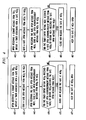
- FIG. 3 illustrates a flow chart for performing two-phase signaling in call connection, according to an embodiment of the present invention.
- the calling party goes off-hook and dials a telephone number of the called party.
- FIG. 3 will be discussed where the calling party is using telephone 190 and the called party is using telephone 191.
- the originating TIU 170 collects the dialed digits.
- the originating TIU 170 sends a setup message to the originating gate controller 110.
- the setup message can be sent through network interface unit 160, access network 150, NED 120 and communication network 100.
- the setup message can be, for example, in the form of the SETUP message described below in Section 7 entitled "Protocol Description".
- the setup message is forwarded from the originating gate controller 110 to the terminating gate controller 111.
- the setup message is forwarded from the terminating gate controller 111 to the terminating TIU 171. (After receiving the setup message, the originating gate controller 110 and the terminating gate controller 111, can establishe a gate at the originating NED 120 and a gate at the terminating NED 121 as described in Section 2 above.)
- a setup acknowledgment message is sent to the TIU 170.
- the setup acknowledgment message can be sent, for example, through terminating gate controller 111 and originating gate controller 110.
- the setup acknowledgment message can be, for example, in the form of the SETUPACK message described below in Section 7 entitled "Protocol Description".
- the network resources for the call are reserved.
- a reserve message is sent from the originating TIU 170 to the originating NED 120 and from the terminating TIU 170 to the terminating NED 121 when an allocation of network resources is requested but the network resource need not yet be assigned or committed.
- end-to-end messages are exchanged between the originating TIU 170 and the terminating TIU 171 if the calling party received the setup acknowledgment message sent to the originating TIU 170 in step 360 and if the calling party or the called party sent a reserve message to its NED.
- end-to-end messages relating to the connection of the call are exchanged only after the reservation messages have been exchanged and the reservation process is complete. This ensures that service is only provided,to calling and called parties that have been authorized and authenticated for the call. This also ensures that the call is established for a specifically authorized quality of service and that the call is billed appropriately.
- a ring message is sent from the originating TIU 170 to the terminating TIU 171.
- the ring message can signal the terminating telephone 191 to ring thereby indicating an incoming call.
- a ring back message is sent from the terminating TIU 171 to the originating TIU 170.
- the ring back message can signal the originating TIU 170 that the terminating telephone 190 is ringing.
- a connect message is sent from the terminating TIU 171 to the originating TIU 170.
- the connect message can signal to the originating TIU 170 that the called party has indicated acceptance for the call by, for example, going off-hook.
- end-to-end messages can be routed between the originating TIU 170 and the terminating TIU 171 without being routed through the originating gate controller 110 or terminating gate controller 111 because state information for the call can be maintained without maintaining it at the gate controllers 110 and 111.
- end-to-end message can be routed through NEDs 120 and 121 opaquely.
- the gate controllers are involved in the signaling process where only needed: during the reservation process.
- the originating and terminating gate controllers pass the state information for the call to, for example, the originating and terminating TIUs without maintaining the state information at the gate controllers.
- the gate controllers no longer need be involved in the call and messaging related to the connection process can be sent end-to-end without being routed through the gate controllers.
- the gate controllers are involved only during the initial start of the call but not during the call duration. This results in a reduction of the message load by, for example, approximately a factor of three. Consequently, the amount of memory need in the gate controllers is greatly reduced.
- the gate controllers can be constructed without the typically stringent requirements for reliability.
- reserved network resources can be committed upon the originating and terminating network edge devices receiving commit messages indicating that the call has been connected.
- gates associated with a call between a calling party and a called party can be opened in a coordinated fashion.
- a timer associated with a first gate opened at an originating network edge device is initiated.
- a first gate open message is sent from the originating network edge device to the terminating network edge device.
- the first gate at the originating network edge device is released if the timer expires before at least one from the group of: (1) an acknowledgment based on the sent first gate open message is received from the terminating network edge device, and (2) a second gate open message is received at the originating network edge device from the terminating network edge device after the terminating network edge device has opened a second gate associated with the called party.
- a timer associated with a gate at the originating NED 120 is initiated upon receiving a commit message from the originating TIU 170.
- a timer associated with a gate at the terminating NED 121 is initiated upon receiving a commit message from the terminating TIU 171.
- the commit message is sent from a TIU to the associated NED upon the called party indicating an acceptance for the call (e.g., by a connect message being sent from the terminating TIU to the originating TIU).
- the order steps 400 and 410 depends on the order in which the NEDs receive the commit messages from their associated TIUs.
- a gate open message is sent from the originating NED 120 to the terminating NED 121.
- a gate open message is sent from the terminating NED 121 to the originating NED 120.
- the setup acknowledgment message can be, for example, in the form of the GATEOPEN message described below in Section 7 entitled "Protocol Description". The order in which steps 420 and 430 are performed depends on the order in which steps 400 and 410 are performed.
- a gate open message is sent from one NED to the other NED to notify that other NED when a gate for the call has been opened.
- a gate open acknowledgment message is sent from originating NED 120 to terminating NED 121 upon the originating NED 121 receiving the gate open message sent during step 430 by terminating NED 120.
- a gate open acknowledgment message is sent from terminating NED 121 to originating NED 120 upon the terminating NED 120 receiving the gate open message sent during step 420 by originating NED 120.
- the setup acknowledgment message can be, for example, in the form of the GATEOPENACK message described below in Section 7 entitled "Protocol Description". The order in which steps 440 and 450 are performed depends on the order in which the gate open acknowledgment message are received.
- a gate is "closed" in the sense that the call is no longer active although the gate for the call remains established for possible later use.
- a first party can be connected to two other parties and two gates (one per call) will be established at the network edge device associated with the first party.
- the temporarily inactive call will have an associated gate that is closed; this closed gate can be reopened upon the call being reactivated.
- a gate is "released" in the sense that the call is no longer active and the gate for the call is deleted from the associated network edge device. In such a case, for a call to be started, the entire network resource reservation process and commit process (see, e.g., the discussed relating to FIG. 2 ) have to be repeated.
- the timer at a gate ensures that the other gate related to the call is also opened within the timer period so that billing for the call is accurate and so that theft of service can be prevented. Without such gate coordination, either a service provider could bill a party for a call where only one gate was opened (even if the calling party was not connected to the called party) or a service provider could be susceptible to theft of service for a call where only one gate was opened.
- Gate coordination can also be performed at the end of a call. Just as a gate open message and a gate open acknowledgment message is sent to the network edge device where the peer gate is established, a gate close message and a gate close acknowledgment message can be sent upon a gate closing to the network edge device where the peer gate is open.
- a gate close message and a gate close acknowledgment message can be sent upon a gate closing to the network edge device where the peer gate is open.
- the originating TIU 170 calls terminating TIU 171 and pays for the call. If either the calling party or the called party end the call, the gates at both the originating NED 120 and the terminating NED 121 need to be closed. Because the originating TIU 170 is being billed for the call, the calling party has an incentive to issue a release message to close the gate at the originating NED 120. The terminating TIU 171, however, cannot be trusted to send the release message to close the gate at the terminating NED 121. A gate close message sent from the originating NED 120 can close the gate at the terminating NED 121 to prevent the terminating TIU 171 from placing another call and having that call billed to the party associated with TIU 170.
- any information that a calling party or a called party desires to keep private should be accessible to the network 10 but not to other untrusted entities.
- This section describes the use of network address translations and encryption techniques that allow gate controllers to send state information to TIUs where it is maintained in a form that renders the private information opaque.
- a call between a calling party and a called party is connected.
- Information associated with the call is sent from the calling party to the called party without the-called party receiving a source address that indicates at least one from the group of a logical identity of the calling party and a geographical identity of the calling party.
- logical identity is used to herein to include, for example, any aspect of the source address or destination address that indicates the specific identity of a calling party or the called party.
- geographic identity is used to herein to include, for example, an aspect of the source address or destination address that indicates the particular geographic location of a calling party or called party. Even where a network address has been modified or altered to protect the logical identity of a calling party or called party, the remaining aspects of the network address can reveal the general geographic location of the party. In an embodiment of the present invention, information is sent from one party to another party without revealing either the logical identity nor the geographic identity of a party.
- FIG. 5 illustrates a flow chart for translating a network address, according to an embodiment of the present invention.
- packets having the source address and the destination are sent from the originating TIU 170 through the originating network interface unit 160 towards the originating NED 120.
- the source address and the destination address locally identify the calling party and the called party, respectively. These addresses are. "local" in the sense that they are associated with particular portions of networks (also referred to herein as "address domains”), such as portions of the access network 150 and/or communication network 100 and/or other access networks (not shown in FIG. 1 ). These local addresses are not sent outside of their resepective address domains.
- Table 1 illustrates an example of the source address (SA) and the destination address (DA) at this point.
- SA 10.10.1.5
- DA 10.10.1.27
- the packets received at NED 120 are translated from local addresses for the address domain within access network 150 to global addresses. Not only can the destination address be translated into a global address, but the source address can also be translated into a global address.
- Table 2 illustrates a translation table for the call used at NED 120. Note that the global addresses used for the call can be assigned dynamically, for example, on a call-by-call basis so that when a call has ended, the global address can be reused for another, unrelated call.
- the packets are forwarded from the originating NED 120 to the terminating NED 121.
- the packets have the global address shown in Table 2.
- the packets received at the terminating NED 121 are translated from global addresses to addresses that are local to the address domain for which the terminating access network 151 is included.
- Table 3 illustrates a translation table for the call used at NED 121 for translating the global addresses to local addresses.
- Table 3 Global Address Local Address 135.4.1.7 10.10.100.19 SA 135.4.2.15 10.10.100.7 DA
- the packets translated by the terminating NED 121 are sent through access network 151 to the terminating TIU 171.
- Table 4 illustrates the source address and the destination address for the packets for the call as the packets are transmitted across terminating access network 151, through terminating network interface unit 161 to the terminating TIU 171.
- Table 4 SA 10.10.100.19 DA 10.10.100.7
- the translated packets are received at the terminating TIU 171 without revealing the logical identity and the geographic identity of calling party. Note that the called party only has access to the global source address and the global destination address which themselves are translations. Because the source address of calling party has been translated twice, once at the originating NED 120 and once at the terminating NED 121, address information about the calling party has been altered beyond recognition to the calling party.
- the translation tables at the originating NED 120 and the terminating NED 121 can be deleted, and the global addresses can be released for reuse in another call.
- the global addresses can be released when the gates are released.
- the global addresses can be released after a time period of inactivity.
- FIG. 5 illustrates the process by which packets are sent from the originating TIU 170 to the terminating TIU 171.
- packets sent from the terminating TIU 171 to the originating TIU 170 can be translated at the terminating NED 121 (reverse of the translation shown in Table 3) and again at the originating NED 120 (reverse of the translation shown in Table 2).
- the source address and the destination address of the packets can be sent from the terminating TIU 171 to the originating TIU 170 without revealing the logical identity and the geographic identity of called party.
- the double translation of network addresses can be provided as a service to a subscriber by a service provider.
- a call can be connected where the calling party and/or the called party subscribe to the double translation service.
- FIG. 5 illustrates the case where the privacy of both the calling party and the called party address information is maintained: both the source address and the destination address of packets for the call are translated as the packets are sent from the calling party to the called party and as packets for the call are sent from the called party to the calling party.
- the double translation service can be provided to one party (i.e., only the calling party or the called party) without providing the service to the other party.
- the first source address for packets sent from the originating TIU 170 are translated at the originating NED 120 into a global source address, and the global address for these packets are translated at the terminating NED 121 into a second local source address.
- the second local source address is translated at the terminating NED 121 into the global source address
- the global source address is translated into the first source address at the originating NED 120.
- the translation tables at the originating NED 120 and the terminating NED 121 can be set up for a specific call and then can be deleted at the end of the call. This further ensures the privacy of the calling party and/or called party because the global addresses are not repeated. Furthermore, by releasing the global addresses at the end of a call, the global addresses can be reused for another call having a different calling party and/or called party. Consequently, any potential shortage in the number of global addresses can be alleviated because the number of active calls at one time is much less than the number of total calling parties and called parties.
- a ringback for a call between a calling party and a called party can be simulated.
- a connection acknowledgment associated with the call is received where the calling party is located within a first network and the called party is located within a second network.
- a prestored ring back signal from a set of prestored ringback signals is selected where the selected prestored ring back signal is associated with the second network. The selected prestored ring back signal is sent to the calling party.
- the prestored ringback signal can be, for example, a signal that is indicative of the network associated with the called party rather than a signal originated by that network.
- a signal indicative of a foreign network i.e., a network located in a foreign country
- the ring back signal can simulate the ring back signal for that foreign country rather than relying on the actual foreign-network-originated ring back signal.
- call flows are presented to show the signaling exchange for both basic telephony services as well as many CLASS and Custom Calling features.
- Signaling call flows that can be used by embodiments of the present invention.
- Symbols are used to represent parties involved in the call flow (e.g. Gate Controllers) and information that is exchanged (e.g. Call Parameters). Each of these is often followed by a subscript indicating which one specifically is being referenced. Common subscripts are O for originating, T for terminating, F for forwarding, B for bridging, and TR for transferring.
- BTI O refers to the originating BTI
- BTI T to the terminating BTI, and similarly for E.164 T , ER O , ER T , GC O , GC T , etc.
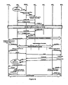
- FIG. 6 shows the call flow for a normal call setup, according to an embodiment of the present invention.
- Call setup involves establishing an IP signaling and bearer channel between BTIs across a packet network.
- the signaling channel uses "better than best effort” IP transmission across the network. Signaling reliability is ensured within the application.
- the bearer channel uses an "unsolicited grant" as defined by the MCNS v1.1 to maintain a constant bit rate channel.
- the ER "colors" the "high QoS" bearer channel packets to give them higher priority than "best-effort QoS” packets over the backbone portion of the network (between the ERs).
- Figure 7 shows an example signaling call flow for reservation of resources in the segment of the network between the edge routers for a voice call, according to an embodiment of the present invention.
- This is one potential model of backbone reservation; however, different approaches may achieve the same result.
- a separate the mechanism for access reservation from the backbone reservation is used. This leaves the BTI interaction with the ER independent of the backbone network between ERs.
- the resource reservation is initiated by a sender and only reserves resources for packets being generated by that sender i.e. reservations are unidirectional. This matches the forwarding model used in IP networks in which paths can be asymmetric. However, the RESERVE message used over the access network has different semantics: reserve bi -directional capacity over the access network.
- the IP source address in the RESERVE message contains the source address of ER o .
- the IP destination address in the RESERVE message is that of BTI T .
- the reservation message identifies: GA O (BTI O 's global IP address), PN O (BTI O 's port number for this call), GA T (BTI T 's global IP address), PN T (BTI O 's port number for this call) as the owner of the reservation.
- the ER After setting up the bi-directional access reservation, the ER sends a BACKBONERESERVE message through intermediate backbone routers towards BTI T . Routers that are incapable of processing the BACKBONERESERVE message forward them without any processing.
- the receipt of the RESERVEACK to a BTI indicates that resources have been reserved in both the send and receive directions in the access channel, and in the send direction in the backbone.
- Figure 8 shows the call flow for a normal call termination, according to an embodiment of the present invention.
- a BTI detects on-hook, it sends an end-to-end HANGUP message to the other BTI and a RELEASE message to the ER.
- the ER closes the gate and emits a CALLEND to the billing system that indicates the call has completed and that billing should stop.
- FIG 9 shows the call flow for a call originating from a BTI but terminating in the PSTN, according to an embodiment of the present invention.
- GC T recognizes that E.164 T terminates outside of the IP network.
- GC T identifies the appropriate SGW T and TGW T .
- GC T initiates a GATESETUP to ER T with the Cut Through On Reserve (CTOR) flag set to indicate that a one-way voice path from the PSTN to BTI o should be established once the reserve is requested.
- GC T then sends the SETUP to SGW T .
- SGW T allocates a trunk identified by the IP port number PN T on TGW T for the call.
- SGW T also looks at CP O to determine the call parameters that will be used for this call (CP T ).
- GC T Upon receiving the SETUPACK from SGW T , GC T replies to GC O , including the CTOR flag. GC O sets up the gate on the originating end of the call including the CTOR flag indicating that ER O , should open the voice path toward BTI O on reserve. GC O also includes the CTOR flag on the SETUPACK message to BTI, so BTI O does not generate its own ringback, but uses the ringback from the far end of the network. If additional capability negotiation is needed, it can be done at this point.
- SGW T uses the SGCP message CREATECONNECTION to inform TGW T about the potential call. Included in this message are all the parameters that TGW T needs to reserve the necessary bandwidth and to translate between the IP packets and the TDM trunk. Also included in this message is an SGCP NOTIFICATIONREQUEST, requesting TGW T to notify SGW T when the reservation is acknowledged by ER T . TGW T sends a reserve message requesting the appropriate QoS in the network for the call. The trunking gateway needs to send this reserve message (versus the SGW) since the reservation needs to be along the path of the bearer channel. Upon a successful reservation, TGW T sends the SGCP NOTIFY to SGW T .
- SGW T receives both the RING message from BTI O and the NOTIFY from TGW T , SGW T sends the SS7 Initial Address Message (IAM) into the PSTN to set up the connection between TGW T and the ultimate destination.
- IAM Initial Address Message
- ACM SS7 Address Complete Message
- SGW T sends BTI O the RINGBACK message and BTI O plays ringback tone it is receiving from the network to the customer.
- SGW T When the destination phone goes off-hook, an SS7 Answer Message (ANM) is received by SGW T .
- SGW T sends the CONNECT back to BTI o and uses the SGCP message MODIFYCONNECTION to indicate to TGW T that it needs to change the connection to a two-way connection, and send the COMMIT into the network to open the gate in both directions.
- FIG 10 shows the call flow for a call originating in the PSTN, but terminating in the IP telephony network, according to an embodiment of the present invention.
- the IAM message is the first indication that a call is destined from the PSTN to a BTI.
- the IAM message is received by SGW O which subsequently sends a SETUP message to GC O . setup proceeds as normal through the IP network.
- the CTOR flag is not needed since ringback or terminating announcements will not be generated from the IP network.
- the signaling flow is similar to when a call is destined for the PSTN (see previous section).
- SGCP messages are used between SGW O and TGW O .
- FIG 11 shows the call flow for a normal release to the PSTN, according to an embodiment of the present invention.
- This call flow assumes that the BTI originated the call. If the call originated in the PSTN, SGW T would send an SS7 Suspend (SUS) message. This indicates to the PSTN that the phone at the BTI went on-hook, but the call is not released until a timer expires (for example, 14 seconds). If the phone goes off-hook before the timer expires, an SS7 Resume (RES) message is sent.
- SUS SS7 Suspend
- Figure 12 shows the call flow for a call released from the PSTN, according to an embodiment of the present invention.
- the call flow assumes that the call originated in the PSTN.
Abstract
Description
- This application claims the benefit of
U.S. Provisional Application No. 60/104,878, filed October 20, 1998 U.S. Provisional Application No. 60/095,288, filed August 4, 1998 - This application is related to the following pending, commonly assigned patent applications filed on the same day: "A Method for Exchanging Signaling Messages in Two Phases" (Attorney Docket: 2685/113475), "A Method for Performing Gate Coordination on a Per-Call Basis" (Attorney Docket: 2685/5237), "A Method for Establishing Call State Information without Maintaining State Information at Gate Controllers" (Attorney Docket: 2685/5238), and "A Method for Providing Privacy by Network Address Translation" (Attorney Docket: 2685/5239).
- The present invention generally relates to allocating network resources. More specifically, the present invention relates to reserving and committing network resources based on an authorized quality of service.
- The known signaling architecture H.323 is an International Telecommunications Union (ITU) defined standard that describes how multimedia communications occur between terminals, network equipment and services on local area networks (LANs) and wide area networks (WANs) that do not provide a guaranteed quality of service (such as Internet Protocol (IP) networks). Quality of service is a measure of communication service quality during a call, and can include, for example, the bandwidth, delay and latency associated with the call. In networks using connectionless "best effort" delivery models, the quality of service typically is not guaranteed; the H.323 is a signaling architecture for such a network.
- The H.323 provides a range of implementation options including gatekeeper-routed signaling. In the H.323 standard, gatekeepers map LAN address aliases to IP addresses and provide address lookups when needed. Gatekeepers also exercise call-control functions to limit the number of H.323 connections and the total bandwidth used by these connections in an H.323 "zone." Although the gatekeeper is not necessary within the H.323 standard, when a gatekeeper is present in a network, network terminals must make use of its services. In other words, gatekeepers maintain state information for each individual call and all call signaling must pass through the gatekeepers.
- The gatekeeper implementation of the H.323 standard, however, suffers several shortcomings. First, the equipment associated with gatekeepers needs to be extremely reliable so that the gatekeeper is available throughout the course of the call. If the gatekeeper-related, equipment fails during a call, the call fails because the state information for the call maintained solely at the gatekeeper is lost. Second, the gatekeeper-related equipment likely cannot scale in a cost effective manner because maintaining the state information and performing the messaging associated with H.323 is complex and processor intensive. Finally, theft of service is possible by bypassing the gatekeepers to place unauthorized and unmonitored calls.
- "H.323: The Multimedia Communications Standard for Local Area Networks", by G.A. Thom, IEEE Communications Magazine Vol. 34, No. 12, pp52-56 (1996), provides an overview of the H.323 recommendation from the International Telecommunications Union, which defines the components, procedures and protocols necessary to provide audiovisual communications on local area networks. One part of the H.323 recommendation relates to the "gatekeeper", which inter alia provides a mechanism for network administrators to control the amount of video telephony transport on a network. Terminals must obtain permission from a gatekeeper to place or accept a call, and this permission includes a limit on the amount of bandwidth the terminal may use on the network.
-
WO 96/28942 - A first aspect of the present invention provides a method of allocating network resources as defined in claim 1. Other aspects of the invention provide an apparatus for allocating network resources as defined in claim 11.
-
-
FIG. 1 illustrates a network, according to an embodiment of the present invention. -
FIG. 2 illustrates a flow chart to reserve network resources for a call, according to an embodiment of the present invention. -
FIG. 3 illustrates a flow chart for performing two-phase signaling in call connection, according to an embodiment of the present invention. -
FIG. 4 illustrates a flow chart for disconnecting a call, according to an embodiment of the present invention. -
FIG. 5 illustrates a flow chart for translating a network address, according to an embodiment of the present invention. -
FIG. 6 shows the call flow for a normal call setup, according to an embodiment of the present invention. -
FIG. 7 shows an example signaling call flow for reservation of resources in the segment of the network between the edge routers for a voice call, according to an embodiment of the present invention. -
FIG. 8 shows the call flow for a normal call termination, according to an embodiment of the present invention. -
FIG. 9 shows the call flow for a call originating from a BTI but terminating in the PSTN, according to an embodiment of the present invention. -
FIG. 10 shows the call flow for a call originating in the PSTN, but terminating in the IP telephony network, according to an embodiment of the present invention. -
FIG. 11 shows the call flow for a normal release to the PSTN, according to an embodiment of the present invention. -
FIG. 12 shows the call flow for a call released from the PSTN, according to an embodiment of the present invention. - Embodiments of the present invention relate to a communications system having a combination of different types of networks, such as a data network(s) (based on, for example, packet switching), a telephone network(s) (such as the Plain Old Telephone Network (PSTN)), and/or a cable network(s). Such a communications system can include intelligent end-terminals that allow a service provider to provide various types of services involving the different types of networks and to exploit the capabilities of the end-terminals. For example, packet telephony can be implemented in embodiments of the present invention where voice can be received and transmitted by a telephone or a communication device (such as a personal computer) connected to the data network via a cable network.
- Embodiments of the present invention relate to call authorization, call signaling, network resource management and end-to-end signaling between communication devices (e.g., telephones, personal computers, etc.). Existing telephone services with a service quality consistent with current standards can be supported while a broader range of packet-enabled communications services can also be supported. Embodiments of the present invention allow pricing and billing of communications services to differ based on the differences in service quality (e.g., bandwidth, delay and/or latency) for the various calls.
- Embodiments of the present invention also allow the intelligent end-points to participate in supporting features of the provided services. These intelligent end-points can be, for example, telephony-capable computers and gateways that interface conventional telephones to the data network. By exploiting the intelligence of these end-points in supporting the features of provided services, functionality (e.g., tasks associated with signaling) historically maintained solely by the network can be efficiently divided among the communication network entities and the intelligent end-points connected to the communication network.
- In addition, embodiments of the present invention protect against theft of service, and minimize the cost and complexity associated with providing reliable service. Unlike known telephone networks, embodiments of the present invention do not require high-availability network servers that maintain the state of each individual call. Rather, embodiments of the present invention can maintain state information only in the edge routers and the end-points that are directly involved in a particular call.
- The following discussion is separated into sections for clarity. First, a system overview of a communication network, according to an embodiment of the present invention, is discussed in Section 1 entitled "Sysstem Overview". Then, separate aspects of embodiments of the present invention are considered: Section 2 entitled "Two-Phase Resource Reservation", Section 3 entitled "Two-Phase Signaling", Section 4 "Gate Coordination on a Per-Call Basis", Section 5 entitled "Network Address Translation", Section 6 entitled "Simulating Destination Ring Back". Finally, Section 7 entitled "Protocol Description" details the protocols for the signaling messages and Section 8 entitled "Signaling Architecture Call Flows" describes the call flows for the signaling architecture both of which are applicable to the various aspects of embodiments of the present invention.
-
FIG. 1 illustrates a network according to an embodiment of the present invention. Network 10 includescommunication network 100 which is connected to gate controller 110 andgate controller 111,network edge devices 120 and 121, andtelephone network gateway 130.Gate controllers 110 and 111 are connected todatabase storage Network edge devices 120 and 121 are connected toaccess networks 150 and 151, respectively.Access networks 150 and 151 are connected tonetwork interface units Network interface units communication devices telephones Telephone network gateway 130 is connected totelephone network 135 which, in turn, is connected totelephone 192. -
Communication network 100 can be a network that supports, for example, Internet Protocol (IP) signaling, IP media transport, and/or asynchronous transfer mode (ATM) media transport.Access networks 150 and 151 can be networks of wires or fibers capable of carrying voice and/or data transmissions. Thetelephone network 135 can be, for example, the Plain Old Telephone System (PSTN). -
Network interface units Network interface units communication devices networks 150 and 151, respectively.Network interface units TIUs turn telephones networks 150 and 151, respectively. - Network edge devices (NEDs) 120 and 121 are devices located at the edge of the
communication network 100 that connects thecommunication network 100 to theaccess networks 120 and 121, respectively. The network edge devices can be, for example, routers or bridges or similar equipment that can connectcommunication network 100 to accessnetworks 150 and 151. BecauseNEDs 120 and 121 can be specifically implemented as, for example, routers at the network edge, these units are also referred to herein as edge routers (ERs). -
Network edge devices 120 and 121 can implement resource management and admission control mechanisms that allow thecommunication network 100 to provide assurances of bounded per-packet loss and delay required to assure an authorized quality of service for a call. In other words, network edge devices (e.g.,network edge devices 120 or 121) can obtain authorization from an associated gate controller (e.g.,gate controller 110 or 111, respectively) on a call-by-call basis before providing access to, for example, enhanced quality of service across the communication network. Said another way, the network edge devices can ensure that enhanced quality of service for a call of a particular party has been authorized and for which usage accounting is being done. Network edge devices can generate accounting records for calls because these devices track the resource usage within thecommunication network 100 for the calls. Network edge devices can also implement Network Address Translation to support address privacy for called paries and/or calling parties, as described more fully below. -
TIUs access networks 150 and 151 andcommunication network 100.TIUs telephone communication network 100, and vice versa.TIUs TIUs - TIUs contain sufficient processing and memory to perform signaling and call control functions. More specifically,
TIUs telephones TIUs - Note that the term "end-to-end" refers the association between two end points-for a call. For example, where a call involves a calling party and a called party using telephones, the end-to-end association for the call can be between the two telephony interface units. Thus, end-to-end messages for example would include messages originating at one telephone interface unit and terminating at the other telephony interface unit where the messages are opaque to other network entities that merely forward the messages (possibly after performing network address translation as described below). For example, end-to-end messages can be routed between telephone interface units with messages being forwarded by the network edge devices and without the message being routed through the gate controllers. Alternatively, for example, where a call involves a calling party using a telephone and a called party using a communication device (such as a personal computer), the end-to-end association for the call can be between the calling party telephony interface unit and the called party network interface unit.
- TIUs can maintain information for calls while in progress, thereby implementing certain service features locally. For example, call waiting can be implemented locally, by detecting hook flash and controlling the active call. Similarly, return call can be implemented locally by retaining state information in the TIUs about the most recent calls.
- Note that
TIUs - In addition to encrypting the state information for the TIUs to maintain, a cryptographic hash function can be applied to the state information to detect the integrity of the state information (i.e., detect whether the state information has been altered by an untrusted entity). By applying a cryptographic hash value to the state information, a hash value is produced which can be sent to and maintained by the TIUs. As a result, when the state information is retrieved from a TIU, the cryptographic hash function can be applied to this retrieved state information; if the same hash value is produced, then the retrieved state information has not been altered at, for example, the TIU. The cryptographic hash functions can be, for example, a modification detect codes (MDCs) or message authentication codes (MACs). '
-
Gate controllers 110 and 111 are adjunct platforms that have access to authentication databases and customer profile information ondatabase storage Gate controllers 110 and 111 implement a set of service-specific control functions to support communication services, such as authentication and authorization, number translation and call routing, service-specific admission control, and signaling and service feature support. - The gate controllers can authenticate signaling messages and authorize requests for service so that communication services and certain service features are only provided to authorized subscribers. In other words, upon receiving a setup request message from a calling party, the gate controller can authenticate the identity of the calling party and authorize the service sought by the calling party.
- The gate controllers can translate dialed telephone numbers to communication network addresses (such as, for example, IP addresses) based on call routing logic. For example, an originating gate controller (e.g., gate controller 110) can translate a dialed telephone number to a communication network address associated with the terminating gate controller (e.g., gate controller 111). The terminating gate controller can subsequently translate the communication network address to the terminating end-point (e.g., BTI 171) to which the call should be routed. In an alternative embodiment, a single dial telephone number can be mapped to multiple communication network addresses, for example, to allow the signaling and media end-points associated with a call to be distinct.
- The gate controllers can implement a broad range of service-specific admission control policies for the communication services. For example, the gate controllers can provide precedence for particular call (e.g., 911 emergency calls). The gate controllers can perform admission control to implement overload control mechanisms similar to those used in the conventional telephone network (e.g., telephone network 135), for example, to restrict the number of calls to a particular location or to restrict the frequency of call setup to avoid signaling overload. These mechanisms can be invoked either dynamically or under administrative control.
- The gate controllers can perform signaling and service feature support where the service features cannot be supported solely by the TIUs. For example, certain service features such as call transfer require changing the end-points participating the calls; in such a case, the gate controllers change the gate parameters because call transfer requires reauthorization by the gate controllers. Service features that depend on the privacy of the calling information, such as caller-ID blocking, are implemented by the gate controllers. In addition, service features that require users to receive a consistent view of feature operation even when a TIU is inoperative are implemented by the gate controllers. For example, the gate controllers can control call forwarding when a TIU for a call is inoperative.
- Gate controllers can be organized in domains where each gate controller is associated with a set of TIUs and the network edge devices that serve those TIUs. Although the TIUs are not trusted entities, a trust relationship exists between an network edge device and its associated gate controller because the gate controller acts as a policy server controlling when the network edge device can provide enhanced quality of service. A trust relationship can also exist between gate controllers.
- A gate controller can act as a simple transaction server so that a failure of a gate controller does not affect associated calls that are in process. In one embodiment, a gate controller domain can include a primary and a secondary gate controller. If the primary gate controller fails, only calls in a transient state are affected (i.e., calls that are being established including, for example, where network resources are being allocated). The TIUs associated with those affected calls in a transient state will try to be established on the secondary gate controller after a timeout period has elapsed. All active calls (i.e., calls in progress) are unaffected by the failure of a primary gate controller because the gate controller does not retain state information for these stable, active calls. As a result, gate controllers easily and efficiently scale as more gate controllers for the communication network are required.
-
Telephone network gateway 130 can include a combination of a trunking gateway (not shown) and a signaling gateway (not shown). The trunking gateway can convert between a data format used on thedata network 100 and the pulse code modulation (PCM) format typically used for transmission over thetelephone network 135. The signaling gateway can provide signaling internetworking between signaling protocols of embodiments of present invention described below and conventional telephony signaling protocols such as ISUP/SS7 (i.e., Integrated Services Digital Network User Part / Signaling System 7). In an alternative embodiment, a media gateway control protocol can be used to control the operation of a media gateway separate from a signaling gateway. - Although not shown in
FIG. 1 , additional network entities (not shown) can be included in thenetwork 10. For example, the gate controllers can use other servers to implement the authorization or the translation functions. Similarly, three way calling can be supported using audio bridges in thenetwork 10. - Note that although a limited number of network entities are shown in
FIG. 1 for simplicity of presentation, other network entities can be included innetwork 10. For example, although only a sole network interface unit (e.g., a cable modem) is shown connected to a sole network interface unit, multiple network interface units are likely connected to each access network. Similarly, although only a few network edge devices, a few gate controllers and a sole telephone network gateway are shown connected to thecommunication network 100, many such devices can be connected to thecommunication network 100. Many other variations to thenetwork 10 shown inFIG. 1 are possible. - In embodiments of the present invention, network resources for a call between a calling party and a called party are allocated. The network resources for the call are reserved based on a reservation request. The network resources are reserved before any one network resource from the reserved network resources is committed. The reserved network resources for the call are committed when a called party indicates acceptance for the call.
- The term "network resources" is used herein as the facilities of a communications network required for a call and any auxiliary services associated with that call. Network resources can include, for example, the capabilities or capacities of equipment within the communications network needed to establish and maintain a call at an appropriate quality of service. The equipment within the communications network can include, for example, routers, bridges and gateways within the communications network.
- The called party "indicates acceptance" for the call in a number of ways. For example, where the called party is using a
telephone 190, the called party can indicate acceptance for the call by picking up the telephone hand set thereby causing an off hook condition. Where the called party is using a communication device 181 (e.g., a personal computer), the called party can indicate acceptance by making an appropriate selection with thecommunication device 181 that initiates handshake signaling (i.e., a personal computer equivalent for an off-hook condition). Where the called party has an answering machine, the answering machine timer can expire to connect the call. - Network resources are "reserved" in the sense that the network resources required for a particular call can be identified before the called party is actually connected to the calling party. These network resources can be reserved through the appropriate signal messages collectively referred to herein as a "reservation request". After the appropriate network resources have been reserved based on the reservation request, these network resources are committed when the called party indicates acceptance for the call. By committing the network resources only when the called party indicates acceptance for the call, the accounting for the call can, for example, accurately track the time of the actual call while excluding the time of the call setup.
- Network resources are "committed" in the sense that an available network resource operates such that the voice information between the calling party and the called party is transported. Before the network resources are committed, the network resources are allocated for the call but are not configured to actually carry the voice information for the call. By committing the reserved network resources once the called party indicates acceptance for the call, the network resources are not wastefully configured before they are actually needed. This can be particularly relevant for portions of the communication network where resources are limited, such as, for example, the upstream resources within the cable network.
- The term "quality of service" is used herein to include, but not limited to, the measure of telecommunication service quality provided during a call. The quality of service can be specified by a calling party, a called party or the service provider of the communications network, or any combination thereof. In other words, the quality of service is "authorized" in the sense that the calling party and/or the called party specify a quality of service for the call and the service provider can verify the specified quality of service for the call. For example, a calling party transferring data (e.g., rather than transferring solely voice) may subscribe for a service with a quality of service having a large bandwidth and small latency; in such an example, a service provider can verify the service subscription for the particular quality of service associated with the call for that particular calling party.
-
FIG. 2 illustrates a flow chart to reserve network resources for a call, according to an embodiment of the present invention.FIG. 2 is a simplified view of the connection process to better illustrate the two-phase allocation of network resources. This process is in two phases in the sense that network resources are first reserved and then committed in separate and distinct phases. In other words, network resources are reserved first; once the reservation process is complete, then the reserved network resources can be committed. Other aspects of the overall process will be described in further detail in other sections below. - Note that components of the communications networks shown in
FIG. 1 are referred to inFIG. 2 for convenience with the shorthand notation: originating TIU 170 (TIUO), originating network edge device 120 (NEDO), originating gate controller 110 (GCO), terminating gate controller 111 (GCT), terminating network edge device 121 (NEDT), and terminating TIU 171 (TIUT). - At
step 210, a setup message for a call between a calling party and a called party is sent from the originatingTIU 170 to the originating gate controller 110 and the terminatinggate controller 111. For example, upon receiving the setup message at the originating gate controller 110, the setup message (possibly modified with additional information) can be forwarded to the terminatinggate controller 111 throughcommunication network 100. In one embodiment, the setup message can be, for example, in the form of the SETUP message described below in Section 7 entitled "Protocol Description". - At
step 220, a gate for the call is established at the terminating network edge device 121 upon receiving the setup message from terminatinggate controller 111. A "gate" is a call-admission control mechanism that uses, for example, known packet filters at the edge routers. Atstep 230, another gate for the call is established at the originatingnetwork edge device 120. In one embodiment, the gates can have associated time limits on the gate duration; such a features can allow the calls to be limited where, for example, the calls are established with a pre-paid calling card that has a limited amount of calling time that is pre-paid. - Note that by establishing the gates at the originating and terminating network edge devices rather than at the corresponding gate controllers, the state information for the call is maintained at a network entity through which the call is routed. In other words, state information for a call can be maintained without maintaining the state information at a gate controller. Consequently, if a gate controller fails after the gates have been established for a call, the call can be maintained. The establishment of gates for a call are discussed more fully below in the Section 4 entitled "Gate Coordination on a Per-Call Basis".
- At
step 240, a reserve message is sent from the originatingTIU 170 to theoriginating NED 120. Atstep 250, a reserve message is sent from the terminatingTIU 171 to the terminating NED 121. The reserve messages sent by the originatingTIU 170 and terminatingTIU 171 are a part of the reservation process where an allocation of network resources is requested but the network resource need not yet be assigned or committed. Allocating the network resources includes the verifying that the quality of service desired by a TIU is no greater than the quality of service authorized by the corresponding gate controller; the gate controller authorizes a quality of service for a call using the authentication databases and customer profile information on the associated database storage (e.g.,database storage 140 and 141). - To provide telephone-grade service over
network 10, thenetwork 10 can provide bounded per-packet loss and delay for the voice packets of a call by performing active resource management both in theaccess network 150 and 151, andcommunication network 100. Because the network edge devices (e.g.,NEDs 120 and 121) within the connection path for a call may have capacity constrained links, reservation requests for a call (and any associated messages) are forwarded end to end, thereby ensuring that network resources are available end to end. In one embodiment, because theaccess networks 150 and 151 may be capacity constrained (at least in the upstream direction), resource management is performed on a per-call basis for theaccess networks 150 and 151. - Resource management in the
communication network 100, however, can be performed on a per-call basis or on a coarse-grained resource basis (i.e., resources within thecommunication network 100 can be reserved for multiple calls at a given time). Resource management within portions of thecommunication network 100 may be performed on a per-call basis because some network edge devices with thecommunications network 100 may not have sufficient processing capacity to process a large number of reservation messages typical for high volume call traffic. Alternatively, resource management within portions of thecommunication network 100 may be performed on a multiple-call basis if these portions of thecommunication network 100 are adequately provisioned (i.e., sufficient capacity has been reserved by a multiple-call reservation); in such cases, network edge devices within these portions ofcommunication network 100 need not perform per-call admission control. Consequently, in an embodiment of the present invention, some network edge devices do per-flow admission control to interpret reservation requests while other network edge devices that are in capacity-rich regions of thedata network 100 are provisioned to simply forward these messages without interpretation. - Embodiments of the present invention can perform resource reservation in the
communication network 100 in a uni-directional manner which thereby compensates for routing asymmetries. Thus, when the originatingTIU 170 sends a reservation request to theoriginating NED 120 and when the originatingTIU 170 receives back an acknowledgment for the reservation request, two aspects are of the connection are confirmed. First, adequate bandwidth for the call is available in both directions over theaccess networks 150 and 151. Second, adequate bandwidth for the call is available over thecommunication network 100. -
Steps 210 through 250 describe the process of reserving the network resources. At this point, the network resources to be used for the call are reserved, but none of these network resources are yet committed. - At
step 260, end-to-end messages are exchanged between the originatingTIU 170 and the terminatingTIU 171. As previously discussed above, the term "end-to-end" refers the associated between two end points associated with a call. So, where a call involves a calling party and a called party using telephones, the end-to-end association for the call can be between the two telephony interface units; thus, end-to-end messages would include messages originating at one telephone interface unit and terminating at the other telephony interface unit. - The end-to-end messages can include, for example, a ring message from the originating
TIU 170 to the terminatingTIU 171, a ring back message from the terminatingTIU 171 to the originatingTIU 170, and a connect message from the terminatingTIU 171 to the originatingTIU 170. The ring message can signal the terminatingtelephone 191 to ring thereby indicating an incoming call. The ring back message can signal the originatingTIU 170 that the terminatingtelephone 190 is ringing. The connect message can signal to the originatingTIU 170 that the called party has indicated acceptance for the call by, for example, going off-hook. Note that these end-to-end messages can be routed between the originatingTIU 170 and the terminatingTIU 171 without being routed through the originating gate controller 110 or terminatinggate controller 111. - At
step 270, upon the calling party and the called party being connected (e.g., upon an off-hook condition by the called party and a connect message being sent), a commit message is sent from the originatingTIU 170 to theoriginating NED 120 and from the terminatingTIU 171 to the terminating NED 121. - At
step 280, upon receiving the commit message at the originatingNED 120, the gate established at the originatingNED 120 instep 230 is opened. Similarly, atstep 290, upon receiving the commit message at the terminating NED 121, the gate established at the terminatingNED 120 instep 220 is opened. At this point when the gates are opened at the originatingNED 120 and the terminating NED 121, the reserved network resources are committed. The commit process can include a verification by the NED that the actual quality of service sought by the associated TIU is no greater than the quality of service reserved during the reservation process. - The gate at the originating edge router and the gate at the terminating edge router for each call are opened almost simultaneously (e.g., within a few hundred milliseconds of each other) because, under normal operating conditions, the calling party and the called party send respective Commit message to their respective network edge devices substantially simultaneously. Similarly, under normal operating conditions, the calling party and the called party end the call and send respective release messages to their respective network edge devices substantially simultaneously. Gate coordination prevents billing for incomplete calls and prevents theft of service by two colluding BTIs.
- By separating the reservation process from the commit process, embodiments of the present invention advantageously ensure that network resources are available before actually ringing the far-end telephone (e.g., the telephone of the called party). This, of course, advantageously ensures that usage recording is not initiated until the far-end telephone goes off hook. Consequently, call billing excludes calls that are not completed (e.g., where the called party does not answer) and excludes the portion of calls that occur before the called party answers.
- Although
FIG. 2 describes an embodiment for reserving network resources where the calling party and the called party were usingtelephones TIUs communication device 180 and/or 181, respectively. - Note that the state information for a call can be maintained without maintaining the state information at a gate controller. From the perspective of the originating gate controller, a gate setup message for a call (e.g., a GATESETUP message described in Section 7 below) is received through a network edge device connecting a trusted network to an untrusted network. The state information for the call (e.g., contained within a GATEALLOC message described in Section 7 below) is formatted at the gate controllers based on the setup message for the call. The state information for the call is sent to the originating network edge device without maintaining the state information at the originating gate controller and at the terminating network edge device without maintaining the state information at the terminating gate controller.
- Note that the term "maintained" as used herein in reference to the state information is intended to include storing and using the state information while the call is being established, the call is in progress and the call is being released. Although the state information may be temporarily stored at the gate controllers, the state information is not maintained at the gate controller because the gate controllers do not use the state information (e.g., for call processing) while the call is being established, the call is in progress and the call is being released. In fact, the gate controllers need not store the state information after the state information has been provided to the network edge routers because the state information for the call is accessed at the network edge devices, not the gate controllers:
- In embodiments of the present invention, signaling messages are exchanged for a call between a calling party to a called party in two phases. The signaling messages are exchanged in two phases in the sense that the messages for setting up the call are exchanged in one phase and the messages for connecting the call are exchanged in a separate and distinct second phase. By separating the messages for setting up the call from the messages for connecting the call, the later messages can be exchanged end to end without being routed through the gate controllers that set up the call.
- Note this concept of two-phase signaling is distinct from the concept of two-phase network resource reservation in the sense that the two-phase signaling can be performed in combination with or independent of the two-phase network resource reservation. In other words, when done in combination, the messaging for the two-phase signaling can be interleaved with the messaging for the two-phase network resource reservation; when done independently, the messages for each can be distinct. The two-phase network resource reservation relates to reserving network resources without committing them, then committing those reserved resources. The two-phase signaling relates to performing signaling to set up the call, then once the call is setup (e.g., thereby confirming the authoried quality of service), exchanging end-to-end messaging.
- A setup message having a destination address is forwarded from the calling party to the called party. A setup acknowledgment message is received at, for example, a gate controller from the called party if the destination address corresponds to the called party. The received setup acknowledgment message is sent to the calling party. The calling party and the called party exchange end-to-end messages if the calling party received the forwarded setup acknowledgment message and if at least one from the group of the called party and the calling party sent a reserve message to an associated network edge device.
-
FIG. 3 illustrates a flow chart for performing two-phase signaling in call connection, according to an embodiment of the present invention. Atstep 310, the calling party goes off-hook and dials a telephone number of the called party. For convenience,FIG. 3 will be discussed where the calling party is usingtelephone 190 and the called party is usingtelephone 191. Of course, any number of arrangements are possible, such as the calling party usingcommunication device 180. Atstep 320, the originatingTIU 170 collects the dialed digits. - At
step 330, the originatingTIU 170 sends a setup message to the originating gate controller 110. The setup message can be sent throughnetwork interface unit 160,access network 150,NED 120 andcommunication network 100. In one embodiment, the setup message can be, for example, in the form of the SETUP message described below in Section 7 entitled "Protocol Description". - At
step 340, the setup message is forwarded from the originating gate controller 110 to the terminatinggate controller 111. Atstep 350, the setup message is forwarded from the terminatinggate controller 111 to the terminatingTIU 171. (After receiving the setup message, the originating gate controller 110 and the terminatinggate controller 111, can establishe a gate at the originatingNED 120 and a gate at the terminating NED 121 as described in Section 2 above.) - At
step 360, if the destination address of setup message corresponds to the terminatingTIU 171, a setup acknowledgment message is sent to theTIU 170. The setup acknowledgment message can be sent, for example, through terminatinggate controller 111 and originating gate controller 110. In one embodiment, the setup acknowledgment message can be, for example, in the form of the SETUPACK message described below in Section 7 entitled "Protocol Description". - At
step 370, the network resources for the call are reserved. As described above in Section 2 entitled Two-Phase Network Resource Reservation, a reserve message is sent from the originatingTIU 170 to theoriginating NED 120 and from the terminatingTIU 170 to the terminating NED 121 when an allocation of network resources is requested but the network resource need not yet be assigned or committed. - At
steps 380 through 395, end-to-end messages are exchanged between the originatingTIU 170 and the terminatingTIU 171 if the calling party received the setup acknowledgment message sent to the originatingTIU 170 instep 360 and if the calling party or the called party sent a reserve message to its NED. In other words, end-to-end messages relating to the connection of the call are exchanged only after the reservation messages have been exchanged and the reservation process is complete. This ensures that service is only provided,to calling and called parties that have been authorized and authenticated for the call. This also ensures that the call is established for a specifically authorized quality of service and that the call is billed appropriately. - At
step 380, a ring message is sent from the originatingTIU 170 to the terminatingTIU 171. The ring message can signal the terminatingtelephone 191 to ring thereby indicating an incoming call. - At
step 390, a ring back message is sent from the terminatingTIU 171 to the originatingTIU 170. The ring back message can signal the originatingTIU 170 that the terminatingtelephone 190 is ringing. - At
step 395, a connect message is sent from the terminatingTIU 171 to the originatingTIU 170. The connect message can signal to the originatingTIU 170 that the called party has indicated acceptance for the call by, for example, going off-hook. - These end-to-end messages can be routed between the originating
TIU 170 and the terminatingTIU 171 without being routed through the originating gate controller 110 or terminatinggate controller 111 because state information for the call can be maintained without maintaining it at thegate controllers 110 and 111. In addition, these end-to-end message can be routed throughNEDs 120 and 121 opaquely. - Note that by separating the signaling for a call relating the reservation process and relating to connect process, the concept of the traditional dedicated phone line for a telephone user can be replaced with a process that authenticates the calling party and called party, and authorizes a desired quality of service on a per-call basis. In other words, only authenticated users reserved network resources for an authorized quality of service before these network resources are connected. Consequently, calls having varying qualities of service can be provided and appropriately billed on a call-by-call basis.
- Furthermore, by separating the signaling for a call into signals relating to the reservation process and signals relating to the connect process, the gate controllers are involved in the signaling process where only needed: during the reservation process. After the reservation process is complete, the originating and terminating gate controllers pass the state information for the call to, for example, the originating and terminating TIUs without maintaining the state information at the gate controllers. The gate controllers no longer need be involved in the call and messaging related to the connection process can be sent end-to-end without being routed through the gate controllers. In other words, the gate controllers are involved only during the initial start of the call but not during the call duration. This results in a reduction of the message load by, for example, approximately a factor of three. Consequently, the amount of memory need in the gate controllers is greatly reduced. Moreover, the gate controllers can be constructed without the typically stringent requirements for reliability.
- As discussed in the preceding section, reserved network resources can be committed upon the originating and terminating network edge devices receiving commit messages indicating that the call has been connected. At this point, gates associated with a call between a calling party and a called party can be opened in a coordinated fashion. A timer associated with a first gate opened at an originating network edge device is initiated. A first gate open message is sent from the originating network edge device to the terminating network edge device. The first gate at the originating network edge device is released if the timer expires before at least one from the group of: (1) an acknowledgment based on the sent first gate open message is received from the terminating network edge device, and (2) a second gate open message is received at the originating network edge device from the terminating network edge device after the terminating network edge device has opened a second gate associated with the called party.
- At
step 400, a timer associated with a gate at the originatingNED 120 is initiated upon receiving a commit message from the originatingTIU 170. Atstep 410, a timer associated with a gate at the terminating NED 121 is initiated upon receiving a commit message from the terminatingTIU 171. As described above in Section 2 entitled "Two-Phase Network Resource Reservation"; the commit message is sent from a TIU to the associated NED upon the called party indicating an acceptance for the call (e.g., by a connect message being sent from the terminating TIU to the originating TIU). The order steps 400 and 410 depends on the order in which the NEDs receive the commit messages from their associated TIUs. - At
step 420, a gate open message is sent from the originatingNED 120 to the terminating NED 121. Atstep 430, a gate open message is sent from the terminating NED 121 to theoriginating NED 120. In one embodiment, the setup acknowledgment message can be, for example, in the form of the GATEOPEN message described below in Section 7 entitled "Protocol Description". The order in which steps 420 and 430 are performed depends on the order in which steps 400 and 410 are performed. A gate open message is sent from one NED to the other NED to notify that other NED when a gate for the call has been opened. - At
step 440, a gate open acknowledgment message is sent from originatingNED 120 to terminating NED 121 upon the originating NED 121 receiving the gate open message sent duringstep 430 by terminatingNED 120. At step 450, a gate open acknowledgment message is sent from terminating NED 121 to originatingNED 120 upon the terminatingNED 120 receiving the gate open message sent duringstep 420 by originatingNED 120. In one embodiment, the setup acknowledgment message can be, for example, in the form of the GATEOPENACK message described below in Section 7 entitled "Protocol Description". The order in which steps 440 and 450 are performed depends on the order in which the gate open acknowledgment message are received. - At
conditional step 470, a determination is made as to whether the timer for the gate at the originatingNED 120 expired before (1) theoriginating NED 120 received the gate open acknowledgment message from the terminating NED 121, or (2) theoriginating NED 120 received the gate open message from the terminating NED 121. If the timer expired before either condition is satisfied, then the process proceeds to step 475 where the gate at the originatingNED 120 is closed and released. If the timer did not expire before either condition is satisfied, then the process proceeds to step 477 where the gate at the originatingNED 120 is allowed to remained open. - At
conditional step 480, a determination is made as to whether the timer for the gate at the terminating NED 121 expired before (1) the terminating NED 121 received the gate open acknowledgment message from the originatingNED 120, or (2) the terminating NED 121 received the gate open message from the originatingNED 120. If the timer expired before either condition is satisfied, then the process proceeds to step 485 where the gate at the terminating NED 121 is closed and released. If the timer did not expire before either condition is satisfied, then the process proceeds to step 487 where the gate at the terminating NED 121 is allowed to remained open. - A gate is "closed" in the sense that the call is no longer active although the gate for the call remains established for possible later use. For example, in a call having a call waiting feature, a first party can be connected to two other parties and two gates (one per call) will be established at the network edge device associated with the first party. In such a case, as the first party switches between the calls the temporarily inactive call will have an associated gate that is closed; this closed gate can be reopened upon the call being reactivated.
- A gate is "released" in the sense that the call is no longer active and the gate for the call is deleted from the associated network edge device. In such a case, for a call to be started, the entire network resource reservation process and commit process (see, e.g., the discussed relating to
FIG. 2 ) have to be repeated. - The timer at a gate ensures that the other gate related to the call is also opened within the timer period so that billing for the call is accurate and so that theft of service can be prevented. Without such gate coordination, either a service provider could bill a party for a call where only one gate was opened (even if the calling party was not connected to the called party) or a service provider could be susceptible to theft of service for a call where only one gate was opened. Considering the latter, theft of service could occur without gate coordination, for example, by two colluding TIUs: where the originating TIU can initiate a call and only the terminating TIU sends a local commit message, the single gate would not be released for up to several minutes because the far-end telephone could be ringing; the originating BTI could then steal service during this time. By sending the gate open message from the network edge device with an open gate to the network edge device without a corresponding peer gate, the second gate for the call is sure to be established even if a commit message is not received from the associated TIU (as could be the case if a theft of service was attempted).
- Gate coordination can also be performed at the end of a call. Just as a gate open message and a gate open acknowledgment message is sent to the network edge device where the peer gate is established, a gate close message and a gate close acknowledgment message can be sent upon a gate closing to the network edge device where the peer gate is open. In other words, when a call is ended by either the calling party or the called party, the party ending the call has its gate closed and the peer gate is informed of the closure so that the peer gate is also closed. An example of the message exchange for a gate closing is shown in
Figure 8 and the associated discussion in Section 8 entitled "Signaling Architecture Call Flows". - By coordinating the gate closings, again theft of service by a malfunctioning or malicious TIU can be prevented. Consider the case where the originating
TIU 170calls terminating TIU 171 and pays for the call. If either the calling party or the called party end the call, the gates at both theoriginating NED 120 and the terminating NED 121 need to be closed. Because the originatingTIU 170 is being billed for the call, the calling party has an incentive to issue a release message to close the gate at the originatingNED 120. The terminatingTIU 171, however, cannot be trusted to send the release message to close the gate at the terminating NED 121. A gate close message sent from the originatingNED 120 can close the gate at the terminating NED 121 to prevent the terminatingTIU 171 from placing another call and having that call billed to the party associated withTIU 170. - Because the TIUs are untrusted entities, any information that a calling party or a called party desires to keep private, such as caller ID information or address information, should be accessible to the
network 10 but not to other untrusted entities. This section describes the use of network address translations and encryption techniques that allow gate controllers to send state information to TIUs where it is maintained in a form that renders the private information opaque. - In one embodiment, a call between a calling party and a called party is connected. Information associated with the call is sent from the calling party to the called party without the-called party receiving a source address that indicates at least one from the group of a logical identity of the calling party and a geographical identity of the calling party.
- The term "logical identity" is used to herein to include, for example, any aspect of the source address or destination address that indicates the specific identity of a calling party or the called party. The term "geographic identity" is used to herein to include, for example, an aspect of the source address or destination address that indicates the particular geographic location of a calling party or called party. Even where a network address has been modified or altered to protect the logical identity of a calling party or called party, the remaining aspects of the network address can reveal the general geographic location of the party. In an embodiment of the present invention, information is sent from one party to another party without revealing either the logical identity nor the geographic identity of a party.
-
FIG. 5 illustrates a flow chart for translating a network address, according to an embodiment of the present invention. Atstep 500, packets having the source address and the destination are sent from the originatingTIU 170 through the originatingnetwork interface unit 160 towards the originatingNED 120. The source address and the destination address locally identify the calling party and the called party, respectively. These addresses are. "local" in the sense that they are associated with particular portions of networks (also referred to herein as "address domains"), such as portions of theaccess network 150 and/orcommunication network 100 and/or other access networks (not shown inFIG. 1 ). These local addresses are not sent outside of their resepective address domains. To send packets outisde of the address domain, the destination needs to be identified by a global address, as described below. Table 1 illustrates an example of the source address (SA) and the destination address (DA) at this point.Table 1 SA 10.10.1.5 DA 10.10.1.27 - At
step 510, the packets received atNED 120 are translated from local addresses for the address domain withinaccess network 150 to global addresses. Not only can the destination address be translated into a global address, but the source address can also be translated into a global address. Table 2 illustrates a translation table for the call used atNED 120. Note that the global addresses used for the call can be assigned dynamically, for example, on a call-by-call basis so that when a call has ended, the global address can be reused for another, unrelated call.Table 2 Local Address Global Address SA 10.10.1.5 135.4.1.7 DA 10.10.1.27 135.4.2.15 - At
step 520, the packets are forwarded from the originatingNED 120 to the terminating NED 121. At this point, the packets have the global address shown in Table 2. - At
step 530, the packets received at the terminating NED 121 are translated from global addresses to addresses that are local to the address domain for which the terminating access network 151 is included. Table 3 illustrates a translation table for the call used at NED 121 for translating the global addresses to local addresses.Table 3 Global Address Local Address 135.4.1.7 10.10.100.19 SA 135.4.2.15 10.10.100.7 DA - At
step 540, the packets translated by the terminating NED 121 are sent through access network 151 to the terminatingTIU 171. Table 4 illustrates the source address and the destination address for the packets for the call as the packets are transmitted across terminating access network 151, through terminatingnetwork interface unit 161 to the terminatingTIU 171.Table 4 SA 10.10.100.19 DA 10.10.100.7 - The translated packets are received at the terminating
TIU 171 without revealing the logical identity and the geographic identity of calling party. Note that the called party only has access to the global source address and the global destination address which themselves are translations. Because the source address of calling party has been translated twice, once at the originatingNED 120 and once at the terminating NED 121, address information about the calling party has been altered beyond recognition to the calling party. - Once the call is completed, the translation tables at the originating
NED 120 and the terminating NED 121 can be deleted, and the global addresses can be released for reuse in another call. For example, if the network address translation is incorporated into the funcitonality of the respective gates, the global addresses can be released when the gates are released. In another embodiment, the global addresses can be released after a time period of inactivity. -
FIG. 5 illustrates the process by which packets are sent from the originatingTIU 170 to the terminatingTIU 171. Similarly, packets sent from the terminatingTIU 171 to the originatingTIU 170 can be translated at the terminating NED 121 (reverse of the translation shown in Table 3) and again at the originating NED 120 (reverse of the translation shown in Table 2). Thus, the source address and the destination address of the packets can be sent from the terminatingTIU 171 to the originatingTIU 170 without revealing the logical identity and the geographic identity of called party. - The double translation of network addresses can be provided as a service to a subscriber by a service provider. In other words, a call can be connected where the calling party and/or the called party subscribe to the double translation service.
FIG. 5 illustrates the case where the privacy of both the calling party and the called party address information is maintained: both the source address and the destination address of packets for the call are translated as the packets are sent from the calling party to the called party and as packets for the call are sent from the called party to the calling party. - The double translation service can be provided to one party (i.e., only the calling party or the called party) without providing the service to the other party. In such a case, for example where only the calling party has subscribed to the double translation service, the first source address for packets sent from the originating
TIU 170 are translated at the originatingNED 120 into a global source address, and the global address for these packets are translated at the terminating NED 121 into a second local source address. As packets are sent from the terminatingTIU 171, the second local source address is translated at the terminating NED 121 into the global source address, and the global source address is translated into the first source address at the originatingNED 120. - In other words, where only one party has subscribed to the double translation service, the address associated with that party is translated twice. Consequently, the logical identity and the geographic identity of that party is maintained in privacy from the other party for the call.
- The translation tables at the originating
NED 120 and the terminating NED 121 can be set up for a specific call and then can be deleted at the end of the call. This further ensures the privacy of the calling party and/or called party because the global addresses are not repeated. Furthermore, by releasing the global addresses at the end of a call, the global addresses can be reused for another call having a different calling party and/or called party. Consequently, any potential shortage in the number of global addresses can be alleviated because the number of active calls at one time is much less than the number of total calling parties and called parties. - In another embodiment of the present invention, a ringback for a call between a calling party and a called party can be simulated. A connection acknowledgment associated with the call is received where the calling party is located within a first network and the called party is located within a second network. A prestored ring back signal from a set of prestored ringback signals is selected where the selected prestored ring back signal is associated with the second network. The selected prestored ring back signal is sent to the calling party.
- The prestored ringback signal can be, for example, a signal that is indicative of the network associated with the called party rather than a signal originated by that network. For example, a signal indicative of a foreign network (i.e., a network located in a foreign country) can be stored at a terminating TIU and provided within a ring back message sent to the origianting TIU. In such a case, the ring back signal can simulate the ring back signal for that foreign country rather than relying on the actual foreign-network-originated ring back signal.
- In this section call flows are presented to show the signaling exchange for both basic telephony services as well as many CLASS and Custom Calling features.
- The following terminology describes signaling call flows that can be used by embodiments of the present invention. Symbols are used to represent parties involved in the call flow (e.g. Gate Controllers) and information that is exchanged (e.g. Call Parameters). Each of these is often followed by a subscript indicating which one specifically is being referenced. Common subscripts are O for originating, T for terminating, F for forwarding, B for bridging, and TR for transferring. For example, in a simple telephone conversation, BTIO refers to the originating BTI, and BTIT to the terminating BTI, and similarly for E.164T, ERO, ERT, GCO, GCT, etc.
- All the messages and parameters are described in detail in the next section:
-
- BTI - Broadband Telephony Interface - or a telephony-equipped cable modem
- ER- Edge Router: Cable modem termination system that serves the BTI
- GID - Gate ID: Identification of the "gate" within the edge router assigned to this call.
- GC - Gate Controller that serves the BTI
- CI - Call Information: Information about the call through the network. This information includes the E.164 address, the IP address of the BTI, the IP address of the serving Gate Controller, the IP address of the serving ER, and the GID of the gate in the ER.
- [CI](GC) - Encrypted information about the BTI that is given to others outside the network to store. It is signed and encrypted by the Gate Controller indicated.
- BID - Billing ID: Identifier of the call for billing purposes; intended to be unique not only within the entire network, but to not be reused for a significant period of time. Both Edge routers involved in a call report this identifier in the call detail records.
- TID - Transaction ID: Identifier of a message; intended to only be locally unique for the duration of a message/response transaction.
- E.164 - Telephone number
- CN - Directory name of caller
- LA - local IP address (set when BTI powers on)
- GA - global IP address (set via NAT when BTI begins a session)
- PN - Port number used by BTIs for a particular connection
- AI - Authentication Information, single string per subscriber, common across all lines served by one BTI. This string is signed and encrypted by a network server, and is verified by Gate Controllers for every transaction.
- $ - call accounting information, such as customer account number, to be included in billing information for the current call. Given to ER as part of the permission to open gate. In some cases, e.g. call forwarding, two separate account numbers will be included to indicate a split charging arrangement for the call. In addition to charging information, accounting information includes parameters that place bounds on the call that is to be established. Some parameters may include maximum call duration and transmission priority.
- CP - Call parameters (e.g. compression standard) for this call. CPO are the parameters offered by the call originator, CPT are those accepted by the terminating system.
- o - indicates that network address translation is done in the ER
- ANN-INFO - Announcement Information: Parameter indicating to an announcement server which announcement to play.
- CF - Flag that indicates call forwarding on all calls or busy is active.
- T- Flag that indicates call transfer is active.
- CTOR- Cut Through On Release Flag: Indicates that the Edge Router should cut through the call in the receive direction when the BTI reserves the bandwidth.
-
- S-R - SGCP parameter indicating a connection should be opened in both the send and receive directions.
- S-NR - SGCP parameter indicating a connection should be opened only in the send (upstream) direction.
- NS-R - SGCP parameter indicating a connection should be opened in only the receive (downstream) direction.
-
- IAM - Initial Address Message
- ACM - Address Complete Message
- E-ACM - Early Address Complete Message
- ANM - Answer Message
- REL - Release Message
- RLC - Release Complete Message
- SUS - Suspend Message
- RES - Resume Message
-
Figure 6 shows the call flow for a normal call setup, according to an embodiment of the present invention. Call setup involves establishing an IP signaling and bearer channel between BTIs across a packet network. The signaling channel uses "better than best effort" IP transmission across the network. Signaling reliability is ensured within the application. In the access portion of the network (between the edge router (ER) and the BTI), the bearer channel uses an "unsolicited grant" as defined by the MCNS v1.1 to maintain a constant bit rate channel. The ER "colors" the "high QoS" bearer channel packets to give them higher priority than "best-effort QoS" packets over the backbone portion of the network (between the ERs). - Some of the aspects of the basic Connect call flow are:
- Digit Collection - The BTIo needs to recognize when a complete telephone number is dialed so it can package the number in a SETUP message and send it on to GCO for translation.
- Network Address Translation (NAT) for the Originating BTI - The ER does network address translation between local (Net10) addresses for each of the BTIs and global addresses. Each ER is assigned a set of global addresses. The ER assigns a global address to a BTI when the BTI attempts to communicate outside of its local area, or when a Gate Controller requests that a global address be assigned to a BTI.
- BTI Authentication - GCO authenticates the BTI upon receipt of a SETUP message. The Authentication Information (AI) needs to be provisioned in the BTI at BTI registration. GCO also performs service-specific admission control. For instance, if a Gate Controller knew that a specific destination area was overloaded with traffic, it could block a call setup.
- Gate Allocation - GCO requests a gate be allocated in ERO for this call. ERO replies with a Gate ID (GIDO) to be used for the call. GCO adds this information to the Call Information (CIO) record for this call.
- Billing Identifier (BID) - While processing an initial call attempt, the Gate Controller assigns a globally unique Billing Identifier (BID) to the call. Such a unique identifier could be, for example, the IP address of the Gate Controller, followed by a timestamp, followed by a call sequence number. It is intended that this identifier be unique over several billing cycles, and enable the billing system to correctly match all records related to a single call.
- Number Translation - The E.164T address is translated by the Gate Controllers to the local IP address of the terminating BTI and the terminating ER. If GCO cannot translate the E.164γ address on its own, it identifies a Gate Controller (GCT) that can do the translation. GCO sends the GCSETUP message, with additional information in it, on to GCT for processing. This simplifies the security of the ER, in that it only accepts commands from a small group of well-known Gate Controllers.
- Accounting Information ($) - In addition to charging information (e.g. account number), accounting information includes parameters that place bounds on the call that is to be established. Some parameters may include maximum call duration and transmission priority. In several situations involving call forwarding, the charging for the call will be split among two or more subscribers. Thus the "$" parameter in messages may contain several account codes with information as to the proper allocation of charges to each.
- "Opening The Gate" - The Gate Controller gives permission for an ER to allow a BTI to set up an "unsolicited grant". The ER also "colors" the bearer-channel packets so they have "high-QoS" to a specific destination address. If an ER does not receive the permission to "open the gate" for high-priority packets, it does not allow the unsolicited grant or the high-priority packets. This permission is based on a specific source IP address and a specific destination IP address, and bounds on the resources the endpoints can use. The account information ($) in the gate setup message to the ER provides the bounds on these resources.
- Call Information (CIO and CIT) - information about a BTI, including its E.164 address, its Gate Controller's address, its ER's address, and the GID within the ER. Each endpoint of a call receives this information about the other endpoint, signed and encrypted by the local Gate Controller to prevent unauthorized disclosure or tampering by the BTI. This call information is used later for Call Trace (*57), Call Return (*69), and in setting up Three-Way Calling.
- Capability Negotiation - The BTIs have the ability to negotiate Call Parameters (CP) (e.g. encoding) in the SETUP message exchange. If additional negotiation is needed, it can be accomplished before resource commitment is made.
- Access Resource Reservation - An MCNS unsolicited grant protocol is used to reserve a constant bit rate channel in the access portion of the network. The access reservation comes in two parts, which is required for the telephony application. In first step, the "reservation" ensures the bandwidth will be available when needed, but does not actually assign the bandwidth nor does it "open the gate." The reservation is obtained prior to ringing the destination telephone. Only when the destination user answers does the second step, the "commitment," allocate the bandwidth and start the billing for the call. To protect resources, only a certain number of outstanding reservations are allowed per BTI.
- Backbone Resource Reservation The disclosed method allows for the possibility of a different backbone resource reservation protocol than that used for the access portion of the network. It is the job of the ER to process the access reservation message and translate it into the proper message sequence for backbone resources. When the ER acknowledges the reservation with an ACK message, it means that the access resources are available for the call and whatever backbone resources this CMTS needed to reserve to support the flow has been reserved. At this point it is safe to begin the ring phase. An example of backbone resource reservation is shown in Section 6.2.2.
- Commit - This is the second step of the access reservation sequence. The commitment is made when an actual connection is to be made and billing is started. The ER and the network previously reserved the resources, and held them for this particular conversation. The ER emits a call-detail-record to the billing system at this time.
- Gate Coordination - In order to avoid certain theft of service scenarios, the opening and closing of gates within the network needs to be coordinated between ERs. GATEOPEN is an ER to ER message indicating that the gate has opened on the far end of the call. Far end Call Parameters are passed to the BTI for it to check whether it agrees with the parameters that are in the far end gate.
-
Figure 7 shows an example signaling call flow for reservation of resources in the segment of the network between the edge routers for a voice call, according to an embodiment of the present invention. This is one potential model of backbone reservation; however, different approaches may achieve the same result. In one embodiment, a separate the mechanism for access reservation from the backbone reservation is used. This leaves the BTI interaction with the ER independent of the backbone network between ERs. - In one embodiment, the resource reservation is initiated by a sender and only reserves resources for packets being generated by that sender i.e. reservations are unidirectional. This matches the forwarding model used in IP networks in which paths can be asymmetric. However, the RESERVE message used over the access network has different semantics: reserve bi -directional capacity over the access network.
- Because the end to end route between two edge routers may change during the duration of a call, the RESERVE messages can be periodically transmitted from either end to refresh the reservation (although this is not shown in the
Figure 7 ). The IP source address in the RESERVE message contains the source address of ERo. The IP destination address in the RESERVE message is that of BTIT. The reservation message identifies: GAO (BTIO's global IP address), PNO (BTIO's port number for this call), GAT (BTIT's global IP address), PNT (BTIO's port number for this call) as the owner of the reservation. After setting up the bi-directional access reservation, the ER sends a BACKBONERESERVE message through intermediate backbone routers towards BTIT. Routers that are incapable of processing the BACKBONERESERVE message forward them without any processing. - In this example, the receipt of the RESERVEACK to a BTI indicates that resources have been reserved in both the send and receive directions in the access channel, and in the send direction in the backbone.
-
Figure 8 shows the call flow for a normal call termination, according to an embodiment of the present invention. When a BTI detects on-hook, it sends an end-to-end HANGUP message to the other BTI and a RELEASE message to the ER. In response to the RELEASE command, the ER closes the gate and emits a CALLEND to the billing system that indicates the call has completed and that billing should stop. - Note that there are a number of error conditions that will cause this disconnect sequence, such as BTI failures, power failures, cable plant failures, and backbone network failures. In all cases, it is desirable to stop the billing at the end of the useful connection, and to not charge the customer for a (possibly lengthy) service outage.
-
Figure 9 shows the call flow for a call originating from a BTI but terminating in the PSTN, according to an embodiment of the present invention. In the call flow, GCT recognizes that E.164T terminates outside of the IP network. GCT identifies the appropriate SGWT and TGWT. GCT initiates a GATESETUP to ERT with the Cut Through On Reserve (CTOR) flag set to indicate that a one-way voice path from the PSTN to BTIo should be established once the reserve is requested. GCT then sends the SETUP to SGWT. SGWT allocates a trunk identified by the IP port number PNT on TGWT for the call. SGWT also looks at CPO to determine the call parameters that will be used for this call (CPT). - Upon receiving the SETUPACK from SGWT, GCT replies to GCO, including the CTOR flag. GCO sets up the gate on the originating end of the call including the CTOR flag indicating that ERO, should open the voice path toward BTIO on reserve. GCO also includes the CTOR flag on the SETUPACK message to BTI, so BTIO does not generate its own ringback, but uses the ringback from the far end of the network. If additional capability negotiation is needed, it can be done at this point.
- Once the call parameters are known, SGWT uses the SGCP message CREATECONNECTION to inform TGWT about the potential call. Included in this message are all the parameters that TGWT needs to reserve the necessary bandwidth and to translate between the IP packets and the TDM trunk. Also included in this message is an SGCP NOTIFICATIONREQUEST, requesting TGWT to notify SGWT when the reservation is acknowledged by ERT. TGWT sends a reserve message requesting the appropriate QoS in the network for the call. The trunking gateway needs to send this reserve message (versus the SGW) since the reservation needs to be along the path of the bearer channel. Upon a successful reservation, TGWT sends the SGCP NOTIFY to SGWT.
- Once SGWT receives both the RING message from BTIO and the NOTIFY from TGWT, SGWT sends the SS7 Initial Address Message (IAM) into the PSTN to set up the connection between TGWT and the ultimate destination. Upon receipt of the SS7 Address Complete Message (ACM), indicating that the destination phone is available and ringing, SGWT sends BTIO the RINGBACK message and BTIO plays ringback tone it is receiving from the network to the customer.
- When the destination phone goes off-hook, an SS7 Answer Message (ANM) is received by SGWT. SGWT sends the CONNECT back to BTIo and uses the SGCP message MODIFYCONNECTION to indicate to TGWT that it needs to change the connection to a two-way connection, and send the COMMIT into the network to open the gate in both directions.
- There are special cases when SS7 messages are received that cause the call flow to change. Some of these cases are described below:
- Early Address Complete Message (E-ACM) - When an E-ACM message is received from the SS7 network instead of ACM, the voice connection needs to be established in both directions (send and receive). One example of how this is used by the PSTN is to indicate when an 800 call is being routed to an IVR system to determine where the call should be ultimately routed. After the call is routed and the far end answers, SGWO receives an ANM.
- Busy - If either the PSTN network or the called party is busy, the SS7 network returns a busy indication with a cause code in response to the IAM. SGWO needs to send a BUSY message with a cause code in place of RINGBACK to BTIO so BTIO will play fast busy or slow busy to the customer.
-
Figure 10 shows the call flow for a call originating in the PSTN, but terminating in the IP telephony network, according to an embodiment of the present invention. The IAM message is the first indication that a call is destined from the PSTN to a BTI. The IAM message is received by SGWO which subsequently sends a SETUP message to GCO. setup proceeds as normal through the IP network. The CTOR flag is not needed since ringback or terminating announcements will not be generated from the IP network. - The signaling flow is similar to when a call is destined for the PSTN (see previous section). SGCP messages are used between SGWO and TGWO.
-
Figure 11 shows the call flow for a normal release to the PSTN, according to an embodiment of the present invention. This call flow assumes that the BTI originated the call. If the call originated in the PSTN, SGWT would send an SS7 Suspend (SUS) message. This indicates to the PSTN that the phone at the BTI went on-hook, but the call is not released until a timer expires (for example, 14 seconds). If the phone goes off-hook before the timer expires, an SS7 Resume (RES) message is sent. -
Figure 12 shows the call flow for a call released from the PSTN, according to an embodiment of the present invention. The call flow assumes that the call originated in the PSTN.
Claims (28)
- A method of allocating network resources of at least one packet network (100) for a call between a calling party and a called party, the method comprising:responsive to receipt of addressing information identifying the called party, reserving a plurality of network resources for the call;the method being characterised in that it comprises committing the reserved plurality of network resources for the call when the called party indicates acceptance for the call;and in that the plurality of network resources is reserved before any one network resource from the plurality of reserved network resources is committed.
- A method as claimed in claim 1, wherein the plurality of network resources for the call are reserved based on a quality of service authorized by a service provider.
- A method as claimed in claim 1, further comprising:recording initial usage for the call once the reserved plurality of network resources are committed.
- A method as claimed in claim 1, further comprising:recording usage end for the call upon a terminating condition.
- A method as claimed in claim 1, further comprising:opening a first gate at an originating network edge device (120) when the called party indicates acceptance for the call;opening a second gate at a terminating network edge device (121) when the called party indicates acceptance for the call; andthe reserved plurality of network resources being committed upon the first gate and the second gate being opened;each said gate being a call-admission control mechanism that maintains state information for the call.
- A method as claimed in claim 5, further comprising that the first gate and the second gate being opened simultaneously.
- A method as claimed in claim 1, further comprising:opening a first gate at an originating network edge device (120) when the called party indicates acceptance for the call, a first network (150) and a second network (100) being connected by the originating network edge device, the first network being untrusted, the second network being trusted; andopening a second gate at a terminating network edge device (121) when the called party indicates acceptance for the call, the second network (100) and a third network (151) being connected by the terminating network edge device, the third network being untrusted;the reserved plurality of network resources being committed upon the first gate and the second gate being opened;each said gate being a call-admission control mechanism that maintains state information for the call.
- A method as claimed in claim 1, further comprising:opening a first gate at an originating network edge device (120) when the called party indicates acceptance for the call;opening a second gate at a terminating network edge device (121) when the called party indicates acceptance for the call;the reserved plurality of network resources being committed upon the first gate and the second gate being opened; andreleasing the first gate and the second gate when the call is terminated by at least one from the group of the calling party and the called party;each said gate being a call-admission control mechanism that maintains state information for the call.
- A method as claimed in claim 1, further comprising:opening a first gate at an originating network edge device (120) when the called party indicates acceptance for the call;opening a second gate at a terminating network edge device (121) when the called party indicates acceptance for the call;the reserved plurality of network resources being committed upon the first gate and the second gate being opened; andcoordinating release of the first gate and the second gate substantially simultaneously when the call is terminated by at least one from the group of the calling party and the called party;each said gate being a call-admission control mechanism that maintains state information for the call.
- A method as claimed in claim 1, wherein at least one from the group of the calling party and the called party are untrusted.
- An apparatus for allocating network resources for a call between a calling party and a called party, comprising:means for receiving, from a gate controller (110), a plurality of gate parameters for the call; andmeans (120) for establishing a first gate for the call based on the plurality of gate parameters, a plurality of network resources being reserved after the first gate is established ;characterised in that it further comprises means for opening the first gate for the call when the called party indicates acceptance for the call, the plurality of network resources for the call being committed upon the first gate being opened;
and in that the plurality of network resources for the call are reserved before any one network resource from the plurality of reserved network resources are committed. - An apparatus as claimed in claim 11, wherein the plurality of network resources for the call are reserved based on a quality of service authorized by a service provider.
- An apparatus as claimed in claim 11, further comprising:means for recording initial usage for the call once the reserved plurality of network resources are committed.
- An apparatus as claimed in claim 11, further comprising:means for recording usage end for the call upon a terminating condition.
- An apparatus as claimed in claim 11, wherein
the apparatus further comprises means for receiving, from an originating interface unit (160), a reservation request for the call;
the first gate is established upon receiving the reservation request for the call; and
the plurality of gate parameters received from the gate controller (110) defines an authorized quality of service for the call. - An apparatus as claimed in claim 11, wherein
the apparatus further comprises means for receiving a commit message from an interface unit (160,161) associated with at least one from the group of the calling party. and the called party, wherein the first gate is opened at a network edge device (120) upon receiving the commit message,
a first network (150) and a second network (100) are connected by the network edge device (120),
the first network is untrusted and is associated with at least one from the group of the calling party and the called party,
the second network is trusted, and
the gate controller (110) is connected to the second network (100). - An apparatus as claimed in claim 11, wherein:the apparatus further comprises means for receiving a commit message from an interface unit (160,161) associated with at least one from the group of the calling party and the called party, wherein the first gate is opened at a network edge device (120) upon receiving the commit message,a first network (150) and a second network (100) are connected by the network edge device (120), the first network is untrusted and is associated with at least one from the group of the calling party and the called party,the second network is trusted,the gate controller (110) is connected to the second network (100),a second gate is established at a second network edge device (121) based on the at least one from the group of the plurality of gate parameters and the reservation request, andthe second gate is committed at the second network edge device (121) substantially simultaneously with the first gate being committed.
- An apparatus as claimed in claim 11, further comprising:means for releasing the first gate when the call is terminated by at least one from the group of the calling party and the called party.
- An apparatus as claimed in claim 11, wherein
the apparatus further comprises means for releasing the first gate when the call is terminated by at least one from the group of the calling party and the called party,
a second gate is established at a second network edge device (121) based on the at least one from the group of the plurality of gate parameters and the reservation request, the second gate being committed at the second network edge device (121) substantially simultaneously with the first gate being committed, and
the first gate and the second gate are released substantially simultaneously when the call is terminated by at least one from the group of the calling party and the called party. - A computer-readable medium having stored thereon instructions for allocating resources for a call between a calling party and a called party, the instructions when executed by a processor cause the processor to:receive, from a gate controller (110), a plurality of gate parameters for the call; andestablish a first gate for the call based on the plurality of gate parameters, a plurality of network resources being reserved after the first gate is established;characterised in that the instructions when executed by the processor further cause the processor to open the first gate for the call when the called party indicates acceptance for the call, the plurality of network resources for the call being committed upon the first gate being opened;
and in that the plurality of network resources are reserved before any one network resource from the plurality of reserved network resources are committed. - A computer-readable medium as claimed in claim 20 wherein the plurality of network resources for the call are reserved based on a quality of service authorized by a service provider.
- A computer-readable medium as claimed in claim 20 having stored thereon instructions that when executed by the processor further cause the processor to:record initial usage for the call once the reserved plurality of network resources are committed.
- A computer-readable medium as claimed in claim 20, having stored thereon instructions that when executed by the processor further cause the processor to:record usage end for the call upon a terminating condition.
- A computer-readable medium as claimed in claim 20, having stored thereon instructions that when executed by the processor farther cause the processor to:receive from an originating interface unit (160) a reservation request for the call,the gate first being established upon receiving the reservation request for the call, andthe plurality of gate parameters received from the gate controller defining an authorized quality of service for the call.
- A computer-readable medium as claimed in claim 20, having stored thereon instructions that when executed by the processor further cause the processor to:receive a commit message from an interface unit (160,161) associated with at least one from the group of the calling party and the called party, wherein the first gate is opened at a network edge device (120) upon receiving the commit message, a first network (150) and a second network (100) are connected by the network edge device (120), the first network is untrusted and is associated with at least one from the group of the calling party and the called party, the second network is trusted, and the gate controller (110) is connected to the second network (100).
- A computer-readable medium as claimed in claim 20, having stored thereon instructions that when executed by the processor further cause the processor to:receive a commit message from an interface unit (160,161) associated with at least one from the group of the calling party and the called party, wherein the first gate is opened at a network edge device (120) upon receiving the commit message,a first network (150) and a second network (100) are connected by the network edge device,the first network is untrusted and is associated with at least one from the group of the calling party and the called party,the second network is trusted,the gate controller (110) is connected to the second network (100),a second gate is established at a second network edge device (121) based on the at least one from the group of the plurality of gate parameters and the reservation request, andthe second gate being committed at the second network edge device (121) substantially simultaneously with the first gate being committed.
- A computer-readable medium as claimed in claim 20, having stored thereon instructions that when executed by the processor further cause the processor to:release the first gate when the call is terminated by at least one from the group of the calling party and the called party.
- A computer-readable medium as claimed in claim 20, having stored thereon instructions that when executed by the processor further cause the processor to:release the first gate when the call is terminated by at least one from the group of the calling party and the called party,a second gate being established at the terminating edge router based on the at least one from the group of the plurality of gate parameters and the reservation request, the second gate being committed at the terminating edge router substantially simultaneously with the first gate being committed,the first gate and the second gate being released substantially simultaneously when the call is terminated by at least one from the group of the calling party and the called party.
Applications Claiming Priority (5)
| Application Number | Priority Date | Filing Date | Title |
|---|---|---|---|
| US9528898P | 1998-08-04 | 1998-08-04 | |
| US95288P | 1998-08-04 | ||
| US10487898P | 1998-10-20 | 1998-10-20 | |
| US104878P | 1998-10-20 | ||
| PCT/US1999/017588 WO2000008812A1 (en) | 1998-08-04 | 1999-08-04 | A method for allocating network resources |
Publications (2)
| Publication Number | Publication Date |
|---|---|
| EP1103121A1 EP1103121A1 (en) | 2001-05-30 |
| EP1103121B1 true EP1103121B1 (en) | 2008-06-04 |
Family
ID=26790036
Family Applications (2)
| Application Number | Title | Priority Date | Filing Date |
|---|---|---|---|
| EP99945014A Expired - Lifetime EP1103121B1 (en) | 1998-08-04 | 1999-08-04 | A method for allocating network resources |
| EP99938966A Ceased EP1103130A1 (en) | 1998-08-04 | 1999-08-04 | A method for exchanging signaling messages in two phases |
Family Applications After (1)
| Application Number | Title | Priority Date | Filing Date |
|---|---|---|---|
| EP99938966A Ceased EP1103130A1 (en) | 1998-08-04 | 1999-08-04 | A method for exchanging signaling messages in two phases |
Country Status (6)
| Country | Link |
|---|---|
| US (4) | US6483912B1 (en) |
| EP (2) | EP1103121B1 (en) |
| JP (4) | JP4359394B2 (en) |
| CA (3) | CA2339247C (en) |
| DE (1) | DE69938868D1 (en) |
| WO (5) | WO2000008819A1 (en) |
Families Citing this family (264)
| Publication number | Priority date | Publication date | Assignee | Title |
|---|---|---|---|---|
| US7168084B1 (en) | 1992-12-09 | 2007-01-23 | Sedna Patent Services, Llc | Method and apparatus for targeting virtual objects |
| US9286294B2 (en) | 1992-12-09 | 2016-03-15 | Comcast Ip Holdings I, Llc | Video and digital multimedia aggregator content suggestion engine |
| GB9603582D0 (en) | 1996-02-20 | 1996-04-17 | Hewlett Packard Co | Method of accessing service resource items that are for use in a telecommunications system |
| US6266328B1 (en) * | 1996-08-26 | 2001-07-24 | Caritas Technologies, Inc. | Dial up telephone conferencing system controlled by an online computer network |
| US7274662B1 (en) * | 1998-08-04 | 2007-09-25 | At&T Corp. | Method for performing segmented resource reservation |
| AU740012B2 (en) | 1997-03-12 | 2001-10-25 | Nomadix, Inc. | Nomadic translator or router |
| US7260060B1 (en) * | 1997-06-07 | 2007-08-21 | Nortel Networks Limited | Call admission control |
| US7277424B1 (en) | 1998-07-21 | 2007-10-02 | Dowling Eric M | Method and apparatus for co-socket telephony |
| US7027581B1 (en) | 1998-08-04 | 2006-04-11 | At&T Corp. | Method for exchanging signaling messages in two phases |
| US7206397B1 (en) * | 1998-08-04 | 2007-04-17 | At&T Corp. | Method for allocating network resources |
| US6757290B1 (en) * | 1998-08-04 | 2004-06-29 | At&T Corp. | Method for performing gate coordination on a per-call basis |
| JP2000083065A (en) * | 1998-09-03 | 2000-03-21 | Fujitsu Ltd | Voice gateway route selecting method, voice gateway device and recording medium recording voice gateway control program |
| US6650743B2 (en) * | 2000-06-09 | 2003-11-18 | Ameritech Corporation | Method of providing caller identification for calls placed over an internet |
| US6856676B1 (en) * | 1998-10-15 | 2005-02-15 | Alcatel | System and method of controlling and managing voice and data services in a telecommunications network |
| US8713641B1 (en) | 1998-12-08 | 2014-04-29 | Nomadix, Inc. | Systems and methods for authorizing, authenticating and accounting users having transparent computer access to a network using a gateway device |
| US8266266B2 (en) | 1998-12-08 | 2012-09-11 | Nomadix, Inc. | Systems and methods for providing dynamic network authorization, authentication and accounting |
| US7194554B1 (en) | 1998-12-08 | 2007-03-20 | Nomadix, Inc. | Systems and methods for providing dynamic network authorization authentication and accounting |
| US6714217B2 (en) | 1998-12-18 | 2004-03-30 | Sprint Communication Company, L.P. | System and method for providing a graphical user interface to, for building, and/or for monitoring a telecommunication network |
| US6917619B1 (en) * | 1999-01-13 | 2005-07-12 | Avaya Technology Corp. | System and method for interconnecting ATM systems over an intermediate ATM network using switch virtual connections |
| US7079530B1 (en) | 1999-02-25 | 2006-07-18 | Sprint Communications Company L.P. | System and method for caching toll free number information |
| DE19910585A1 (en) * | 1999-03-10 | 2000-10-19 | Siemens Ag | Method of awarding a quality of service for a packet stream |
| US6707818B1 (en) | 1999-03-17 | 2004-03-16 | Broadcom Corporation | Network switch memory interface configuration |
| US7643481B2 (en) * | 1999-03-17 | 2010-01-05 | Broadcom Corporation | Network switch having a programmable counter |
| US6925076B1 (en) * | 1999-04-13 | 2005-08-02 | 3Com Corporation | Method and apparatus for providing a virtual distributed gatekeeper in an H.323 system |
| US6731642B1 (en) | 1999-05-03 | 2004-05-04 | 3Com Corporation | Internet telephony using network address translation |
| US7103068B1 (en) * | 1999-05-04 | 2006-09-05 | Sprint Communication Company L.P. | System and method for configuring bandwidth transmission rates for call connections |
| US6895088B1 (en) | 1999-05-21 | 2005-05-17 | Sprint Communications Company L.P. | System and method for controlling a call processing system |
| US6738343B1 (en) * | 1999-05-26 | 2004-05-18 | Siemens Information & Communication Networks, Inc. | System and method for utilizing direct user signaling to enhance fault tolerant H.323 systems |
| US6591301B1 (en) * | 1999-06-07 | 2003-07-08 | Nortel Networks Limited | Methods and systems for controlling network gatekeeper message processing |
| US6957346B1 (en) | 1999-06-15 | 2005-10-18 | Ssh Communications Security Ltd. | Method and arrangement for providing security through network address translations using tunneling and compensations |
| US6542600B1 (en) * | 1999-06-22 | 2003-04-01 | At&T Corp. | Method for improved resource management in a telecommunication application platform |
| JP2001008246A (en) * | 1999-06-23 | 2001-01-12 | Fujitsu Ltd | Method for hunting call channel and exchange applying the same |
| US6959006B1 (en) * | 1999-06-29 | 2005-10-25 | Adc Telecommunications, Inc. | Service delivery unit for an enterprise network |
| US6801523B1 (en) * | 1999-07-01 | 2004-10-05 | Nortel Networks Limited | Method and apparatus for performing internet protocol address resolutions in a telecommunications network |
| US6947747B1 (en) * | 1999-08-16 | 2005-09-20 | Telefonaktiebolaget Lm Ericsson (Publ) | Implementation of basic call setup transporting layer address and logical point in forward direction in cellular networks with separation of call control and bearer control |
| US6496483B1 (en) * | 1999-08-18 | 2002-12-17 | At&T Corp. | Secure detection of an intercepted targeted IP phone from multiple monitoring locations |
| US6563797B1 (en) * | 1999-08-18 | 2003-05-13 | At&T Corp. | IP voice call surveillance through use of non-dedicated IP phone with signal alert provided to indicate content of incoming call prior to an answer as being a monitored call |
| US7082133B1 (en) * | 1999-09-03 | 2006-07-25 | Broadcom Corporation | Apparatus and method for enabling voice over IP support for a network switch |
| FI107361B (en) * | 1999-09-16 | 2001-07-13 | Nokia Mobile Phones Ltd | Reservation of radio resources from the network in a packet data transmission system |
| US7539179B1 (en) * | 1999-09-30 | 2009-05-26 | Cisco Technology, Inc. | Scalable packet-switched call control signaling |
| US6694431B1 (en) * | 1999-10-12 | 2004-02-17 | International Business Machines Corporation | Piggy-backed key exchange protocol for providing secure, low-overhead browser connections when a server will not use a message encoding scheme proposed by a client |
| US6751731B1 (en) * | 1999-10-12 | 2004-06-15 | International Business Machines Corporation | Piggy-backed key exchange protocol for providing secure, low-overhead browser connections to a server with which a client shares a message encoding scheme |
| GB2355362B (en) * | 1999-10-12 | 2003-08-06 | Ericsson Telefon Ab L M | Media gateway control |
| US6810015B1 (en) * | 1999-10-15 | 2004-10-26 | Siemens Information And Communication Networks, Inc. | Apparatus and method for optimizing the use of multiple gateway in ToL systems |
| US8190708B1 (en) | 1999-10-22 | 2012-05-29 | Nomadix, Inc. | Gateway device having an XML interface and associated method |
| US7006455B1 (en) | 1999-10-22 | 2006-02-28 | Cisco Technology, Inc. | System and method for supporting conferencing capabilities over packet-switched networks |
| US6697475B1 (en) * | 1999-10-26 | 2004-02-24 | Lhs Group, Inc. | System and method for implementing an end office switch with enhanced functionality using an operating system independent distributed self-contained dynamic logic system |
| FI109400B (en) * | 1999-10-28 | 2002-07-15 | Nokia Corp | A method of maintaining a communication link |
| US7376710B1 (en) * | 1999-10-29 | 2008-05-20 | Nortel Networks Limited | Methods and systems for providing access to stored audio data over a network |
| US7369536B2 (en) * | 1999-11-02 | 2008-05-06 | Verizon Business Global Llc | Method for providing IP telephony with QoS using end-to-end RSVP signaling |
| US6970930B1 (en) | 1999-11-05 | 2005-11-29 | Mci, Inc. | Method and system of providing differentiated services |
| US6912570B1 (en) * | 1999-11-12 | 2005-06-28 | Cisco Technology, Inc. | Self modifying state graphs for quality of service classification |
| JP3539319B2 (en) * | 1999-11-25 | 2004-07-07 | 日本電気株式会社 | Internet telephone equipment |
| SE9904553D0 (en) * | 1999-12-13 | 1999-12-13 | Ericsson Telefon Ab L M | A telecommunication device |
| US6754180B1 (en) * | 1999-12-15 | 2004-06-22 | Nortel Networks Limited | System, method, and computer program product for support of bearer path services in a distributed control network |
| US6671262B1 (en) | 1999-12-30 | 2003-12-30 | At&T Corp. | Conference server for automatic x-way call port expansion feature |
| US6775267B1 (en) | 1999-12-30 | 2004-08-10 | At&T Corp | Method for billing IP broadband subscribers |
| US6678265B1 (en) | 1999-12-30 | 2004-01-13 | At&T Corp. | Local number portability database for on-net IP call |
| US6937713B1 (en) | 1999-12-30 | 2005-08-30 | At&T Corp. | IP call forward profile |
| US6680935B1 (en) | 1999-12-30 | 2004-01-20 | At&T Corp. | Anonymous call rejection |
| US6690675B1 (en) | 1999-12-30 | 2004-02-10 | At&T Corp. | User programmable fail-proof IP hotline/warm-line |
| US6826173B1 (en) | 1999-12-30 | 2004-11-30 | At&T Corp. | Enhanced subscriber IP alerting |
| US6816469B1 (en) | 1999-12-30 | 2004-11-09 | At&T Corp. | IP conference call waiting |
| US6633635B2 (en) | 1999-12-30 | 2003-10-14 | At&T Corp. | Multiple call waiting in a packetized communication system |
| US7180889B1 (en) | 1999-12-30 | 2007-02-20 | At&T Corp. | Personal control of address assignment and greeting options for multiple BRG ports |
| US6775273B1 (en) | 1999-12-30 | 2004-08-10 | At&T Corp. | Simplified IP service control |
| US6728239B1 (en) | 1999-12-30 | 2004-04-27 | At&T Corp. | Scaleable network server for low cost PBX |
| US6693886B1 (en) * | 2000-02-07 | 2004-02-17 | Nokia Ip, Inc. | Method and apparatus for conducting mobile communication over IP networks |
| US7801157B2 (en) * | 2000-02-18 | 2010-09-21 | Nortel Networks Limited | Methods and systems for processing calls in a packet network using peer call servers |
| US6980526B2 (en) * | 2000-03-24 | 2005-12-27 | Margalla Communications, Inc. | Multiple subscriber videoconferencing system |
| US7301952B2 (en) * | 2000-04-06 | 2007-11-27 | The Distribution Systems Research Institute | Terminal-to-terminal communication connection control method using IP transfer network |
| US7002989B2 (en) * | 2000-04-10 | 2006-02-21 | At&T Corp. | Method and apparatus for S.I.P./H. 323 interworking |
| DE10021499A1 (en) * | 2000-05-03 | 2001-11-08 | Siemens Ag | Method for switching connections between at least two sub-areas of a packet-oriented network |
| US6621793B2 (en) * | 2000-05-22 | 2003-09-16 | Telefonaktiebolaget Lm Ericsson (Publ) | Application influenced policy |
| FI113726B (en) * | 2000-05-25 | 2004-05-31 | Nokia Corp | Arranging subscriber billing in a telecommunications system |
| GB2363036B (en) * | 2000-05-31 | 2004-05-12 | Nokia Mobile Phones Ltd | Conference call method and apparatus therefor |
| US7111163B1 (en) | 2000-07-10 | 2006-09-19 | Alterwan, Inc. | Wide area network using internet with quality of service |
| US7170899B2 (en) * | 2000-07-31 | 2007-01-30 | Alcatel | Method of setting up a call with a predetermined set of required service and/or characteristics, and a corresponding network |
| DE10045205A1 (en) | 2000-09-13 | 2002-03-28 | Siemens Ag | Method for establishing connections with a specified quality of service for a packet-oriented communication network with a resource manager |
| DE10046583A1 (en) | 2000-09-20 | 2002-04-04 | Siemens Ag | Method for establishing connections with guaranteed quality of service for a communication network with a resource manager |
| US7110368B2 (en) * | 2000-09-22 | 2006-09-19 | Santera Systems, Inc. | System and method for distributed multi-party call control |
| GB0024694D0 (en) | 2000-10-09 | 2000-11-22 | Nokia Networks Oy | Connection set-up in a communication system |
| US6697377B1 (en) * | 2000-10-21 | 2004-02-24 | Innomedia Pte Ltd. | Method for communicating audio data in a packet switched network |
| AU2002216644A1 (en) * | 2000-10-23 | 2002-05-06 | Radisys Corporation | Method and apparatus for common channel communication using a packet switched network |
| EP1334625B1 (en) * | 2000-11-15 | 2013-03-06 | Nokia Siemens Networks GmbH & Co. KG | Method for switching on a subscriber signal, corresponding switching centre and corresponding programme |
| US6973035B2 (en) * | 2000-12-29 | 2005-12-06 | Nortel Networks Limited | Method and system for a routing mechanism to support two-way RSVP reservations |
| US20030172160A9 (en) * | 2001-01-10 | 2003-09-11 | Widegren Ina B. | Method and apparatus for coordinating end-to-end quality of service requirements for media flows in a multimedia session |
| US6931011B2 (en) * | 2001-01-31 | 2005-08-16 | Telcordia Technologies, Inc. | Method and systems for bandwidth management in packet data networks |
| KR100387044B1 (en) * | 2001-02-01 | 2003-06-12 | 삼성전자주식회사 | Method for providing packet call service in radio telecommunication system |
| JP2004528774A (en) * | 2001-02-20 | 2004-09-16 | イノメディア プライベート. リミテッド. | System and method for establishing a channel for a real-time streaming media communication system |
| US7055174B1 (en) * | 2001-02-26 | 2006-05-30 | Sprint Spectrum L.P. | Method and system for wiretapping of packet-based communications |
| US7099439B2 (en) | 2001-02-26 | 2006-08-29 | Classco Inc. | Loop test apparatus and method |
| US6993050B2 (en) | 2001-03-14 | 2006-01-31 | At&T Corp. | Transmit and receive system for cable data service |
| US7209439B2 (en) * | 2001-03-20 | 2007-04-24 | Mci, Llc | Pool-based resource management in a data network |
| US7069337B2 (en) * | 2001-03-20 | 2006-06-27 | Mci, Inc. | Policy-based synchronization of per-class resources between routers in a data network |
| US7796608B2 (en) * | 2001-03-20 | 2010-09-14 | Verizon Business Global Llc | Edge-based per-flow QoS admission control in a data network |
| US20020150221A1 (en) * | 2001-04-12 | 2002-10-17 | Carson Douglas John | Generating call detail records |
| US7080248B1 (en) * | 2001-04-23 | 2006-07-18 | At&T Corp. | System providing dynamic quality of service signaling messages in a cable telephony network |
| US6868059B1 (en) * | 2001-04-24 | 2005-03-15 | Cisco Technology, Inc. | Clusters of devices, softwares and methods for improved handling of a gatekeeper load in VoIP communication |
| WO2002089415A1 (en) * | 2001-04-26 | 2002-11-07 | N'ser Community Inc. | Method for communication audio and video data in multimedia communication system using h.323 protocol |
| US6963574B2 (en) * | 2001-05-25 | 2005-11-08 | General Instrument Corporation | Conversation of access network bandwidth during multiuser call connections in a broadband telephony network |
| US20020184346A1 (en) * | 2001-05-31 | 2002-12-05 | Mani Babu V. | Emergency notification and override service in a multimedia-capable network |
| EP2234407A1 (en) * | 2001-06-08 | 2010-09-29 | The Distribution Systems Research Institute | Terminal-to-terminal communication connection control system for IP full service |
| JP2003008622A (en) * | 2001-06-22 | 2003-01-10 | Fujitsu Ltd | Service control network, and router equipment used in the service control network |
| US7908628B2 (en) | 2001-08-03 | 2011-03-15 | Comcast Ip Holdings I, Llc | Video and digital multimedia aggregator content coding and formatting |
| US7793326B2 (en) | 2001-08-03 | 2010-09-07 | Comcast Ip Holdings I, Llc | Video and digital multimedia aggregator |
| GB2378781B (en) * | 2001-08-16 | 2005-06-01 | Sun Microsystems Inc | Message brokering |
| GB2378782B (en) * | 2001-08-16 | 2005-04-13 | Sun Microsystems Inc | Message brokering |
| EP1286508B1 (en) * | 2001-08-17 | 2005-07-13 | Alcatel | Method to transmit a call between a telecommunication network and a data network |
| US7219161B1 (en) * | 2001-08-29 | 2007-05-15 | Cisco Technology, Inc. | Techniques for network address and port translation for network protocols that do not use translated ports when requesting network resources |
| US8055555B2 (en) * | 2001-09-25 | 2011-11-08 | Emc Corporation | Mediation device for scalable storage service |
| US20030231643A1 (en) * | 2001-10-23 | 2003-12-18 | Gilchrist Seamus G. | Signaling gateway for common channel communication through a packet switched network |
| EP1451705B1 (en) * | 2001-12-06 | 2009-11-18 | Nokia Corporation | A mechanism to create pinhole for existing session in a middlebox |
| JP3746713B2 (en) * | 2001-12-28 | 2006-02-15 | 株式会社日立製作所 | Internet telephone system and information processing apparatus |
| US7418087B2 (en) * | 2002-01-04 | 2008-08-26 | Classco Inc. | Telephone network messaging |
| WO2003058943A1 (en) * | 2002-01-09 | 2003-07-17 | Telefonaktiebolaget Lm Ericsson (Publ) | Method of and equipment for credit management for access in a telecommunications network |
| US7277528B2 (en) | 2002-02-12 | 2007-10-02 | Siemens Information And Communication Networks, Inc.- Boca Raton | Call-content determinative selection of interception access points in a soft switch controlled network |
| US7480305B1 (en) * | 2002-02-19 | 2009-01-20 | Cisco Technology, Inc. | Apparatus and methods for maintaining the registration state of an IP device in a network address port translation (NAPT) environment |
| WO2003071726A2 (en) * | 2002-02-19 | 2003-08-28 | Voiceramp Technologies, Inc. | System and method for interfacing a broadband network and a circuit switched network |
| US7844817B2 (en) * | 2002-02-28 | 2010-11-30 | Siemens Aktiengesellschaft | Ensuring quality of service in a communications network |
| US8667105B1 (en) * | 2002-06-26 | 2014-03-04 | Apple Inc. | Systems and methods facilitating relocatability of devices between networks |
| TW200408242A (en) * | 2002-09-06 | 2004-05-16 | Matsushita Electric Ind Co Ltd | Home terminal apparatus and communication system |
| US7298836B2 (en) | 2002-09-24 | 2007-11-20 | At&T Bls Intellectual Property, Inc. | Network-based healthcare information systems |
| US7921210B1 (en) * | 2002-10-01 | 2011-04-05 | Cisco Technology, Inc. | Policy system throttling and load balancing |
| US7752334B2 (en) | 2002-10-15 | 2010-07-06 | Nomadix, Inc. | Intelligent network address translator and methods for network address translation |
| US7848767B2 (en) | 2002-10-15 | 2010-12-07 | Tekelec | Methods and systems for migrating between application layer mobile signaling protocols |
| US7653192B1 (en) * | 2002-12-20 | 2010-01-26 | Nortel Networks Limited | Multimedia augmented conference bridge |
| US7620170B2 (en) | 2002-12-31 | 2009-11-17 | At&T Intellectual Property I, L.P. | Computer telephony integration (CTI) complete customer contact center |
| US7573999B2 (en) | 2002-12-31 | 2009-08-11 | At&T Intellectual Property I, L.P. | Computer telephony integration (CTI) complete healthcare contact center |
| US7248688B2 (en) | 2003-01-27 | 2007-07-24 | Bellsouth Intellectual Property Corporation | Virtual physician office systems and methods |
| US8149823B2 (en) * | 2003-01-27 | 2012-04-03 | At&T Intellectual Property I, L.P. | Computer telephony integration (CTI) systems and methods for enhancing school safety |
| US7440567B2 (en) | 2003-01-27 | 2008-10-21 | At&T Intellectual Property I, L.P. | Healthcare virtual private network methods and systems |
| CN1319348C (en) * | 2003-02-26 | 2007-05-30 | 华为技术有限公司 | Method for ensuring QoS of IP access network service |
| JP4368120B2 (en) * | 2003-03-20 | 2009-11-18 | ソフトバンクBb株式会社 | Communication channel setting method and communication channel setting system |
| US20040219911A1 (en) * | 2003-03-25 | 2004-11-04 | Kouchri Farrokh Mohammadzadeh | Virtual communications assistance for law enforcement act (CALEA) device |
| US20040218731A1 (en) * | 2003-03-25 | 2004-11-04 | Bizhan Karimi-Cherkandi | Communications assistance for law enforcement act (CALEA) device |
| US7222195B2 (en) * | 2003-04-22 | 2007-05-22 | Cisco Technology, Inc. | System and method for distributing information in a network environment |
| US7512779B2 (en) * | 2003-04-22 | 2009-03-31 | Alcatel Lucent | Apparatus, and associated method, for communicating signaling data in secure form in a signaling network |
| US7428234B2 (en) | 2003-04-28 | 2008-09-23 | At&T Intellectual Property Ii, L.P. | Voice-over-IP hybrid digital loop carrier |
| US7561527B1 (en) * | 2003-05-02 | 2009-07-14 | David Katz | Bidirectional forwarding detection |
| CN1784860B (en) | 2003-05-07 | 2011-09-21 | 索尼株式会社 | Radio communication system,radio communication device,radio communication method, and computer program |
| GB0311004D0 (en) | 2003-05-13 | 2003-06-18 | Nokia Corp | Charging in communication networks |
| KR20040102834A (en) * | 2003-05-29 | 2004-12-08 | 유티스타콤코리아 유한회사 | Method for connection tone service |
| US7734027B2 (en) * | 2003-06-04 | 2010-06-08 | Alcatel-Lucent Usa Inc. | Call control component collection of communication device identification information for internet protocol endpoint |
| US7636314B1 (en) * | 2003-06-13 | 2009-12-22 | Sprint Communications Company L.P. | System and method for routing incoming modem calls for dial up internet access |
| US7043002B2 (en) * | 2003-06-27 | 2006-05-09 | Tekelec | Methods and systems for identifying, redirecting, and processing messages of different SS7 protocol variations |
| GB0322891D0 (en) * | 2003-09-30 | 2003-10-29 | Nokia Corp | Communication method |
| US7483369B2 (en) * | 2003-09-30 | 2009-01-27 | Avaya Inc. | Method and apparatus for migrating to an alternate call controller |
| EP1528774A1 (en) * | 2003-10-30 | 2005-05-04 | Alcatel | Method and system of providing lawful interception of calls |
| US7330465B2 (en) * | 2003-10-31 | 2008-02-12 | Lucent Technologies Inc. | Auto-provisioning for a voice over IP gateway |
| US7693078B2 (en) | 2003-11-13 | 2010-04-06 | Rumi Sheryar Gonda | Method for supporting SDH/SONET OAMP on Ethernet |
| US20050135601A1 (en) * | 2003-12-19 | 2005-06-23 | Whitman Raymond Jr. | Force management automatic call distribution and resource allocation control system |
| US7321657B2 (en) * | 2003-12-19 | 2008-01-22 | At&T Delaware Intellectual Property, Inc. | Dynamic force management system |
| US7539297B2 (en) * | 2003-12-19 | 2009-05-26 | At&T Intellectual Property I, L.P. | Generation of automated recommended parameter changes based on force management system (FMS) data analysis |
| US7551602B2 (en) * | 2003-12-19 | 2009-06-23 | At&T Intellectual Property I, L.P. | Resource assignment in a distributed environment |
| US7616755B2 (en) * | 2003-12-19 | 2009-11-10 | At&T Intellectual Property I, L.P. | Efficiency report generator |
| US7499844B2 (en) * | 2003-12-19 | 2009-03-03 | At&T Intellectual Property I, L.P. | Method and system for predicting network usage in a network having re-occurring usage variations |
| US7890629B2 (en) * | 2004-03-13 | 2011-02-15 | Adaptive Computing Enterprises, Inc. | System and method of providing reservation masks within a compute environment |
| US8782654B2 (en) | 2004-03-13 | 2014-07-15 | Adaptive Computing Enterprises, Inc. | Co-allocating a reservation spanning different compute resources types |
| US7971204B2 (en) | 2004-03-13 | 2011-06-28 | Adaptive Computing Enterprises, Inc. | System and method of co-allocating a reservation spanning different compute resources types |
| CA2559584A1 (en) | 2004-03-13 | 2005-09-29 | Cluster Resources, Inc. | System and method of providing a self-optimizing reservation in space of compute resources |
| CA2559603A1 (en) | 2004-03-13 | 2005-09-29 | Cluster Resources, Inc. | System and method for providing advanced reservations in a compute environment |
| US8089972B2 (en) | 2004-05-03 | 2012-01-03 | Level 3 Communications, Llc | Registration redirect server |
| US8126017B1 (en) * | 2004-05-21 | 2012-02-28 | At&T Intellectual Property Ii, L.P. | Method for address translation in telecommunication features |
| US8139738B1 (en) * | 2004-06-12 | 2012-03-20 | Rockstar Bidco, LP | Telephone to computational device association |
| US20070266388A1 (en) | 2004-06-18 | 2007-11-15 | Cluster Resources, Inc. | System and method for providing advanced reservations in a compute environment |
| US7715351B2 (en) | 2004-07-28 | 2010-05-11 | Broadcom Corporation | Extended call handling functionality using multi-network simulcasting |
| US7616746B2 (en) | 2004-08-13 | 2009-11-10 | Qualcomm Incorporated | Methods and apparatus for tracking and charging for communications resource reallocation |
| US20060036520A1 (en) * | 2004-08-13 | 2006-02-16 | O'neill Alan | Methods and apparatus for resource utilization tracking, accounting and/or billing |
| US7610225B2 (en) * | 2004-08-13 | 2009-10-27 | Qualcomm Incorporated | Methods and apparatus for performing resource tracking and accounting at a mobile node |
| US8176490B1 (en) | 2004-08-20 | 2012-05-08 | Adaptive Computing Enterprises, Inc. | System and method of interfacing a workload manager and scheduler with an identity manager |
| US7940746B2 (en) | 2004-08-24 | 2011-05-10 | Comcast Cable Holdings, Llc | Method and system for locating a voice over internet protocol (VoIP) device connected to a network |
| WO2006031816A2 (en) * | 2004-09-13 | 2006-03-23 | Tekelec | Methods, systems, and computer program products for post-global-title-translation (gtt) load sharing |
| US7366110B2 (en) | 2004-09-30 | 2008-04-29 | Avaya Technology Corp. | Method and apparatus for merging call components during call reconstruction |
| DE102004047692A1 (en) * | 2004-09-30 | 2006-04-13 | Siemens Ag | A communication system and method for providing a mobile communication service |
| CA2586763C (en) | 2004-11-08 | 2013-12-17 | Cluster Resources, Inc. | System and method of providing system jobs within a compute environment |
| JP4654006B2 (en) * | 2004-11-16 | 2011-03-16 | パナソニック株式会社 | Server device, portable terminal, communication system, and program |
| US8768350B2 (en) | 2004-12-09 | 2014-07-01 | Level 3 Communications, Llc | Systems and methods for locating endpoints in a communication network |
| US7734019B1 (en) * | 2004-12-09 | 2010-06-08 | Level 3 Communications, Llc | Systems and methods for third party emergency call termination |
| US9843557B2 (en) | 2004-12-09 | 2017-12-12 | Level 3 Communications, Llc | Systems and methods for dynamically registering endpoints in a network |
| US8462637B1 (en) | 2005-01-04 | 2013-06-11 | Sheridan Ross P.C. | Dial plan routing for fragmented networks |
| US7457249B2 (en) | 2005-01-04 | 2008-11-25 | Avaya, Inc. | Alternate routing of media connections within a single communications system across public or private network facilities |
| US7613106B2 (en) | 2005-01-04 | 2009-11-03 | Avaya Inc. | Dial plan transparency for fragmented networks |
| US20060147011A1 (en) * | 2005-01-04 | 2006-07-06 | Avaya Technology Corp. | Log-based ringbacks |
| US7496056B2 (en) | 2005-01-04 | 2009-02-24 | Avaya Inc. | Conference connections using dynamic topology switching for IP and circuit-switched fabrics |
| US7564793B2 (en) | 2005-01-04 | 2009-07-21 | Avaya Inc. | In-band call association signaling for a single number destination |
| US20060158533A1 (en) * | 2005-01-14 | 2006-07-20 | Cisco Technology, Inc. | System for storing RFID information for an image in a data file |
| US7774471B2 (en) | 2006-06-15 | 2010-08-10 | Adaptive Computing Enterprises, Inc. | Optimized multi-component co-allocation scheduling with advanced reservations for data transfers and distributed jobs |
| US9075657B2 (en) | 2005-04-07 | 2015-07-07 | Adaptive Computing Enterprises, Inc. | On-demand access to compute resources |
| US7996455B2 (en) | 2005-06-17 | 2011-08-09 | Adaptive Computing Enterprises, Inc. | System and method for providing dynamic roll-back reservations in time |
| US8863143B2 (en) | 2006-03-16 | 2014-10-14 | Adaptive Computing Enterprises, Inc. | System and method for managing a hybrid compute environment |
| US9231886B2 (en) | 2005-03-16 | 2016-01-05 | Adaptive Computing Enterprises, Inc. | Simple integration of an on-demand compute environment |
| EP1703691A1 (en) * | 2005-03-18 | 2006-09-20 | Nederlandse Organisatie voor toegepast-natuurwetenschappelijk Onderzoek TNO | Method or system for processing requests for setting up a network session |
| US8902879B2 (en) * | 2005-03-24 | 2014-12-02 | Rockstar Consortium Us Lp | Generating a comfort indicator at an originating terminal |
| US8203993B2 (en) * | 2005-03-24 | 2012-06-19 | Rockstar Bidco, LP | Providing improved post-dial delay at an originating terminal |
| US8355314B2 (en) * | 2005-03-25 | 2013-01-15 | At&T Intellectual Property Ii, L.P. | Method and apparatus for re-routing calls in a packet network during failures |
| US7894807B1 (en) * | 2005-03-30 | 2011-02-22 | Openwave Systems Inc. | System and method for routing a wireless connection in a hybrid network |
| US7483416B2 (en) * | 2005-04-01 | 2009-01-27 | Cml Emergency Services Inc. | Internet protocol radio dispatch system and method |
| US7460510B2 (en) * | 2005-04-01 | 2008-12-02 | Cml Emergency Services Inc. | Radio gateway system and method for interfacing a radio system and an IP network |
| US8064452B2 (en) * | 2005-04-19 | 2011-11-22 | At&T Intellectual Property Ii, L.P. | Method and apparatus for routing calls to an alternative endpoint during network disruptions |
| US7336968B2 (en) * | 2005-05-10 | 2008-02-26 | At&T Knowledge Ventures, L.P. | IPT X11 mediation layer and process |
| US7639669B2 (en) * | 2005-06-01 | 2009-12-29 | Alcatel-Lucent Usa Inc. | Controlling communication path reservations in a packet network with non-homogeneous nodes |
| US7881454B2 (en) * | 2005-06-10 | 2011-02-01 | Teletech Holdings, Inc. | Integrated call management |
| US7738489B2 (en) * | 2005-06-29 | 2010-06-15 | Tekelec | Methods, systems, and computer program products for using signaling system 7 (SS7) subsystem numbers to route messages to session initiation protocol (SIP) nodes |
| US7760708B2 (en) * | 2005-07-08 | 2010-07-20 | Tekelec | Methods, systems, and computer program products for triggering SIP nodes to include SS7 routing information in response messages including information requested by SS7 nodes |
| US7676228B2 (en) * | 2005-09-19 | 2010-03-09 | Plant Equipment Inc. | Radio interoperability system and method |
| JP5635235B2 (en) | 2005-11-04 | 2014-12-03 | アルカテル−ルーセント ユーエスエー インコーポレーテッド | System for managing the addition of a call waiting party to an existing subscriber call connection |
| US20070121812A1 (en) * | 2005-11-22 | 2007-05-31 | Samsung Electronics Co., Ltd. | System and method for lawful intercept detection of call data and call content |
| US7889716B2 (en) | 2005-12-01 | 2011-02-15 | Tekelec | Methods, systems, and computer program products for using an E.164 number (ENUM) database for message service message routing resolution among 2G and subsequent generation network systems |
| US7916857B2 (en) * | 2006-02-15 | 2011-03-29 | Tekelec | Methods, systems, and computer readable media for selectively processing or redirecting signaling connection control part (SCCP) messages |
| KR100667002B1 (en) * | 2006-02-21 | 2007-01-10 | 삼성전자주식회사 | Apparatus and method for supplying dynamic security in ip systems |
| US20070195752A1 (en) * | 2006-02-22 | 2007-08-23 | Lucent Technologies Inc. | System and method for handling call redirection and multi call destination failures |
| US7890096B2 (en) * | 2006-03-02 | 2011-02-15 | Tango Networks, Inc. | System and method for enabling call originations using SMS and hotline capabilities |
| US7421067B2 (en) * | 2006-04-19 | 2008-09-02 | Emotive Communications, Inc. | System and methodology for peer-to-peer voice communication employing a pushed interactive multimedia announcement |
| US20070258445A1 (en) * | 2006-05-02 | 2007-11-08 | Harris Corporation | Systems and methods for protocol filtering for quality of service |
| US7756134B2 (en) * | 2006-05-02 | 2010-07-13 | Harris Corporation | Systems and methods for close queuing to support quality of service |
| US7894509B2 (en) | 2006-05-18 | 2011-02-22 | Harris Corporation | Method and system for functional redundancy based quality of service |
| US7990860B2 (en) * | 2006-06-16 | 2011-08-02 | Harris Corporation | Method and system for rule-based sequencing for QoS |
| US8516153B2 (en) * | 2006-06-16 | 2013-08-20 | Harris Corporation | Method and system for network-independent QoS |
| US7856012B2 (en) * | 2006-06-16 | 2010-12-21 | Harris Corporation | System and methods for generic data transparent rules to support quality of service |
| US20070291656A1 (en) * | 2006-06-16 | 2007-12-20 | Harris Corporation | Method and system for outbound content-based QoS |
| US8064464B2 (en) * | 2006-06-16 | 2011-11-22 | Harris Corporation | Method and system for inbound content-based QoS |
| US20070291768A1 (en) * | 2006-06-16 | 2007-12-20 | Harris Corporation | Method and system for content-based differentiation and sequencing as a mechanism of prioritization for QOS |
| US7916626B2 (en) * | 2006-06-19 | 2011-03-29 | Harris Corporation | Method and system for fault-tolerant quality of service |
| US8730981B2 (en) * | 2006-06-20 | 2014-05-20 | Harris Corporation | Method and system for compression based quality of service |
| US7769028B2 (en) * | 2006-06-21 | 2010-08-03 | Harris Corporation | Systems and methods for adaptive throughput management for event-driven message-based data |
| US8059790B1 (en) | 2006-06-27 | 2011-11-15 | Sprint Spectrum L.P. | Natural-language surveillance of packet-based communications |
| US8553854B1 (en) | 2006-06-27 | 2013-10-08 | Sprint Spectrum L.P. | Using voiceprint technology in CALEA surveillance |
| US20080025318A1 (en) * | 2006-07-31 | 2008-01-31 | Harris Corporation | Systems and methods for dynamically customizable quality of service on the edge of a network |
| US8300653B2 (en) * | 2006-07-31 | 2012-10-30 | Harris Corporation | Systems and methods for assured communications with quality of service |
| US20080037740A1 (en) * | 2006-08-08 | 2008-02-14 | Nortel Networks Limited | Intelligent ring-back indicator |
| AU2007303531B2 (en) * | 2006-09-29 | 2011-03-03 | Nomadix, Inc. | Systems and methods for injecting content |
| US8248999B2 (en) * | 2006-11-13 | 2012-08-21 | Motorola Solutions, Inc. | Method and apparatus for resource reservation in a multihop wireless network |
| US8427981B2 (en) * | 2007-02-23 | 2013-04-23 | Interactive Intelligence, Inc. | System and method for recording and monitoring communications using a media server |
| US7693084B2 (en) * | 2007-02-28 | 2010-04-06 | Microsoft Corporation | Concurrent connection testing for computation of NAT timeout period |
| US7881318B2 (en) * | 2007-02-28 | 2011-02-01 | Microsoft Corporation | Out-of-band keep-alive mechanism for clients associated with network address translation systems |
| EP2020795B1 (en) * | 2007-08-03 | 2017-11-22 | Nokia Solutions and Networks Oy | Method and network equipment for maintaining a media stream through another network equipment while suspending an associated media stream connection in a communication network |
| US20090054092A1 (en) * | 2007-08-20 | 2009-02-26 | Anthony Pierre Stonefield | Interactive Interface for Devices Supporting Communication Employing Sender-Specified Media Content |
| US9276775B2 (en) * | 2007-09-05 | 2016-03-01 | Microsoft Patent Licensing, LLC | Identity-based interactive response message |
| US8041773B2 (en) | 2007-09-24 | 2011-10-18 | The Research Foundation Of State University Of New York | Automatic clustering for self-organizing grids |
| KR101018551B1 (en) * | 2007-12-18 | 2011-03-03 | 아주대학교산학협력단 | Mobile terminal and method for seamless service |
| WO2009083429A1 (en) * | 2007-12-27 | 2009-07-09 | Telefonaktiebolaget L M Ericsson (Publ) | Multi-pdn (packet data network) connectivity to one apn (access point name) |
| US9880891B2 (en) | 2008-09-30 | 2018-01-30 | Hewlett-Packard Development Company, L.P. | Assignment and failover of resources |
| US20100122134A1 (en) * | 2008-11-10 | 2010-05-13 | Qualcomm Incorporated | Application-configured, content-based retransmission scheme for dropped media access control frames |
| US20100124211A1 (en) * | 2008-11-17 | 2010-05-20 | Qualcomm Incorporated | Reducing an occurrence of a voip call on hold from being dropped in ev-do systems |
| WO2010111561A2 (en) | 2009-03-25 | 2010-09-30 | Tekelec | Methods, systems, and computer readable media for providing home subscriber server (hss) proxy |
| US8238538B2 (en) | 2009-05-28 | 2012-08-07 | Comcast Cable Communications, Llc | Stateful home phone service |
| US20110030037A1 (en) | 2009-07-07 | 2011-02-03 | Vadim Olshansky | Zone migration in network access |
| JPWO2011040511A1 (en) * | 2009-09-30 | 2013-02-28 | 日本電気株式会社 | Billing processing system, network switch, network management server, billing processing method, and billing processing program |
| US10877695B2 (en) | 2009-10-30 | 2020-12-29 | Iii Holdings 2, Llc | Memcached server functionality in a cluster of data processing nodes |
| US11720290B2 (en) | 2009-10-30 | 2023-08-08 | Iii Holdings 2, Llc | Memcached server functionality in a cluster of data processing nodes |
| US20110153378A1 (en) * | 2009-12-18 | 2011-06-23 | Nortel Networks Limited | Methods and Systems for Managing Customer Contacts in a Contact Center |
| US20110205840A1 (en) * | 2010-02-19 | 2011-08-25 | Hayes Robert W | Seismic equipment handling |
| US8750292B2 (en) | 2010-02-25 | 2014-06-10 | Tekelec, Inc. | Systems, methods, and computer readable media for using a signaling message routing node to provide backup subscriber information management service |
| EP2385691B1 (en) * | 2010-05-07 | 2013-03-27 | Alcatel Lucent | Call handling during parking state |
| WO2012088497A1 (en) | 2010-12-23 | 2012-06-28 | Tekelec | Methods, systems, and computer readable media for modifying a diameter signaling message directed to a charging function node |
| ES2584077T3 (en) | 2011-01-18 | 2016-09-23 | Nomadix, Inc. | Systems and methods for grouping bandwidth management in a network of communication systems |
| US9100796B2 (en) | 2011-12-15 | 2015-08-04 | Tekelec, Inc. | Methods, systems, and computer readable media for seamless roaming between diameter and non-diameter networks |
| US9083650B2 (en) * | 2012-10-16 | 2015-07-14 | Cable Television Laboratories, Inc. | Overlay network |
| US8855654B2 (en) | 2013-01-28 | 2014-10-07 | Tekelec Global, Inc. | Methods, systems, and computer readable media for tracking and communicating long term evolution (LTE) handset communication capability |
| US9832252B2 (en) * | 2014-03-27 | 2017-11-28 | Genband Us Llc | Systems, methods, and computer program products for third party authentication in communication services |
| JP6501319B2 (en) * | 2017-03-31 | 2019-04-17 | Necプラットフォームズ株式会社 | Teleconference system, teleconference establishment method and teleconference program |
| CN113132923B (en) * | 2019-12-31 | 2022-08-26 | 华为技术有限公司 | Method, system and related device for processing call |
| US11902725B2 (en) | 2020-11-11 | 2024-02-13 | Oracle International Corporation | Methods, systems, and computer readable media for load sharing class 1 signaling connection control part (SCCP) messages |
Family Cites Families (40)
| Publication number | Priority date | Publication date | Assignee | Title |
|---|---|---|---|---|
| US3909544A (en) * | 1974-05-05 | 1975-09-30 | Stromberg Carlson Corp | Junctor allotter |
| US4748658A (en) * | 1986-07-16 | 1988-05-31 | Bell Communications Research, Inc. | Architecture for allocating resources in a telecommunications network |
| JPH02215247A (en) * | 1989-02-16 | 1990-08-28 | Fujitsu Ltd | Communication path selection system |
| US5040173A (en) * | 1989-05-08 | 1991-08-13 | At&T Bell Laboratories | Network control arrangement based on topological equivalence |
| CH683308A5 (en) * | 1990-11-30 | 1994-02-15 | Siemens Ag | Method and apparatus for Outside Line set in a remote branch exchange. |
| JPH0522333A (en) * | 1991-07-16 | 1993-01-29 | Nippon Telegr & Teleph Corp <Ntt> | Connection control system in asynchronous transfer mode |
| JPH06169318A (en) * | 1992-11-30 | 1994-06-14 | Fujitsu Ltd | Call processing system for atm switchboard |
| JPH06268682A (en) * | 1993-03-11 | 1994-09-22 | Matsushita Electric Ind Co Ltd | Protocol conversion system |
| JP2508594B2 (en) * | 1993-06-18 | 1996-06-19 | 日本電気株式会社 | A method for selecting a called side device in the ISDN packet switching mode |
| JPH0746245A (en) * | 1993-07-28 | 1995-02-14 | Nippon Telegr & Teleph Corp <Ntt> | Connection control system |
| US5590176A (en) * | 1993-08-30 | 1996-12-31 | Lucent Technologies Inc. | Arrangement for local trunk hunting in a distributed switching system |
| US5481537A (en) * | 1994-03-31 | 1996-01-02 | Crisler; Kenneth J. | Transmission signalling technique for a reservation request |
| US5636216A (en) * | 1994-04-08 | 1997-06-03 | Metricom, Inc. | Method for translating internet protocol addresses to other distributed network addressing schemes |
| US5483587A (en) * | 1994-06-08 | 1996-01-09 | Linkusa Corporation | System and method for call conferencing |
| JP2776301B2 (en) * | 1994-08-30 | 1998-07-16 | 日本電気株式会社 | Line reservation apparatus and method, line reservation receiving apparatus and method |
| SE511848C2 (en) * | 1994-09-12 | 1999-12-06 | Ericsson Telefon Ab L M | Resource separation in a service and connection separated network |
| US5956154A (en) * | 1994-09-22 | 1999-09-21 | Matthew J. Cairo | Certified facsimile |
| US5550984A (en) * | 1994-12-07 | 1996-08-27 | Matsushita Electric Corporation Of America | Security system for preventing unauthorized communications between networks by translating communications received in ip protocol to non-ip protocol to remove address and routing services information |
| JPH11501784A (en) * | 1995-03-09 | 1999-02-09 | ノキア テレコミュニカシオンス オサケ ユキチュア | How to control communications and connections |
| US5936951A (en) * | 1995-04-26 | 1999-08-10 | Telefonaktiebolaget Lm Ericsoon | Dynamic infrastructure |
| US5719928A (en) * | 1995-05-12 | 1998-02-17 | Protel, Inc. | Apparatus and method for automated audio teleconferencing having enhanced billing and reservation features |
| US5774067A (en) * | 1995-06-07 | 1998-06-30 | International Business Machines Corporation | Flash-flooding multi-stage interconnection network with parallel path seeking switching elements |
| US5828746A (en) * | 1995-06-07 | 1998-10-27 | Lucent Technologies Inc. | Telecommunications network |
| WO1997001909A1 (en) * | 1995-06-29 | 1997-01-16 | Telefonaktiebolaget Lm Ericsson (Publ) | Call set-up server |
| JP3621475B2 (en) * | 1995-07-25 | 2005-02-16 | 株式会社東芝 | ATM communication system, ATM switch and node device |
| JPH0993382A (en) * | 1995-09-22 | 1997-04-04 | Ricoh Co Ltd | Facsimile equipment |
| US5812652A (en) | 1995-12-26 | 1998-09-22 | Northern Telecom Limited | Centralized management and allocation of bridges in a telecommunications network for a meet-me conferencing service |
| US5680392A (en) * | 1996-01-16 | 1997-10-21 | General Datacomm, Inc. | Multimedia multipoint telecommunications reservation systems |
| US5802058A (en) * | 1996-06-03 | 1998-09-01 | Lucent Technologies Inc. | Network-independent connection management |
| JPH1032578A (en) * | 1996-07-16 | 1998-02-03 | Hitachi Denshi Ltd | Communication system |
| JP3591996B2 (en) * | 1996-08-29 | 2004-11-24 | Kddi株式会社 | Bandwidth secure VPN construction method |
| JP3394394B2 (en) * | 1996-09-06 | 2003-04-07 | 日本電気株式会社 | Network connection quality control method |
| US5982748A (en) * | 1996-10-03 | 1999-11-09 | Nortel Networks Corporation | Method and apparatus for controlling admission of connection requests |
| GB9621524D0 (en) * | 1996-10-16 | 1996-12-04 | British Telecomm | Multimedia call centre |
| JPH10126430A (en) * | 1996-10-18 | 1998-05-15 | Toshiba Corp | Cable network system |
| US5970056A (en) * | 1997-02-19 | 1999-10-19 | Motorola, Inc. | Method of communication resource assignment |
| US6205135B1 (en) * | 1997-03-06 | 2001-03-20 | Lucent Technologies Inc | Access platform for internet-based telephony |
| US5933417A (en) * | 1997-06-16 | 1999-08-03 | General Datacomm, Inc. | Multimedia multipoint telecommunications reservation acceptance systems and controllers |
| US6324273B1 (en) * | 1998-03-19 | 2001-11-27 | Ameritech Corporation | Methods, systems and articles for ordering a telecommunication service |
| US6490347B2 (en) * | 1998-04-24 | 2002-12-03 | At&T Corp. | Method and apparatus for providing telecommunications trunk group selection for use in a public network in accordance with customer preference |
-
1999
- 1999-08-04 WO PCT/US1999/017590 patent/WO2000008819A1/en active Application Filing
- 1999-08-04 CA CA002339247A patent/CA2339247C/en not_active Expired - Fee Related
- 1999-08-04 US US09/366,207 patent/US6483912B1/en not_active Expired - Lifetime
- 1999-08-04 JP JP2000564349A patent/JP4359394B2/en not_active Expired - Lifetime
- 1999-08-04 CA CA2556876A patent/CA2556876C/en not_active Expired - Fee Related
- 1999-08-04 WO PCT/US1999/017588 patent/WO2000008812A1/en active Application Filing
- 1999-08-04 EP EP99945014A patent/EP1103121B1/en not_active Expired - Lifetime
- 1999-08-04 EP EP99938966A patent/EP1103130A1/en not_active Ceased
- 1999-08-04 WO PCT/US1999/017593 patent/WO2000008821A1/en active Application Filing
- 1999-08-04 US US09/366,676 patent/US6324279B1/en not_active Expired - Lifetime
- 1999-08-04 WO PCT/US1999/017592 patent/WO2000008820A1/en active Application Filing
- 1999-08-04 JP JP2000564341A patent/JP2002522962A/en active Pending
- 1999-08-04 DE DE69938868T patent/DE69938868D1/en not_active Expired - Lifetime
- 1999-08-04 CA CA002339262A patent/CA2339262C/en not_active Expired - Lifetime
- 1999-08-04 WO PCT/US1999/017591 patent/WO2000008824A1/en active Application Filing
-
2002
- 2002-06-24 US US10/179,684 patent/US6823059B2/en not_active Expired - Lifetime
- 2002-06-24 US US10/179,647 patent/US6748070B2/en not_active Expired - Fee Related
-
2006
- 2006-08-21 JP JP2006224686A patent/JP4646873B2/en not_active Expired - Fee Related
- 2006-08-21 JP JP2006224685A patent/JP4847823B2/en not_active Expired - Fee Related
Also Published As
| Publication number | Publication date |
|---|---|
| CA2339247A1 (en) | 2000-02-17 |
| CA2339262A1 (en) | 2000-02-17 |
| JP4359394B2 (en) | 2009-11-04 |
| US6324279B1 (en) | 2001-11-27 |
| JP2002522962A (en) | 2002-07-23 |
| JP4847823B2 (en) | 2011-12-28 |
| WO2000008812A1 (en) | 2000-02-17 |
| JP2002522965A (en) | 2002-07-23 |
| WO2000008821A1 (en) | 2000-02-17 |
| DE69938868D1 (en) | 2008-07-17 |
| JP4646873B2 (en) | 2011-03-09 |
| JP2006320028A (en) | 2006-11-24 |
| WO2000008824A1 (en) | 2000-02-17 |
| EP1103130A1 (en) | 2001-05-30 |
| JP2006311628A (en) | 2006-11-09 |
| US20030007622A1 (en) | 2003-01-09 |
| EP1103121A1 (en) | 2001-05-30 |
| CA2556876C (en) | 2010-11-09 |
| CA2339247C (en) | 2008-03-25 |
| US6748070B2 (en) | 2004-06-08 |
| WO2000008819A1 (en) | 2000-02-17 |
| WO2000008820A1 (en) | 2000-02-17 |
| US6483912B1 (en) | 2002-11-19 |
| US20030002512A1 (en) | 2003-01-02 |
| US6823059B2 (en) | 2004-11-23 |
| CA2556876A1 (en) | 2000-02-17 |
| CA2339262C (en) | 2005-01-11 |
Similar Documents
| Publication | Publication Date | Title |
|---|---|---|
| EP1103121B1 (en) | A method for allocating network resources | |
| US10237414B2 (en) | Methods, systems, and products for voice-over internet protocol calls | |
| US7492886B1 (en) | Method for allocating network resources | |
| US7711098B1 (en) | Method for call forwarding without hairpinning and with split billing | |
| US7274662B1 (en) | Method for performing segmented resource reservation | |
| US6915421B1 (en) | Method for establishing call state information without maintaining state information at gate controllers | |
| US6574335B1 (en) | Method for simulating a ring back for a call between parties in different communication networks | |
| US7151772B1 (en) | Method for performing lawfully-authorized electronic surveillance | |
| US6870845B1 (en) | Method for providing privacy by network address translation | |
| US7027581B1 (en) | Method for exchanging signaling messages in two phases |
Legal Events
| Date | Code | Title | Description |
|---|---|---|---|
| PUAI | Public reference made under article 153(3) epc to a published international application that has entered the european phase |
Free format text: ORIGINAL CODE: 0009012 |
|
| 17P | Request for examination filed |
Effective date: 20010216 |
|
| AK | Designated contracting states |
Kind code of ref document: A1 Designated state(s): AT BE CH CY DE DK ES FI FR GB GR IE IT LI LU MC NL PT SE |
|
| RIN1 | Information on inventor provided before grant (corrected) |
Inventor name: RAMAKRISHNAN, KADANGODE, K. Inventor name: NORTZ, DOUGLAS, M. Inventor name: MISHRA, PARTHO, PRATIM Inventor name: MARSHALL, WILLIAM, TODD Inventor name: KALMANEK, CHARLES, ROBERT, JR. |
|
| RBV | Designated contracting states (corrected) |
Designated state(s): DE FR GB |
|
| 17Q | First examination report despatched |
Effective date: 20060710 |
|
| 17Q | First examination report despatched |
Effective date: 20060710 |
|
| GRAP | Despatch of communication of intention to grant a patent |
Free format text: ORIGINAL CODE: EPIDOSNIGR1 |
|
| GRAS | Grant fee paid |
Free format text: ORIGINAL CODE: EPIDOSNIGR3 |
|
| GRAA | (expected) grant |
Free format text: ORIGINAL CODE: 0009210 |
|
| AK | Designated contracting states |
Kind code of ref document: B1 Designated state(s): DE FR GB |
|
| REG | Reference to a national code |
Ref country code: GB Ref legal event code: FG4D |
|
| REF | Corresponds to: |
Ref document number: 69938868 Country of ref document: DE Date of ref document: 20080717 Kind code of ref document: P |
|
| PLBE | No opposition filed within time limit |
Free format text: ORIGINAL CODE: 0009261 |
|
| STAA | Information on the status of an ep patent application or granted ep patent |
Free format text: STATUS: NO OPPOSITION FILED WITHIN TIME LIMIT |
|
| 26N | No opposition filed |
Effective date: 20090305 |
|
| PGFP | Annual fee paid to national office [announced via postgrant information from national office to epo] |
Ref country code: GB Payment date: 20140725 Year of fee payment: 16 Ref country code: FR Payment date: 20140725 Year of fee payment: 16 |
|
| GBPC | Gb: european patent ceased through non-payment of renewal fee |
Effective date: 20150804 |
|
| REG | Reference to a national code |
Ref country code: FR Ref legal event code: ST Effective date: 20160429 |
|
| PG25 | Lapsed in a contracting state [announced via postgrant information from national office to epo] |
Ref country code: GB Free format text: LAPSE BECAUSE OF NON-PAYMENT OF DUE FEES Effective date: 20150804 |
|
| PG25 | Lapsed in a contracting state [announced via postgrant information from national office to epo] |
Ref country code: FR Free format text: LAPSE BECAUSE OF NON-PAYMENT OF DUE FEES Effective date: 20150831 |
|
| PGFP | Annual fee paid to national office [announced via postgrant information from national office to epo] |
Ref country code: DE Payment date: 20180716 Year of fee payment: 20 |
|
| REG | Reference to a national code |
Ref country code: DE Ref legal event code: R071 Ref document number: 69938868 Country of ref document: DE |