EP1106963A2 - Distance measuring device and method for adjusting photodetection unit - Google Patents
Distance measuring device and method for adjusting photodetection unit Download PDFInfo
- Publication number
- EP1106963A2 EP1106963A2 EP00310876A EP00310876A EP1106963A2 EP 1106963 A2 EP1106963 A2 EP 1106963A2 EP 00310876 A EP00310876 A EP 00310876A EP 00310876 A EP00310876 A EP 00310876A EP 1106963 A2 EP1106963 A2 EP 1106963A2
- Authority
- EP
- European Patent Office
- Prior art keywords
- light
- photodetection
- unit
- distance measuring
- light emitting
- Prior art date
- Legal status (The legal status is an assumption and is not a legal conclusion. Google has not performed a legal analysis and makes no representation as to the accuracy of the status listed.)
- Granted
Links
Images


Classifications
-
- G—PHYSICS
- G01—MEASURING; TESTING
- G01S—RADIO DIRECTION-FINDING; RADIO NAVIGATION; DETERMINING DISTANCE OR VELOCITY BY USE OF RADIO WAVES; LOCATING OR PRESENCE-DETECTING BY USE OF THE REFLECTION OR RERADIATION OF RADIO WAVES; ANALOGOUS ARRANGEMENTS USING OTHER WAVES
- G01S17/00—Systems using the reflection or reradiation of electromagnetic waves other than radio waves, e.g. lidar systems
- G01S17/02—Systems using the reflection of electromagnetic waves other than radio waves
- G01S17/06—Systems determining position data of a target
- G01S17/08—Systems determining position data of a target for measuring distance only
-
- G—PHYSICS
- G01—MEASURING; TESTING
- G01C—MEASURING DISTANCES, LEVELS OR BEARINGS; SURVEYING; NAVIGATION; GYROSCOPIC INSTRUMENTS; PHOTOGRAMMETRY OR VIDEOGRAMMETRY
- G01C3/00—Measuring distances in line of sight; Optical rangefinders
- G01C3/02—Details
- G01C3/06—Use of electric means to obtain final indication
- G01C3/08—Use of electric radiation detectors
-
- G—PHYSICS
- G01—MEASURING; TESTING
- G01S—RADIO DIRECTION-FINDING; RADIO NAVIGATION; DETERMINING DISTANCE OR VELOCITY BY USE OF RADIO WAVES; LOCATING OR PRESENCE-DETECTING BY USE OF THE REFLECTION OR RERADIATION OF RADIO WAVES; ANALOGOUS ARRANGEMENTS USING OTHER WAVES
- G01S7/00—Details of systems according to groups G01S13/00, G01S15/00, G01S17/00
- G01S7/48—Details of systems according to groups G01S13/00, G01S15/00, G01S17/00 of systems according to group G01S17/00
- G01S7/491—Details of non-pulse systems
- G01S7/4911—Transmitters
-
- G—PHYSICS
- G01—MEASURING; TESTING
- G01S—RADIO DIRECTION-FINDING; RADIO NAVIGATION; DETERMINING DISTANCE OR VELOCITY BY USE OF RADIO WAVES; LOCATING OR PRESENCE-DETECTING BY USE OF THE REFLECTION OR RERADIATION OF RADIO WAVES; ANALOGOUS ARRANGEMENTS USING OTHER WAVES
- G01S7/00—Details of systems according to groups G01S13/00, G01S15/00, G01S17/00
- G01S7/48—Details of systems according to groups G01S13/00, G01S15/00, G01S17/00 of systems according to group G01S17/00
- G01S7/491—Details of non-pulse systems
- G01S7/4912—Receivers
- G01S7/4913—Circuits for detection, sampling, integration or read-out
-
- G—PHYSICS
- G01—MEASURING; TESTING
- G01S—RADIO DIRECTION-FINDING; RADIO NAVIGATION; DETERMINING DISTANCE OR VELOCITY BY USE OF RADIO WAVES; LOCATING OR PRESENCE-DETECTING BY USE OF THE REFLECTION OR RERADIATION OF RADIO WAVES; ANALOGOUS ARRANGEMENTS USING OTHER WAVES
- G01S7/00—Details of systems according to groups G01S13/00, G01S15/00, G01S17/00
- G01S7/48—Details of systems according to groups G01S13/00, G01S15/00, G01S17/00 of systems according to group G01S17/00
- G01S7/491—Details of non-pulse systems
- G01S7/4912—Receivers
- G01S7/4918—Controlling received signal intensity, gain or exposure of sensor
Abstract
Description
- The present invention relates to a distance measuring device, in which sensitivity of a photodetection unit of a distance measuring device is easily adjustable, and the invention also relates to a method for adjusting the photodetection unit of the distance measuring device.
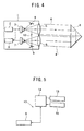
- In distance measurement based on a light wave, a modulated measuring light beam is used, and a distance is determined from a phase difference of the reflected light beam. Fig. 4 is a drawing to explain a basic type of a
distance measuring unit 1 of a distance measuring device, and Fig. 5 is a block diagram to explain thecontrol unit 13 of the distance measuring device. - When a distance measuring
light beam 4 is emitted from alight emitting element 3 which is modulated and driven by anoscillator 2, thedistance measuring light 4 is turned to a parallel beam by anobjective lens 5 and this beam is projected to areflection prism 6, which is an object to be measured. Thedistance measuring light 4 reflected by thereflection prism 6 enters theobjective lens 5 again and is received by aphotodetection element 7. A part of the distance measuring light beam emitted from thelight emitting element 3 is reflected by areflection mirror 9 and it is received by thephotodetection element 7 as an internalreference light beam 12. - Based on photodetection signals of the received distance measuring
light beam 4 and the received internalreference light beam 12, the distance is calculated from the phase difference by adistance measuring circuit 8. - The distance to the object to be measured (the reflection prism 6) as obtained by the
distance measuring circuit 8 is displayed on adisplay unit 15 as a numerical value indicating the distance based on the control by aCPU 14. Distance measuring instruction, data, etc. are inputted from akeyboard unit 16. - Fig. 6 is a drawing to explain the
distance measuring unit 1 more concretely. - On the side of the
light emitting element 3, achopper 17 is provided to cut off the distance measuringlight beam 4 coming from thelight emitting element 3 such as LED, LD, etc., and thechopper 17 is rotated by an opticalpath changing motor 18. On the side of thephotodetection element 7, adensity filter 20 is provided to filter a reflected distance measuring light 4', and thedensity filter 20 is rotated by adensity adjusting motor 21. As thephotodetection element 7, APD (avalanche photodiode) is used depending on the conditions such as photodetection sensitivity. - The
chopper 17 is provided with such a pattern that the light beam on the inner side and the light beam on the outer side are alternately cut off. When thechopper 17 is rotated by the opticalpath changing motor 18, the optical path is changed alternately. Thedensity filter 20 is provided with such a pattern that the density is gradually changed in rotating direction. When a rotating position of thedensity filter 20 is selected by thedensity adjusting motor 21, the received light amount of thephotodetection element 7 can be adjusted. The light amount of the reflected distance measuring light beam 4' entering thephotodetection element 7 is increased or decreased according to the distance between thereflection prism 6 and the distance measuring device. By properly selecting the position of thedensity filter 20, the received light amount of thephotodetection element 7 can be maintained on a constant level. - Based on the photodetection light amount (i.e. the received light amount) of the
photodetection element 7, thedensity adjusting motor 21 is rotated so that the light amount of the reflected distance measuring light beam 4' and the internalreference light beam 12 entering thephotodetection element 7 is maintained at a constant level, and the position of thedensity filter 20 is controlled. In synchronization with a reference signal issued by thedistance measuring circuit 8, the opticalpath changing motor 18 is rotated and controlled, and the reflected distance measuring light beam 4' and the internalreference light beam 12 entering thephotodetection element 7 are switched over. - The avalanche photodiode (APD) as described above has highly accurate photodetection sensitivity and has a wide dynamic range, and it is used as a photodetection element. However, the characteristics of APD widely vary according to each individual element, and adjustment is necessary when it is incorporated in a distance measuring device. In particular, the adjustment is indispensable in case of a distance measuring device with high accuracy.
- By changing a bias voltage, APD has an ability to adjust a magnification of an electric current by receiving the light beam. The characteristics of the bias voltage and the output current of APD are shown in Fig. 7. As shown in Fig. 7, APD has a wide range of the magnification, and it can be 150 times or more. When the bias voltage exceeds a certain level (Va), an avalanche phenomenon occurs. Therefore, in the adjustment of APD, the bias voltage is set to a value lower than the bias voltage to induce the avalanche while maintaining the needed magnification.
- Description will be given now on a conventional adjustment mode of APD.
- In the past, a special-purpose adjustment tool has been required for the adjustment.
- As shown in Fig. 8, a conventional type adjustment tool comprises a combination of an
LED 22 for adjustment and adensity filter 23. - First, a light beam is emitted from the
LED 22, of which output light amount is determined at a constant level, and it is projected toward thephotodetection element 7 at a predetermined position. The emitted light beam is modulated in the same manner as the actual distance measuringlight beam 4. - APD directly receives the light beam from the
LED 22, and the adjustment is made from a value obtained by photoelectric conversion. The magnification in this case is assumed as 1 x. - Next, a 1/150
density filter 23 is inserted between thephotodetection element 7 and theLED 22. The photodetection light amount of the APD is turned to 1/150 of the initial value. When the photodetection light amount is decreased to 1/150, the bias voltage is increased in such manner that the output current from APD is equalized to the value when thedensity filter 23 is not used. By the equalized bias voltage, the magnification of 150 times is obtained. - However, even with the
photodetection element 7 thus adjusted, it sometimes happens that the accurate output current as set to 150 times may not be obtained depending on the frequency of the use of the distance measuring device, the course over time, etc. In such case, the product must be adjusted again. For this reason, in the past, the distance measuring device has been re-adjusted periodically or after the use of a predetermined period of time. As described above, a special-purpose adjustment tool and a measuring instrument are required for the adjustment, and the user of the distance measuring device cannot perform adjustment as desired, and the re-adjustment has been usually requested to the manufacturer. This means that complicated procedures are required each time the distance measuring device has to be sent back to the manufacturer for re-adjustment. Also, the distance measuring device cannot be used during the re-adjustment, and this causes much inconvenience to the user. - It is an object of the present invention to provide a distance measuring device and a method for adjustment, by which it is possible to adjust the photodetection element (APD) in an easy and convenient manner, to eliminate complicated procedures for the re-adjustment, and to exclude the limitation on the use of the distance measuring device due to the re-adjustment.
- To attain the above object, the present invention provides a distance measuring device for measuring a distance, comprising a light emitting unit for emitting a measuring light beam toward an object to be measured, and a photodetection unit for receiving a reflected light beam reflected from the object to be measured, wherein the distance measuring device comprises a gain control unit for changing photodetection sensitivity of the photodetection unit by a bias voltage and a light amount switching unit for variably changing a light amount of the light emitting element which emits said light beam toward the photodetection unit. Further, the present invention provides a distance measuring device as described above, wherein the light emitting unit comprises a light source for emitting the measuring light beam and a light emitting element for adjustment for emitting a specifying light beam for adjustment, and the light amount switching unit can variably change a light amount of the light emitting element for adjustment. Also, the present invention provides a method for adjusting a photodetection unit of a distance measuring device which has a light emitting unit for projecting a measuring light beam toward an object to be measured, and a photodetection element for receiving a reflected measuring light beam reflected from the object to be measured, comprising the step of projecting a light beam from the light emitting element with a plurality of values of specifying light amount toward the photodetection element, and the step of determining a range of photodetection sensitivity of the photodetection element in response to a change of the light amount. Further, the present invention provides a method for adjusting a photodetection unit of a distance measuring device as described above, wherein the light emitting unit comprises a light source for emitting a measuring light beam and a light emitting element for adjustment for emitting a specifying light beam for adjustment, wherein a light amount of the light emitting element for adjustment can be variably changed. Also, the present invention provides a method for adjusting a photodetection unit of a distance measuring device as described above, wherein the light emitting unit attenuates light at a predetermined magnification to a specifying light amount, and a bias voltage is determined in such manner that sensitivity of a predetermined magnification of the photodetection element can be obtained according to a light attenuating condition. Further, the present invention provides a method for adjusting a photodetection unit of a distance measuring device as described above, wherein the light emitting unit sequentially emits the light beam of a specifying light amount in a plurality of stages, a bias voltage is sequentially changed in response to the light amount emitted by the light emitting unit, and the bias voltage of the photodetection element is determined when the light emitting unit finishes a light emission in a predetermined plurality of stages.
-
- Fig. 1 is a circuit diagram showing an essential portion of an embodiment of the present invention;
- Fig. 2 shows drawings to explain operation of an embodiment of the present invention;
- Fig. 3 shows drawings to explain operation of another embodiment of the present invention;
- Fig. 4 is a drawing schematically showing a distance measuring unit of a distance measuring device;
- Fig. 5 is a block diagram of the distance measuring unit;
- Fig. 6 is a drawing to explain the distance measuring unit of the distance measuring device;
- Fig. 7 is a diagram showing sensitivity characteristics of a photodetection element to be used in the distance measuring device; and
- Fig. 8 is a drawing to explain general feature of an adjustment tool of a conventional type light emitting element for adjustment.
-
- Description will be given below on embodiments of the present invention referring to the drawings.
- Fig. 1 is a block diagram showing a photodetection sensitivity adjusting unit of a distance measuring device. The photodetection sensitivity adjusting unit comprises a
gain control unit 24 and a lightamount switching unit 38. Thegain control unit 24 comprises acontrol unit 25, abias circuit 26 where an output of a bias voltage is controlled by thecontrol unit 25, aphotodetection element 7 on which the bias voltage is applied by thebias circuit 26, aresistance 27 for adjusting a branched current value from thephotodetection element 7, anamplifier 28 for amplifying the outputted branched current of thephotodetection element 7, a peak-hold circuit 29 for holding a peak value of an output value from theamplifier 28, and an A/D converter 31 for converting the output value from the peak-hold circuit 29 to a digital signal. - The light
amount switching unit 38 is connected to alight emitting element 32 for adjustment and thecontrol unit 25. Explanation will be given on the lightamount switching unit 38. Afirst switching transistor 33 and afirst resistance 34 are connected to thelight emitting element 32 for adjustment. Further, asecond switching transistor 35 and asecond resistance 36 are connected in parallel to thelight emitting element 32 for adjustment. A resistance value (10Ω in the figure) of thefirst resistance 34 is set to 1/10 of a resistance value (100Ω in the figure) of thesecond resistance 36. A switchingcircuit 37 for applying an ON/OFF control voltage is connected to thefirst switching transistor 33 and thesecond switching transistor 35, and the switchingcircuit 37 is controlled by thecontrol unit 25. - An adjustment specifying light beam to be emitted from the
light emitting element 32 for adjustment is designed to enter thephotodetection element 7, and it has an optical system for magnification adjustment which is different from a distance measuring optical system shown in Fig. 6. - Description will be given below on the operation referring to Fig. 2.
- A magnification of the
photodetection element 7 is adjusted after the distance measuring device has been used for a predetermined period of time or when a predetermined period of time has elapsed. - Light emission of the
light emitting element 3 is stopped, and a light beam is emitted from thelight emitting element 32 for adjustment. - First, the control voltage to the
second switching transistor 35 is turned off, and the control voltage is applied on thefirst switching transistor 33. An initial driving current determined by thefirst resistance 34 flows to the adjustmentlight emitting element 32, and the adjustmentlight emitting element 32 emits the light beam. The reference bias voltage is applied on thephotodetection element 7 by thebias circuit 26. Thebias circuit 26 outputs an electric current which is determined by the reference bias voltage and by the light amount from thelight emitting element 32 for adjustment. A reference peak value of the output current is detected by the peak-hold circuit 29 and the A/D converter 31, and this is inputted to thecontrol unit 25. Thecontrol unit 25 stores this reference peak value in memory. - Next, a light amount switching command signal is issued from the
control unit 25 to the switchingcircuit 37. The switchingcircuit 37 turns off the control voltage to thefirst switching transistor 33, and the control voltage is applied to thesecond switching transistor 35. A change driving current determined by thesecond resistance 36 flows to the adjustmentlight emitting element 32, and the light beam is emitted. The change driving current is 1/10 of the reference driving current, and the amount of the emitted light beam is attenuated to 1/10. - The output current value from the
photodetection element 7 under light attenuation is detected by the peak-hold circuit 29 and the A/D converter 31, and this is stored by thecontrol unit 25 as a smallest magnification peak value. - The
control unit 25 issues a bias voltage increase signal to thebias circuit 26, and thebias circuit 26 increases the bias voltage applied on thephotodetection element 7. The current value outputted by thephotodetection element 7 is feedbacked to thecontrol unit 25 from the peak-hold circuit 29 and the A/D converter 31, and thebias circuit 26 is controlled until the feedbacked output current reaches a value which is 15 times as high as the reference peak value. Thecontrol unit 25 stores the peak value at the moment when the output current of thephotodetection element 7 reaches avalue 15 times as high as the reference peak value as the highest magnification peak value, and the bias voltage at this moment is stored as the highest magnification bias voltage. - Under light attenuation of the adjustment
light emitting element 32, the ratio of the lowest magnification peak value and the highest magnification peak value of thephotodetection element 7 is 150 times. By changing the bias voltage from the reference bias voltage to the highest magnification bias voltage, the photodetection sensitivity of thephotodetection element 7 can be increased to 150 times. - The magnification to be set is not limited to 150 times. If the peak value at the moment when the output current of the
photodetection element 7 reaches avalue 10 times as high as the reference peak value is stored as the highest magnification peak value, and if the bias voltage at this moment is stored as the highest magnification bias voltage, the photodetection sensitivity will be 100 times. In the above embodiment, the switchingcircuit 37 is separately provided, while it may be designed in such manner that, the amount of the emitted light beam from thelight emitting element 3 may be changed by utilizing aninternal reference light 12 and a reflected distance measuring light 4' which are emitted from thelight emitting element 3. - Description will be given now on another embodiment referring to Fig. 3.
- For this embodiment, the details of a photodetection sensitivity adjusting unit are not specifically given here. The circuit configuration is similar to that of the above embodiment. Three or more switching elements are connected in parallel to the
light emitting element 32 for adjustment, and the light amount is switched by three steps or more by the switchingcircuit 37. In the following, description will be given referring to Fig. 1. - The light amount of the adjustment
light emitting element 32 is decreased stepwise by the lightamount switching unit 38. Thebias circuit 26 is controlled by thecontrol unit 25 in such manner that the output current of thephotodetection element 7 in each step serves as a reference value, and the bias voltage is increased stepwise. Finally, the magnification of 150 times is obtained. - The light beam of a predetermined light amount is emitted from the adjustment
light emitting element 32. The output of thephotodetection element 7 of the bias voltage in this case is assumed as a magnification of 1 x. The light amount is determined in advance from the characteristics of thephotodetection element 7 as specified by the manufacturer. The bias voltage at this moment is very low and it is nearly 0 V. The output current value of thephotodetection element 7 at this moment is sampled, and it is converted by A/D conversion. Then, a reference peak value is detected and it is stored by thecontrol unit 25. - Next, the light
amount switching unit 38 is controlled by thecontrol unit 25, and the light amount of the adjustmentlight emitting element 32 is decreased to the light amount of the next step. In this case, the peak value detected from the output current of thephotodetection element 7 is decreased in association with the light amount. To compensate this decrease, thebias circuit 26 is controlled in such manner that the peak value will be equalized with the reference peak value, and the bias voltage is decreased. - The light amount of the adjustment
light emitting element 32 is decreased and the bias voltage is increased so that the peak value is equalized with the reference peak value. This procedure is repeated, and the adjustment is completed when the magnification ultimately reaches the predetermined magnification value, i.e. 150 times. - In the above embodiment, the light amount is electrically switched, while the light amount may be optically switched using a density filter. It may be designed in such manner that a
reflection prism 6 is placed at a predetermined position with respect to the distance measuring device, and the light amount received by thephotodetection element 7 may be switched by utilizing the reflected distance measuring light 4' and thedensity filter 20. - The present invention provides a distance measuring device, which comprises a light emitting unit for emitting a distance measuring light beam to an object to be measured and a photodetection element for receiving a reflected measuring light beam reflected from the object to be measured. The light emitting unit can project the light beam of a plurality of values of specified light amount to the photodetection element, and a range of photodetection sensitivity of the photodetection element is determined in response to a change of the light amount. As a result, the sensitivity of the photodetection element (APD) can be adjusted without using a density filter. This makes it possible to design a system in a simple structure and to perform an adjustment in an easy manner. Also, it is possible to eliminate the complicated procedures for the re-adjustment and to exclude the limitation on the use of the distance measuring device for the purpose of the re-adjustment.
Claims (6)
- A distance measuring device for measuring a distance, comprising a light emitting unit for emitting a measuring light beam toward an object to be measured, and a photodetection unit for receiving a reflected measuring light beam reflected from said object to be measured, wherein said distance measuring device comprises a gain control unit for changing photodetection sensitivity of said photodetection unit by a bias voltage and a light amount switching unit for variably changing a light amount of said light emitting element which emits said light beam toward said photodetection unit.
- A distance measuring device according to claim 1, wherein said light emitting unit comprises a light source for emitting said measuring light beam and a light emitting element for adjustment for emitting a specifying light beam for adjustment, and said light amount switching unit can variably change a light amount of said light emitting element for adjustment.
- A method for adjusting a photodetection unit of a distance measuring device which has a light emitting unit for projecting a measuring light beam toward an object to be measured, and a photodetection element for receiving a reflected measuring light beam reflected from said object to be measured, comprising the step of projecting a light beam from said light emitting element with a plurality of values of specifying light amount toward said photodetection element, and the step of determining a range of photodetection sensitivity of said photodetection element in response to a change of the light amount.
- A method for adjusting a photodetection unit of a distance measuring device according to claim 3, wherein said light emitting unit comprises a light source for emitting a measuring light beam and a light emitting element for adjustment for emitting a specifying light beam for adjustment, wherein a light amount of said light emitting element for adjustment can be variably changed.
- A method for adjusting a photodetection unit of a distance measuring device according to claim 3, wherein said light emitting unit attenuates light at a predetermined magnification to a specifying light amount, and a bias voltage is determined in such manner that sensitivity of a predetermined magnification of said photodetection element can be obtained according to a light attenuating condition.
- A method for adjusting a photodetection unit of a distance measuring device according to claim 3, wherein said light emitting unit sequentially emits said light beam of a specifying light amount in a plurality of stages, a bias voltage is sequentially changed in response to said light amount emitted by said light emitting unit, and said bias voltage of said photodetection element is determined when said light emitting unit finishes a light emission in a predetermined plurality of stages.
Applications Claiming Priority (2)
| Application Number | Priority Date | Filing Date | Title |
|---|---|---|---|
| JP34726699A JP4630413B2 (en) | 1999-12-07 | 1999-12-07 | Distance measuring machine and light receiving unit adjusting method of distance measuring machine |
| JP34726699 | 1999-12-07 |
Publications (3)
| Publication Number | Publication Date |
|---|---|
| EP1106963A2 true EP1106963A2 (en) | 2001-06-13 |
| EP1106963A3 EP1106963A3 (en) | 2003-08-06 |
| EP1106963B1 EP1106963B1 (en) | 2014-07-02 |
Family
ID=18389062
Family Applications (1)
| Application Number | Title | Priority Date | Filing Date |
|---|---|---|---|
| EP00310876.8A Expired - Lifetime EP1106963B1 (en) | 1999-12-07 | 2000-12-07 | Distance measuring device and method for adjusting photodetection unit |
Country Status (3)
| Country | Link |
|---|---|
| US (1) | US6693703B2 (en) |
| EP (1) | EP1106963B1 (en) |
| JP (1) | JP4630413B2 (en) |
Families Citing this family (7)
| Publication number | Priority date | Publication date | Assignee | Title |
|---|---|---|---|---|
| US6762846B1 (en) | 2002-09-19 | 2004-07-13 | Nanometrics Incorporated | Substrate surface profile and stress measurement |
| US20050230605A1 (en) * | 2004-04-20 | 2005-10-20 | Hamid Pishdadian | Method of measuring using a binary optical sensor |
| JP4855749B2 (en) * | 2005-09-30 | 2012-01-18 | 株式会社トプコン | Distance measuring device |
| JP2008270558A (en) * | 2007-04-20 | 2008-11-06 | Sumitomo Electric Ind Ltd | Method for adjusting light receiving module |
| JP6045963B2 (en) * | 2013-04-05 | 2016-12-14 | 日立マクセル株式会社 | Optical distance measuring device |
| WO2021182224A1 (en) * | 2020-03-11 | 2021-09-16 | 株式会社デンソー | Measuring device |
| WO2022039871A1 (en) * | 2020-08-17 | 2022-02-24 | Beijing Voyager Technology Co. Ltd. | Dynamic receiver gain control for lidar system |
Citations (2)
| Publication number | Priority date | Publication date | Assignee | Title |
|---|---|---|---|---|
| US4464048A (en) | 1981-03-25 | 1984-08-07 | Barr & Stroud Limited | Laser rangefinders |
| JPH0854468A (en) | 1994-08-10 | 1996-02-27 | Nikon Corp | Photoreceiver |
Family Cites Families (9)
| Publication number | Priority date | Publication date | Assignee | Title |
|---|---|---|---|---|
| US3815994A (en) * | 1972-03-31 | 1974-06-11 | Kaman Sciences Corp | System and method for measuring distance |
| SE382507B (en) * | 1974-06-05 | 1976-02-02 | Aga Ab | WAY TO REGULATE THE GAIN IN A RADIATION DETECTIVE LOW INDIOD. |
| CH634419A5 (en) * | 1978-10-11 | 1983-01-31 | Kern & Co Ag | METHOD FOR ELECTROOPTIC DISTANCE MEASUREMENT AND DEVICE FOR IMPLEMENTING THE METHOD. |
| JPS60149929A (en) * | 1984-11-26 | 1985-08-07 | Tokyo Optical Co Ltd | Temperature compensator for avalanche diode |
| JPH0346588A (en) * | 1989-07-13 | 1991-02-27 | Mitsubishi Electric Corp | Laser receiver |
| US5396510A (en) * | 1993-09-30 | 1995-03-07 | Honeywell Inc. | Laser sensor capable of measuring distance, velocity, and acceleration |
| JP2951547B2 (en) * | 1994-10-03 | 1999-09-20 | 浜松ホトニクス株式会社 | Lightwave distance meter and distance measurement method |
| US5691808A (en) * | 1995-07-31 | 1997-11-25 | Hughes Electronics | Laser range finder receiver |
| DE19643287A1 (en) * | 1996-10-21 | 1998-04-23 | Leica Ag | Method and device for calibrating distance measuring devices |
-
1999
- 1999-12-07 JP JP34726699A patent/JP4630413B2/en not_active Expired - Fee Related
-
2000
- 2000-11-29 US US09/726,143 patent/US6693703B2/en not_active Expired - Lifetime
- 2000-12-07 EP EP00310876.8A patent/EP1106963B1/en not_active Expired - Lifetime
Patent Citations (2)
| Publication number | Priority date | Publication date | Assignee | Title |
|---|---|---|---|---|
| US4464048A (en) | 1981-03-25 | 1984-08-07 | Barr & Stroud Limited | Laser rangefinders |
| JPH0854468A (en) | 1994-08-10 | 1996-02-27 | Nikon Corp | Photoreceiver |
Also Published As
| Publication number | Publication date |
|---|---|
| US6693703B2 (en) | 2004-02-17 |
| EP1106963A3 (en) | 2003-08-06 |
| EP1106963B1 (en) | 2014-07-02 |
| JP2001165654A (en) | 2001-06-22 |
| US20010002860A1 (en) | 2001-06-07 |
| JP4630413B2 (en) | 2011-02-09 |
Similar Documents
| Publication | Publication Date | Title |
|---|---|---|
| JP4709931B2 (en) | Distance measuring device and distance measuring method | |
| KR100484345B1 (en) | Device for calibrating distance-measuring apparatus | |
| EP0905490A1 (en) | Optical component tester | |
| EP2437029A2 (en) | Distance Measuring Instrument | |
| JPH1123709A (en) | Distance-measuring device | |
| JP4761751B2 (en) | Distance measuring device | |
| CN112219135A (en) | Distance measuring device, distance measuring method and mobile platform | |
| US4488813A (en) | Reflectivity compensating system for fiber optic sensor employing dual probes at a fixed gap differential | |
| EP1106963A2 (en) | Distance measuring device and method for adjusting photodetection unit | |
| JP2006329797A (en) | Light wave range finder | |
| US10802221B1 (en) | Dynamically optimized tunable filters for optical sensing systems | |
| JPH0548849B2 (en) | ||
| JP2552325Y2 (en) | Lightwave ranging device | |
| KR20010044477A (en) | Apparatus and Method for mearsuring a distance using LASER | |
| JP4629823B2 (en) | Light wave rangefinder | |
| US7045772B2 (en) | Device and method for controlling the optical power in a microscope | |
| JP7332650B2 (en) | Optical spectrum analyzer and pulse modulated light measurement method | |
| JPH09281237A (en) | Laser distance measuring instrument | |
| JPH08240655A (en) | Method and device for processing signal | |
| JP2882813B2 (en) | Distance measuring device | |
| JP2006086431A (en) | Wavelength variable light source and wavelength characteristics measuring system | |
| JPH06258436A (en) | Electro-optical distance measuring equipment | |
| JP2002324909A (en) | Photoelectric conversion circuit and laser range finder | |
| JP3977511B2 (en) | Emitter / receiver | |
| JPH03160317A (en) | Laser light controlling device of measuring apparatus |
Legal Events
| Date | Code | Title | Description |
|---|---|---|---|
| PUAI | Public reference made under article 153(3) epc to a published international application that has entered the european phase |
Free format text: ORIGINAL CODE: 0009012 |
|
| AK | Designated contracting states |
Kind code of ref document: A2 Designated state(s): AT BE CH CY DE DK ES FI FR GB GR IE IT LI LU MC NL PT SE TR |
|
| AX | Request for extension of the european patent |
Free format text: AL;LT;LV;MK;RO;SI |
|
| PUAL | Search report despatched |
Free format text: ORIGINAL CODE: 0009013 |
|
| AK | Designated contracting states |
Designated state(s): AT BE CH CY DE DK ES FI FR GB GR IE IT LI LU MC NL PT SE TR |
|
| AX | Request for extension of the european patent |
Extension state: AL LT LV MK RO SI |
|
| RIC1 | Information provided on ipc code assigned before grant |
Ipc: 7G 01S 17/08 B Ipc: 7G 01S 7/48 B Ipc: 7G 01C 3/08 A |
|
| 17P | Request for examination filed |
Effective date: 20031125 |
|
| AKX | Designation fees paid |
Designated state(s): CH DE LI SE |
|
| 17Q | First examination report despatched |
Effective date: 20080624 |
|
| GRAP | Despatch of communication of intention to grant a patent |
Free format text: ORIGINAL CODE: EPIDOSNIGR1 |
|
| GRAJ | Information related to disapproval of communication of intention to grant by the applicant or resumption of examination proceedings by the epo deleted |
Free format text: ORIGINAL CODE: EPIDOSDIGR1 |
|
| INTG | Intention to grant announced |
Effective date: 20140108 |
|
| GRAP | Despatch of communication of intention to grant a patent |
Free format text: ORIGINAL CODE: EPIDOSNIGR1 |
|
| INTG | Intention to grant announced |
Effective date: 20140129 |
|
| GRAS | Grant fee paid |
Free format text: ORIGINAL CODE: EPIDOSNIGR3 |
|
| GRAA | (expected) grant |
Free format text: ORIGINAL CODE: 0009210 |
|
| AK | Designated contracting states |
Kind code of ref document: B1 Designated state(s): CH DE LI SE |
|
| REG | Reference to a national code |
Ref country code: CH Ref legal event code: EP Ref country code: CH Ref legal event code: NV Representative=s name: FIAMMENGHI-FIAMMENGHI, CH |
|
| REG | Reference to a national code |
Ref country code: DE Ref legal event code: R096 Ref document number: 60048638 Country of ref document: DE Effective date: 20140814 |
|
| REG | Reference to a national code |
Ref country code: SE Ref legal event code: TRGR |
|
| REG | Reference to a national code |
Ref country code: DE Ref legal event code: R097 Ref document number: 60048638 Country of ref document: DE |
|
| PLBE | No opposition filed within time limit |
Free format text: ORIGINAL CODE: 0009261 |
|
| STAA | Information on the status of an ep patent application or granted ep patent |
Free format text: STATUS: NO OPPOSITION FILED WITHIN TIME LIMIT |
|
| 26N | No opposition filed |
Effective date: 20150407 |
|
| PGFP | Annual fee paid to national office [announced via postgrant information from national office to epo] |
Ref country code: SE Payment date: 20151211 Year of fee payment: 16 |
|
| REG | Reference to a national code |
Ref country code: SE Ref legal event code: EUG |
|
| PG25 | Lapsed in a contracting state [announced via postgrant information from national office to epo] |
Ref country code: SE Free format text: LAPSE BECAUSE OF NON-PAYMENT OF DUE FEES Effective date: 20161208 |
|
| PGFP | Annual fee paid to national office [announced via postgrant information from national office to epo] |
Ref country code: DE Payment date: 20171129 Year of fee payment: 18 |
|
| PGFP | Annual fee paid to national office [announced via postgrant information from national office to epo] |
Ref country code: CH Payment date: 20171212 Year of fee payment: 18 |
|
| REG | Reference to a national code |
Ref country code: DE Ref legal event code: R119 Ref document number: 60048638 Country of ref document: DE |
|
| REG | Reference to a national code |
Ref country code: CH Ref legal event code: PL |
|
| PG25 | Lapsed in a contracting state [announced via postgrant information from national office to epo] |
Ref country code: DE Free format text: LAPSE BECAUSE OF NON-PAYMENT OF DUE FEES Effective date: 20190702 |
|
| PG25 | Lapsed in a contracting state [announced via postgrant information from national office to epo] |
Ref country code: LI Free format text: LAPSE BECAUSE OF NON-PAYMENT OF DUE FEES Effective date: 20181231 Ref country code: CH Free format text: LAPSE BECAUSE OF NON-PAYMENT OF DUE FEES Effective date: 20181231 |