EP1107395A2 - Lamp socket - Google Patents
Lamp socket Download PDFInfo
- Publication number
- EP1107395A2 EP1107395A2 EP00125664A EP00125664A EP1107395A2 EP 1107395 A2 EP1107395 A2 EP 1107395A2 EP 00125664 A EP00125664 A EP 00125664A EP 00125664 A EP00125664 A EP 00125664A EP 1107395 A2 EP1107395 A2 EP 1107395A2
- Authority
- EP
- European Patent Office
- Prior art keywords
- leg
- socket
- abutment
- detent spring
- holding
- Prior art date
- Legal status (The legal status is an assumption and is not a legal conclusion. Google has not performed a legal analysis and makes no representation as to the accuracy of the status listed.)
- Granted
Links
Images


Classifications
-
- H—ELECTRICITY
- H01—ELECTRIC ELEMENTS
- H01R—ELECTRICALLY-CONDUCTIVE CONNECTIONS; STRUCTURAL ASSOCIATIONS OF A PLURALITY OF MUTUALLY-INSULATED ELECTRICAL CONNECTING ELEMENTS; COUPLING DEVICES; CURRENT COLLECTORS
- H01R33/00—Coupling devices specially adapted for supporting apparatus and having one part acting as a holder providing support and electrical connection via a counterpart which is structurally associated with the apparatus, e.g. lamp holders; Separate parts thereof
- H01R33/05—Two-pole devices
- H01R33/06—Two-pole devices with two current-carrying pins, blades or analogous contacts, having their axes parallel to each other
- H01R33/08—Two-pole devices with two current-carrying pins, blades or analogous contacts, having their axes parallel to each other for supporting tubular fluorescent lamp
- H01R33/0836—Two-pole devices with two current-carrying pins, blades or analogous contacts, having their axes parallel to each other for supporting tubular fluorescent lamp characterised by the lamp holding means
Definitions
- the invention relates to a socket for lamps according to the Preamble of claim 1.
- the The present invention is based on the holding leg of the Latching spring following one in the depth of the socket bend of about 180 ° to be accommodated on the abutment legs, from which the tongue is cut out as a U-shaped tongue is formed.
- the detent spring is in the lamp insertion direction with its U-shaped Bend ahead in a pocket-like recess in the Socket housing inserted until it hits a stop. In This position can be shown on the outside of the abutment leg Locking tongue behind a retaining surface of the socket housing snap, so that the detent spring against a tensile force on the lamp holds securely in the socket housing.
- the free end of the abutment section is supported in this final assembly position by an inward facing one Area within the socket housing.
- the bent shoulder of the holding leg protrudes into the Path of movement of the lamp base or to attack the shoulder mating surface provided on it.
- the present invention has for its object, means and Show ways like a version with at least one Latching spring in the sense of a significant reduction in the material requirement is still to be optimized for the detent spring.
- the invention solves this problem with the features of Claim 1 and is particularly characterized in that the Abutment leg formed from the holding leg and itself is also a latch.
- the essential essence of the invention is therefore that additional, i.e. provided in the extension of the holding leg, To completely leave out abutment legs. According to the invention this happens because the abutment leg and its function from the extended and bent end portion of the detent spring in the area that was previously only relocated from the holding leg was taken. This will result in enormous material savings achieved because - assuming comparable dimensions of the end product - over a third of the length of the metal strip from which the detent spring is produced, is no longer needed.
- the Abutment leg cut out of the flat sheet metal strip and is issued in such a way that its free end corresponds to the end of the Holding leg points on which the bent shoulder is located.
- the arrangement in the prior art is as follows hit that in an end region of the flat holding leg a leg was also cut out in a U shape. However, this was not the abutment leg itself, but one that is detached from it and exhibited special latch. Their free end points to immediately adjacent free end of the metal strip, but not to the free end of the not yet deformed holding leg, which is in the opposite Direction lies.
- the success of the invention is also based on the knowledge that the U-shaped incision in particular Sheet metal strip from which the detent spring is to be made, in a different way than to be ordered so far.
- the abutment leg preferably forms an oblique shape the straight section uplifting transition section into a extending substantially along the straight section End section merges.
- This end section serves to deal with its To support the outer surface on an inner surface of the socket housing, whereas its marginal edge delimits the inner surface Grips behind the lead.
- the abutment leg, starting from the zone of its Connection to the holding leg is essentially straight, that is, without Let the transition section run.
- the invention provides that one over the Connection zone of the transition section on the straight section of the Abutment leg protruding insertion section into one Receiving slot of the socket housing engages.
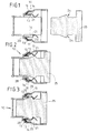
- the invention is most easily understood on the basis of the in 9 to 12 shown prior art.
- FIG. 9 10 denotes a lamp socket overall, whose socket housing 11 made of insulating material to each other diametrically opposite sides towards the lamp, not shown has open pockets 12 for a detent spring 13 each.
- Each Latch spring 13 is divided into a holding leg 14 and one a bend designated 15, about 180 ° subsequent abutment leg 16.
- This abutment leg 16 is supported with an outer surface 16a near its free end 16b from an inner surface 11a of the socket housing 11.
- a U-shaped incision 17 Fig. 12
- a barb and tongue-like latch 18 18
- the holding leg 14 of the detent spring 13 each has one bent shoulder 21 to attack an appropriate Counter surface of the base 25, not shown in FIGS. 9 to 12 Lamp serves.
- the holding leg 14 can, for example, be located at 15 Bend the bending axis in the direction of arrow 22 resiliently if a Lamp base 25 (Fig. 1 to 3) is inserted into the lamp holder 10. In the final operating position, the shoulders 21 snap towards one another Arrow direction 22 back into the lamp base 25 holding Operating position.
- the detent spring 13 after the State of the art has several functional elements, namely that for resilient latching attack on the lamp base 25 specific holding leg 14 with shoulder 21, one that is supported on the inside in the socket Abutment leg 16, namely following one end of the holding leg 14 attached U-shaped bend 15 and finally as a further and last functional element the tongue-like from the Abutment leg 16 notched latch 18.
- a detent spring 13 of this known type is a flat sheet metal strip 23 of length L (Fig. 12). It should be emphasized that the free edge 18a of the latch 18 from the free end 23a of the blank 23 points away, the free end 14a of the finished detent spring 13 Holding leg 14 forms. Rather, the edge 18a faces directly adjacent cutting edge 23b, which in the finished detent spring 13 free end of the abutment leg 16 forms.
- the version 10 shown in FIGS. 1 to 3 corresponding to the The invention has detent springs 13, the holding legs 14 of which are in turn one bent shoulder 21 for attacking counter surfaces 24 a Provide lamp base 25.
- the peculiarity is that the abutment leg 16 is integrated in the holding leg 14 and itself is also a latch.
- the tongue 26 is deformed such that a transition section 27 protrudes obliquely from the rectilinear portion of the retaining spring 14 and a free end portion by means of abutment legs 16 essentially to the free end 14a of the holding leg 14 or along this is turned continuously.
- This configuration is particularly from the 4 to 7 can be seen very clearly.
- socket housing 11 In the socket housing 11 are slit-like to the lamp base 25 open slot receptacles 28 are provided, in which the end portions 14b the holding leg 14 are inserted with their end face first. Not groove-like guides are shown in the socket housing 11 for guidance and holding lateral edge regions 14c of the holding legs 14.
Abstract
Description
Die Erfindung betrifft eine Fassung für Lampen nach dem Oberbegriff des Anspruchs 1.The invention relates to a socket for lamps according to the Preamble of claim 1.
Fassungen dieser Art dienen einerseits dazu, die elektrische Verbindung der Netzleitungen mit der Lampe herzustellen und zum anderen dazu, die Lampe mechanisch sicher zu halten. Unter diesem Aspekt ist es insbesondere bei Lampen mit Sockeln der im Oberbegriff genannten Typen bekannt, im Fassungsgehäuse wenigstens eine Rastfeder anzuordnen, die die Aufgabe hat, den Lampensockel in seiner in die Fassung eingesteckten Position zu halten bzw. diese Position gegen Herausfallen zu sichern.Versions of this type are used on the one hand, the electrical Connect the power lines to the lamp and to others to keep the lamp mechanically secure. Under this Aspect is particularly in the case of lamps with bases in the preamble known types known, at least one in the socket housing Arrange detent spring, which has the task of the lamp base in its hold in the inserted position or this position against Secure falling out.
Bei einer bekannten Fassung der vorausgesetzten Art, von der die vorliegende Erfindung ausgeht, schließt sich an den Halteschenkel der Rastfeder im Anschluß an eine in der Tiefe der Fassung unterzubringenden Umbiegung von etwa 180° der Widerlagerschenkel an, aus welchem als U-förmig ausgeschnittene Zunge die Rastnase ausgeformt ist. Die Rastfeder wird in Lampeneinsteckrichtung mit ihrer U-förmigen Umbiegung voran in eine taschenartige Ausnehmung im Fassungsgehäuse eingesteckt, bis sie gegen einen Anschlag trifft. In dieser Position kann die nach außen am Widerlagerschenkel ausgestellte Rastzunge hinter eine Rückhaltefläche des Fassungsgehäuses schnappen, so dass die Rastfeder entgegen einer Zugkraft an der Lampe sicher im Fassungsgehäuse hält. Das freie Ende des Widerlagerabschnitts stützt sich in dieser Endmontagelage an einer nach innen weisenden Fläche innerhalb des Fassungsgehäuses ab. Zum Zentrum der Fassung hin ragt die ausgebogene Schulter des Halteschenkels in die Bewegungsbahn des Lampensockels bzw. der zum Angriff der Schulter daran vorgesehenen Gegenfläche. Beim Einsetzen des Lampensockels drückt dieser den federnden Halteschenkel zunächst zur Seite, bis er in der voll einsteckten Position des Lampensockels hinter eine die Gegenfläche tragende Anschlagschulter des Lampensockels greifen kann.In a known version of the required type, of which the The present invention is based on the holding leg of the Latching spring following one in the depth of the socket bend of about 180 ° to be accommodated on the abutment legs, from which the tongue is cut out as a U-shaped tongue is formed. The detent spring is in the lamp insertion direction with its U-shaped Bend ahead in a pocket-like recess in the Socket housing inserted until it hits a stop. In This position can be shown on the outside of the abutment leg Locking tongue behind a retaining surface of the socket housing snap, so that the detent spring against a tensile force on the lamp holds securely in the socket housing. The free end of the abutment section is supported in this final assembly position by an inward facing one Area within the socket housing. To the center of the frame the bent shoulder of the holding leg protrudes into the Path of movement of the lamp base or to attack the shoulder mating surface provided on it. When inserting the lamp base This first pushes the resilient holding leg to the side until it is in the fully inserted position of the lamp base behind one Counter-bearing shoulder of the lamp base can grip.
Üblicherweise sind in einem Fassungsgehäuse in einander gegenüberliegender Anordnung zwei derartige Rastfedern angeordnet. Es gibt jedoch auch Ausführungen, bei denen nur einseitig eine solche Rastfeder vorgesehen ist, wohingegen auf der anderen Seite ein fassungsfester Anschlag vorgesehen ist.Usually are in a socket housing in each other opposite arrangement two such detent springs arranged. It However, there are also versions in which there is only one Detent spring is provided, whereas on the other side fixed stop is provided.
Fassungen der genannten Art haben sich insbesondere auch hinsichtlich der sicheren Halterung von Lampensockeln in der Praxis bewährt.Versions of the type mentioned have in particular with regard to the secure mounting of lamp bases in practice proven.
Der vorliegenden Erfindung liegt die Aufgabe zugrunde, Mittel und Wege aufzuzeigen, wie eine Fassung mit wenigstens einer solchen Rastfeder im Sinne einer deutlichen Verminderung des Werkstoffbedarfs für die Rastfeder noch zu optimieren ist.The present invention has for its object, means and Show ways like a version with at least one Latching spring in the sense of a significant reduction in the material requirement is still to be optimized for the detent spring.
Die Erfindung löst diese Aufgabe mit den Merkmalen des Anspruches 1 und ist insbesondere dadurch gekennzeichnet, dass der Widerlagerschenkel aus dem Halteschenkel ausgeformt und selbst zugleich auch Rastnase ist.The invention solves this problem with the features of Claim 1 and is particularly characterized in that the Abutment leg formed from the holding leg and itself is also a latch.
Der wesentliche Kern der Erfindung besteht mithin darin, den zusätzlichen, d.h. in Verlängerung des Halteschenkels vorgesehenen, Widerlagerschenkel gänzlich auszusparen. Entsprechend der Erfindung geschieht dies dadurch, dass der Widerlagerschenkel und seine Funktion von dem verlängerten und umgebogenen Endabschnitt der Rastfeder in denjenigen Bereich verlagert ist, der bisher lediglich vom Halteschenkel eingenommen wurde. Damit wird eine enorme Werkstoffeinsparung erzielt, weil - vergleichbare Dimensionen des Endprodukts vorausgesetzt - über ein Drittel der Länge des Blechstreifens, aus dem die Rastfeder hergestellt wird, nicht mehr benötigt wird. The essential essence of the invention is therefore that additional, i.e. provided in the extension of the holding leg, To completely leave out abutment legs. According to the invention this happens because the abutment leg and its function from the extended and bent end portion of the detent spring in the area that was previously only relocated from the holding leg was taken. This will result in enormous material savings achieved because - assuming comparable dimensions of the end product - over a third of the length of the metal strip from which the detent spring is produced, is no longer needed.
In geschickter praktischer Ausführung ist vorgesehen, dass der Widerlagerschenkel aus dem ebenen Blechstreifen freigeschnitten und derart ausgestellt ist, dass sein freies Ende zu dem Ende des Halteschenkels weist, an dem sich die ausgebogene Schulter befindet. Beim Stand der Technik ist im Unterschied dazu die Anordnung so getroffen, dass in einem Endbereich des ebenen Halteschenkels zwar ebenfalls in U-Form ein Schenkel ausgeschnitten war. Dies war allerdings nicht der Widerlagerschenkel selbst, sondern eine aus ihm ausgeklinkte und ausgestellte besondere Rastnase. Deren freies Ende weist zum unmittelbar benachbarten freien Ende des Blechstreifens, nicht jedoch zum freien Ende des noch nicht verformten Halteschenkels, der in entgegengesetzter Richtung liegt. Der Erfolg der Erfindung beruht also auch auf der Erkenntnis, den insbesondere U-förmigen Einschnitt im Blechstreifen, aus dem die Rastfeder herzustellen ist, in anderer Weise als bisher anzuordnen.In a clever, practical design, it is provided that the Abutment leg cut out of the flat sheet metal strip and is issued in such a way that its free end corresponds to the end of the Holding leg points on which the bent shoulder is located. In contrast, the arrangement in the prior art is as follows hit that in an end region of the flat holding leg a leg was also cut out in a U shape. However, this was not the abutment leg itself, but one that is detached from it and exhibited special latch. Their free end points to immediately adjacent free end of the metal strip, but not to the free end of the not yet deformed holding leg, which is in the opposite Direction lies. The success of the invention is also based on the knowledge that the U-shaped incision in particular Sheet metal strip from which the detent spring is to be made, in a different way than to be ordered so far.
Die Rastfeder weist entsprechend einer weiteren Ausgestaltung der Erfindung einen im wesentlichen geraden Abschnitt auf, aus dem der Widerlagerschenkel ausgeschnitten ist und an den sich zum einen Ende hin die ausgebogene Schulter anschließt.According to a further embodiment of the detent spring Invention on a substantially straight section from which the Abutment leg is cut out and to the one end towards the bent shoulder.
Vorzugsweise bildet der Widerlagerschenkel einen sich schräg aus dem geraden Abschnitt erhebenden Übergangsabschnitt aus, der in einen sich im wesentlichen entlang dem geraden Abschnitt erstreckenden Endabschnitt übergeht. Dieser Endabschnitt dient dazu, sich mit seiner Außenfläche an einer Innenfläche des Fassungsgehäuses abzustützen, wohingegen seine Randkante einen die Innenfläche begrenzenden Vorsprung hintergreift. Dies ist eine besonders zuverlässige Form und Ausgestaltung des Widerlagerschenkels, der zugleich die Widerlagerfunktion und die Funktion der Rastnase übernimmt, obgleich er ein und dasselbe Stück der Rastfeder ist. Alternativ ist es aber auch möglich, den Widerlagerschenkel, ausgehend von der Zone seiner Anbindung an dem Halteschenkel im wesentlichen geradlinig, also ohne Übergangsabschnitt verlaufen zu lassen.The abutment leg preferably forms an oblique shape the straight section uplifting transition section into a extending substantially along the straight section End section merges. This end section serves to deal with its To support the outer surface on an inner surface of the socket housing, whereas its marginal edge delimits the inner surface Grips behind the lead. This is a particularly reliable form and Design of the abutment leg, which is also the Abutment function and the function of the detent takes over, although he is one and the same piece of the detent spring. Alternatively, it is possible the abutment leg, starting from the zone of its Connection to the holding leg is essentially straight, that is, without Let the transition section run.
Schließlich sieht die Erfindung vor, dass ein über die Anbindungszone des Übergangsabschnitts am geraden Abschnitt des Widerlagerschenkels hinausragender Einsteckabschnitt in einen Aufnahmeschlitz des Fassungsgehäuses eingreift.Finally, the invention provides that one over the Connection zone of the transition section on the straight section of the Abutment leg protruding insertion section into one Receiving slot of the socket housing engages.
Im übrigen versteht sich die Erfindung am besten anhand der nachfolgenden Beschreibung einerseits des in Bezug genommenen Standes der Technik und andererseits eines bevorzugten Ausführungsbeispiels der Erfindung. In den Zeichnungen zeigen:
- Fig. 1
- einen Längsschnitt durch eine Lampenfassung mit davor schematisch dargestelltem Sockel einer nicht gezeigten Lampe vor dem Einstecken des Sockels in die Fassung,
- Fig. 2
- eine der Fig. 1 entsprechende Darstellung während des Einsteckens des Lampensockels in die Fassung,
- Fig. 3
- eine den Fig. 1 und 2 entsprechende Darstellung mit in Betriebsposition eingestecktem und in der Fassung festgehaltenem Lampensockel,
- Fig. 4
- eine gegenüber den Fig. 1 bis 3 vergrößert dargestellte Seitenansicht der Rastfeder,
- Fig. 5
- eine Stirnansicht der Rastfeder entsprechend dem Ansichtspfeil V in Fig. 4,
- Fig. 6
- eine Seitenansicht der Rastfeder nach Fig. 5 entsprechend dem Ansichtspfeil VI in Fig. 4,
- Fig. 7
- eine perspektivische Ansicht der Rastfeder entsprechend den Fig. 4 bis 6,
- Fig. 8
- eine Aufsicht auf den zur Herstellung der Rastfeder benötigten Blechstreifen nach dem Einschneiden des Bereichs für den Widerlagerschenkel, jedoch vor der Verformung,
- Fig. 9
- eine Fig. 1 entsprechende Schnittdarstellung einer herkömmlichen Lampenfassung,
- Fig. 10
- eine Fig. 4 entsprechende Seitenansicht der bekannten Rastfeder,
- Fig. 11
- eine Fig. 7 entsprechende perspektivische Ansicht der bekannten Rastfeder und
- Fig. 12
- eine maßstabsgetreu wiedergegebene Aufsicht entsprechend Fig. 8 auf einen Blechzuschnitt zur Herstellung der vorbekannten Rastfeder.
- Fig. 1
- 2 shows a longitudinal section through a lamp holder with a base of a lamp, not shown, shown schematically in front of it, before the base is inserted into the holder,
- Fig. 2
- 1 corresponding representation of the insertion of the lamp base into the socket,
- Fig. 3
- 1 and 2 corresponding representation with the lamp base inserted in the operating position and held in the socket,
- Fig. 4
- 1 to 3 enlarged side view of the detent spring,
- Fig. 5
- 3 shows an end view of the detent spring in accordance with the arrow V in FIG. 4,
- Fig. 6
- 5 according to the view arrow VI in Fig. 4,
- Fig. 7
- a perspective view of the detent spring corresponding to FIGS. 4 to 6,
- Fig. 8
- a view of the sheet metal strip required for producing the detent spring after the area for the abutment leg has been cut, but before the deformation,
- Fig. 9
- 1 corresponding sectional view of a conventional lamp holder,
- Fig. 10
- 4 corresponding side view of the known detent spring,
- Fig. 11
- a Fig. 7 corresponding perspective view of the known detent spring and
- Fig. 12
- 8 shows a scale representation corresponding to FIG. 8 of a sheet metal blank for the production of the known detent spring.
Am leichtesten versteht sich die Erfindung auf der Grundlage des in den Fig. 9 bis 12 dargestellten Standes der Technik.The invention is most easily understood on the basis of the in 9 to 12 shown prior art.
Dort ist in Fig. 9 mit 10 eine Lampenfassung insgesamt bezeichnet,
deren aus Isolierstoff bestehendes Fassungsgehäuse 11 an einander
diametral gegenüberliegenden Seiten zur nicht dargestellten Lampe hin
offene Einstecktaschen 12 für jeweils eine Rastfeder 13 aufweist. Jede
Rastfeder 13 gliedert sich in einen Halteschenkel 14 und einen sich an
eine mit 15 bezeichnete, etwa 180° betragende Umbiegung
anschließenden Widerlagerschenkel 16. Dieser Widerlagerschenkel 16
stützt sich mit einer Außenfläche 16a nahe seinem freien Ende 16b an
einer Innenfläche 11a des Fassungsgehäuses 11 ab. Weiterhin ist,
seinem freien Ende benachbart, mittels eines U-förmigen Einschnitts 17
(Fig. 12) eine widerhaken- sowie zungenartige Rastnase 18 ausgestellt.
Sie greift in der Betriebslage der Rastfeder 13 in einen
Fassungskörperausschnitt 19 ein, so dass ihr freies Ende 18a gegen eine
Rückhaltefläche 20 des Fassungsgehäuses 11 gerichtet ist. Dadurch ist
es unmöglich, die Rastfeder 13 nach dem Einsetzen in das
Fassungsgehäuse 11 unbeabsichtigt aus ihrer darin gesicherten Position
herauszuziehen.There, in FIG. 9, 10 denotes a lamp socket overall,
whose
Der Halteschenkel 14 der Rastfeder 13 besitzt jeweils eine
ausgebogene Schulter 21, die zum Angriff an einer entsprechenden
Gegenfläche des in den Fig. 9 bis 12 nicht dargestellten Sockels 25 einer
Lampe dient. Der Halteschenkel 14 kann, etwa mit bei 15 gelegener
Biegeachse in Pfeilrichtung 22 federnd nachgeben, wenn ein
Lampensockel 25 (Fig. 1 bis 3) in die Lampenfassung 10 eingesteckt wird.
In der endgültigen Betriebslage schnappen die Schultern 21 entgegen
Pfeilrichtung 22 zurück in die den Lampensockel 25 halternde
Betriebsposition.The holding
Aus Vorstehendem wird deutlich, dass die Rastfeder 13 nach dem
Stand der Technik mehrere Funktionselemente aufweist, nämlich den zum
federnden Rastangriff am Lampensockel 25 bestimmten Halteschenkel 14
mit Schulter 21, einen sich innen in der Fassung abstützenden
Widerlagerschenkel 16, und zwar im Anschluß an eine endseits des Halteschenkels
14 angebrachte U-förmige Umbiegung 15 sowie schließlich
als weiteres und letztes Funktionselement die zungenartig aus dem
Widerlagerschenkel 16 ausgeklinkte Rastnase 18.From the above it is clear that the
Ausgangsbasis für eine Rastfeder 13 dieser bekannten Art ist ein
ebener Blechstreifen 23 der Länge L (Fig. 12). Hervorzuheben ist, dass
die freie Kante 18a der Rastnase 18 vom freien Ende 23a des Zuschnitts
23 wegweist, der bei der fertigen Rastfeder 13 das freie Ende 14a des
Halteschenkels 14 bildet. Die Kante 18a weist vielmehr zur unmittelbar
benachbarten Zuschnittskante 23b, die bei der fertigen Rastfeder 13 das
freie Ende des Widerlagerschenkels 16 bildet.Starting basis for a
Die in den Fig. 1 bis 3 dargestellte Fassung 10 entsprechend der
Erfindung weist Rastfedern 13 auf, deren Halteschenkel 14 wiederum eine
ausgebogene Schulter 21 zum Angriff an Gegenflächen 24 eines
Lampensockels 25 bereitstellen. Die Besonderheit aber besteht darin,
dass der Widerlagerschenkel 16 in den Halteschenkel 14 integriert ist und
selbst auch Rastnase ist.The
Am besten zeigen die Fig. 5 bis 8 die Gestaltung dieser Rastfeder
13. Die Besonderheit besteht darin, dass aus dem relativ kurzen,
geradlinigen Abschnitt der Haltefeder 14 eine längliche Federzunge 26 mit
einem U-förmigen Schnitt 17 freigeschnitten ist, deren Anbindungsbereich
26a nahe dem der Schulter 21 abgewandten Ende 14b des Halteschenkels
14 angeordnet ist. Entsprechend weist das freie Ende 26b der
Zunge 26 beim noch nicht verformten Blechstreifen nach Fig. 8 zur
entfernteren Schmalkante 14a des Blechzuschnitts 23, wobei die Kante
14a dem freien Ende des Halteschenkels 14 jenseits der Schulter 21
entspricht.5 to 8 best show the design of this
Die Zunge 26 wird so verformt, dass ein Übergangsabschnitt 27
schräg von dem geradlinigen Abschnitt der Haltefeder 14 wegsteht und
ein freier Endabschnitt mittels Widerlagerschenkel 16 im wesentlichen
zum freien Ende 14a des Halteschenkels 14 bzw. längs zu diesem
verlaufend abgebogen wird. Diese Konfiguration ist insbesondere aus den
Fig. 4 bis 7 sehr deutlich ersichtlich. Diese zeigen auch, wie geschickt es
erfindungsgemäß gelungen ist, den Widerlagerschenkel 16 in den
Halteschenkel 14 zu integrieren. Die Rastfeder 13 entsprechend der
Erfindung kennt keine Umbiegung 15 und keinen sich daran
anschließenden verlängerten Widerlagerabschnitt 16. Ausgangsbasis für
die Rastfeder 13 ist der ebene Blechzuschnitt 23 entsprechend Fig. 8 mit
einer Länge I, die erheblich geringer und nur etwas länger als die Hälfte
der Länge L des bekannten Zuschnitts 23 nach Fig. 12 ist.The
Aufgrund der anhand der Fig. 4 bis 7 beschriebenen Bauform und
räumlichen Gestaltung der Rastfeder 13 versteht sich nunmehr unter
Bezugnahme auf die Fig. 1 bis 3 deren Anordnung in der Fassung 10
ohne weiteres.Due to the design described with reference to FIGS. 4 to 7 and
spatial design of the
Im Fassungsgehäuse 11 sind schlitzartige, zum Lampensockel 25
hin offene Schlitzaufnahmen 28 vorgesehen, in die die Endabschnitte 14b
der Halteschenkel 14 mit ihrer Stirnseite voran eingesteckt werden. Nicht
gezeigt sind nutartige Führungen im Fassungsgehäuse 11 zur Führung
und Halterung seitlicher Randbereiche 14c der Halteschenkel 14.In the
Ferner sind an der Innenseite des Fassungsgehäuses 14 kleine
Rastleisten 29 vorgesehen, hinter die nach dem Einstecken in der
Betriebsposition die Widerlagerschenkel 26 einschnappen können. Die
freien Kanten 16b der Widerlagerschenkel 16 übernehmen somit im
Zusammenwirken mit den Leisten 29 die Funktion der bisher gesondert
ausgeformten Rastnasen 18.Furthermore, 14 are small on the inside of the socket housing
Locking strips 29 are provided, behind which after insertion in the
Operating position can snap the
Claims (7)
Applications Claiming Priority (2)
| Application Number | Priority Date | Filing Date | Title |
|---|---|---|---|
| DE19958841 | 1999-12-07 | ||
| DE19958841A DE19958841A1 (en) | 1999-12-07 | 1999-12-07 | Lamp holder |
Publications (3)
| Publication Number | Publication Date |
|---|---|
| EP1107395A2 true EP1107395A2 (en) | 2001-06-13 |
| EP1107395A3 EP1107395A3 (en) | 2002-05-15 |
| EP1107395B1 EP1107395B1 (en) | 2003-07-23 |
Family
ID=7931648
Family Applications (1)
| Application Number | Title | Priority Date | Filing Date |
|---|---|---|---|
| EP00125664A Expired - Lifetime EP1107395B1 (en) | 1999-12-07 | 2000-11-23 | Lamp socket |
Country Status (5)
| Country | Link |
|---|---|
| US (1) | US6340310B2 (en) |
| EP (1) | EP1107395B1 (en) |
| AT (1) | ATE245859T1 (en) |
| DE (2) | DE19958841A1 (en) |
| ES (1) | ES2201991T3 (en) |
Cited By (1)
| Publication number | Priority date | Publication date | Assignee | Title |
|---|---|---|---|---|
| WO2012052869A1 (en) * | 2010-10-18 | 2012-04-26 | Koninklijke Philips Electronics N.V. | Lamp socket |
Families Citing this family (22)
| Publication number | Priority date | Publication date | Assignee | Title |
|---|---|---|---|---|
| US6755552B2 (en) * | 2002-04-23 | 2004-06-29 | Hung-Wen Lee | Conductive plate of a bulb assembly |
| US7033065B2 (en) * | 2003-08-06 | 2006-04-25 | The Coleman Company, Inc. | Lamp retainer assembly |
| DE202004007300U1 (en) * | 2004-05-07 | 2004-10-14 | Harting Electric Gmbh & Co. Kg | Device for fastening a connector |
| US7223011B2 (en) * | 2004-11-22 | 2007-05-29 | Otis Wright | Device for removing and installing fluorescent lights |
| DE102004062414A1 (en) * | 2004-12-20 | 2006-06-29 | Bjb Gmbh & Co.Kg | lamp socket |
| US7569981B1 (en) * | 2005-02-22 | 2009-08-04 | Light Sources, Inc. | Ultraviolet germicidal lamp base and socket |
| US7597575B2 (en) | 2005-09-13 | 2009-10-06 | Leviton Manufacturing Co., Inc. | Fluorescent lampholder |
| CA2630609C (en) * | 2005-11-22 | 2020-04-07 | Trojan Technologies Inc. | Radiation lamp and radiation source module incorporating same |
| US7661977B2 (en) * | 2006-09-25 | 2010-02-16 | Light Sources, Inc. | Snap-lock connector |
| WO2008039448A2 (en) * | 2006-09-25 | 2008-04-03 | Lightsources Inc. | Snap-lock connector |
| JP2008293892A (en) * | 2007-05-28 | 2008-12-04 | D D K Ltd | Contact, and connector using the same |
| US7625105B1 (en) * | 2007-09-18 | 2009-12-01 | Genlyte Thomas Group, Llc | Relamping cartridge assembly |
| US7484991B1 (en) * | 2008-04-18 | 2009-02-03 | International Business Machines Corporation | Panel-mount USB locking latch |
| US8113684B2 (en) * | 2008-07-15 | 2012-02-14 | Leviton Manufacturing Co., Inc. | Fluorescent lamp support |
| US20110164414A1 (en) * | 2008-07-15 | 2011-07-07 | Robert Quercia | Fluorescent lamp support |
| US20100265700A1 (en) * | 2008-07-15 | 2010-10-21 | Leviton Manufacturing Corporation | Flourescent lamp support |
| US20100081339A1 (en) * | 2008-10-01 | 2010-04-01 | Leviton Manufacturing Company, Inc. | Lamp socket having a rotor assembly |
| CN102301541A (en) * | 2009-02-02 | 2011-12-28 | 莱特索思有限公司 | Snap-lock Connector |
| TWM392302U (en) * | 2010-06-29 | 2010-11-11 | Li Jun Co Ltd | Structure of lamp holder having guide plate |
| US8333602B2 (en) | 2011-01-06 | 2012-12-18 | Leviton Manufacturing Co., Inc. | Lamp socket having a rotor |
| US20140315407A1 (en) * | 2013-03-20 | 2014-10-23 | William Richards, JR. | Adapter converting cfl base to medium base or other sockets made in the lighting/electrical industries |
| DE102014107029B4 (en) * | 2014-05-19 | 2016-07-21 | Phoenix Contact Gmbh & Co. Kg | connector system |
Citations (5)
| Publication number | Priority date | Publication date | Assignee | Title |
|---|---|---|---|---|
| DE7601110U1 (en) * | 1976-01-16 | 1976-06-03 | Beteiligungsgesellschaft Otto Vollmann Mbh, 5820 Gevelsberg | Electric light bulb socket |
| GB1546280A (en) * | 1976-10-15 | 1979-05-23 | Lindner Gmbh | Electric lamp socket and fastening clip assembly |
| US4596433A (en) * | 1984-12-13 | 1986-06-24 | North American Philips Corporation | Lampholder having internal cooling passages |
| WO1990007209A1 (en) * | 1988-12-16 | 1990-06-28 | Combinova Ab | Adapter for a compact discharge lamp in a lamp fitting |
| WO1990007208A1 (en) * | 1988-12-16 | 1990-06-28 | Combinova Ab | Adapter for a compact discharge lamp |
Family Cites Families (6)
| Publication number | Priority date | Publication date | Assignee | Title |
|---|---|---|---|---|
| US3656183A (en) * | 1970-02-03 | 1972-04-11 | Acs Ind Inc | Connector assembly |
| US4152041A (en) * | 1978-02-17 | 1979-05-01 | Amp Incorporated | Hybrid filter header |
| JPH079351Y2 (en) * | 1989-06-20 | 1995-03-06 | スタンレー電気株式会社 | Wedge base socket for SPG board |
| US5207600A (en) * | 1990-09-28 | 1993-05-04 | U.S. Philips Corporation | Lampholder for a high-pressure gas discharge lamp |
| JP2874528B2 (en) * | 1993-07-14 | 1999-03-24 | 住友電装株式会社 | Valve socket |
| US5971814A (en) * | 1998-09-08 | 1999-10-26 | Osram Sylvania Inc. | Lamp socket |
-
1999
- 1999-12-07 DE DE19958841A patent/DE19958841A1/en not_active Withdrawn
-
2000
- 2000-11-23 EP EP00125664A patent/EP1107395B1/en not_active Expired - Lifetime
- 2000-11-23 AT AT00125664T patent/ATE245859T1/en not_active IP Right Cessation
- 2000-11-23 ES ES00125664T patent/ES2201991T3/en not_active Expired - Lifetime
- 2000-11-23 DE DE50002981T patent/DE50002981D1/en not_active Expired - Lifetime
- 2000-12-06 US US09/731,252 patent/US6340310B2/en not_active Expired - Lifetime
Patent Citations (5)
| Publication number | Priority date | Publication date | Assignee | Title |
|---|---|---|---|---|
| DE7601110U1 (en) * | 1976-01-16 | 1976-06-03 | Beteiligungsgesellschaft Otto Vollmann Mbh, 5820 Gevelsberg | Electric light bulb socket |
| GB1546280A (en) * | 1976-10-15 | 1979-05-23 | Lindner Gmbh | Electric lamp socket and fastening clip assembly |
| US4596433A (en) * | 1984-12-13 | 1986-06-24 | North American Philips Corporation | Lampholder having internal cooling passages |
| WO1990007209A1 (en) * | 1988-12-16 | 1990-06-28 | Combinova Ab | Adapter for a compact discharge lamp in a lamp fitting |
| WO1990007208A1 (en) * | 1988-12-16 | 1990-06-28 | Combinova Ab | Adapter for a compact discharge lamp |
Cited By (1)
| Publication number | Priority date | Publication date | Assignee | Title |
|---|---|---|---|---|
| WO2012052869A1 (en) * | 2010-10-18 | 2012-04-26 | Koninklijke Philips Electronics N.V. | Lamp socket |
Also Published As
| Publication number | Publication date |
|---|---|
| DE19958841A1 (en) | 2001-06-21 |
| EP1107395A3 (en) | 2002-05-15 |
| US6340310B2 (en) | 2002-01-22 |
| EP1107395B1 (en) | 2003-07-23 |
| ATE245859T1 (en) | 2003-08-15 |
| US20010003072A1 (en) | 2001-06-07 |
| ES2201991T3 (en) | 2004-04-01 |
| DE50002981D1 (en) | 2003-08-28 |
Similar Documents
| Publication | Publication Date | Title |
|---|---|---|
| EP1107395B1 (en) | Lamp socket | |
| DE19944280C1 (en) | Electric plug pin socket contact has insertion guides provided on same side as spring contact arms each divided into 2 parts by elongate slit | |
| EP1275173B1 (en) | Plug-in connector with a bushing | |
| DE19835020A1 (en) | Socket contact | |
| DE19714459C2 (en) | Connector with a housing lock | |
| EP1885029B1 (en) | Electrical terminal | |
| DE1615671A1 (en) | Electrical plug connection | |
| EP2769441B1 (en) | Plug connector | |
| DE69909547T2 (en) | A connector | |
| DE2719820C2 (en) | ||
| DE19826828C2 (en) | One-piece contact spring | |
| DE102005053566A1 (en) | Stamped and bent contact pin for power plug connection, has connection head and pin extension formed from metallic flat material, and flexible tongue arranged in connection head and producing clamping connection with terminal lead | |
| DE10019241A1 (en) | Electrical contact element, has wire crimp at one end and segmented spring contacts at other end | |
| EP0605455B1 (en) | Filtering connector | |
| EP1248318B1 (en) | Electrical contact as well as lamphoder and connecting terminal with at least such a contact | |
| DE4306795C2 (en) | Contact element | |
| DE1134438B (en) | Plug contact device | |
| WO1984001500A1 (en) | Clamp for withdrawing staples | |
| WO1991005203A1 (en) | Spill shield | |
| DE3922882C2 (en) | Lockable plug connection | |
| DE3827886C1 (en) | Contact element for an electrical plug connector | |
| DE4016797C2 (en) | Device for high-frequency-tight shielding of a slide-in housing | |
| DE102005050778A1 (en) | Contact housing and electrical contact device | |
| DE4311633C2 (en) | Lamp holder made of plastic which can be fastened in an installation opening of a motor vehicle wall | |
| DE10034862B4 (en) | Electrical contact element |
Legal Events
| Date | Code | Title | Description |
|---|---|---|---|
| PUAI | Public reference made under article 153(3) epc to a published international application that has entered the european phase |
Free format text: ORIGINAL CODE: 0009012 |
|
| AK | Designated contracting states |
Kind code of ref document: A2 Designated state(s): AT BE CH CY DE DK ES FI FR GB GR IE IT LI LU MC NL PT SE TR |
|
| AX | Request for extension of the european patent |
Free format text: AL;LT;LV;MK;RO;SI |
|
| PUAL | Search report despatched |
Free format text: ORIGINAL CODE: 0009013 |
|
| RIC1 | Information provided on ipc code assigned before grant |
Free format text: 7H 01R 33/00 A, 7H 01R 13/627 B |
|
| AK | Designated contracting states |
Kind code of ref document: A3 Designated state(s): AT BE CH CY DE DK ES FI FR GB GR IE IT LI LU MC NL PT SE TR |
|
| AX | Request for extension of the european patent |
Free format text: AL;LT;LV;MK;RO;SI |
|
| 17P | Request for examination filed |
Effective date: 20020415 |
|
| 17Q | First examination report despatched |
Effective date: 20020725 |
|
| GRAH | Despatch of communication of intention to grant a patent |
Free format text: ORIGINAL CODE: EPIDOS IGRA |
|
| AKX | Designation fees paid |
Designated state(s): AT BE CH CY DE DK ES FI FR GB GR IE IT LI LU MC NL PT SE TR |
|
| GRAH | Despatch of communication of intention to grant a patent |
Free format text: ORIGINAL CODE: EPIDOS IGRA |
|
| GRAA | (expected) grant |
Free format text: ORIGINAL CODE: 0009210 |
|
| AK | Designated contracting states |
Designated state(s): AT BE CH CY DE DK ES FI FR GB GR IE IT LI LU MC NL PT SE TR |
|
| PG25 | Lapsed in a contracting state [announced via postgrant information from national office to epo] |
Ref country code: IE Free format text: LAPSE BECAUSE OF FAILURE TO SUBMIT A TRANSLATION OF THE DESCRIPTION OR TO PAY THE FEE WITHIN THE PRESCRIBED TIME-LIMIT Effective date: 20030723 Ref country code: TR Free format text: LAPSE BECAUSE OF FAILURE TO SUBMIT A TRANSLATION OF THE DESCRIPTION OR TO PAY THE FEE WITHIN THE PRESCRIBED TIME-LIMIT Effective date: 20030723 |
|
| REG | Reference to a national code |
Ref country code: GB Ref legal event code: FG4D Free format text: NOT ENGLISH |
|
| REG | Reference to a national code |
Ref country code: CH Ref legal event code: EP |
|
| REG | Reference to a national code |
Ref country code: SE Ref legal event code: TRGR |
|
| REG | Reference to a national code |
Ref country code: IE Ref legal event code: FG4D Free format text: GERMAN |
|
| REF | Corresponds to: |
Ref document number: 50002981 Country of ref document: DE Date of ref document: 20030828 Kind code of ref document: P |
|
| PG25 | Lapsed in a contracting state [announced via postgrant information from national office to epo] |
Ref country code: DK Free format text: LAPSE BECAUSE OF FAILURE TO SUBMIT A TRANSLATION OF THE DESCRIPTION OR TO PAY THE FEE WITHIN THE PRESCRIBED TIME-LIMIT Effective date: 20031023 Ref country code: GR Free format text: LAPSE BECAUSE OF FAILURE TO SUBMIT A TRANSLATION OF THE DESCRIPTION OR TO PAY THE FEE WITHIN THE PRESCRIBED TIME-LIMIT Effective date: 20031023 |
|
| PG25 | Lapsed in a contracting state [announced via postgrant information from national office to epo] |
Ref country code: LU Free format text: LAPSE BECAUSE OF NON-PAYMENT OF DUE FEES Effective date: 20031123 Ref country code: CY Free format text: LAPSE BECAUSE OF FAILURE TO SUBMIT A TRANSLATION OF THE DESCRIPTION OR TO PAY THE FEE WITHIN THE PRESCRIBED TIME-LIMIT Effective date: 20031123 |
|
| PG25 | Lapsed in a contracting state [announced via postgrant information from national office to epo] |
Ref country code: MC Free format text: LAPSE BECAUSE OF NON-PAYMENT OF DUE FEES Effective date: 20031130 Ref country code: BE Free format text: LAPSE BECAUSE OF NON-PAYMENT OF DUE FEES Effective date: 20031130 |
|
| GBT | Gb: translation of ep patent filed (gb section 77(6)(a)/1977) |
Effective date: 20031111 |
|
| PG25 | Lapsed in a contracting state [announced via postgrant information from national office to epo] |
Ref country code: PT Free format text: LAPSE BECAUSE OF FAILURE TO SUBMIT A TRANSLATION OF THE DESCRIPTION OR TO PAY THE FEE WITHIN THE PRESCRIBED TIME-LIMIT Effective date: 20031223 |
|
| REG | Reference to a national code |
Ref country code: IE Ref legal event code: FD4D |
|
| ET | Fr: translation filed | ||
| REG | Reference to a national code |
Ref country code: ES Ref legal event code: FG2A Ref document number: 2201991 Country of ref document: ES Kind code of ref document: T3 |
|
| PLBE | No opposition filed within time limit |
Free format text: ORIGINAL CODE: 0009261 |
|
| STAA | Information on the status of an ep patent application or granted ep patent |
Free format text: STATUS: NO OPPOSITION FILED WITHIN TIME LIMIT |
|
| BERE | Be: lapsed |
Owner name: *BJB G.M.B.H. & CO. K.G. Effective date: 20031130 |
|
| 26N | No opposition filed |
Effective date: 20040426 |
|
| PG25 | Lapsed in a contracting state [announced via postgrant information from national office to epo] |
Ref country code: CH Free format text: LAPSE BECAUSE OF NON-PAYMENT OF DUE FEES Effective date: 20041130 Ref country code: LI Free format text: LAPSE BECAUSE OF NON-PAYMENT OF DUE FEES Effective date: 20041130 |
|
| REG | Reference to a national code |
Ref country code: CH Ref legal event code: PL |
|
| PGFP | Annual fee paid to national office [announced via postgrant information from national office to epo] |
Ref country code: NL Payment date: 20071128 Year of fee payment: 8 |
|
| PGFP | Annual fee paid to national office [announced via postgrant information from national office to epo] |
Ref country code: FI Payment date: 20071031 Year of fee payment: 8 Ref country code: AT Payment date: 20071121 Year of fee payment: 8 |
|
| PGFP | Annual fee paid to national office [announced via postgrant information from national office to epo] |
Ref country code: SE Payment date: 20071113 Year of fee payment: 8 |
|
| EUG | Se: european patent has lapsed | ||
| PG25 | Lapsed in a contracting state [announced via postgrant information from national office to epo] |
Ref country code: NL Free format text: LAPSE BECAUSE OF NON-PAYMENT OF DUE FEES Effective date: 20090601 Ref country code: FI Free format text: LAPSE BECAUSE OF NON-PAYMENT OF DUE FEES Effective date: 20081123 |
|
| NLV4 | Nl: lapsed or anulled due to non-payment of the annual fee |
Effective date: 20090601 |
|
| PG25 | Lapsed in a contracting state [announced via postgrant information from national office to epo] |
Ref country code: AT Free format text: LAPSE BECAUSE OF NON-PAYMENT OF DUE FEES Effective date: 20081123 |
|
| PG25 | Lapsed in a contracting state [announced via postgrant information from national office to epo] |
Ref country code: SE Free format text: LAPSE BECAUSE OF NON-PAYMENT OF DUE FEES Effective date: 20081124 |
|
| PGFP | Annual fee paid to national office [announced via postgrant information from national office to epo] |
Ref country code: FR Payment date: 20111201 Year of fee payment: 12 Ref country code: ES Payment date: 20111201 Year of fee payment: 12 |
|
| REG | Reference to a national code |
Ref country code: DE Ref legal event code: R082 Ref document number: 50002981 Country of ref document: DE Representative=s name: PATENTANWAELTE OSTRIGA, SONNET, WIRTHS & VORWE, DE |
|
| PGFP | Annual fee paid to national office [announced via postgrant information from national office to epo] |
Ref country code: GB Payment date: 20121109 Year of fee payment: 13 |
|
| REG | Reference to a national code |
Ref country code: FR Ref legal event code: ST Effective date: 20130731 |
|
| PG25 | Lapsed in a contracting state [announced via postgrant information from national office to epo] |
Ref country code: FR Free format text: LAPSE BECAUSE OF NON-PAYMENT OF DUE FEES Effective date: 20121130 |
|
| PGFP | Annual fee paid to national office [announced via postgrant information from national office to epo] |
Ref country code: IT Payment date: 20131125 Year of fee payment: 14 |
|
| REG | Reference to a national code |
Ref country code: ES Ref legal event code: FD2A Effective date: 20140304 |
|
| PG25 | Lapsed in a contracting state [announced via postgrant information from national office to epo] |
Ref country code: ES Free format text: LAPSE BECAUSE OF NON-PAYMENT OF DUE FEES Effective date: 20121124 |
|
| GBPC | Gb: european patent ceased through non-payment of renewal fee |
Effective date: 20131123 |
|
| PG25 | Lapsed in a contracting state [announced via postgrant information from national office to epo] |
Ref country code: GB Free format text: LAPSE BECAUSE OF NON-PAYMENT OF DUE FEES Effective date: 20131123 |
|
| PG25 | Lapsed in a contracting state [announced via postgrant information from national office to epo] |
Ref country code: IT Free format text: LAPSE BECAUSE OF NON-PAYMENT OF DUE FEES Effective date: 20141123 |
|
| PGFP | Annual fee paid to national office [announced via postgrant information from national office to epo] |
Ref country code: DE Payment date: 20170926 Year of fee payment: 18 |
|
| REG | Reference to a national code |
Ref country code: DE Ref legal event code: R119 Ref document number: 50002981 Country of ref document: DE |
|
| PG25 | Lapsed in a contracting state [announced via postgrant information from national office to epo] |
Ref country code: DE Free format text: LAPSE BECAUSE OF NON-PAYMENT OF DUE FEES Effective date: 20190601 |