EP1107446A2 - Position-sensorless controlling method of synchronous motor - Google Patents
Position-sensorless controlling method of synchronous motor Download PDFInfo
- Publication number
- EP1107446A2 EP1107446A2 EP00119017A EP00119017A EP1107446A2 EP 1107446 A2 EP1107446 A2 EP 1107446A2 EP 00119017 A EP00119017 A EP 00119017A EP 00119017 A EP00119017 A EP 00119017A EP 1107446 A2 EP1107446 A2 EP 1107446A2
- Authority
- EP
- European Patent Office
- Prior art keywords
- motor
- current
- phase
- voltage
- phase difference
- Prior art date
- Legal status (The legal status is an assumption and is not a legal conclusion. Google has not performed a legal analysis and makes no representation as to the accuracy of the status listed.)
- Withdrawn
Links
Images


Classifications
-
- H—ELECTRICITY
- H02—GENERATION; CONVERSION OR DISTRIBUTION OF ELECTRIC POWER
- H02P—CONTROL OR REGULATION OF ELECTRIC MOTORS, ELECTRIC GENERATORS OR DYNAMO-ELECTRIC CONVERTERS; CONTROLLING TRANSFORMERS, REACTORS OR CHOKE COILS
- H02P6/00—Arrangements for controlling synchronous motors or other dynamo-electric motors using electronic commutation dependent on the rotor position; Electronic commutators therefor
- H02P6/14—Electronic commutators
- H02P6/16—Circuit arrangements for detecting position
- H02P6/18—Circuit arrangements for detecting position without separate position detecting elements
Definitions
- the present invention relates to a method of controlling synchronous motors and more particularly, to a position-sensorless controlling method of synchronous motor, that is, a controlling method of synchronous motor without resort to position sensor.
- the structure of a rotor of a synchronous motor is classified into a salient type structure in which the winding inductance changes with the rotation position, and a non-salient type structure in which the winding inductance is substantially constant.
- a permanent magnet constituting the rotor is embedded in a core in the former structure, and it is arranged on the surface of the rotor in the latter structure.
- any rotor position sensor is provided and as compared to the inverter drive for induction motors, the number of wiring lines between an inverter and the motor increases to degrade the maintainability and reliability, thereby preventing a widespread use of this method for general industries and its use in special ambience such as a compressor.
- various kinds of position-sensorless techniques for detecting the position without using a rotor position sensor have been announced.
- a position-sensorless technique adapted for stop/low-speed region and a position-sensorless technique adapted for medium/high-speed region.
- the stop/low-speed position detection is applied to the salient motor and takes the advantage of the fact that the winding inductance differs with rotation positions to measure the position through such an expedient as injection of a high-frequency signal.
- JP-A-8-308286 in relation to a d-q real (actual) rotary coordinate system having d-axis representing positions in the flux direction of the permanent magnet rotor and q-axis representing positions 90° leading the d-axis in the rotation direction, a dc-qc control rotary coordinate system having dc axis representing virtual rotary positions from the control viewpoint, and qc-axis representing virtual positions 90° leading the dc-axis in the rotation direction is defined.
- a motor model is expressed in accordance with an equation indicative of the relation between current and voltage by using motor parameters such as motor resistance, motor inductance and motor generation constant, and it is demonstrated that a difference between d-axis current predicted from the motor model and dc-axis current on the control axis is proportional to position error ⁇ ⁇ .
- a technique in JP-A-9-191698 is known.
- a motor induced voltage generated concurrently with rotation of the motor, as viewed from the stop state is handled as external disturbance, and pursuant to the well-known external disturbance observer method, the magnitude and polarity of the motor induced voltage are estimated.
- the external disturbance observer is based on the state equation in the dc-qc rotary control coordinate system.
- a speed is computed by using the estimated motor induced voltage and motor parameters and besides, the speed is integrated to provide position information so that a shift from the real rotation position may be corrected using position error ⁇ ⁇ obtained from a dc-axis component estimation value of induced voltage and the estimated speed.
- An object of the present invention is to provide, as a position-sensorless technique for medium/high-speed region, a control method suitable for driving a synchronous motor without resort to position sensor.
- a first phase difference between a motor current of a synchronous motor having a field system of a permanent magnet and a real rotary position, and a second phase difference between the motor current and a virtual rotary position are determined. From the difference between the first and second phase differences, a phase error between the real rotary position and the virtual rotary position is estimated. Since the first and second phase differences are used, the accuracy of control can be high even when the phase error is large.
- Fig. 1 is a diagram showing the overall construction of a system for implementing a position-sensorless controlling method of synchronous motor according to the invention.
- Fig. 2 is an analytical model diagram showing the relation between the rotor, the stator, the d-q rotary coordinates and dc-qc control rotary coordinates in the synchronous motor.
- Fig. 3 is a vector diagram when an AC voltage drives the synchronous motor and the rotor is rotating in the positive (forward) direction.
- Fig. 4 is a diagram showing, in block form, the contents of computation in a coordinate converter.
- Fig. 5 is a diagram showing, in block form, the contents of computation in a phase error operating unit.
- Fig. 6 is a diagram showing, in block form, the contents of computation in a frequency/phase preparation and speed detection unit.
- Fig. 7 is diagram showing, in block form, another example of the contents of computation in the frequency/phase preparation and speed detection unit.
- Fig. 8 is a diagram showing, in block form, still another example of the contents of computation in the frequency/phase preparation and speed detection unit.
- Fig. 9 is a diagram showing, in block form, the contents of computation in a speed controller.
- Fig. 10 is a diagram showing, in block form, the contents of computation in a current controller.
- Fig. 11 is a diagram showing, in block form, the contents of computation in an inverse-converting unit.
- Fig. 12 is a diagram showing, in block form, the contents of computation in a start/operation manager.
- Fig. 13 is a graph showing the relation between the motor rotation frequency and the inverter output frequency corresponding to accelerating, decelerating and load changing operations when the synchronous motor is operated using the control method according to the invention.
- Fig. 14 is a diagram showing a method of estimating a parameter error of inductance L.
- Fig. 15 is a diagram showing a method of estimating a parameter error of output voltage V 1 *.
- Fig. 16 is a graphic representation for explaining the principle of bringing the current phase to an optimum condition by means of a phase adjuster.
- a synchronous motor drive system to which a position-sensorless controlling method of synchronous motor according to the invention is applied.
- This system is mainly divided into a main circuit 2, a detector 4, an intermediate power unit 5 and a controller 6.
- the main circuit 2 generates DC voltage E d from an AC power source 1 by using a rectifying circuit 21, a DC reactor 22 and a smoothing capacitor 23 so that an inverter circuit 24 may supply a three-phase alternating current of variable voltage and variable frequency to a synchronous motor 3.
- the detector 4 includes a motor current detector 42 for detecting a motor current necessary for position-sensorless control, and a voltage detector 41 for detecting DC voltage E d necessary for controlling a voltage applied to the motor.
- the intermediate power unit 5 includes a drive circuit 53 for driving switching elements constituting the inverter circuit 24, a drive power supply 51 for the drive circuit 53, and a control power supply 52 for the controller 6 to be described later.
- the position-sensorless control in the present embodiment is a control operation on a dc-qc control rotary coordinate system from the control viewpoint having dc-axis representing virtual rotor positions from the control viewpoint and qc-axis representing positions from the control viewpoint 90° leading the dc-axis in the rotation direction
- the dc-qc control rotary coordinate system being defined or established in relation to a d-q real rotary coordinate system having d-axis representing positions in the flux direction of the permanent magnet rotor and q-axis representing positions 90° leading the d-axis in the rotation direction.
- the dc-qc coordinate axis will simply be called "control axis”.
- a coordinate converter 60 receives motor currents iu and iw and phase ⁇ dc of the virtual rotor position dc-axis and delivers dc-axis current I dcf and qc-axis current I qcf on the virtual dc-qc coordinate system.
- a phase error operating unit 61 receives the dc-axis current I dcf , the qc-axis current I qcf , motor voltage V 1 * described hereinafter, and phase difference ⁇ c between the qc-axis and the motor voltage V 1 * to deliver phase error ⁇ ⁇ between the d-q real coordinate system and the control axis system.
- a frequency/phase preparation and speed detection detector 62 receives the phase error ⁇ ⁇ to compute detection speed ⁇ r .
- a speed controller 63 generates qc-axis current command I q * from command speed ⁇ r * and the detection speed ⁇ r .
- a current controller 64 generates qc-axis voltage command V q ** and dc-axis voltage command V d ** from the qc-axis current command I q * and the detection speed ⁇ r .
- three-phase voltage commands Vu * , Vv * and Vw* are prepared from the qc-axis voltage command V q ** and dc-axis voltage command V d ** to cause a PWM signal generator to generate a well-known PWM drive signal which in turn is transmitted to the drive circuit 53.
- a start/operation manager 66 is adapted to implement an operation method during stop and low-speed operation.
- the manager 66 transmits qc-axis current command I qs * during start (hereinafter referred to as "starting qc-axis current command I qs *") and starting dc-axis current command I ds * to the current controller 64.
- the manager 66 also transmits speed command ⁇ 1s during start (or starting speed command ⁇ 1s ) to the current controller 64 and the frequency/phase preparation and speed detection unit 62.
- a selection signal sel represents signal data for switching between the operation method during start and the operation method based on the position-sensorless control, and is transmitted to the current controller 64 and frequency/phase preparation and speed detection unit 62.
- An operator 7 is adapted to permit a manual operation of an operation stop command and a speed command, display a speed, and set various operation parameters.
- An interface 67 operates to transmit various kinds of data set by the operator 7 to the start/operation manager 66.
- the data includes, in addition to speed command ⁇ r ** and acceleration time T ac , positioning time T p for optimizing start operation under various load conditions, initial rotation time T s , positioning target current command I mo , and initial rotation final target frequency ⁇ 1so .
- a parameter estimating unit 68V, a parameter estimating unit 68L, a phase adjuster 69I and a phase adjuster 69S, all indicated by dotted line in the controller 6, are adapted to eliminate the influence of motor constants contained in the phase error ⁇ ⁇ determined by the phase error operating unit 61.
- the parameter estimating unit 68V alleviates the influence of an error between the voltage commands V u *, V v * and V w * and an actual voltage upon the phase error ⁇ ⁇
- the parameter estimating unit 68L alleviates the influence of an actual inductance of the motor, differing from motor inductance setting value L used in the phase error computation, upon the phase difference ⁇ ⁇ .
- Either the phase adjuster 69I or the phase adjuster 69L is adapted to alleviate the influence of a plurality of motor constants and a motor voltage error upon the phase error.
- the phase adjuster 69I generates the dc-axis current command Id* and the phase adjuster 69S generates phase error command ⁇ ⁇ *, in order that the motor current can be minimized.
- FIG. 2 is an analytical model diagram of the synchronous motor, indicating the rotation angle in terms of an electrical angle of an AC voltage for driving the motor.
- the d-axis is positioned in the flux direction of the permanent magnet rotor.
- the dc-axis is defined as a virtual rotor position from the control viewpoint.
- the phase of the rotating d-axis is referenced to a U-phase winding axis of the stator and is indicated by ⁇ d .
- phase of the dc-axis is also referenced to the U-phase winding axis of the stator, and is indicated by ⁇ dc .
- the polarity of phase is defined as positive when the rotation direction of the rotary coordinate axis is counterclockwise.
- phase of the dc-axis as viewed from the d-axis is defined as phase error ⁇ ⁇ .
- the phase error ⁇ ⁇ is determined through computation.
- FIG. 3 there is illustrated a vector diagram when the synchronous motor is driven by the AC voltage and the rotor is rotating in the positive direction.
- V 1 represents motor voltage
- I m represents motor current
- E o represents induced voltage. Since the phase of the induced voltage E o leads by 90° to the rotor flux axis, the induced voltage E o is in phase with the q-axis.
- phase between the motor current I m and the motor voltage V 1 is defined as ⁇ v
- the phase of the motor voltage V 1 as viewed from the qc-axis is defined as ⁇ c
- the phase of the current I m as viewed from the qc-axis is defined as ⁇ c (second phase difference)
- the phase of the current I m as viewed from the q-axis is defined as ⁇ m (first phase difference).
- the square root of the square-sum of v d and v q on the left side in equation (1) indicates the magnitude
- the magnitude is related to dc-axis component v dc and qc-axis component v qc on the control axis by the following equation, and does not depend on the position of the control axis.
- the first term indicates a voltage drop vector in the same direction as the motor current I m
- the second term indicates a voltage drop vector in a direction resulting from 90° rotation of the current I m
- the magnitude of each of the voltage drop vectors is given by the following equation, where the motor current I m has control axis components I qc and I dc and its magnitude
- each voltage drop vector has no relation to the positional relation between the control axis and the real axis, and is expressed by the magnitude of the motor current I m .
- V 1 and I m are hereinafter simply indicated by V 1 and I m , respectively.
- phase error ⁇ ⁇ when determining the phase error ⁇ ⁇ , the aforementioned phases ⁇ c and ⁇ m are selected to express the phase error ⁇ ⁇ by equation (4).
- ⁇ ⁇ m - ⁇ c
- phase ⁇ c can be determined from the observable values I dc and I qc of the motor current I m on the dc-qc axis pursuant to equation (5).
- the height of the right-angled triangle is determined by subtracting a voltage drop across motor winding inductance from side (B 2 -C 2 ) pursuant to equation (7).
- the length of the side has sign information.
- oblique side (A-B 1 ) of the right-angled triangle equals the length of the induced voltage vector E o , and determined pursuant to equation (8), where kE represents a generation constant.
- SIDE (A-B 1 ) k E ⁇ r
- ⁇ v in equations (6) and (7) can be determined pursuant to the following equation.
- the lengths of the three sides of the right-angled triangular are observable by the controller 6, and can be determined by quantities unaffected by the position of the control axis.
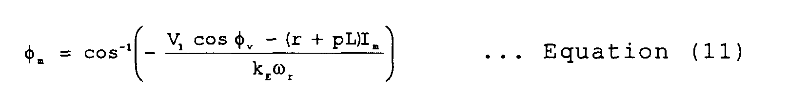
- the angle ⁇ m of the right-angled triangle can be determined pursuant to the following three equations (10) to (12) as below.
- the expanded functions are used in which the output range of the function is extended to - ⁇ to ⁇ [rad].
- the inverse function of the trigonometric function used in the present embodiment is the aforementioned expanded function.
- the phase ⁇ m can be determined from the quantities that are independent of the control axis. Further, in the present embodiment, the frequency of the AC voltage applied to the motor is so modified as to make the phase error ⁇ ⁇ zero on the basis of the magnitude of the phase error ⁇ ⁇ . By controlling the frequency in this manner, the control axis representing the virtual rotary axis can be rotated in phase with the rotor of the motor.
- the rotation direction of the motor rotor is exemplified as being positive but in the case of the inverse rotation direction, the phase ⁇ m can be determined similarly by taking the sign of the denominator and numerator into consideration when expanding the output range of the function to - ⁇ to ⁇ [rad] during calculation of the ⁇ m .
- ⁇ r - ( LI m ⁇ V 1 sin ⁇ v )+ ( LI m ⁇ V 1 sin ⁇ v ) 2 +( k E 2 -( LI m ) 2 ) ⁇ ( V 1 sin ⁇ v ) 2 +( V 1 cos ⁇ v -( r+pL ) I m ) 2 ⁇ ( k E 2 - ( LI m ) 2 )
- the term indicative of the current change component pL ⁇ I m can be neglected if the response of the control system is high, and the values of the resistance r and ⁇ L can be neglected if they are sufficiently smaller than other values.
- the observation currents iu and iw delivered out of the motor current detector 42 and the phase ⁇ dc delivered out of the frequency/phase preparation and speed detection unit 62 are delivered to an operating section 601.
- the operating section 601 two-phase currents i ⁇ and i ⁇ on the fixed coordinate axis are computed from the iu and iw, and then the currents I dc and I qc on the dc-qc coordinate axis are computed using the phase ⁇ dc .
- the current I dc is inputted to a filter 602.
- the current I dcf resulting from the removal of the high frequency components from the observation current I dc is computed.
- the current I qc is inputted to a filter 603.
- the current I qcf resulting from the removal of the high frequency components from the observation current I qc is computed.
- the filters 602 and 603 operate to eliminate the switching ripple and noise contained in the motor current.
- Time constant T ID of the filter is set to a predetermined value conforming to the switching frequency of the inverter and the circuit specifications of the motor current detector 42.
- the phase ⁇ m is calculated pursuant to equation (10). This calculation differs from the calculation of the axis error ⁇ ⁇ described previously in that as the motor voltage V 1 , the motor winding resistance r and motor winding inductance L representing the motor constants are needed for the calculation of phase ⁇ m , the command value V 1 * for the motor voltage, the motor winding resistance setting value r c and the motor winding inductance setting value L c are used, respectively, and that the motor speed command ⁇ r * is used for the rotation speed ⁇ r . Besides, on the assumption that the response of the control system is sufficiently high, the term of the current change component (pL ⁇ I m ) is neglected.
- the observation currents I dcf and I qcf delivered out of the coordinate converter 60 are inputted to the operating sections 611 and 612.
- the phase ⁇ c is computed pursuant to equation (15).
- phase ⁇ c as above is inputted to the operating sections 612 and 613.
- the magnitude I m of the motor current is computed pursuant to equation (16).
- I m -I dcf ⁇ sin ⁇ c +I qcf ⁇ cos ⁇ c
- the motor voltage command V 1 * and phase ⁇ c delivered out of the inverse-converting unit 65 are inputted to the operating section 613.
- the motor speed command ⁇ r * delivered out of the start/operation manager 66 is also inputted to the operating section 613.
- the phase error ⁇ ⁇ is computed from the inputted V 1 *, I m , ⁇ r *, ⁇ c and ⁇ c as well as the motor winding resistance setting value r c and the motor winding inductance setting value L c pursuant to equation (17).
- phase error ⁇ ⁇ delivered out of the phase error operating unit 61 and the phase error command ⁇ ⁇ * delivered out of the phase adjuster 69s are inputted to an adder 621, and difference ( ⁇ ⁇ *)- ⁇ ⁇ is computed.
- the difference ( ⁇ ⁇ *)- ⁇ ⁇ is inputted to a PI compensator 622.
- the PI compensator 622 cooperates with a limiter 623 to compute inverter output frequency ⁇ 1 .
- the inverter output frequency ⁇ 1 is inputted to a filter 624 in which the high-frequency change components are removed from the frequency ⁇ 1 to compute the motor speed ⁇ r .
- the inverter output frequency ⁇ 1 , the selecting signal sel delivered out of the start/operation manager 66, and the starting speed signal ⁇ 1s are inputted to a selector 625.
- the ⁇ 1s is selected and delivered when the selecting signal sel is "starting interval" indicative of a positioning initial rotation mode to be described later, but the ⁇ 1 is selected and delivered when the selecting signal is "normal operation interval" indicative of a position-sensorless operation mode to be described later.
- a frequency ⁇ 1sel selectively delivered out of the selector 625 is inputted to an operating section 626.
- the phase ⁇ dc is computed on the basis of the value of the frequency ⁇ 1sel .
- the PI compensator 622 computes the inverter output frequency ⁇ 1 such that the ⁇ ⁇ follows the ⁇ ⁇ *. Means different from the PI compensator but having a similar function may be used.
- a predetermined fixed value exceeding a rated frequency can be set as the upper limit value.
- the polarity of the upper limit value is inversed to provide a value to which the lower limit value is set, and the thus set lower limit value is used as a limit value when the motor rotation direction is inversed.
- the output of the PI compensator 622 constantly changes, thus containing the high-frequency components. Accordingly, when the speed control of the motor is carried out using the output of the PI compensator 622 as a detection speed of the motor, the speed control characteristic is degraded. Therefore, in the present embodiment, the low-pass filter 624 is provided in order that the detection speed of the motor removed of the high-frequency components can be obtained.
- the phase ⁇ dc is determined on the basis of the inputted frequency. It will be appreciated that in the operating section 626 shown in Fig. 6, the computation procedure of the frequency/phase preparation and speed detection unit 62 is executed by software, and computation is carried out at a time interval of control frequency ⁇ t. In the phase computation, the previous phase ⁇ dc (i-1) is added by ⁇ 1sel ⁇ ⁇ t to provide the present phase ⁇ dc (i).
- the output of the PI compensator 622 contains the high-frequency components responsible for adjustment of the motor detection speed and the phase error ⁇ ⁇ . For this reason, for determination of the detection speed, the output of the PI compensator 622 as it is cannot be used for the speed control, and the high-frequency components are removed by means of the low-pass filter. As another embodiment, a method will now be described in which the motor rotation speed is estimated to dispense with the low-pass filter.
- the inverter output frequency ⁇ 1 is determined as the sum of the first and second frequencies, the first frequency is defined as a motor speed determined pursuant to equation (14) by using the magnitude of the motor current, the magnitude of the motor voltage, the phase difference between the motor current and the motor voltage, the motor induced voltage constant, the motor winding resistance and the motor winding inductance.
- the second frequency is defined as a frequency for making ⁇ ⁇ equal to ⁇ ⁇ *.
- ⁇ r - (L c I m •V 1 *sin ⁇ v ) + (L c I m •V 1 *sin ⁇ v ) 2 + (k Ec 2 - (L c I m ) 2 )• ⁇ (V 1 *sin ⁇ v ) 2 + (V 1 *cos ⁇ v - r c I m ) 2 ⁇ (k Ec 2 - (L c I m ) 2 )
- the PI compensator 622 inputted with the difference between ⁇ ⁇ * and ⁇ ⁇ is combined with a limiter 623 to compute the second frequency ⁇ p11 .
- the motor detection speed ⁇ r and the second frequency ⁇ p11 are inputted to an adder 628, and the sum of the two is computed to deliver the inverter output frequency ⁇ 1 .
- the output of the PI compensator 622 is the high-frequency components responsible for adjustment of the phase error ⁇ ⁇ . Accordingly, the upper limit and lower limit values of the limiter 623 can be smaller than those of the limiter shown previously in Fig. 6.
- phase error ⁇ ⁇ is made to be conformable to the phase error command ⁇ ⁇ * and consequently, the inverter output frequency is modified by means of the PI compensator 622.
- a still another method will now be described in which the phase error ⁇ ⁇ is made to be conformable to the phase error command ⁇ ⁇ * by directly modifying the computed phase ⁇ dc .
- Fig. 8 Still another example of construction of the frequency/phase preparation and speed detection unit 62 is illustrated in Fig. 8. Here, portions different from those in Fig. 7 will be explained in connection with signal connection and flow.
- the detection signal ⁇ r , the selecting signal sel and the starting speed signal ⁇ 1s are inputted to the selector 625.
- the selector 625 selects ⁇ r or ⁇ 1s in accordance of the value of the selecting signal sel to deliver the selection speed ⁇ 1sel .
- a phase is computed on the basis of the value of the frequency of ⁇ 1sel .
- the output phase of the operating section 626 and the output ( ⁇ ⁇ *)- ⁇ ⁇ of the adder 621 are inputted to an adder 628, and the phase ⁇ dc is delivered.
- the phase delivered out of the operating section 626 is directly modified by the amount of the phase shift ( ⁇ ⁇ *)- ⁇ ⁇ delivered out of the adder 621. Consequently, the PI compensator and limiter needed for the example in Fig. 7 can be dispensed with to decrease the amount of the operation in the controller.
- the speed command ⁇ r * delivered out of the start/operation manager 66 and the detection speed ⁇ r delivered out of the frequency/phase preparation and speed detection unit 62 are inputted to an adder 631.
- ( ⁇ r *)- ⁇ r is computed, and the difference is inputted to the PI compensator 632.
- the current command value is computed which causes the ⁇ r to follow the ⁇ r *.
- the output of the PI compensator 632 is inputted to a limiter 633.
- the inputted value is subjected to the limit operation so as not to exceed the precedently set upper limit and lower limit values, and q-axis current command I q * is delivered.
- the starting d-axis current command I ds * the starting q-axis current command I qs * and the starting speed command ⁇ 1s are selected and delivered when the selecting signal sel indicates "starting interval" and the d-axis current command I d * , the q-axis current command I q * and the detection speed ⁇ r are selected and delivered when the selecting signal sel indicates normal operation interval".
- the d-axis current command I ds * or I d * selected by the selector 640 and the d-axis current I dcf delivered out of the coordinate converter 60 are inputted to an adder 641, and a difference between the two is computed.
- a compensation voltage for making the output of the adder 641 zero is computed.
- the compensation voltage is inputted to a limiter 645 in which its value is so processed as not to exceed the precedently set upper limit and lower limit values, and d-axis compensation voltage VI q is delivered out of the limiter.
- the q-axis current command 1 qs * or I q * selected by the selector 640 and the q-axis current I qcf delivered out of the coordinate converter 60 are inputted to an adder 642, and a difference between the two is computed.
- a PI compensator 644 a compensation voltage for making the output of the adder 642 zero is computed.
- the compensation voltage is inputted to a limiter 646, and processed such that its value does not excess the precedently set upper limit and lower limit values, and q-axis compensation voltage VI q is delivered out of the limiter.
- the d-axis current command I ds * or I d * is inputted to a motor voltage model 647, and d-axis model voltage V d * and q-axis model voltage V q * are delivered .
- I d * I d *
- I q * and ⁇ r are used for the motor voltage model
- the d-axis and q-axis model voltages are expressed by the following equation.
- V d * r c I d *- ⁇ r L c I q *
- V q * ⁇ r L c I d *+ r c I q *+ K Ec ⁇ r
- the motor voltage models can be derived from equation (1), and as compared to equation (1), the current change term is omitted, the voltage and the current are all replaced with the command values, and the motor constants are all replaced with the setting values.
- the d-axis compensation voltage VI d and the d-axis model voltage V d * are inputted to an adder 648, and the sum of the two is delivered as dc-axis voltage command V d ** .
- the q-axis compensation voltage VI q and the q-axis model voltage V q * are inputted to an adder 649, and the sum of the two is delivered as qc-axis voltage command V q ** .
- the d-axis compensation voltage VI d and the q-axis compensation voltage VI q produce certain values even during an accelerating/ decelerating operation or a normal operation, and in other cases, they have values of zero.
- the inverse-converting unit 65 shown in Fig. 11 receives the control axis voltage commands V d ** and V q ** to generate three-phase voltage commands.
- the dc-axis voltage command V d ** and qc-axis voltage command V q ** delivered out of the current controller 64 are inputted to an operating section 651.
- phase ⁇ c of the motor voltage V 1 as viewed from the qc-axis is computed pursuant to equation (9).
- the phase ⁇ c , the dc-axis voltage command V d ** and the qc-axis voltage command V q ** are inputted to an operating section 652.
- the magnitude V 1 * of the voltage command is computed.
- phase ⁇ c and the phase ⁇ dc are inputted to an operating section 653, and phase ⁇ v is computed.
- phase ⁇ v and the magnitude V 1 * of the voltage command are inputted to an operating section 654, and three-phase voltage commands V u * , V v * and V w * are computed.
- the phase ⁇ dc indicates the phase of the virtual rotor flux axis (dc-axis ) as viewed from the stator U-phase winding axis
- phase ⁇ v computed in the operating section 653 indicates the phase of the output voltage vector.
- the positioning time T p , current target value I mo , initial rotation time Is, initial frequency ⁇ iso , accelerating time T ac and setting frequency ⁇ r ** delivered out of the interface 67 are inputted to a sequence operating section 661.
- the setting values are inputted and the command values conforming to a lapse time are computed.
- the output values of the sequence operating section 661 are computed pursuant to equation (20).
- phase command ⁇ c * and current command I m * delivered out of the sequence operating section are inputted to an operating section 662 in which dc-axis current commands I ds * and I qs * during positioning and initial rotation are computed pursuant to equation (21).
- the permanent magnet motor can be started by sequentially changing control modes, three in total, including a positioning mode that proceeds from the motor operation start to the expiration of time T p , an initial rotation mode that proceeds from the end of the positioning mode to the expiration of time T s and a position-sensorless operation mode that proceeds after the initial rotation mode has ended.
- control modes three in total, including a positioning mode that proceeds from the motor operation start to the expiration of time T p , an initial rotation mode that proceeds from the end of the positioning mode to the expiration of time T s and a position-sensorless operation mode that proceeds after the initial rotation mode has ended.
- the frequency/phase preparation and speed detection unit 62 and the current controller 64 perform the control operations conforming to the individual control modes. Accordingly, the selecting signal sel conforming to the control mode is delivered.
- the voltage phase and the current commands change with the individual control modes as will be described below.
- the frequency ⁇ 1s is fixed to zero, so that the voltage phase is fixed to a precedently set, predetermined value, and remains unchanged.
- the frequency ⁇ 1s gradually increases and consequently, the voltage phase changes in the rotation direction.
- the current command I m * is fixed to I mo but the phase ⁇ c * changes from - ⁇ /2 to 0.
- the speed control shown in Fig. 9 is not carried out. Accordingly, after the control mode has returned to change to the position-sensorless operation mode, the value of the motor speed command ⁇ r * is delivered to the speed controller 63.
- At least one of the values of positioning time T p , current target value I mo , initial rotation time T s , initial frequency ⁇ 1s0 and setting frequency ⁇ r ** can be changed in its setting value. This permits the motor to be started steadily even when the motor constants change or the load condition changes.
- the setting value can be changed by the operation through the operator 7.
- Fig. 13 shows the behavior of the motor driven starting with motor operation initiation and going through the three control modes (positioning mode, initial rotation mode and position-sensorless control mode (normal operation mode)).
- position-sensorless control mode the frequency changes owing to four main causes, that is, acceleration, deceleration, increased load and decreased load as shown in the figure.
- the motor rotation frequency is indicated in terms of a motor electrical angle frequency.
- the difference between the inverter output frequency and the motor rotation frequency is determined in the aforementioned items (3) to (6) because in the frequency/phase preparation and speed detection unit 62, the inverter output frequency is caused to follow the motor rotation frequency so as to make the phase error ⁇ ⁇ coincident with the phase error command ⁇ ⁇ * .
- the phase ⁇ m is determined using the command value V 1 * for the motor voltage, the motor winding resistance setting value r c , the motor winding inductance setting value L c and the motor speed command ⁇ r *. If, of them, the motor winding resistance setting value r c and motor winding inductance setting value L c representing the motor constants, and the voltage command value V 1 * deviate from the actual values, the phase ⁇ m determined through the computation differs from the actual value, thereby bringing about a steady error in the phase error ⁇ ⁇ .
- two methods for reduction of the error will be described below, of which one uses d-axis compensation voltage VI d and q-axis compensation voltage VI q , and the other adjusts the phase so as to minimize the motor current.
- Equation (28) contains an inductance error and a voltage error. In the presence of only one of these errors, this error can be estimated using equation (28).
- the compensation voltage VI d for the d-axis current control, the compensation voltage VI q for the q-axis current control and the dq-axis current commands I d * and I q * , computed in the current controller 64 and delivered therefrom, and the speed command ⁇ r * are inputted to the parameter estimating unit 68L.
- the frequency command/inductance product ( ⁇ r * ) ⁇ L c used in the operating section 613 in Fig. 5 and the actual shift amount ⁇ r * ⁇ dL are computed.
- the compensation voltage VI d for the d-axis current control, the compensation voltage VI q for the q-axis current control and the dq-axis voltage commands V d ** and V q ** , computed in the current controller 64 and delivered therefrom, as well as the magnitude V 1 * of the motor voltage and the command speed ⁇ r * are inputted to the parameter estimating unit 68V.
- the shift amount dV between the magnitude V 1 * of the motor voltage used in the operating section 613 in Fig. 5 and the actual value is computed.
- dV can be obtained pursuant to equation (30). Then, this value is subtracted from V 1 * in equation (17) for the phase error operating unit shown in Fig. 5 so as to reflect a correct voltage upon the equation.
- equation (30) two different values can be obtained by either addition of the results of square root operation or subtraction of the results of square root operation. One of these values is selected in accordance with the magnitude of the error.
- phase adjusters 69I and 69S exemplified in the overall construction diagram of Fig. 1 are used.
- the phase adjusters 69I and 69S will now be described by making reference to Fig. 16.
- the operation result of the phase error ⁇ ⁇ contains the error due to parameter error. Because of this error, the phase of the dc-qc axis rotary coordinates cannot coincide with the d-q rotary coordinates, and the steady axis shift ⁇ ⁇ e remains.
- the current controller 64 controls the current to cause it to flow in only the q-axis direction by making the dc-axis current command I d * zero, but when the real axis shifts from the control axis, current flows also in the d-axis direction shown by the solid lines to decrease the torque current component in the q-axis direction correspondingly. As the axis shift ⁇ ⁇ e increases, the torque current component decreases.
- the speed is decreased to cause the speed controller 63 to increase the torque current command I q * and eventually, the magnitude I m of the motor current increases owing to the axis shift.
- the magnitude I m of the motor current is minimized.
- the motor current phase is adjusted so that the current may flow at the phase at which the magnitude I m of the current is minimized.
- a predetermined value is set to the exciting current command value I d * .
- the phase of the motor current can be changed arbitrarily.
- a predetermined value is set to the phase error command ⁇ ⁇ *.
- the first method can be implemented by the phase adjuster 69I, and the second method can implemented by the phase controller 69S.
- the setting value used during (i+1)-th control period will be selected as the value of I d * or ⁇ ⁇ * .
- the setting value for minimizing the motor current I m can be searched.
- the optimum solution searching algorithm such as the known Newton-Raphson method can be used to determine the setting value.
- the phase angle is expressed by the value not depending on the position of the control axis to determine the phase error, so that the position-sensorless control system of the synchronous motor which can be stable even when the large phase error occurs during, for example, the abrupt load change or the abrupt accelerating/decelerating operation can be provided.
Abstract
Description


Consequently, the PI compensator and limiter needed for the example in Fig. 7 can be dispensed with to decrease the amount of the operation in the controller.


Claims (15)
- A position-sensorless controlling method of synchronous motor comprising the steps of:determining a first phase difference (m) between a motor current of a synchronous motor (3) having a field system of a permanent magnet and an actual rotation phase;determining a second phase difference (c) between said motor current and a virtual rotation phase; andestimating a phase error (Δ ) between said actual rotation position and said virtual rotation position from a difference between said first phase difference and said second phase difference.
- A position-sensorless controlling method of synchronous motor according to claim 1, wherein said second phase difference (c) is determined using a motor voltage (V1), said motor current (Im) and motor constants (r, L).
- A position-sensorless controlling method of synchronous motor according to claim 1 further comprising the step of modifying a frequency (ω1) of an AC voltage applied to said synchronous motor (3) to cause said phase error (Δ ) to approach zero.
- A position-sensorless controlling method of synchronous motor for estimating a rotor position of a synchronous motor (3) having a field system of a permanent magnet and being driven by an inverter circuit (24), comprising the steps of:determining a first phase difference (m) between a motor current and an actual rotation phase by using magnitude (Im) of motor current, magnitude (V1) of motor voltage, a phase difference (v) between said motor current and said motor voltage, and motor constants (r, L);determining a second phase difference (c) between said motor current and a virtual rotation phase; andmodifying an estimation position such that said first phase difference (m) equals to said second phase difference (c).
- A position-sensorless controlling method of synchronous motor according to claim 4, whereinsaid first phase difference (m) is calculated bydecomposing an induced voltage (Eo) into a current in-phase induced voltage component in phase with the motor current and a current orthogonal induced voltage component with a phase which differs 90° from a phase of the motor current;determining said current in-phase induced voltage component and said current orthogonal induced voltage component using the magnitude (Im) of the motor current, the magnitude (V1 *) of the motor voltage, the phase difference (v) between the motor current and the motor voltage, and at least one of a motor winding resistance (r) and a motor winding inductance (L); andusing at least two values of the three of said current in-phase induced voltage component, said current orthogonal induced voltage component, and the magnitude of the induced voltage.
- A position-sensorless controlling method of synchronous motor according to claim 4, wherein the estimation position is modified by modifying an inverter output frequency (ω1) such that said first phase difference (m) equals to said second phase difference (c).
- A position-sensorless controlling method of synchronous motor according to claim 6, whereinsaid inverter output frequency (ω1) is a sum of first and second frequencies (ωr and ωp11), said first frequency (ωr) is a frequency concerning a rotation speed determined by using one of magnitude (Im) of motor current, magnitude (V1 *) of motor voltage, phase difference (v) between the motor current and the motor voltage, motor induced voltage constant, and at least one of motor winding resistance ( r ) and motor winding inductance (L); andsaid second frequency is a frequency determined such that said first phase difference (m) equals to said second phase difference (c).
- A position-sensorless controlling method of synchronous motor according to claim 6, wherein said inverter output frequency (ω1) is attenuated in its high-frequency components and thereafter used as a detection speed which in turn is compared with a command speed (ωr *) to control the motor voltage.
- A position-sensorless controlling method of synchronous motor according to claim 7, said first frequency (ωr) is used as a detection speed which in turn is compared with a command speed (ωr *) to control the motor voltage.
- A position-sensorless controlling method of synchronous motor according to claim 1, whereinmotor voltage or motor constants are estimated by using a q axis compensation voltage (VIq) for q-axis current control adapted to make a torque current component of the motor current in phase with an induced voltage coincident with a torque current command, and a d-axis compensation voltage (VId) for d-axis current control adapted to make an exciting current component of the motor current orthogonal to the induced voltage coincident with an exciting current command; andsaid first phase difference (m) is determined using estimation values.
- A position-sensorless controlling method of synchronous motor for estimating a rotor position of a synchronous motor (3) having a field system of a permanent magnet and being driven by an inverter circuit (24), comprising:
the step of adjusting a current phase in a direction in which magnitude (Im) of a motor current is minimized. - A position-sensorless controlling method of synchronous motor according to claim 11, whereincurrent control is performed to make an exciting current component orthogonal to an induced voltage due to the motor current coincident to an exciting current command; andsaid current phase is adjusted by adjusting said exciting current command.
- A position-sensorless controlling method of synchronous motor for estimating a rotor position of a synchronous motor (3) having a field system of a permanent magnet and being driven by an inverter circuit (24), wherein;three control modes of positioning mode, initial rotation mode and position-sensorless operation mode occurring in sequence from operation initiation are provided;in said positioning mode, a voltage phase is arbitrarily fixed to gradually raise a current applied to a motor winding to a predetermined current value;in said initial rotation mode, the voltage phase is rotated in a rotation direction to raise to a predetermined inverter output frequency; andin said position-sensorless operation mode, a difference between motor current and an actual rotation phase is determined as a first phase difference (m) from three values of magnitude of the motor current, magnitude of motor voltage and a phase difference between the motor current and the motor voltage through computation, a difference between the motor current and a virtual rotation phase is determined as a second phase difference (c) through computation, and an estimation position is modified such that said first phase difference (m) coincides with said second phase difference (c).
- A position-sensorless controlling method of synchronous motor according to claim 13, wherein time (Tp) for said positioning mode and said predetermined current value is changeable, and time (Ts) for said initial rotation mode and said predetermined inverter output frequency is changeable.
- A position-sensorless controlling method of synchronous motor for estimating a rotor position of a synchronous motor (3) having a field system of a permanent magnet and being driven by an inverter circuit (24), comprising the step of:
making inverter output frequency follow a motor electrical angle frequency to estimate a motor position, by decreasing the inverter output frequency below the motor electrical angle frequency during acceleration of the synchronous motor, increasing the inverter output frequency above the motor electrical angle frequency during deceleration of the synchronous motor, and increasing the inverter output frequency above the motor electrical angle frequency during increasing load on the synchronous motor, and decreasing the inverter output frequency below the motor electrical angle frequency during decreasing the load on the synchronous motor.
Applications Claiming Priority (2)
| Application Number | Priority Date | Filing Date | Title |
|---|---|---|---|
| JP33928699 | 1999-11-30 | ||
| JP33928699A JP3454210B2 (en) | 1999-11-30 | 1999-11-30 | Position sensorless control method for synchronous motor |
Publications (2)
| Publication Number | Publication Date |
|---|---|
| EP1107446A2 true EP1107446A2 (en) | 2001-06-13 |
| EP1107446A3 EP1107446A3 (en) | 2003-10-08 |
Family
ID=18326026
Family Applications (1)
| Application Number | Title | Priority Date | Filing Date |
|---|---|---|---|
| EP00119017A Withdrawn EP1107446A3 (en) | 1999-11-30 | 2000-09-01 | Position-sensorless controlling method of synchronous motor |
Country Status (3)
| Country | Link |
|---|---|
| US (1) | US6462492B1 (en) |
| EP (1) | EP1107446A3 (en) |
| JP (1) | JP3454210B2 (en) |
Cited By (8)
| Publication number | Priority date | Publication date | Assignee | Title |
|---|---|---|---|---|
| DE10332228A1 (en) * | 2003-07-16 | 2005-02-24 | Ebm-Papst Mulfingen Gmbh & Co. Kg | Control method for brushless electric motor, especially fan motor, in which motor is operated as brushless DC motor during acceleration phase and as synchronous motor during constant speed phase |
| EP1753125A2 (en) | 2005-08-11 | 2007-02-14 | Hitachi, Ltd. | Vector controller for permanent magnet synchronous motor |
| US7221152B2 (en) | 2003-09-05 | 2007-05-22 | Abb Oy | Method in salient-pole permanent magnet synchronous machine |
| EP1873901A2 (en) * | 2006-06-28 | 2008-01-02 | Sanyo Electric Co., Ltd. | Motor control device |
| EP2284544A1 (en) * | 2009-08-04 | 2011-02-16 | Robert Bosch GmbH | Method and device for measuring the rotational speed of an electric motor without sensors |
| EP1758240A3 (en) * | 2005-08-26 | 2011-06-29 | Sanyo Electric Co., Ltd. | Motor control device |
| CN107102537A (en) * | 2017-05-04 | 2017-08-29 | 武汉滨湖电子有限责任公司 | A kind of double lead synchronisation control means based on virtual main shaft |
| WO2018082902A1 (en) * | 2016-11-02 | 2018-05-11 | Robert Bosch Gmbh | Method for determining a rotational angle position of a crankshaft of an internal combustion engine |
Families Citing this family (80)
| Publication number | Priority date | Publication date | Assignee | Title |
|---|---|---|---|---|
| AU2403002A (en) * | 2000-11-09 | 2002-05-21 | Daikin Ind Ltd | Synchronous motor control method and device |
| JP3529752B2 (en) * | 2001-02-16 | 2004-05-24 | 本田技研工業株式会社 | DC brushless motor rotor angle detector |
| JP4687846B2 (en) * | 2001-03-26 | 2011-05-25 | 株式会社安川電機 | Magnetic pole position estimation method and control apparatus for synchronous motor |
| JP4672236B2 (en) * | 2001-04-24 | 2011-04-20 | 三菱電機株式会社 | Control device for synchronous motor |
| JP3867518B2 (en) | 2001-06-06 | 2007-01-10 | 株式会社日立製作所 | Sensorless control system for synchronous motor |
| JP4075338B2 (en) * | 2001-07-18 | 2008-04-16 | 株式会社豊田自動織機 | Control method of electric compressor |
| JP4665360B2 (en) * | 2001-08-06 | 2011-04-06 | 株式会社安川電機 | Electric motor control device |
| JP3668870B2 (en) * | 2001-08-09 | 2005-07-06 | 株式会社日立製作所 | Synchronous motor drive system |
| JP2003079200A (en) * | 2001-09-04 | 2003-03-14 | Hitachi Ltd | Motor drive system |
| JP3501370B2 (en) * | 2001-09-04 | 2004-03-02 | 株式会社デンソー | Control method and control device for synchronous motor |
| ITMI20012835A1 (en) * | 2001-12-28 | 2003-06-28 | Abb Service Srl | PROCEDURE FOR DETERMINING THE ROTOR POSITION OF A SYNCHRONOUS ALTERNATING CURRENT MACHINE WITH PERMANENT MAGNETS |
| JP4319377B2 (en) * | 2002-05-31 | 2009-08-26 | 三菱電機株式会社 | Permanent magnet motor drive device, hermetic compressor, refrigeration cycle device, and permanent magnet generator drive device |
| KR20040018716A (en) * | 2002-08-26 | 2004-03-04 | 삼성전자주식회사 | Apparatus and method for controlling velocity of BLDC motor |
| JP4059039B2 (en) * | 2002-08-30 | 2008-03-12 | 株式会社安川電機 | Control device for synchronous motor |
| US6856109B2 (en) * | 2002-10-15 | 2005-02-15 | International Rectifier Corporation | Efficiency optimization control for permanent magnet motor drive |
| US6979967B2 (en) * | 2002-10-15 | 2005-12-27 | International Rectifier Corporation | Efficiency optimization control for permanent magnet motor drive |
| JP3783695B2 (en) * | 2003-03-20 | 2006-06-07 | 日産自動車株式会社 | Motor control device |
| JP4235482B2 (en) * | 2003-04-22 | 2009-03-11 | オリエンタルモーター株式会社 | Control device for position control motor |
| CN100448158C (en) * | 2003-04-30 | 2008-12-31 | 松下电器产业株式会社 | Motor driving apparatus |
| JP4039317B2 (en) * | 2003-06-12 | 2008-01-30 | 株式会社ジェイテクト | Electric power steering device |
| JP4475903B2 (en) * | 2003-09-12 | 2010-06-09 | サンデン株式会社 | Motor control device |
| WO2005034327A1 (en) * | 2003-09-30 | 2005-04-14 | Mitsubishi Denki Kabushiki Kaisha | Inverter apparatus |
| US7053587B2 (en) * | 2004-02-10 | 2006-05-30 | Denso Corporation | Apparatus for controlling three-phase AC motor on two-phase modulation technique |
| ITTO20040399A1 (en) * | 2004-06-16 | 2004-09-16 | Univ Catania | CONTROL SYSTEM AND METHOD FOR ELECTRIC DRIVES WITH AC MOTORS. |
| US7068001B2 (en) * | 2004-07-29 | 2006-06-27 | Japan Servo Co., Ltd. | Motor control system |
| KR100600751B1 (en) * | 2004-08-12 | 2006-07-14 | 엘지전자 주식회사 | Sensorless motor drive and it's protection method |
| KR20070074623A (en) * | 2004-10-29 | 2007-07-12 | 캐리어 코포레이션 | Vsd control |
| US7211984B2 (en) * | 2004-11-09 | 2007-05-01 | General Motors Corporation | Start-up and restart of interior permanent magnet machines |
| JP4589093B2 (en) * | 2004-12-10 | 2010-12-01 | 日立オートモティブシステムズ株式会社 | Synchronous motor driving apparatus and method |
| KR101041076B1 (en) * | 2004-12-17 | 2011-06-13 | 삼성전자주식회사 | Method for control starting of brushless DC motor |
| KR20060070911A (en) * | 2004-12-21 | 2006-06-26 | 삼성전자주식회사 | Starting apparatus of a bldc motor and method thereof |
| WO2006092265A1 (en) * | 2005-03-04 | 2006-09-08 | Ebm-Papst St. Georgen Gmbh & Co. Kg | Electric motor and method for controlling said motor |
| DE102005013773A1 (en) * | 2005-03-22 | 2006-09-28 | Diehl Ako Stiftung & Co. Kg | Electronic motor regulation for pump used in e.g. dishwasher, involves detecting and estimating rotor phase position and rotor speed of motor and determining fluctuations in rotor phase position and rotor speed to control pump operation |
| KR101234825B1 (en) * | 2005-05-13 | 2013-02-20 | 삼성전자주식회사 | Apparatus and method for controlling linear compressor |
| JP4425193B2 (en) * | 2005-08-16 | 2010-03-03 | 三洋電機株式会社 | Motor position sensorless control device |
| JP2007116859A (en) * | 2005-10-24 | 2007-05-10 | Toyo Electric Mfg Co Ltd | Phase presumption device of synchronous motor |
| JP4416764B2 (en) * | 2006-06-29 | 2010-02-17 | 株式会社日立製作所 | Vector controller and inverter module for permanent magnet motor |
| JP2008086117A (en) * | 2006-09-27 | 2008-04-10 | Aisin Seiki Co Ltd | Electric fluid pump |
| JP2008131730A (en) * | 2006-11-20 | 2008-06-05 | Matsushita Electric Ind Co Ltd | Semiconductor device, motor drive unit and air conditioner |
| EP2015443B1 (en) * | 2007-07-10 | 2010-04-07 | Jtekt Corporation | Motor control device |
| US8950206B2 (en) | 2007-10-05 | 2015-02-10 | Emerson Climate Technologies, Inc. | Compressor assembly having electronics cooling system and method |
| US7895003B2 (en) * | 2007-10-05 | 2011-02-22 | Emerson Climate Technologies, Inc. | Vibration protection in a variable speed compressor |
| US8418483B2 (en) * | 2007-10-08 | 2013-04-16 | Emerson Climate Technologies, Inc. | System and method for calculating parameters for a refrigeration system with a variable speed compressor |
| US8448459B2 (en) * | 2007-10-08 | 2013-05-28 | Emerson Climate Technologies, Inc. | System and method for evaluating parameters for a refrigeration system with a variable speed compressor |
| US20090092502A1 (en) * | 2007-10-08 | 2009-04-09 | Emerson Climate Technologies, Inc. | Compressor having a power factor correction system and method |
| US8459053B2 (en) | 2007-10-08 | 2013-06-11 | Emerson Climate Technologies, Inc. | Variable speed compressor protection system and method |
| US8539786B2 (en) * | 2007-10-08 | 2013-09-24 | Emerson Climate Technologies, Inc. | System and method for monitoring overheat of a compressor |
| US20090092501A1 (en) * | 2007-10-08 | 2009-04-09 | Emerson Climate Technologies, Inc. | Compressor protection system and method |
| US9541907B2 (en) * | 2007-10-08 | 2017-01-10 | Emerson Climate Technologies, Inc. | System and method for calibrating parameters for a refrigeration system with a variable speed compressor |
| KR101372533B1 (en) * | 2007-11-20 | 2014-03-11 | 엘지전자 주식회사 | Motor controller of air conditioner |
| JP5130031B2 (en) * | 2007-12-10 | 2013-01-30 | 株式会社日立製作所 | Position sensorless control device for permanent magnet motor |
| JP5175569B2 (en) * | 2008-02-07 | 2013-04-03 | ルネサスエレクトロニクス株式会社 | Synchronous motor drive system |
| US20090310272A1 (en) * | 2008-06-17 | 2009-12-17 | Global Energy Savings, Inc. | Energy savings and surge protection device |
| RU2470453C1 (en) * | 2009-03-25 | 2012-12-20 | Мицубиси Электрик Корпорейшн | Control device for electric rotary machine |
| US20100259230A1 (en) * | 2009-04-13 | 2010-10-14 | Boothroyd Howard G | Power factor correction device with adjustable capacitance |
| JP5317849B2 (en) * | 2009-06-25 | 2013-10-16 | サンデン株式会社 | Motor control device |
| KR101470025B1 (en) * | 2009-07-06 | 2014-12-15 | 현대자동차주식회사 | A model based sensorless vector control method of PMSM using an adaptive observer |
| JP5182302B2 (en) * | 2010-02-08 | 2013-04-17 | 株式会社デンソー | Rotating machine control device |
| PL2410653T3 (en) * | 2010-07-23 | 2019-09-30 | Askoll Holding S.R.L. | Device for controlling a synchronous electric motor with a permanent magnet rotor |
| EP2626996B1 (en) * | 2010-10-08 | 2022-06-15 | Panasonic Holdings Corporation | Motor constant calculating method for pm motor, and motor constant calculating device |
| WO2012049770A1 (en) * | 2010-10-15 | 2012-04-19 | 東芝三菱電機産業システム株式会社 | Synchronous machine activation device |
| JP5898407B2 (en) | 2011-02-15 | 2016-04-06 | サンデンホールディングス株式会社 | Motor control device |
| JP5838032B2 (en) | 2011-02-15 | 2015-12-24 | サンデンホールディングス株式会社 | Motor control device |
| GB2489434A (en) * | 2011-03-25 | 2012-10-03 | Technelec Ltd | Controlling an electrical machine with an observer |
| US8779711B2 (en) * | 2011-04-20 | 2014-07-15 | Princeton Power Systems, Inc. | Induction motor driver |
| JP5748051B2 (en) * | 2011-05-10 | 2015-07-15 | サンデンホールディングス株式会社 | Synchronous motor applied voltage electrical angle setting method and motor control device |
| US9046543B2 (en) | 2011-06-22 | 2015-06-02 | Lexmark International, Inc. | Method and apparatus for measuring speed of a brush motor |
| JP5824918B2 (en) * | 2011-07-04 | 2015-12-02 | 日産自動車株式会社 | Inverter control device and inverter control method |
| US8860342B2 (en) | 2011-09-15 | 2014-10-14 | Curtiss-Wright Electro-Mechanical Corporation | System and method for controlling a permanent magnet motor |
| DE102011113780A1 (en) * | 2011-09-19 | 2013-03-21 | Magna Electronics Europe Gmbh & Co.Kg | Method for controlling a permanent-magnet synchronous motor |
| US9391538B2 (en) | 2011-09-21 | 2016-07-12 | Princeton Power Systems, Inc. | Switched power converter |
| CN104137414A (en) * | 2012-02-24 | 2014-11-05 | 株式会社安川电机 | Motor control apparatus |
| JP5970227B2 (en) * | 2012-04-17 | 2016-08-17 | 日立オートモティブシステムズ株式会社 | Synchronous motor drive system |
| JP5920635B2 (en) * | 2013-08-20 | 2016-05-18 | 株式会社デンソー | AC motor control device |
| US9595903B2 (en) | 2015-03-20 | 2017-03-14 | General Electric Company | Controller for motor |
| CN106533281A (en) * | 2015-09-11 | 2017-03-22 | 德昌电机(深圳)有限公司 | Electric tool and motor driving circuit thereof |
| DE102018217111B4 (en) * | 2018-10-05 | 2021-05-20 | Robert Bosch Gmbh | Method for determining a rotational angle position of a crankshaft of an internal combustion engine |
| US10879825B2 (en) * | 2019-04-01 | 2020-12-29 | Naroller Electronics Co., Ltd. | Sensorless position measurement system for permanent magnet machine and measuring method thereof |
| US11206743B2 (en) | 2019-07-25 | 2021-12-21 | Emerson Climate Technolgies, Inc. | Electronics enclosure with heat-transfer element |
| US20230253898A1 (en) * | 2022-02-04 | 2023-08-10 | Texas Instruments Incorporated | Observer-Based Ripple Detection for Speed and Position Measurement for Brushed Direct Current Motors |
Citations (3)
| Publication number | Priority date | Publication date | Assignee | Title |
|---|---|---|---|---|
| US5530326A (en) * | 1993-07-19 | 1996-06-25 | Quantum Corporation | Brushless DC spindle motor startup control |
| JPH08308286A (en) * | 1995-05-10 | 1996-11-22 | Toyota Motor Corp | Angular velocity of rotation detector for synchronous motor, angle velocity of rotation and controller and controlling method for the motor |
| JPH09191698A (en) * | 1996-01-12 | 1997-07-22 | Yaskawa Electric Corp | Method for presuming speed of permanent magnet synchronous motor, method for presuming slip angle of its rotor and method for correcting rotor position |
Family Cites Families (2)
| Publication number | Priority date | Publication date | Assignee | Title |
|---|---|---|---|---|
| WO1996003797A1 (en) * | 1994-07-25 | 1996-02-08 | Daikin Industries, Ltd. | Motor apparatus capable of obtaining high efficiency and motor control method |
| EP0982844B1 (en) * | 1996-08-19 | 2009-06-03 | Daikin Industries, Limited | Synchronous motor driving device |
-
1999
- 1999-11-30 JP JP33928699A patent/JP3454210B2/en not_active Expired - Fee Related
-
2000
- 2000-09-01 EP EP00119017A patent/EP1107446A3/en not_active Withdrawn
- 2000-09-05 US US09/655,490 patent/US6462492B1/en not_active Expired - Lifetime
Patent Citations (3)
| Publication number | Priority date | Publication date | Assignee | Title |
|---|---|---|---|---|
| US5530326A (en) * | 1993-07-19 | 1996-06-25 | Quantum Corporation | Brushless DC spindle motor startup control |
| JPH08308286A (en) * | 1995-05-10 | 1996-11-22 | Toyota Motor Corp | Angular velocity of rotation detector for synchronous motor, angle velocity of rotation and controller and controlling method for the motor |
| JPH09191698A (en) * | 1996-01-12 | 1997-07-22 | Yaskawa Electric Corp | Method for presuming speed of permanent magnet synchronous motor, method for presuming slip angle of its rotor and method for correcting rotor position |
Non-Patent Citations (9)
| Title |
|---|
| CONSOLI A ET AL: "SENSORLESS VECTOR AND SPEED CONTROL OF BRUSHLESS MOTOR DRIVES" IEEE TRANSACTIONS ON INDUSTRIAL ELECTRONICS, IEEE INC. NEW YORK, US, vol. 41, no. 1, 1 February 1994 (1994-02-01), pages 91-95, XP000452269 ISSN: 0278-0046 * |
| KHABURI D A ET AL: "A DSP-BASED CONTROLLER FOR SENSORLESS CONTROL OF SYNCHRONOUS MACHINES" EPE '97. 7TH. EUROPEAN CONFERENCE ON POWER ELECTRONICS AND APPLICATIONS. TRONDHEIM, SEPT. 8 - 10, 1997, EPE. EUROPEAN CONFERENCE ON POWER ELECTRONICS AND APPLICATIONS, BRUSSELS, EPE ASSOCIATION, B, vol. 4 CONF. 7, 8 September 1997 (1997-09-08), pages 4547-4552, XP000768195 ISBN: 90-75815-02-6 * |
| KIM Y-H ET AL: "HIGH PERFORMANCE IPMSM DRIVES WITHOUT ROTATIONAL POSITION SENSORS USING REDUCED-ORDER EKF" IEEE TRANSACTIONS ON ENERGY CONVERSION, IEEE INC. NEW YORK, US, vol. 14, no. 4, December 1999 (1999-12), pages 868-873, XP000931916 ISSN: 0885-8969 * |
| KRISHNAN R, GHOSH R: "Starting algorithm and performance of a PM DC brushless motor drive system with no position sensor" PESC '89 RECORD. 20TH ANNUAL IEEE POWER ELECTRONICS SPECIALISTS, vol. 2, 26 June 1989 (1989-06-26), pages 815-821, XP010085428 Milwaukee, WI, USA * |
| MATSUI N: "Sensorless operation of brushless DC motor drives" INDUSTRIAL ELECTRONICS, CONTROL, AND INSTRUMENTATION, 1993. PROCEEDINGS OF THE IECON '93., INTERNATIONAL CONFERENCE ON MAUI, HI, USA 15-19 NOV. 1993, NEW YORK, NY, USA,IEEE, 15 November 1993 (1993-11-15), pages 739-744, XP010109131 ISBN: 0-7803-0891-3 * |
| PATENT ABSTRACTS OF JAPAN vol. 1997, no. 03, 31 March 1997 (1997-03-31) & JP 08 308286 A (TOYOTA MOTOR CORP), 22 November 1996 (1996-11-22) * |
| PATENT ABSTRACTS OF JAPAN vol. 1997, no. 11, 28 November 1997 (1997-11-28) & JP 09 191698 A (YASKAWA ELECTRIC CORP), 22 July 1997 (1997-07-22) * |
| SENJYU T ET AL: "Vector control of permanent magnet synchronous motors without position and speed sensors" POWER ELECTRONICS SPECIALISTS CONFERENCE, 1995. PESC '95 RECORD., 26TH ANNUAL IEEE ATLANTA, GA, USA 18-22 JUNE 1995, NEW YORK, NY, USA,IEEE, US, 18 June 1995 (1995-06-18), pages 759-765, XP010150638 ISBN: 0-7803-2730-6 * |
| WATANABE H ET AL: "An improved measuring system of rotor position angles of the sensorless direct drive servomotor" PROCEEDINGS OF THE INTERNATIONAL CONFERENCE ON INDUSTRIAL ELECTRONICS,CONTROL AND INSTRUMENTATION (IECON). KOBE, OCT. 28 - NOV. 1, 1991, NES YORK, IEEE, US, vol. 1 CONF. 17, 28 October 1991 (1991-10-28), pages 165-170, XP010042117 ISBN: 0-87942-688-8 * |
Cited By (15)
| Publication number | Priority date | Publication date | Assignee | Title |
|---|---|---|---|---|
| DE10332228A1 (en) * | 2003-07-16 | 2005-02-24 | Ebm-Papst Mulfingen Gmbh & Co. Kg | Control method for brushless electric motor, especially fan motor, in which motor is operated as brushless DC motor during acceleration phase and as synchronous motor during constant speed phase |
| DE10332228B4 (en) * | 2003-07-16 | 2013-09-19 | Ebm-Papst Mulfingen Gmbh & Co. Kg | Control method for a brushless electric motor, in particular fan motor |
| US7221152B2 (en) | 2003-09-05 | 2007-05-22 | Abb Oy | Method in salient-pole permanent magnet synchronous machine |
| EP1753125A2 (en) | 2005-08-11 | 2007-02-14 | Hitachi, Ltd. | Vector controller for permanent magnet synchronous motor |
| EP1753125A3 (en) * | 2005-08-11 | 2009-05-06 | Hitachi, Ltd. | Vector controller for permanent magnet synchronous motor |
| EP1758240A3 (en) * | 2005-08-26 | 2011-06-29 | Sanyo Electric Co., Ltd. | Motor control device |
| EP2432115A1 (en) * | 2005-08-26 | 2012-03-21 | Sanyo Electric Co., Ltd. | Motor control device |
| EP1873901A2 (en) * | 2006-06-28 | 2008-01-02 | Sanyo Electric Co., Ltd. | Motor control device |
| CN101098117B (en) * | 2006-06-28 | 2010-10-20 | 三洋电机株式会社 | Motor control device |
| US7679308B2 (en) | 2006-06-28 | 2010-03-16 | Sanyo Electric Co., Ltd. | Motor control device |
| EP1873901A3 (en) * | 2006-06-28 | 2009-10-21 | Sanyo Electric Co., Ltd. | Motor control device |
| EP2284544A1 (en) * | 2009-08-04 | 2011-02-16 | Robert Bosch GmbH | Method and device for measuring the rotational speed of an electric motor without sensors |
| WO2018082902A1 (en) * | 2016-11-02 | 2018-05-11 | Robert Bosch Gmbh | Method for determining a rotational angle position of a crankshaft of an internal combustion engine |
| CN107102537A (en) * | 2017-05-04 | 2017-08-29 | 武汉滨湖电子有限责任公司 | A kind of double lead synchronisation control means based on virtual main shaft |
| CN107102537B (en) * | 2017-05-04 | 2021-08-06 | 武汉滨湖电子有限责任公司 | Double-screw synchronous control method based on virtual main shaft |
Also Published As
| Publication number | Publication date |
|---|---|
| JP2001161090A (en) | 2001-06-12 |
| EP1107446A3 (en) | 2003-10-08 |
| JP3454210B2 (en) | 2003-10-06 |
| US6462492B1 (en) | 2002-10-08 |
Similar Documents
| Publication | Publication Date | Title |
|---|---|---|
| US6462492B1 (en) | Position-sensorless controlling method of synchronous motor | |
| EP1133050B1 (en) | Method of estimating a rotor position of synchronous motor, method of controlling synchronous motor with no position sensor and a controller of synchronous motor | |
| US6570358B2 (en) | Control apparatus for alternating-current motor | |
| EP1128543B1 (en) | Synchronous motor-control apparatus and vehicle using the control apparatus | |
| EP1808956B1 (en) | Driving apparatus and driving system for electric motor | |
| EP1662650B1 (en) | Synchronous motor control method and synchronous motor control system | |
| EP1796260B1 (en) | Vector controller of induction motor | |
| US5994867A (en) | Method and device for controlling a sensorless field-oriented asynchronous machine | |
| EP2007004B1 (en) | Induction motor drive unit, motor drive system, and elevating system | |
| EP2696496B1 (en) | Motor control device | |
| US20010028236A1 (en) | Speed control apparatus for synchronous reluctance motor | |
| JP2009232498A (en) | Motor control device | |
| JP2008220096A (en) | Sensorless controller of synchronous electric motor | |
| JP2007318894A (en) | Device and method for detecting phase shift of magnetic pole position sensor for synchronous motor | |
| KR19990086188A (en) | Estimation of stator and rotor resistance values in induction motors | |
| JPH07107772A (en) | Drive control circuit of permanent magnet-type synchronous motor | |
| KR100563225B1 (en) | Induction Motor Control System | |
| JPH1127996A (en) | Current vector control method for ac motor and ac motor drive device | |
| JP5392532B2 (en) | Induction motor control device | |
| JP7024289B2 (en) | Motor control device | |
| JP5307578B2 (en) | Electric motor control device | |
| JP3698149B2 (en) | Position sensorless control method for synchronous motor | |
| TWI756975B (en) | Motor driving method | |
| WO2022137650A1 (en) | Motor control device and motor control method | |
| JP3299416B2 (en) | Vector control method of induction motor |
Legal Events
| Date | Code | Title | Description |
|---|---|---|---|
| PUAI | Public reference made under article 153(3) epc to a published international application that has entered the european phase |
Free format text: ORIGINAL CODE: 0009012 |
|
| AK | Designated contracting states |
Kind code of ref document: A2 Designated state(s): AT BE CH CY DE DK ES FI FR GB GR IE IT LI LU MC NL PT SE |
|
| AX | Request for extension of the european patent |
Free format text: AL;LT;LV;MK;RO;SI |
|
| RIC1 | Information provided on ipc code assigned before grant |
Ipc: 7H 02P 21/00 B Ipc: 7H 02P 6/18 A |
|
| PUAL | Search report despatched |
Free format text: ORIGINAL CODE: 0009013 |
|
| RIC1 | Information provided on ipc code assigned before grant |
Ipc: 7H 02P 6/20 B Ipc: 7H 02P 21/00 B Ipc: 7H 02P 6/18 A |
|
| AK | Designated contracting states |
Kind code of ref document: A3 Designated state(s): AT BE CH CY DE DK ES FI FR GB GR IE IT LI LU MC NL PT SE |
|
| AX | Request for extension of the european patent |
Extension state: AL LT LV MK RO SI |
|
| AKX | Designation fees paid | ||
| REG | Reference to a national code |
Ref country code: DE Ref legal event code: 8566 |
|
| STAA | Information on the status of an ep patent application or granted ep patent |
Free format text: STATUS: THE APPLICATION IS DEEMED TO BE WITHDRAWN |
|
| 18D | Application deemed to be withdrawn |
Effective date: 20040409 |