EP1109983B1 - Anschraubscharnier mit raststellung - Google Patents
Anschraubscharnier mit raststellung Download PDFInfo
- Publication number
- EP1109983B1 EP1109983B1 EP99941634A EP99941634A EP1109983B1 EP 1109983 B1 EP1109983 B1 EP 1109983B1 EP 99941634 A EP99941634 A EP 99941634A EP 99941634 A EP99941634 A EP 99941634A EP 1109983 B1 EP1109983 B1 EP 1109983B1
- Authority
- EP
- European Patent Office
- Prior art keywords
- hinge
- screw
- sleeve
- spring
- hinge part
- Prior art date
- Legal status (The legal status is an assumption and is not a legal conclusion. Google has not performed a legal analysis and makes no representation as to the accuracy of the status listed.)
- Expired - Lifetime
Links
Images

Classifications
-
- E—FIXED CONSTRUCTIONS
- E05—LOCKS; KEYS; WINDOW OR DOOR FITTINGS; SAFES
- E05D—HINGES OR SUSPENSION DEVICES FOR DOORS, WINDOWS OR WINGS
- E05D11/00—Additional features or accessories of hinges
- E05D11/10—Devices for preventing movement between relatively-movable hinge parts
- E05D11/1028—Devices for preventing movement between relatively-movable hinge parts for maintaining the hinge in two or more positions, e.g. intermediate or fully open
- E05D11/1078—Devices for preventing movement between relatively-movable hinge parts for maintaining the hinge in two or more positions, e.g. intermediate or fully open the maintaining means acting parallel to the pivot
-
- E—FIXED CONSTRUCTIONS
- E05—LOCKS; KEYS; WINDOW OR DOOR FITTINGS; SAFES
- E05D—HINGES OR SUSPENSION DEVICES FOR DOORS, WINDOWS OR WINGS
- E05D5/00—Construction of single parts, e.g. the parts for attachment
- E05D5/10—Pins, sockets or sleeves; Removable pins
-
- E—FIXED CONSTRUCTIONS
- E05—LOCKS; KEYS; WINDOW OR DOOR FITTINGS; SAFES
- E05D—HINGES OR SUSPENSION DEVICES FOR DOORS, WINDOWS OR WINGS
- E05D7/00—Hinges or pivots of special construction
- E05D7/10—Hinges or pivots of special construction to allow easy separation or connection of the parts at the hinge axis
- E05D7/1005—Hinges or pivots of special construction to allow easy separation or connection of the parts at the hinge axis by axially moving free pins, balls or sockets
-
- E—FIXED CONSTRUCTIONS
- E05—LOCKS; KEYS; WINDOW OR DOOR FITTINGS; SAFES
- E05Y—INDEXING SCHEME RELATING TO HINGES OR OTHER SUSPENSION DEVICES FOR DOORS, WINDOWS OR WINGS AND DEVICES FOR MOVING WINGS INTO OPEN OR CLOSED POSITION, CHECKS FOR WINGS AND WING FITTINGS NOT OTHERWISE PROVIDED FOR, CONCERNED WITH THE FUNCTIONING OF THE WING
- E05Y2800/00—Details, accessories and auxiliary operations not otherwise provided for
- E05Y2800/26—Form, shape
-
- E—FIXED CONSTRUCTIONS
- E05—LOCKS; KEYS; WINDOW OR DOOR FITTINGS; SAFES
- E05Y—INDEXING SCHEME RELATING TO HINGES OR OTHER SUSPENSION DEVICES FOR DOORS, WINDOWS OR WINGS AND DEVICES FOR MOVING WINGS INTO OPEN OR CLOSED POSITION, CHECKS FOR WINGS AND WING FITTINGS NOT OTHERWISE PROVIDED FOR, CONCERNED WITH THE FUNCTIONING OF THE WING
- E05Y2900/00—Application of doors, windows, wings or fittings thereof
- E05Y2900/10—Application of doors, windows, wings or fittings thereof for buildings or parts thereof
- E05Y2900/13—Application of doors, windows, wings or fittings thereof for buildings or parts thereof characterised by the type of wing
- E05Y2900/132—Doors
-
- E—FIXED CONSTRUCTIONS
- E05—LOCKS; KEYS; WINDOW OR DOOR FITTINGS; SAFES
- E05Y—INDEXING SCHEME RELATING TO HINGES OR OTHER SUSPENSION DEVICES FOR DOORS, WINDOWS OR WINGS AND DEVICES FOR MOVING WINGS INTO OPEN OR CLOSED POSITION, CHECKS FOR WINGS AND WING FITTINGS NOT OTHERWISE PROVIDED FOR, CONCERNED WITH THE FUNCTIONING OF THE WING
- E05Y2900/00—Application of doors, windows, wings or fittings thereof
- E05Y2900/10—Application of doors, windows, wings or fittings thereof for buildings or parts thereof
- E05Y2900/13—Application of doors, windows, wings or fittings thereof for buildings or parts thereof characterised by the type of wing
- E05Y2900/146—Shutters
Definitions
- the invention relates to a screw-on hinge for a vertical or horizontal a frame or wall pivotably arranged door or flap, in which the Door or flap is detachably held in at least one swivel angle position, consisting of a first z. B. hinge part attachable to the frame, and a second z. B. hinge part attachable to the door or flap, which Hinge parts are symmetrical about their median bisector and one each Include hole for receiving a hinge pin assembly, the Hinge pin assembly comprises a sleeve which is rotationally rigid with the one hinge part is connected and between which sleeve and the other hinge part one resilient locking device is arranged.
- Hinge part provided radially aligned to the hinge axis bore spaces open at one end to the sleeve and pick up the ball there while the other end of the hole can be closed by a slide which is then supported by the compression spring.
- the disadvantage here is that a special Configuration of the at least one hinge part (hinge flap) is necessary, which special configuration for an increased overall height of the hinge part leads.
- DE 29 41 860 A1 which corresponds to the preamble of claim 1, is a hinge consisting of two hinge parts known in which the hinge pin is formed by a sleeve in which one Compression spring is arranged, which is provided with the end of the projections with the a hinge part torsionally rigid sleeve against one in the other Hinge part arranged, with radial notches insert presses to to obtain an elastic locking at certain angles of rotation.
- the disadvantage is that the two hinge parts are not axially fixable to each other and therefore the hinge only in connection with a second, opposite hinge Type can be used (p. 6, lines 16-21).
- DE 23 42 945 also describes a hinge for a motor vehicle door, the has a locking device.
- a coil compression spring 10 which by a second Coaxially arranged compression spring 9 can be reinforced with radial Depressions provided, with the one hinge part 3 rotationally rigidly connected Control plates against pins 11, 12 which are guided transversely through the hinge pin 6 pressed which hinge pin is torsionally rigid with the other hinge part 1 are connected.
- DE-OS 22 35 555 discloses hinge tapes for a hinge with locking Coaxial and arranged on the hinge pin (plate) springs (claim 2).
- the object of the invention is to avoid the above disadvantages and a Screw-on hinge to create the one mentioned has a simpler construction, is more compact in its outer shape, fewer individual parts includes, is largely symmetrical, and therefore easier to assemble, and that has a longer lifespan.
- the hinge pin device is in two parts and that one end of a hinge part facing the other hinge part, the Forms locking device, and that the locking device from a sleeve end face is formed and includes an axially disposed within the sleeve coil spring.
- the sleeve face also provides a contour surface is available which has a locking device with a relatively lower Surface pressure enables what reduces material wear and the Lifetime of the hinge increased.
- the locking device comprises one at the end the hole for the hinge pin formed or arranged in the hinge part Shoulder or blind hole bottom surface in which depressions or elevations are provided for elevations or depressions of the sleeve face correspond, the compression spring the sleeve with its elevations or Depressions against the shoulder or floor surface with their depressions and Elevations (recesses, protrusions) presses.
- the torsionally rigid Connection between the one hinge part and the hinge pin by a tongue and groove device is obtained, or alternatively by non-circular, for example prismatic cross-sectional shape of the cross-section of the hinge pin on the one hand and the hole in the hinge part in which this hinge pin is to be inserted, on the other hand.
- a particularly stable and nevertheless simple form of a hinge is one those in which the one hinge part the other hinge part fork-shaped encloses, as can also be seen in the prior art.
- the sleeve-shaped hinge pin is executed in two parts and one end of a hinge pin part, which End to the other hinge pin part, which carries the locking device.
- both hinge pin parts of the two-part hinge pin accordingly their ends are provided with locking projections or locking recesses, which in engaging corresponding recesses or protrusions from ring shoulders are formed in the hinge part bore in which the corresponding ends of the Hinge pin parts are included.
- the other end of the hinge pin parts can then in the hinge pin hole of the other hinge part torsionally rigid, but possibly sliding in the axial direction be included.
- the sliding recording ensures that it can dodge in the axial direction while engaging and disengaging.
- the spring device for the latching device also has two parts is executed, in particular the spring ends of a screw penetrating the spring parts can be held, whereby one spring on the head of the screw and the other spring on one on the Screw screwed nut could support.
- This has the great advantage that the force with which the locking devices exert the holding force, not from parts of the Hinge must be included and this additional hinge parts load, but by the screw, which otherwise has no holding function can be applied.
- the stability of the Overall arrangement greatly enlarged.
- the two forks of the fork-shaped hinge part relieved of bending forces.
- the depressions or noses (projections) formed by the shoulder should also be in this case four times and a distance of 90 degrees to have.
- the coordination of these lugs (projections) or depressions with each other leads to a particularly stable hinge shape and a particularly high one Holding force in the different locking positions.
- the latching device can also be designed such that the spring pressure of the coil spring within a small to the click point lying angle of rotation to a torque in the direction of the rest point leads, and that the orientation of a locking point for the closed position in such a way is taken that when the door or flap is closed, the rest point is not quite is reached and therefore there is a torque acting in the closing direction.
- the door is held in its closed position with a certain pressure so that there is no rattling or play movement, as might be the case, when the door is in the closed position exactly at the zero point of the rest position.
- hinge parts are designed in such a way that they open mutually aligned fastening surfaces of the frame on the one hand and the door or Flap are screwed on the other hand.
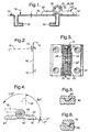
- Fig. 1 is a screw hinge 10 for one vertically or horizontally on one Frame or a wall 12 door or pivotally arranged about an axis 14
- Detect flap 16 in at least one swivel angle position for example is releasably held in one of the positions shown in FIG. 4.
- the Screw-on hinge 10 consists of a first one, for example on the frame or on the wall 12 attachable hinge part 18, the attachment for example could be done by means of two axially offset countersunk screws 20, see corresponding countersunk holes 22 in Figs. 3 and 4. Corresponding Holes can be found in a second, e.g. B. on the door or flap 16 screw-on hinge part 24. Both hinge parts 18, 24 each have one Bore 26, 28, see FIGS. 7 and 9, into which a hinge pin device 30 is recordable.
- the conditions can be seen again in a reduced representation, the solid line the closed door or flap can be seen within the wall or frame 12, and dashed at 90 ° pivots to show another position, which can be a releasably held position like.
- 2 may be a machine cover 12, and that Hinge 10 hold a flap 16 which can be pivoted about a horizontal axis is opened in the dashed representation in the horizontal direction and for example, access to the engine room allowed for maintenance purposes.
- FIG. 1 may represent a door 16 that is about a vertical axis 14 can be opened and closed, with sealing strips 32 are indicated, which are placed on edges of the frame or wall 12 and when the door 16 is closed, a tight one together with folds in the door Allow closure of the openings closed by the door 16.
- the sleeve part 34 has at its lower end 36 in FIG. 11 an axially aligned, radially projecting ledge or spring 38, which in a corresponding groove 40 can be received, which is in the area of the first hinge part 18 Hinge pin bore 26 formed in the area of the fastening tab 42 returns.
- this tongue and groove connection serves the sleeve 34 each in the bore 26 of the two ends of the To keep hinge part 18 rigid, but axially displaceable.
- the other end 44 has an annular end face in which four depressions offset by 90 ° 46 are arranged.
- the sleeve 34 forms an axial bore 48 which is close to the End 44 narrowed to a bore 50 of smaller diameter.
- a larger compression spring 52 can be accommodated, which is shown in FIG. 14 is shown and on the shoulder 54 formed by the narrowing to the bore 50 can support.
- the narrower bore 50 in turn allows one in FIG. 15 Pass screw bolt 56 shown, as in the following is described.
- the upper end of the sleeve 34 with the end surface having the depressions 46 is receivable in a bore 28, which is in Fig. 9 with respect to the second hinge part 24 is shown.
- This hole also forms a first hole area larger diameter, the sleeve 34 rotatably and axially displaceably and a second bore region 60 forming an annular shoulder 58 smaller diameter, the diameter of which is sufficient to turn the shaft to be able to pass through the bolt 56.
- the annular shoulder 58 carries according to Fig. 10, a bottom view of the part of FIG.
- the first hinge part 18 is designed so that it with its two Legs 66 engages around the inner part 68 of the second hinge part 24, whereby after corresponding bores 26 of the two legs 66 of the first Hinge part 18 to the two existing, to the hinge part center 67th symmetrically arranged bores 28 of the second hinge part 24 are aligned.
- This position can be from the outside in the bores 26 of the first hinge part 18th each a sleeve part 34 with its side 44 having the narrower bore 50 be inserted ahead until this side 44 in the bore 28 of the second Hinge part 24 has penetrated and fills, with component 34 at the same time its spring part 38 is aligned so that this spring 38 moves into the groove 40.
- This assembled position can be seen in Fig. 3.
- the length of the cap screw 56 is expediently chosen so that it disappears within the hinge parts.
- the hinge gets one aesthetic appearance, since the built-in locking device is not visible.
- a hinge according to FIG. 4 is such trained that it shows locking points at -5 °, at 85 ° and at 175 °.
- the frame or wall pushes the door into position 0 °, whereby Contact pressure arises.
- the door stays in the open position, the door leaf projecting substantially perpendicularly from the fastening surface.
- the hinge shown here this large opening angle allows (see the dashed line in Fig. 4), since it is a 180 ° hinge is.
- the cylinder screw 56 compressing the springs 52 enables through Tightening or loosening the nut 72 an adjustment of the pressure force and thus the Adjustment strength. You can do without this adjustability, instead of Cylinder screw 56 also a rivet of suitable length and diameter use, for example in the form of a hollow rivet, one of which is the rivet head Function of the screw head and its other rivet head that of the nut of the Cylinder screw takes over.
- the hinge parts can be injection molded from metal or preferably from plastic.
- the locking surfaces, if made of plastic, result in low coefficients of friction. For higher ones Resilience can also be favorable, the locking surfaces from a metal part form, which is inserted or injected into the plastic.
- the hinge pin device it is also possible to make the hinge pin device out of two nested ones Build up sleeves, the outer, first sleeve being fixed to the one hinge part is connected (such as pressed, glued), so that this sleeve with respect to the Hinge is not axially displaceable in the assembled state.
- the inner second sleeve is axially displaceable and rotatable.
- the one outer sleeve may then protrude radially inwards Ring shoulder which form a locking surface, while the other, inner sleeve the one on it forms a rotating, corresponding second locking surface, this sleeve in suitably rigid, but axially displaceable with the other hinge part connected is.
- the inner sleeve then contains the spring, which is the locking surfaces of the press the two sleeves together.
- the spring is penetrated by a retaining bolt or holding rivet, the latter possibly also in the form of a sleeve.
- This arrangement is special stable and enables a hinge with hinge flaps made of plastic, into which the e.g. sleeves made of metal are embedded, of particularly great strength.
- the invention can be evaluated commercially in control cabinet construction.
Description
in einer Querschnittsansicht eine dünne Wand mit einer durch eine Klappe verschließbaren Öffnung, welche Klappe durch ein erfindungsgemäß ausgestaltetes Scharnier an der dünnen Wand gehalten wird;
in verkleinerter Darstellung die in Fig. 1 dargestellte Klappe in um 90° geöffneter, in dieser Stellung arretierter Haltestellung;
eine Draufsicht auf das Scharnier mit geschnittenem Axialstift;
eine Ansicht von oben auf das Scharnier der Fig. 3;
in einer vergrößerten Darstellung den Arretierungsbereich gemäß einer ersten Stellung (Nullstellung);
den entsprechenden Bereich in einer zweiten (von der Nullstellung abweichenden) Stellung zur Erzeugung eines Drehmoments in Schließrichtung;
in einer Einzelteildarstellung das eine Scharnierteil, das mit zwei Gabelzinken das in Fig. 9 dargestellte andere Scharnierteil umgreift;
eine Ansicht von oben auf das in Fig. 7 dargestellte umgreifende eine Scharnierteil;
das umgriffene andere Scharnierteil in einer Draufsicht;
das umgriffene Scharnierteil gemäß Fig. 9 in einer Ansicht von oben;
die Seitenansicht eines hülsenartigen Scharnierstiftteils einer zweiteiligen Scharnierstiftanordnung, wie sie gemäß Fig. 3 verwendet wird;
eine Ansicht von unten auf das Scharnierstiftteil gemäß Fig. 11;
eine Ansicht von oben auf das in Fig. 11 dargestellte Scharnierstiftteil;
eine Seitenansicht auf die zugehörige Druckfeder, die in dem hülsenförmigen Scharnierstiftteil aufgenommen werden kann; und
eine Seitenansicht der zugehörigen Zylinderschraube mit Mutter, die die Federn der beiden Scharnierstiftteile zusammenpreßt.
Claims (19)
- Anschraubscharnier (10) für eine vertikal oder horizontal an einem Rahmen oder Wand (12) schwenkbar angeordnete Tür oder Klappe (16), bei dem die Tür oder Klappe (16) in zumindest einer Schwenkwinkelstellung (-5°; +85°; +175°) lösbar gehalten ist, bestehend aus einem ersten z.B. am Rahmen befestigbaren Scharnierteil (18), und einem zweiten z.B. an der Tür oder Klappe (16) befestigbaren Schamierteil (24), welche Scharnierteile (18,24) jeweils um ihre Mittelhalbierende (67) symmetrisch sind und jeweils eine Bohrung (26, 28) zur Aufnahme einer Scharnierstiftanordnung (30) umfassen, wobei die Scharnierstiftanordnung mindestens eine Hülse (34) umfaßt, die mit dem einen Scharnierteil (18) drehstarr verbunden ist, und zwischen welcher Hülse (34) und dem anderen Scharnierteil (24) eine federnde Rasteinrichtung angeordnet ist, dadurch gekennzeichnet, daß die Scharnierstifteinrichtung (30) zweiteilig ist und daß das eine Ende (44) des einen Scharnierteils, das zum anderen Scharnierteil weist, die Rasteinrichtung bildet, und daß die Rasteinrichtung jeweils von einer Hülsenstirnseite gebildet ist und jeweils eine achsial innerhalb der Hülse angeordnete Spiraldruckfeder (52) umfaßt.
- Anschraubschamier nach Anspruch 1, dadurch gekennzeichnet, daß die Rasteinrichtung eine am Ende der jeweiligen Bohrung (28) für den jeweiligen Scharnierstift (30) im Scharnierteil (24) gebildete oder angeordnete Schultern oder Sacklochbodenflächen (58) aufweist, in der Einsenkungen oder Erhebungen (Rücksprünge oder Vorsprünge) (46; 62) vorgesehen sind, die Erhebungen oder Einsenkungen (62, 46) der Hülsenstirnseite (46) zugeordnet sind, und daß die Feder (52) die Hülse (34) mit ihren Erhebungen oder Einsenkungen gegen die Schulter oder Bodenfläche mit deren Einsenkungen oder Erhebungen drückt.
- Anschraubscharnier nach Anspruch 1 oder 2, dadurch gekennzeichnet, daß die drehstarre Verbindung zwischen dem einen Schamierteil (z. B. 18) und dem Scharnierstift (z. B. 34) durch eine Nut-Feder-Einrichtung (38, 40) oder durch eine prismatische oder nicht runde Querschnittsform erreicht ist.
- Anschraubschamier nach einem der Ansprüche 1 bis 3, dadurch gekennzeichnet, daß das eine Scharnierteil (z. B. 18) das andere Scharnierteil (z. B. 24) gabelförmig umschließt.
- Anschraubscharnier nach einem der Ansprüche 1 - 4, dadurch gekennzeichnet, daß beide aufeinander weisenden Stimenden (40) der Scharnierteile (34) mit Vorsprüngen oder Rücksprüngen (62, 46) versehen sind, die in entsprechende Rücksprünge/Vorsprünge (46, 62) eingreifen, die von Ringschultern (58) in der Schamierteilbohrung gebildet sind, in die die entsprechenden Stimenden (44) aufgenommen sind.
- Anschraubscharnier nach Anspruch 5, dadurch gekennzeichnet, daß das jeweils andere Ende (36) der Scharnierstiftteile (34) in die Scharnierstiftbohrung (26) des anderen Scharnierteils (18) drehstarr, aber achsial gleitend aufgenommen ist.
- Anschraubscharnier nach einem der Ansprüche 1 bis 6, dadurch gekennzeichnet, daß die Feder zweiteilig ist und aus zwei Druckfedern (52) besteht.
- Anschraubschamier nach einem der Ansprüche 1 bis 7, dadurch gekennzeichnet, daß die voneinander weggerichteten Federenden der Druckfeder(n) (52) von einer die Federteile durchdringenden Schraube (56) zusammengedrückt werden, wobei sich die eine Feder auf den Kopf (70) der Schraube und die andere Feder auf eine aufgeschraubte Mutter (72) abstützt.
- Anschraubscharnier nach einem der Ansprüche 1 bis 8, dadurch gekennzeichnet, daß die Stirnfläche (44) der Hülse vier Vorsprünge-Rücksprünge (62, 46) aufweist, die voneinander einen Abstand von 90 Winkelgrad haben.
- Anschraubscharnier nach einem der Ansprüche 1 bis 9, dadurch gekennzeichnet, daß auch die von der Schulter (58) gebildeten Rücksprünge-Vorsprünge (46, 62) vierfach vorgesehen sind und einen Abstand von 90 Winkelgrad zueinander haben, wobei die 0°-Ausrichtung der Rücksprünge-Vorsprünge bezüglich der Befestigungsfläche des Scharniers (12) eine Verschiebung von einigen Graden, z. B. 5° aufweist.
- Anschraubscharnier nach Anspruch 10, dadurch gekennzeichnet, daß die Ausrichtung der Raststellen derart getroffen ist, daß bei Schließstellung der Tür oder Klappe diese Raststellung gerade erreicht ist.
- Anschraubscharnier nach Anspruch 10, dadurch gekennzeichnet, daß die Rasteinrichtung so ausgestaltet ist, daß der Federdruck der Spiralfeder innerhalb eines um den Rastpunkt herum liegenden Drehwinkels zu einem Drehmoment in Richtung des Rastpunktes führt, und daß die Ausrichtung des einen Rastpunktes für die Schließstellung derart getroffen ist, daß bei geschlossener Tür oder Klappe auf diese Tür oder Klappe ein in Schließrichtung wirkendes Drehmoment auftritt.
- Anschraubscharnier nach einem der Ansprüche 1 bis 12, dadurch gekennzeichnet, daß die Scharnierteile (18, 24) derart gestaltet sind, daß sie auf zueinander fluchtenden Befestigungsflächen (12, 16) von Rahmen und Tür oder Klappe aufschraubbar sind.
- Anschraubscharnier nach einem der Ansprüche 8 bis 13, dadurch gekennzeichnet, daß anstelle des Schraubbolzens ein Niet, wie Hohlniet, die Druckfedern zusammendrückt.
- Anschraubscharnier nach einem der Ansprüche 1 bis 14, dadurch gekennzeichnet, daß die Scharnierteile (18, 24) aus Kunststoff gespritzt sind.
- Anschraubschamier nach Anspruch 15, dadurch gekennzeichnet, daß die Rastflächen (58, 60) des einen Scharnierteils (24) von einem Metallteil gebildet ist, das in den Kunststoff eingelegt, insbesondere eingespritzt ist.
- Anschraubscharnier nach einem der Ansprüche 1 bis 16, dadurch gekennzeichnet, daß die Scharnierstifteinrichtung von einer mit dem einen Scharnierteil fest verbundenen ersten Hülse und einer mit dem anderen Scharnierteil drehstarr, aber axial verschieblich verbundenen zweiten Hülse gebildet wird, wobei die zweite Hülse in der ersten Hülse angeordnet ist und die erste Hülse eine nach innen radial vorspringende Ringschulter mit Rasteinrichtungen bildet, auf der die Stirnfläche der zweiten Hülse mit einer analogen Rasteinrichtung unter Federkraft aufliegt, welche Federkraft von einer innerhalb der zweiten Hülse angeordneten Spiraldruckfeder erzeugt wird.
- Anschraubscharnier nach Anspruch 17, dadurch gekennzeichnet, daß die beiden Hülsen aus unterschiedlichem Material, wie Metall und Kunststoff bestehen.
- Anschraubscharnier nach Anspruch 17 oder 18, dadurch gekennzeichnet, daß die Spiraldruckfeder(n) von einem Schraubbolzen oder Niet, insbesondere Hohlniet unter Spannung gehalten wird, der die Spiralfeder(n) durchgreift.
Applications Claiming Priority (3)
| Application Number | Priority Date | Filing Date | Title |
|---|---|---|---|
| DE29815747U DE29815747U1 (de) | 1998-09-02 | 1998-09-02 | Anschraubscharnier mit Raststellung |
| DE29815747U | 1998-09-02 | ||
| PCT/EP1999/006023 WO2000014371A1 (de) | 1998-09-02 | 1999-08-17 | Anschraubscharnier mit raststellung |
Publications (2)
| Publication Number | Publication Date |
|---|---|
| EP1109983A1 EP1109983A1 (de) | 2001-06-27 |
| EP1109983B1 true EP1109983B1 (de) | 2002-10-23 |
Family
ID=8062112
Family Applications (1)
| Application Number | Title | Priority Date | Filing Date |
|---|---|---|---|
| EP99941634A Expired - Lifetime EP1109983B1 (de) | 1998-09-02 | 1999-08-17 | Anschraubscharnier mit raststellung |
Country Status (4)
| Country | Link |
|---|---|
| US (1) | US6568032B1 (de) |
| EP (1) | EP1109983B1 (de) |
| DE (3) | DE29815747U1 (de) |
| WO (1) | WO2000014371A1 (de) |
Families Citing this family (15)
| Publication number | Priority date | Publication date | Assignee | Title |
|---|---|---|---|---|
| US7062817B2 (en) * | 2003-03-14 | 2006-06-20 | Winia Mando, Inc. | Hinge assembly structure for opening and closing of door of storage facility |
| US6708536B1 (en) * | 2003-03-25 | 2004-03-23 | Chia Yu Yu | Anti-theft device for vehicles |
| PL1711672T3 (pl) * | 2004-01-26 | 2008-06-30 | Dieter Ramsauer | Zawias do montażu w wycięciach |
| US6986188B2 (en) * | 2004-06-14 | 2006-01-17 | Shin Zu Shing Co., Ltd. | Hinge |
| US7275285B1 (en) * | 2004-11-15 | 2007-10-02 | Lockheed Martin Corporation | Deployment hinge |
| CN201187522Y (zh) * | 2008-03-10 | 2009-01-28 | 深圳富泰宏精密工业有限公司 | 铰链结构及应用该铰链结构的便携式电子装置 |
| NL2005520C2 (nl) * | 2010-10-14 | 2011-09-13 | Estem B V | Scharnier voor een paneeldeur, in het bijzonder voor een koelmeubel. |
| GB201114861D0 (en) * | 2011-08-29 | 2011-10-12 | Bedi Parkarman S | PSB-Hinge |
| US8556330B2 (en) * | 2012-01-13 | 2013-10-15 | Chrysler Group Llc | Removable door with hinge detent |
| US9776595B2 (en) * | 2015-06-10 | 2017-10-03 | Ford Global Technologies, Llc | Soft close safety belt tongue/latch plate stowage compartment |
| EP3257490A1 (de) | 2016-06-17 | 2017-12-20 | Sunrise Medical GmbH | Seitenhalter für eine haltungssitzstütze |
| CN109025582A (zh) * | 2018-09-25 | 2018-12-18 | 张卫 | 自锁式限位合页 |
| CN110566072A (zh) * | 2019-09-09 | 2019-12-13 | 兴化市广福金属制品有限公司 | 一种改进型便组装不锈钢合页 |
| US11746581B2 (en) * | 2021-10-04 | 2023-09-05 | GM Global Technology Operations LLC | Flip hinge |
| CN113982396B (zh) * | 2021-11-02 | 2023-06-02 | 浙江王力安防产品有限公司 | 一种铰链铰接结构 |
Family Cites Families (24)
| Publication number | Priority date | Publication date | Assignee | Title |
|---|---|---|---|---|
| US294746A (en) * | 1884-03-04 | Thomas p | ||
| US769035A (en) * | 1903-11-23 | 1904-08-30 | Harrison B Walter | Lock-hinge. |
| US975097A (en) * | 1910-03-26 | 1910-11-08 | Joseph Wright | Hinge. |
| US1078002A (en) * | 1911-09-18 | 1913-11-11 | Frederick Schrey | Hinge. |
| US1440713A (en) * | 1922-03-14 | 1923-01-02 | Merritt W Ausbourne | Self-locking hinge |
| US1465912A (en) * | 1922-07-19 | 1923-08-21 | Jensen Martin | Hinge |
| US1946837A (en) * | 1932-10-13 | 1934-02-13 | Clayton Walter | Doorcheck |
| US2097651A (en) * | 1936-12-07 | 1937-11-02 | Myer C Cohen | Ratchet hinge |
| US2182546A (en) * | 1938-08-05 | 1939-12-05 | Thomas E Raymond | Hinge |
| DE2235555A1 (de) * | 1972-07-20 | 1974-01-31 | Daimler Benz Ag | Scharnier mit arretierung, insbesondere fuer kraftfahrzeugtueren |
| GB1391215A (en) * | 1972-08-24 | 1975-04-16 | Ihw Eng Ltd | Door hinge |
| DE2418147A1 (de) * | 1974-04-13 | 1975-11-06 | Volkswagenwerk Ag | Scharnier, insbesondere fuer eine kraftfahrzeugtuer |
| CH625591A5 (en) * | 1978-10-17 | 1981-09-30 | Corthesy Gerald Orraco | Hinge |
| NO154582C (no) | 1978-10-20 | 1986-11-05 | Ferrosan Ab | Analogifremgangsmaate for fremstilling av terapeutisk aktive difenyl-dibutylpiperazinkarboksamider. |
| AT376004B (de) * | 1980-07-11 | 1984-10-10 | Grass Alfred Metallwaren | Scharnier mit einer zuhalte- und offenhaltevorrichtung fuer tueren u.dgl. |
| DE3624649A1 (de) * | 1986-07-22 | 1988-02-18 | Lunke & Sohn Gmbh | Tuerscharnier fuer ein kraftfahrzeug mit einem tuerfeststeller |
| DE8627459U1 (de) * | 1986-10-15 | 1987-11-19 | Lunke & Sohn Gmbh, 5810 Witten, De | |
| DE3905351A1 (de) * | 1989-02-22 | 1990-08-23 | Hueppe Gmbh & Co | Fluegeltuer, insbesondere in einer duschabtrennung |
| JP2534114Y2 (ja) * | 1991-09-30 | 1997-04-30 | 日本電気株式会社 | 折畳型電子機器の構造 |
| CA2062630C (en) | 1992-01-13 | 1995-06-13 | Allen Riblett | Detent hinge |
| DE19619473A1 (de) * | 1996-05-14 | 1997-11-20 | Scharwaechter Gmbh Co Kg | Mit einem aushängbaren Türscharnier baulich vereinigter Türfeststeller |
| US5715576A (en) * | 1997-02-04 | 1998-02-10 | Liu; Tai-Sheng | Hinge device for coupling two rotatable members |
| US5774938A (en) * | 1997-02-19 | 1998-07-07 | Erma W. Kent | Locking device for locking a closure in an open position |
| DE29709777U1 (de) | 1997-06-05 | 1997-09-18 | Breust Volker Dipl Designer | Scharnier für Ganzglasduschen |
-
1998
- 1998-09-02 DE DE29815747U patent/DE29815747U1/de not_active Expired - Lifetime
-
1999
- 1999-08-17 DE DE19981699T patent/DE19981699D2/de not_active Expired - Fee Related
- 1999-08-17 EP EP99941634A patent/EP1109983B1/de not_active Expired - Lifetime
- 1999-08-17 DE DE59903199T patent/DE59903199D1/de not_active Expired - Lifetime
- 1999-08-17 US US09/786,221 patent/US6568032B1/en not_active Expired - Fee Related
- 1999-08-17 WO PCT/EP1999/006023 patent/WO2000014371A1/de active IP Right Grant
Also Published As
| Publication number | Publication date |
|---|---|
| DE19981699D2 (de) | 2001-09-13 |
| EP1109983A1 (de) | 2001-06-27 |
| DE29815747U1 (de) | 2000-01-05 |
| WO2000014371A1 (de) | 2000-03-16 |
| DE59903199D1 (de) | 2002-11-28 |
| US6568032B1 (en) | 2003-05-27 |
Similar Documents
| Publication | Publication Date | Title |
|---|---|---|
| EP1109983B1 (de) | Anschraubscharnier mit raststellung | |
| EP1711672B1 (de) | Scharnier zur montage in einem durchbruch | |
| DE4292446C1 (de) | Scharnier | |
| EP1153186B1 (de) | Verschluss zur verbindung zweier dünner wände | |
| EP3612700A1 (de) | Möbelplatte mit einem klappenbeschlag und möbelkorpus sowie möbel mit einer derartigen möbelplatte | |
| DE19728641A1 (de) | Positionsscharnier für Türen | |
| EP1849937A2 (de) | Klipsbefestigung für die Schnellmontage von Beschlageinrichtungen, wie Schwenkhebelverschlüsse, Scharnierteile in Durchbrüchen in einer dünnen Wand | |
| DE2049743B2 (de) | Tuerverschluss | |
| EP0551872A2 (de) | Tür mit einem Fallen- und/oder Riegelschloss und Handhabenbeschlag dafür | |
| EP0783616A1 (de) | Stangenverschluss | |
| DE3418138C2 (de) | Bandzapfenbüchse | |
| DE19642637C2 (de) | Türscharnier zur schwenkbaren Lagerung eines Türflügels an einem Türrahmen | |
| EP1375803B1 (de) | Türscharnier insbesondere für Kraftfahrzeuge | |
| DE10152699B4 (de) | Möbelscharnier mit Öffnungsmechanik, insbesondere für Möbeltüren | |
| DE3412832C2 (de) | ||
| DE102008034070A1 (de) | Schließzylinder mit federkraftunterstützter Zylinderkernrückstellung | |
| WO1998059138A1 (de) | Scharnier für blechschranktüren | |
| DE102005057766B3 (de) | Beschlag für Türen, Fenster oder dergleichen | |
| EP0861953A1 (de) | Betätigungshandhabe | |
| EP0662559B1 (de) | Türband | |
| CH709360A2 (de) | Selbstschliessendes Rollentürband. | |
| DE3129851A1 (de) | Mehrteiliger moebelfuss aus kunststoff | |
| DE4103923C2 (de) | ||
| DE3109553A1 (de) | Haltevorrichtung fuer eine schwenktuer | |
| DE7819147U1 (de) | Schliessvorrichtung fuer eine pendeltuer |
Legal Events
| Date | Code | Title | Description |
|---|---|---|---|
| PUAI | Public reference made under article 153(3) epc to a published international application that has entered the european phase |
Free format text: ORIGINAL CODE: 0009012 |
|
| 17P | Request for examination filed |
Effective date: 20010220 |
|
| AK | Designated contracting states |
Kind code of ref document: A1 Designated state(s): AT BE CH CY DE DK ES FI FR GB GR IE IT LI LU MC NL PT SE |
|
| GRAG | Despatch of communication of intention to grant |
Free format text: ORIGINAL CODE: EPIDOS AGRA |
|
| 17Q | First examination report despatched |
Effective date: 20011227 |
|
| GRAG | Despatch of communication of intention to grant |
Free format text: ORIGINAL CODE: EPIDOS AGRA |
|
| GRAH | Despatch of communication of intention to grant a patent |
Free format text: ORIGINAL CODE: EPIDOS IGRA |
|
| GRAH | Despatch of communication of intention to grant a patent |
Free format text: ORIGINAL CODE: EPIDOS IGRA |
|
| GRAA | (expected) grant |
Free format text: ORIGINAL CODE: 0009210 |
|
| AK | Designated contracting states |
Kind code of ref document: B1 Designated state(s): DE FR GB |
|
| REG | Reference to a national code |
Ref country code: GB Ref legal event code: FG4D Free format text: NOT ENGLISH |
|
| REG | Reference to a national code |
Ref country code: IE Ref legal event code: FG4D Free format text: GERMAN |
|
| REF | Corresponds to: |
Ref document number: 59903199 Country of ref document: DE Date of ref document: 20021128 |
|
| GBT | Gb: translation of ep patent filed (gb section 77(6)(a)/1977) |
Effective date: 20030106 |
|
| ET | Fr: translation filed | ||
| REG | Reference to a national code |
Ref country code: IE Ref legal event code: FD4D Ref document number: 1109983E Country of ref document: IE |
|
| PG25 | Lapsed in a contracting state [announced via postgrant information from national office to epo] |
Ref country code: GB Free format text: LAPSE BECAUSE OF NON-PAYMENT OF DUE FEES Effective date: 20030817 |
|
| PLBE | No opposition filed within time limit |
Free format text: ORIGINAL CODE: 0009261 |
|
| STAA | Information on the status of an ep patent application or granted ep patent |
Free format text: STATUS: NO OPPOSITION FILED WITHIN TIME LIMIT |
|
| 26N | No opposition filed |
Effective date: 20030724 |
|
| GBPC | Gb: european patent ceased through non-payment of renewal fee |
Effective date: 20030817 |
|
| PG25 | Lapsed in a contracting state [announced via postgrant information from national office to epo] |
Ref country code: FR Free format text: LAPSE BECAUSE OF NON-PAYMENT OF DUE FEES Effective date: 20040430 |
|
| REG | Reference to a national code |
Ref country code: FR Ref legal event code: ST |
|
| PGFP | Annual fee paid to national office [announced via postgrant information from national office to epo] |
Ref country code: DE Payment date: 20170811 Year of fee payment: 19 |
|
| REG | Reference to a national code |
Ref country code: DE Ref legal event code: R082 Ref document number: 59903199 Country of ref document: DE Representative=s name: COHAUSZ & FLORACK PATENT- UND RECHTSANWAELTE P, DE |
|
| REG | Reference to a national code |
Ref country code: DE Ref legal event code: R082 Ref document number: 59903199 Country of ref document: DE Representative=s name: COHAUSZ & FLORACK PATENT- UND RECHTSANWAELTE P, DE Ref country code: DE Ref legal event code: R081 Ref document number: 59903199 Country of ref document: DE Owner name: RAMSAUER, DIETER, DE Free format text: FORMER OWNER: RAMSAUER, DIETER, 42555 VELBERT, DE |
|
| REG | Reference to a national code |
Ref country code: DE Ref legal event code: R119 Ref document number: 59903199 Country of ref document: DE |
|
| PG25 | Lapsed in a contracting state [announced via postgrant information from national office to epo] |
Ref country code: DE Free format text: LAPSE BECAUSE OF NON-PAYMENT OF DUE FEES Effective date: 20190301 |