Technical Field
-
The present invention relates to a coding/decoding
processing apparatus and a coding/decoding processing
method in a CDMA (Code Division Multiple Access) mobile
communication.
Background Art
-
In order to avoid deterioration of communication
quality due to burst errors on transmission paths,
conventional CDMA-based communication systems use
interleave that can convert burst errors to random errors
by rearranging the sequence of transmission data.
Interleave (hereinafter referred to as "IL") is a
technique by which an apparatus on the transmitting side
transmits transmission data whose sequence has been
rearranged according to a predetermined pattern and an
apparatus on the receiving side restores the original
sequence of the received data. This makes it possible
to convert burst errors that occur on a transmission path
to random errors and carry out higher-level error
correction decoding.
-
IL processing by the apparatus on the transmitting
side is carried out using the procedure described below.
Here, a case where IL processing is carried out on L data
items will be explained as an example. That is, firstly
an M×N matrix is created by repeating M times processing
of writing N of L data items sequentially in the
horizontal direction. Then, repeating N times
processing of reading M data items sequentially from the
matrix created in this way in the vertical direction
produces L data items whose data sequence has been
rearranged. This IL processing is generally expressed
as L[M×N].
-
In a communication system according to a next-generation
mobile communication system, whose service
will start from 2001, that is, a W-CDMA-based
communication system, Multistage Interleave (MIL) is
used as interleave. MIL is a newly proposed technique
to assist higher-level error correction decoding instead
of IL and used to repeat IL processing in a hierarchical
fashion according to the MIL system specified for every
channel that carries out communication. Hereinafter,
MIL processing used in a conventional CDMA communication
system will be explained. Here, a MIL expression that
is expressed in the following expression will be
explained as an example.
20[5[3×2]×4[2×2]]
-
Expression (1) indicates that 20 input data items
In[x] (x=0 to 19) (e,g., 20 data items each having address
{0,1, 2, ..., 18, 19}) are developed into a 5×4 matrix,
then IL processing of 4[2×2] is carried out on every row
and IL processing of 5[3×2] is carried out on every column.
Performing such processing develops expression (1) and
produces 20 output data items Out[y] (y=0 to 19) whose
sequence has been rearranged. That is, input data is
written to output data sequentially according to the
address shown in the following expression:
{0,8,16,4,12,2,10,18,6,14,1,9,17,5,13,3,11,19,7,15}
-
Each number in expression (2) denotes an address.
-
Here, the MIL expression expressed in a form like
5[3×2] and 4[2×2] is referred to as "MIL expression of
stage 1" and the MIL expression expressed in a form like
20[5[3×2]×4[2×2]] is referred to as "MIL expression of
stage 2".
-
Since IL processing needs to be carried out
repeatedly in the MIL processing above, using a MIL
expression of a deeper stage requires longer processing
time. Thus, in the conventional CDMA system, MIL
processing is carried out using the MIL apparatus shown
in FIG.1 to reduce processing time.
-
FIG.1 is a block diagram showing a configuration
of a conventional MIL apparatus. As shown in FIG.1, the
conventional MIL apparatus is configured by input memory
11, memory reading/writing apparatus 12, output memory
13 and MIL pattern memory 14 that stores MIL patterns.
-
In the MIL apparatus shown in FIG.1, MIL pattern
memory 14 stores a MIL pattern of stage 0 created from
the MIL expression and memory reading/writing apparatus
12 performs indirect addressing on the stored MIL pattern,
and thereby the sequence of transmission data can be
rearranged. Here, the operation of the MIL apparatus
shown in FIG.1 will be explained below by taking a case
where the MIL expression shown in expression (1) is used
as an example.
-
As described above, developing the MIL expression
shown in expression (1) produces a MIL pattern shown in
expression (2). This MIL pattern is stored in MIL
pattern memory 14 in FIG.1. Furthermore, 20 input data
items In[x] (x=0 to 19) (e.g., 20 data items each having
address {0,1, 2, ..., 18, 19}) are stored in input memory
11. Suppose the data items stored in input memory 11,
output memory 13 and MIL pattern memory 14 are In[x],
Out[y] and Mil [z] (x, y, z=0 to 19 ) , respectively. Then,
MIL processing is carried out according to an operation
flow shown in FIG.2.
-
FIG.2 is a flow chart showing the operation of the
conventional MIL apparatus. As shown in FIG.2, memory
reading/writing apparatus 12 accesses memory 11
sequentially according to the addresses shown in
expression (2) and writes the accessed data in output
memory 13, and thereby the output data whose sequence
of the input data stored in input memory 11 is rearranged
is written in output memory 13. According to such MIL
processing, the processing time is not affected by the
depth of stage of the MIL expression used, and therefore
the processing time is shortened.
-
However, MIL pattern memory 14 of the conventional
MIL apparatus above stores data equivalent in size to
the input data to be subjected to MIL processing.
Accordingly the conventional MIL apparatus involves a
problem that as the amount of input data (number of bits)
increases, the amount of memory required grows a great
deal.
Disclosure of Invention
-
It is an object of the present invention to provide
an interleave apparatus that reduces the amount of memory
required.
-
This object is attained by creating at least one
MIL pattern (sequence conversion series) using at least
one element included in a MIL expression (sequence
conversion rule expression) stipulated or specified for
every input data item and changing the sequence of the
input data using the created MIL pattern.
Brief Description of Drawings
-
- FIG.1 is a block diagram showing a configuration
of a conventional MIL apparatus;
- FIG.2 is a flow chart showing operation of the
conventional MIL apparatus;
- FIG.3 is a block diagram showing a configuration
of a MIL apparatus according to Embodiment 1 of the
present invention;
- FIG.4 is a flow chart showing processing of writing
to an output memory by an address calculation apparatus
in the MIL apparatus according to Embodiment 1 of the
present invention;
- FIG.5 illustrates an amount of memory required of
the MIL apparatus according to Embodiment 1 above
compared to the conventional system;
- FIG.6 is a flow chart showing processing of writing
to the output memory by an address calculation apparatus
in the MIL apparatus according to Embodiment 2 of the
present invention;
- FIG.7 is a flow chart showing processing of writing
to the output memory by an address calculation apparatus
in a MIL apparatus according to Embodiment 3 of the
present invention;
- FIG.8 is a flow chart showing processing of writing
to the output memory by an address calculation apparatus
in a MIL apparatus according to Embodiment 4 of the
present invention;
- FIG.9 is a flow chart showing processing of writing
to the output memory by an address calculation apparatus
in a De-MIL apparatus according to Embodiment 5 of the
present invention;
- FIG. 10 is a flow chart showing processing of writing
to the output memory by an address calculation apparatus
in a De-MIL apparatus according to Embodiment 6 of the
present invention;
- FIG. 11 is a flow chart showing processing of writing
to the output memory by an address calculation apparatus
in a De-MIL apparatus according to Embodiment 7 of the
present invention;
- FIG.12 is a flow chart showing processing of writing
to the output memory by an address calculation apparatus
in a De-MIL apparatus according to Embodiment 8 of the
present invention;
- FIG.13 is a block diagram showing a configuration
of a coding apparatus according to Embodiment 9 of the
present invention;
- FIG.14 is a block diagram showing a configuration
of a decoding apparatus according to Embodiment 10 of
the present invention;
- FIG.15 is a block diagram showing a configuration
of a mobile station apparatus according to Embodiment
11 of the present invention; and
- FIG.16 is a block diagram showing a configuration
of a base station apparatus according to Embodiment 12
of the present invention.
-
Best Mode for Carrying out the Invention
-
With reference now to the attached drawings,
preferred embodiments of the present invention will be
explained in detail below.
(Embodiment 1)
-
FIG.3 is block diagram showing a configuration of
a MIL apparatus according to Embodiment 1 of the present
invention. The MIL apparatus according to this
embodiment is an apparatus that rearranges the sequence
of data in a frame. This embodiment will be explained
using 20[5[3×2]×4[2×2]shown in expression (1) as the
MIL expression (sequence conversion rule expression) as
an example.
-
In FIG.3, input memory 101 stores 20 input data
items In[x] (x = 0 t 19). Here, the addresses of input data
items are assumed to be {0,1,2, ..., 18,19}.
-
Row pattern memory 102 stores a MIL pattern
(sequence conversion series) created from the MIL
expression (5[3×2]) of stage 1 in expression (1), that
is, row pattern Mil_row[r] shown in the following
expression:
Mil_row[r](r=0 to 4)={0,2,4,1,3}
-
Column pattern memory 103 stores a MIL pattern
(sequence conversion series) created from the MIL
expression (4[2x2]) of stage 1 in expression (1), that
is, column pattern Mil_col[c] shown in the following
expression:
Mil_col[c](c=0 to 3)={0,2,1,3}
-
Output memory 104 stores 20 output data items Out[y]
(y=0 to 19) with the sequence of input data rearranged.
-
Address calculation apparatus 105 calculates the
address of input data to be written to the output data
and writes the input data read from input memory 101 based
on the calculated input address to output memory 104 as
the output data. Here, processing of writing to output
memory 104 by address calculation apparatus 105 will be
explained with reference to FIG.4. FIG.4 is a flow chart
showing processing of writing to output memory 104 by
address calculation apparatus 105 in the MIL apparatus
according to Embodiment 1 of the present invention.
-
In step (hereinafter referred to as "ST") 201,
supposing c=0 first, processing up to ST205, which will
be described later, is repeated and the processing ends
when c>C-1 is satisfied. Here, C is the number of columns
(here 4).
-
In ST202, supposing r=0 first, processing up to
ST204, which will be described later, is repeated and
the process moves on to ST205 only when r>R-1 is satisfied.
Here, R is the number of rows (here 5).
-
In ST203, the address of input data to be written
to output data [r+R×c] is calculated as shown in the
following expression:
Mil_col[c]+Mil_row[r]×C
-
Furthermore, in input memory 101, the input data
stored at the address calculated according to expression
(5) is read and written to output memory 104 as output
data [r+R×c].
-
In ST204, after 1 is added to the value of r, the
process moves on to ST202. In ST205, after 1 is added
to the value of c, the process moves on to ST201.
-
Through the writing processing above by address
calculation apparatus 105, the input data stored in input
memory 101 is written to output data [y] (0 to 19) in
output memory 104 sequentially according to the
addresses shown in expression (2). That is, for example,
input data [0], input data [8] and input data [16] are
written to output data [0], output data [1] and output
data [2], respectively.
-
As shown above, when the MIL expression shown in
expression (1) is used, it is possible to implement MIL
processing only with memory of a total of 9 words (except
input/output memory) ; 5 words for the row pattern memory
and 4 words for the column pattern memory. The output
data written to output memory 104, that is, the input
data whose sequence has been rearranged by MIL processing
is then subjected to predetermined CDMA-based processing
and sent.
-
As shown above, this embodiment stores a pattern
developed from a MIL expression of stage 1 included in
the MIL expression to be used, calculates the address
of input data to be written for each output data item
using the stored pattern and writes the input data stored
at the calculated address to the output data sequentially,
and therefore can implement MIL processing with a small
amount of memory.
-
Furthermore, this embodiment describes the case
where immediately after the address of input data to be
written for each output data item is calculated, the
input data items stored at the calculated addresses are
written one by one to the output data, but the present
invention is not limited to this, and the input data
stored at the calculated addresses can also be read and
written to the output data after the addresses of input
data items to be written are calculated for all output
data items.
-
Here, the result of reduction of required memory
of the MIL apparatus according to this embodiment will
be explained with reference to FIG.5. FIG.5 shows the
amount of memory required of the MIL apparatus according
to
Embodiment 1 of the present invention in comparison
with the conventional system. FIG.5 shows the amounts
of memory required when the following two MIL expressions
are used:
- 1 ○ 320[16[4[2x2]x4[2x2]]x20[4[2x2]x5[3x2]]]
- 2 ○ 81376[5086[80[10[5[3x2]x2]x8[4[2x2]x2]]
x64[8[4[2x2]x2]x8[4[2x2]x2]])x16[4[2x2]x4[2x2]] -
-
As is clear from FIG.5, this embodiment achieves
a drastic reduction of the amount of memory required
compared to the conventional system. Furthermore, the
effect grows as the amount of data to be subjected to
MIL processing increases.
-
This embodiment describes the case where
expression (1) is used as the MIL expression, but the
present invention is also applicable to a case where a
MIL expression of deeper stage is used. For example,
when expression 1 ○ shown in FIG.5 is used as a MIL
expression, row pattern memory 102 stores a row pattern
created from MIL expression of stage
2(16[4[2x2]x4[2x2]]) in expression 1 ○ and column pattern
memory 103 stores a column pattern created from MIL
expression of stage 2 (20[4[2x2]x5[3x2]])in expression
1 ○ and address calculation apparatus 105 calculates as
described above using the patterns above.
(Embodiment 2)
-
Embodiment 2 implements MIL processing by
calculating the address of output data to be written for
each input data item and writing each input data item
at the address calculated in the output memory in
Embodiment 1.
-
What this embodiment differs from Embodiment 1 is
processing of writing to output memory 104 by the address
calculation apparatus. Furthermore, this embodiment
differs from Embodiment 1 in row patterns stored in row
pattern memory 102 and column patterns stored in column
pattern memory 103. The components of this embodiment
with the same configuration as that of Embodiment 1 will
be explained with the same reference numerals as those
in Embodiment 1 assigned. In this embodiment, as in the
case of Embodiment 1, the MIL expression shown in
expression (1) will be used.
-
First, row pattern memory 102 stores row pattern
Mil_row[r] shown in the following expression created
from MIL expression (5[2×3]).
Mil_row[r](r=0 to 4)={0,3,1,4,2}
-
Furthermore, column pattern memory 103 stores
Mil_col[c] shown in the following expression created
from MIL expression (4[2×2]).
Mil_col[c](c=0 to 3)={0,2,1,3}
-
Furthermore, the address calculation apparatus
calculates the addresses of output data items to be
written for the input data items and writes the input
data items at the addresses calculated in output memory
104. Here, processing of writing to output memory 104
by the address calculation apparatus will be explained
with reference to FIG.6. FIG.6 is a flow chart showing
processing of writing to output memory 104 by the address
calculation apparatus of the MIL apparatus according to
Embodiment 2 of the present invention.
-
In ST401, supposing r=0 first, processing up to
ST405, which will be described later, is repeated and
the process ends when r>R-1 is satisfied. Here, R is
the number of rows (here 5).
-
In ST402, supposing c=0 first, processing up to
ST404, which will be described later, is repeated and
the process moves on to ST405 only when c>C-1 is satisfied.
Here, C is the number of columns (here 4).
-
In ST403, the address of output data to which input
data [c+C×r] is to be written is calculated as shown in
the following expression:
Mil_row[r]+Mil_col[c]×R
-
Furthermore, input data [c+C×r] is written at the
address calculated according to expression (8) in output
memory 104.
-
In ST404, after 1 is added to the value of c, the
process moves on to ST402. In ST405, after 1 is added
to the value of r, the process moves on to ST401.
-
Through the writing processing above by the address
calculation apparatus, the input data items stored in
input memory 101 are written at the addresses in output
memory 104 calculated according to expression (8)
sequentially.
-
As shown above, when the MIL expression shown in
expression (1) is used, it is possible to implement MIL
processing only with memory of a total of 9 words (except
input/output memory) ; 5 words for the row pattern memory
and 4 words for the column pattern memory.
-
As shown above, this embodiment stores a pattern
developed from a MIL expression of stage 1 included in
the MIL expression to be used, calculates the address
of output memory to be written for each input data item
using the stored pattern and writes the input data at
the calculated address, and therefore can implement MIL
processing with a small amount of memory.
(Embodiment 3)
-
Embodiment 3 implements MIL processing by writing
data to output memory using addresses calculated using
only column patterns in the case where the sequence of
data is rearranged between frames, that is, when the
column pattern is a simple incremental value in
Embodiment 1.
-
In a CDMA communication, data may be rearranged not
only in a frame but also between frames. This is referred
to as "inter-frame interleave (inter-frame NIL)". The
MIL expression used for inter-frame interleave is
normally expressed in a form of L[M1×N1[M2×N2]] and in
this MIL expression, only column pattern expression
(N1[M2×N2]) exists. The MIL apparatus according to this
embodiment will be explained below.
-
What this embodiment differs from Embodiment 1 is
processing of writing to output memory 104 by the address
calculation apparatus first. Furthermore, in this
embodiment, row pattern memory 102 in Embodiment 1 is
excluded. In this embodiment, only differences from
Embodiment 1 will be explained below. The components of
this embodiment with the same configuration as that of
Embodiment 1 will be explained with the same reference
numerals assigned. In this embodiment, the MIL
expression shown below will be used.
80[20×4[2×2]]
-
First, column pattern memory 103 stores column
pattern Mil_col[c] shown in the following expression
created from MIL expression (4[2×2]) of stage 1 in
expression (9).
Mil_col[c](c=0 to 3)={0,2,1,3}
-
Furthermore, the address calculation apparatus
calculates the addresses of input data to be written to
the output data and writes the input data read from input
memory 101 based on the calculated input addresses to
output memory 104 as output data. Here, processing of
writing to output memory 104 by the address calculation
apparatus will be explained with reference to FIG.7.
FIG.7 is a flow chart showing processing of writing to
output memory 104 by the address calculation apparatus
of the MIL apparatus according to Embodiment 3 of the
present invention.
-
In ST501, supposing c=0 first, processing up to
ST505, which will be described later, is repeated and
the process ends when c>C-1 is satisfied. Here, C is
the number of columns (here 4).
-
In ST502, supposing r=0 first, processing up to
ST504, which will be described later, is repeated and
the process moves on to ST505 only when r>R-1 is satisfied.
Here, R is the number of rows (here 20).
-
In ST503, the address of input data to be written
to output data [r+R×c] is calculated as shown in the
following expression:
r×C+Mil_col[c]
-
Furthermore, the input data stored at the address
calculated according to expression (11) in input memory
101 is read and written in output memory 104 as output
data [r+R×c].
-
In ST504, after 1 is added to the value of r, the
process moves on to ST502. In ST505, after 1 is added
to the value of c, the process moves on to ST501.
-
Inter-frame interleave can be implemented by
Embodiment 1 or Embodiment 2 above. However, since the
MIL expression shown in expression (9) includes an
increment value, it is necessary to store simple
increment data in row pattern memory 102 when Embodiment
1 or Embodiment 2 is used. Therefore, when inter-frame
interleave is performed, it is more efficient to use a
MIL apparatus without row pattern memory as in this
embodiment.
-
Here, the following is a comparison between the
conventional system and
Embodiments 1 to 3 with respect
to an amount of memory required to implement inter-frame
interleave using the MIL expression shown in expression
(9):
- 1 ○ Conventional system: 80 words
- 2 ○ Embodiment 1 and Embodiment 2: 24 words
- 3 ○ Embodiment 3: 4 words
-
-
In the case of the MIL apparatus according to
Embodiment 3, the amount of memory required is 1/20 of
that in the conventional system and 1/6 in Embodiment
1 and Embodiment 2. Thus, with respect to inter-frame
interleave, the MIL apparatus according to this
embodiment is extremely effective.
-
Thus, when inter-frame interleave is performed,
this embodiment stores only column patterns developed
from a MIL expression of stage 1 included in the MIL
expression to be used, further calculates the addresses
of input data items to be written for output data items
and writes input data items stored at the calculated
addresses sequentially, and therefore can implement MIL
processing with a small amount of memory.
(Embodiment 4)
-
Embodiment 4 implements MIL processing by
calculating addresses of output data to be written for
input data and writing the input data at the calculated
addresses in the output memory when the sequence of data
is rearranged between frames, that is, when a column
pattern is a simple incremental value in Embodiment 2.
-
What this embodiment differs from Embodiment 2 is
processing of writing to output memory 104 by the address
calculation apparatus. Furthermore, row pattern memory
102 in Embodiment 2 is excluded in this embodiment. In
this embodiment, only differences from Embodiment 1 will
be explained. The components of this embodiment with the
same configuration as that of Embodiment 1 will be
explained with the same reference numerals assigned. In
this embodiment, as in the case of Embodiment 3, the MIL
expression shown in expression (9) will be used.
-
First, column pattern memory 103 stores column
pattern Mil_col[c] shown in expression (10) as in the
case of Embodiment 3. Furthermore, the address
calculation apparatus calculates the addresses of output
data to be written for the input data and writes the input
data at the calculated addresses in output memory 104.
Here, processing of writing to output memory 104 by the
address calculation apparatus will be explained with
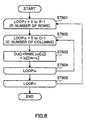
reference to FIG.8. FIG.8 is a flow chart showing
processing of writing to output memory 104 by the address
calculation apparatus of the MIL apparatus according to
Embodiment 4 of the present invention.
-
In ST601, supposing r=0 first, processing up to
ST605, which will be described later, is repeated and
the process ends when r>R-1 is satisfied. Here, R is
the number of rows (here 20).
-
In ST602, supposing c=0 first, processing up to
ST604, which will be described later, is repeated and
the process moves on to ST605 only when C>C-1 is satisfied.
Here, C is the number of rows (here 4).
-
In ST603, the address of output data to which input
data [c+C×r] is to be written is calculated as shown in
the following expression:
r×R+Mil_col[c]
-
Furthermore, input data [c+C×r] is written at the
addresses calculated according to expression (12) in
output memory 104.
-
In ST604, after 1 is added to the value of c, the
process moves on to ST602. In ST605, after 1 is added
to the value of r, the process moves on to ST601.
-
Thus, when inter-frame interleave is performed,
this embodiment stores only column patterns developed
from a MIL expression of stage 1 included in the MIL
expression to be used, further calculates the addresses
of output data to be written for input data and writes
input data at the calculated addresses, and therefore
can implement MIL processing with a small amount of
memory.
(Embodiment 5)
-
Embodiment 5 implements a De-MIL (De-Multistage
InterLeave) apparatus that restores the original
sequence of data whose sequence has been rearranged by
MIL processing. The De-MIL apparatus according to this
embodiment can be implemented with the same
configuration as that of Embodiment 1 (FIG.3).
Hereinafter only differences of the De-MIL apparatus
according to this embodiment from Embodiment 1 will be
explained with reference to FIG.3. In this embodiment,
a case where the original sequence of data whose sequence
has been rearranged according to the MIL expression shown
in expression (1) is restored will be explained as an
example.
-
In FIG.3, input memory 101 stores 20 input data
items In[x] (x=0 to 19) whose sequence has been
rearranged. Row pattern memory 102 stores the row
pattern shown in expression (6). Column pattern memory
103 stores the column pattern shown in expression (7).
Output memory 104 stores 20 output data items Out[y] (y=0
to 19) with the original sequence of input data restored.
-
Address calculation apparatus 105 calculates the
address of input data to be written to the output data
and writes the input data read from input memory 101 based
on the calculated input address to output memory 104 as
the output data. Here, processing of writing to output
memory 104 by address calculation apparatus 105 will be
explained with reference to FIG.9. FIG. 9 is a flow chart
showing processing of writing to output memory 104 by
address calculation apparatus 105 in the De-MIL
apparatus according to Embodiment 5 of the present
invention.
-
In ST701, supposing r=0 first, processing up to
ST705, which will be described later, is repeated and
the processing ends when r>R-1 is satisfied. Here, R is
the number of rows (here 5).
-
In ST702, supposing c=0 first, processing up to
ST704, which will be described later, is repeated and
the process moves on to ST705 only when c>C-1 is satisfied.
Here, C is the number of columns (here 4).
-
In ST703, the address of input data to be written
to output data [C×r+c] is calculated as shown in the
following expression:
Mil_row[r]+R×Mil_col[c]
-
Furthermore, in input memory 101, the input data
stored at the address calculated according to expression
(13) is read and written to output memory 104 as output
data [C×r+c].
-
In ST704, after 1 is added to the value of c, the
process moves on to ST702. In ST705, after 1 is added
to the value of r, the process moves on to ST701.
-
As shown above, this embodiment stores a pattern
developed from a MIL expression of stage 1 included in
the MIL expression to be used, calculates the address
of input data to be written for each output data item
using the stored pattern and writes the input data stored
at the calculated addresses to the output data
sequentially, and therefore can implement De-MIL
processing with a small amount of memory.
(Embodiment 6)
-
Embodiment 6 implements De-MIL processing by
calculating addresses of output data to be written to
input data in Embodiment 5 and writing the input data
at the calculated addresses in the output memory.
-
What this embodiment differs from Embodiment 5 is
processing of writing to output memory 104 by the address
calculation apparatus. Furthermore, this embodiment
differs from Embodiment 5 in row patterns stored in row
pattern memory 102 and column patterns stored in column
pattern memory 103. The components of this embodiment
with the same configuration as that of Embodiment 5 will
be explained with the same reference numerals assigned.
In this embodiment, as in the case of Embodiment 5, the
case where the original sequence of data whose sequence
has been rearranged according to the MIL expression shown
in expression (1) is restored will be explained as an
example.
-
First, row pattern memory 102 stores row pattern
Mil_row[r] shown in expression (3) and column pattern
memory 103 stores column pattern Mil_col[c] shown in
expression (4).
-
Furthermore, the address calculation apparatus
calculates the addresses of output data to be written
for the input data and writes the input data at the
calculated addresses in output memory 104. Here,
processing of writing to output memory 104 by the address
calculation apparatus will be explained with reference
to FIG.10. FIG.10 is a flow chart showing processing of
writing to output memory 104 by the address calculation
apparatus of the De-MIL apparatus according to
Embodiment 6 of the present invention.
-
In ST801, supposing c=0 first, processing up to
ST805, which will be described later, is repeated and
the process ends when c>C-1 is satisfied. Here, C is
the number of columns (here 4).
-
In ST802, supposing r=0 first, processing up to
ST804, which will be described later, is repeated and
the process moves on to ST805 only when r>R-1 is satisfied.
Here, R is the number of rows (here 5).
-
In ST803, the address of output data to which input
data [r+c×R] is to be written is calculated as shown in
the following expression:
C×Mil_row[r]+Mil_col[c]
-
Furthermore, input data [r+c×R] is written at the
address calculated according to expression (14) in
output memory 104.
-
In ST804, after 1 is added to the value of r, the
process moves on to ST802. In ST805, after 1 is added
to the value of c, the process moves on to ST801.
-
As shown above, this embodiment stores a pattern
developed from a MIL expression of stage 1 included in
the MIL expression to be used, calculates the address
of output memory to be written for each input data item
using the stored pattern and writes the input data at
the calculated address, and therefore can implement
De-MIL processing with a small amount of memory.
(Embodiment 7)
-
Embodiment 7 implements De-MIL processing by
writing data in output memory using addresses calculated
using only a column pattern when the original sequence
of data is restored between frames in Embodiment 5, that
is, when a column pattern is a simple incremental value.
-
What this embodiment differs from Embodiment 5
first is processing of writing to output memory by the
address calculation apparatus. Furthermore, in this
embodiment, row pattern memory 102 in Embodiment 5 is
excluded. In this embodiment, only differences from
Embodiment 5 will be explained below. The components of
this embodiment with the same configuration as that of
Embodiment 5 will be explained with the same reference
numerals assigned. In this embodiment, the case where
the original sequence of data whose sequence has been
rearranged according to the MIL expression shown in
expression (9) is restored will be explained as an
example.
-
First, column pattern memory 103 stores column
pattern Mil_col[c] shown in expression (10) created from
MIL expression (4[2×2]) of stage 1 in expression (9).
-
Furthermore, the address calculation apparatus
calculates addresses of input data to be written to
output data and writes the input data read from input
memory 101 based on the calculated input addresses to
output memory 104 as output data. Here, processing of
writing to output memory 104 by the address calculation
apparatus will be explained with reference to FIG.11.
FIG.11 is a flow chart showing processing of writing to
output memory 104 by the address calculation apparatus
of the De-MIL apparatus according to Embodiment 7 of the
present invention.
-
In ST901, supposing r=0 first, processing up to
ST905, which will be described later, is repeated and
the process ends when r>R-1 is satisfied. Here, R is
the number of rows (here 20).
-
In ST902, supposing c=0 first, processing up to
ST904, which will be described later, is repeated and
the process moves on to ST905 only when c>C-1 is satisfied.
Here, C is the number of columns (here 4).
-
In ST903, the address of input data to be written
to output data [C×r+c] is calculated as shown in the
following expression:
R×Mil_col[c]+r
-
Furthermore, in input memory 101, input data stored
at addresses calculated according to expression (15) is
read and written in output memory 104 as output data
[C×r+c].
-
In ST904, after 1 is added to the value of c, the
process moves on to ST902. In ST905, after 1 is added
to the value of r, the process moves on to ST901.
-
As shown above, when the original sequence of data
is restored between frames, this embodiment only stores
a column pattern developed from a MIL expression of stage
1 included in the MIL expression to be used, calculates
addresses of input data to be written for each output
data item using the stored pattern and writes the input
data stored at the calculated addresses to the output
data sequentially, and therefore can implement De-MIL
processing with a small amount of memory.
(Embodiment 8)
-
Embodiment 8 implements De-MIL processing by
calculating the addresses of output data to be written
for each input data item using only a column pattern and
writing each input data item at the calculated address
in output memory when the original sequence of data is
restored between frames in Embodiment 6, that is, when
a column pattern is a simple incremental value.
-
What this embodiment differs from Embodiment 6 is
processing of writing to output memory 104 by the address
calculation apparatus. Furthermore, in this embodiment,
row pattern memory 102 in Embodiment 6 is excluded. In
this embodiment, only differences from Embodiment 6 will
be explained below. The components of this embodiment
with the same configuration as that of Embodiment 1 will
be explained with the same reference numerals assigned.
In this embodiment, the case where the original sequence
of data whose sequence has been rearranged according to
the MIL expression shown in expression (9) is restored
will be explained as an example.
-
First, column pattern memory 103 stores column
pattern Mil_col[c] shown in expression (10).
Furthermore, the address calculation apparatus
calculates the addresses of output data to be written
for the input data and writes the input data at the
addresses calculated in output memory 104. Here,
processing of writing to output memory 104 by the address
calculation apparatus will be explained with reference
to FIG.12. FIG.12 is a flow chart showing processing of
writing to output memory 104 by the address calculation
apparatus of the De-MIL apparatus according to
Embodiment 8 of the present invention.
-
In ST1001, supposing c=0 first, processing up to
ST1005, which will be described later, is repeated and
the process ends when c>C-1 is satisfied. Here, C is
the number of columns (here 4).
-
In ST1002, supposing r=0 first, processing up to
ST1004, which will be described later, is repeated and
the process moves on to ST1005 only when r>R-1 is
satisfied. Here, R is the number of rows (here 20).
-
In ST1003, the address of output data to which input
data [r+c×R] is to be written is calculated as shown in
the following expression:
r+R×Mil_col[c]
-
Furthermore, input data [r+c×R] is written at the
address calculated according to expression (16) in
output memory 104.
-
In ST1004, after 1 is added to the value of r, the
process moves on to ST1002. In ST1005, after 1 is added
to the value of c, the process moves on to ST1001.
-
As shown above, when the original sequence of data
is restored between frames, this embodiment only stores
a column pattern developed from a MIL expression of stage
1 included in the MIL expression to be used, calculates
the address in output memory in which the data is to be
written using the stored pattern and writes the input
data at the calculated address, and therefore can
implement De-MIL processing with a small amount of
memory.
(Embodiment 9)
-
Embodiment 9 implements a coding apparatus
comprising any one of the MIL apparatuses according to
Embodiment 1 to Embodiment 4, or a MIL apparatus that
combines Embodiment 1 to Embodiment 4, a transmission
data coding apparatus and a transmission data length
adjusting apparatus.
-
The coding apparatus according to this embodiment
will be explained with reference to FIG.13. FIG.13 is
a block diagram showing a configuration of the coding
apparatus according to Embodiment 9 of the present
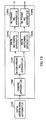
invention. As shown in FIG.13, the coding apparatus
according to this embodiment is mainly configured by data
generation apparatus 1101 such as a microphone, coding
apparatus 1102 that performs CRC coding and error
correction coding, inter-frame MIL apparatus 1103 that
performs MIL between frames, rate matching apparatus
1104a and rate matching apparatus 1104b that perform
transmission data repetition/puncturing and in-frame
MIL apparatus 1105a and in-frame MIL apparatus 1105b that
perform MIL inside a frame.
-
Data generation apparatus 1101 generates data
corresponding to a few frames (here 2 frames). Coding
apparatus 1102 performs CRC coding and error correction
coding on the 2-frame data generated.
-
Inter-frame MIL apparatus 1103 performs inter-frame
MIL processing on the coded 2-frame data. As the
inter-frame MIL apparatus, for example, the MIL
apparatus according to Embodiment 3 or Embodiment 4 above
can be used.
-
Rate matching apparatus 1104a and rate matching
apparatus 1104b each perform repetition/puncturing
processing on data of each frame subjected to inter-frame
MIL processing.
-
In-frame MIL apparatus 1105a and in-frame MIL
apparatus 1105b each perform in-frame MIL on data of each
frame subjected to repetition/puncturing processing.
As the in-frame MIL apparatus, for example, the MIL
apparatus according to Embodiment 1 or Embodiment 2 above
can be used.
-
As shown above, this embodiment can drastically
reduce the amount of memory required for the inter-frame
MIL apparatuses and in-frame MIL apparatuses, and
therefore can significantly reduce the circuit scale of
the coding apparatus.
(Embodiment 10)
-
Embodiment 10 implements a decoding apparatus
comprising any one of the De-MIL apparatuses according
to Embodiment 5 to Embodiment 8, or a De-MIL apparatus
that combines Embodiment 5 to Embodiment 8, a reception
data decoding apparatus and a reception data length
adjusting apparatus.
-
The decoding apparatus according to this
embodiment will be explained with reference to FIG.14.
FIG.14 is a block diagram showing a configuration of the
decoding apparatus according to Embodiment 10. As shown
in FIG.14, the decoding apparatus according to this
embodiment is mainly configured by in-frame De-MIL
apparatus 1201a and De-MIL apparatus 1201b that perform
De-MIL inside a frame, rate matching apparatus 1202a and
rate matching apparatus 1202b that perform reception
data repetition/puncturing, inter-frame De-MIL
apparatus 1203 that performs De-MIL between frames,
decoding apparatus 1204 that performs CRC decoding and
error correction decoding and data output apparatus
1205.
-
In-frame De-MIL apparatus 1201a and in-frame
De-MIL apparatus 1201b each perform in-frame De-MIL on
reception data corresponding to a few frames (here 2
frames) . As the in-frame De-MIL apparatus, for example,
the De-MIL apparatus according to Embodiment 5 or
Embodiment 6 above can be used.
-
Rate matching apparatus 1202a and rate matching
apparatus 1202b each perform rate matching processing
on reception data subjected to De-MIL processing for each
frame.
-
Inter-frame De-MIL apparatus 1203 performs
inter-frame MIL processing on the 2-frame reception data
subjected to rate matching processing. As the inter-frame
De-MIL apparatus, for example, the De-MIL
apparatus according to Embodiment 7 or Embodiment 8 above
can be used.
-
Decoding apparatus 1204 performs error correction
decoding and CRC decoding on the reception data subjected
to inter-frame De-Mil processing. Data output
apparatus 1205 performs output processing on the
reception data subjected to error correction decoding
and CRC decoding.
-
As shown above, this embodiment can drastically
reduce the amount of memory required for the inter-frame
De-MIL apparatuses and in-frame De-MIL apparatuses, and
therefore can significantly reduce the circuit scale of
the coding apparatus.
-
This embodiment describes the case where in-frame
De-MIL processing, rate matching processing and
inter-frame De-MIL processing are carried out
sequentially as an example, but it is also possible to
carry out in-frame De-MIL processing, inter-frame De-MIL
processing and rate matching processing sequentially.
(Embodiment 11)
-
Embodiment 11 implements a mobile station
apparatus using the coding apparatus in Embodiment 9 and
decoding apparatus in Embodiment 10. The mobile station
apparatus according to this embodiment will be explained
with reference to FIG.15. FIG.15 is a block diagram
showing a configuration of the mobile station apparatus
according to Embodiment 11 of the present invention.
-
As shown in FIG.15, the mobile station apparatus
according to this embodiment is mainly configured by
transmission/reception apparatus 1301 that performs
transmission/reception processing,
synchronization/demodulation apparatus 1302 that
performs synchronization and demodulation processing of
reception data, decoding processing apparatus 1303
according to Embodiment 10 above, data output apparatus
1304 that outputs data, data generation apparatus 1305
that generates data or captures data such as voice from
the outside, coding processing apparatus 1306 in
Embodiment 9 above and spreading/modulation apparatus
1307 that performs spreading/modulation processing of
transmission data.
-
This embodiment can drastically reduce the amount
of memory required for inter-frame MIL, inter-frame
De-MIL and in-frame MIL and in-frame De-MIL, and
therefore can drastically reduce the circuit scale of
the mobile station apparatus.
-
Furthermore, in the case where the in-frame MIL
apparatus of Embodiment 1 (2) is used as the in-frame
MIL apparatus in coding processing apparatus 1306 and
the in-frame De-MIL apparatus of Embodiment 6 (5) is used
as the in-frame De-MIL apparatus in decoding processing
apparatus 1303, the in-frame MIL apparatus and in-frame
De-MIL apparatus can use common row patterns and column
patterns, making it possible to further reduce the
circuit scale.
(Embodiment 12)
-
Embodiment 12 implements a base station apparatus
using the coding apparatus in Embodiment 9 and decoding
apparatus in Embodiment 10. The base station apparatus
according to this embodiment will be explained with
reference to FIG.16. FIG.16 is a block diagram showing
a configuration of the base station apparatus according
to Embodiment 12 of the present invention.
-
As shown in FIG.16, the base station apparatus
according to this embodiment is mainly configured by
transmission/reception apparatus 1401 that performs
transmission/reception processing, demodulation
apparatus 1402 that performs demodulation processing of
reception data, decoding processing apparatus 1403 in
Embodiment 10 above, data output apparatus 1404 that
outputs data, data generation apparatus 1405 that
generates data, coding processing apparatus 1406 in
Embodiment 9 above and spreading/modulation apparatus
1407 that performs spreading/modulation processing of
transmission data.
-
As shown above, this embodiment can drastically
reduce the amount of memory required for inter-frame MIL,
inter-frame De-MIL and in-frame MIL and in-frame De-MIL,
and therefore can drastically reduce the circuit
scale of the mobile station apparatus.
-
Furthermore, in the case where the in-frame MIL
apparatus in Embodiment 1 (2) is used as the in-frame
MIL apparatus in coding processing apparatus 1406 and
the in-frame De-MIL apparatus in Embodiment 6 (5) is used
as the in-frame De-MIL apparatus in decoding processing
apparatus 1403, the in-frame MIL apparatus and in-frame
De-MIL apparatus can use common row patterns and column
patterns, making it possible to further reduce the
circuit scale.
-
The above embodiment describes the case where at
least one element of stage 1 of a MIL expression are used,
but the present invention is also applicable to a case
where at least one element of any stage are used.
-
The above embodiment describes the case where when
the sequence of data is rearranged between frames, a
column pattern developed from a MIL expression of stage
1 included in the MIL expression is used, but the present
invention is also applicable to a case where a row pattern
developed from a MIL expression of stage 1 included in
the MIL expression is used.
-
Furthermore, the above embodiment describes the
case where when the sequence of data is rearranged
between frames, a MIL pattern developed from a MIL
expression of stage 1 included in the MIL expression is
used, but the present invention is also applicable to
a case where when one MIL expression included in a MIL
expression is lower than the other MIL expression in the
MIL expression by at least one stage, the MIL pattern
developed from the other MIL expression is used.
1 ○ The interleave apparatus according to the first
embodiment of the present invention has a configuration
comprising a conversion series creating section for
creating at least one sequence conversion series using
elements included in a sequence conversion rule
expression specified for every input data item and a
sequence changing section for changing the sequence of
the input data using the created sequence conversion
series.
-
This configuration makes it possible to create a
sequence conversion series (MIL pattern) using elements
in the sequence conversion rule (MIL expression), for
example, a row pattern expression or column pattern
expression created from each element of stage 1 and
change the sequence of the input data using the created
sequence conversion series, and therefore allows MIL
processing to be performed with a reduced amount of
memory required.
2 ○ The interleave apparatus according to the second
embodiment of the present invention has a configuration
with the sequence changing section of the first
embodiment further comprising a first sequence
calculating section for calculating the changed sequence
of the input data and changing the sequence of the input
data according to the calculated sequence.
-
This configuration ensures that the sequence of the
input data is changed by calculating the sequence after
the change of the sequence of the input data using the
created sequence conversion series.
3 ○ The interleave apparatus according to the third
embodiment of the present invention has a configuration
with the sequence changing section of the first
embodiment further comprising a second sequence
calculating section for calculating the sequence of
input data to be placed in this input data and changing
the sequence of the input data according to the
calculated sequence.
-
This configuration ensures that the sequence of the
input data is changed by calculating the sequence of the
input data to be placed in the input data after the change
of the sequence using the created sequence conversion
series.
4 ○ The interleave apparatus according to the fourth
embodiment of the present invention has a configuration
with the conversion series creating section of any one
of the first embodiment to third embodiment creating a
sequence conversion series, when one element included
in the sequence conversion rule expression is lower than
the other element by at least 1 stage, using the other
element.
-
This configuration allows the amount of required
memory to be further reduced by creating a sequence
conversion series using only a column pattern expression
when, for example, only the column pattern expression
is included in the sequence conversion rule expression.
5 ○ The interleave apparatus according to the fifth
embodiment of the present invention has a configuration
with the sequence changing section of the first
embodiment to fourth embodiment changing the sequence
of input data whose sequence has been changed according
the sequence conversion rule expression.
-
This configuration allows the original sequence of
the input data whose sequence has been changed according
to this sequence conversion rule expression to be
restored by using the sequence conversion series created
using the same sequence conversion rule expression.
6 ○ The communication terminal apparatus according to the
sixth embodiment of the present invention comprises an
interleave apparatus that has a configuration comprising
a conversion series creating section for creating at
least one sequence conversion series using elements
included in a sequence conversion rule expression
specified for every input data item and sequence changing
section for changing the sequence of the input data using
the created sequence conversion series.
-
This configuration provides a communication
terminal apparatus with a reduced circuit scale by
including an interleave apparatus that reduces required
memory.
7 ○ The base station apparatus according to the seventh
embodiment of the present invention comprises an
interleave apparatus that has a configuration comprising
a conversion series creating section for creating at
least one sequence conversion series using elements
included in a sequence conversion rule expression
specified for every input data item and a sequence
changing section for changing the sequence of the input
data using the created sequence conversion series.
-
This configuration provides a base station
apparatus with a reduced circuit scale by including an
interleave apparatus that reduces required memory.
8 ○ The radio communication system according to the eighth
embodiment of the present invention performs
communications between a communication terminal
apparatus equipped with an interleave apparatus and a
base station apparatus equipped with the interleave
apparatus above that has a configuration comprising a
conversion series creating section for creating at least
one sequence conversion series using elements included
in a sequence conversion rule expression specified for
every input data item and a sequence changing section
for changing the sequence of the input data using the
created sequence conversion series.
-
This configuration allows efficient radio
communications to be implemented using the communication
terminal apparatus and base station apparatus with a
reduced circuit scale.
9 ○ The interleave method according to the ninth
embodiment of the present invention comprises a
conversion series creating step of creating at least one
sequence conversion series using elements included in
a sequence conversion rule expression specified for
every input data item and a sequence changing step of
changing the sequence of the input data using the created
sequence conversion series.
-
This method makes it possible to create a sequence
conversion series using elements in the sequence
conversion rule, for example, a row pattern expression
or column pattern expression created from each element
of
stage 1 and change the sequence of the input data using
the created sequence conversion series, and therefore
allows MIL processing to be performed with a reduced
amount of memory required.
The interleave method according to the tenth
embodiment of the present invention comprises a
conversion series creating step of creating at least one
sequence conversion series using elements included in
a sequence conversion rule expression specified for
every input data item and a sequence restoring step of
restoring the sequence of the input data whose sequence
has been changed according to the sequence conversion
rule expression above using the created sequence
conversion series.
-
This method allows the original sequence of input
data whose sequence has been changed according to this
sequence conversion rule expression to be restored by
using the sequence conversion series created using the
same sequence conversion rule expression.
-
As described above, the present invention creates
at least one MIL pattern (sequence conversion series)
using at least one element included in a MIL
expression(sequence conversion rule expression)
stipulated or specified for every input data item and
changes the sequence of the input data using the created
MIL pattern, and therefore can provide an interleave
apparatus capable of reducing the amount of memory
required.
-
This application is based on the Japanese Patent
Application No.HEI 11-164055 filed on June 10, 1999,
entire content of which is expressly incorporated by
reference herein.
Industrial Applicability
-
The present invention is preferable to be used in
a field of a coding/decoding processing apparatus and
coding/decoding processing method in a CDMA mobile
communication.