EP1111965A2 - Convection device of microwave oven - Google Patents
Convection device of microwave oven Download PDFInfo
- Publication number
- EP1111965A2 EP1111965A2 EP00403400A EP00403400A EP1111965A2 EP 1111965 A2 EP1111965 A2 EP 1111965A2 EP 00403400 A EP00403400 A EP 00403400A EP 00403400 A EP00403400 A EP 00403400A EP 1111965 A2 EP1111965 A2 EP 1111965A2
- Authority
- EP
- European Patent Office
- Prior art keywords
- cooking chamber
- microwave oven
- air
- fan
- heater
- Prior art date
- Legal status (The legal status is an assumption and is not a legal conclusion. Google has not performed a legal analysis and makes no representation as to the accuracy of the status listed.)
- Granted
Links
Images


Classifications
-
- F—MECHANICAL ENGINEERING; LIGHTING; HEATING; WEAPONS; BLASTING
- F24—HEATING; RANGES; VENTILATING
- F24C—DOMESTIC STOVES OR RANGES ; DETAILS OF DOMESTIC STOVES OR RANGES, OF GENERAL APPLICATION
- F24C7/00—Stoves or ranges heated by electric energy
- F24C7/02—Stoves or ranges heated by electric energy using microwaves
-
- H—ELECTRICITY
- H05—ELECTRIC TECHNIQUES NOT OTHERWISE PROVIDED FOR
- H05B—ELECTRIC HEATING; ELECTRIC LIGHT SOURCES NOT OTHERWISE PROVIDED FOR; CIRCUIT ARRANGEMENTS FOR ELECTRIC LIGHT SOURCES, IN GENERAL
- H05B6/00—Heating by electric, magnetic or electromagnetic fields
- H05B6/64—Heating using microwaves
- H05B6/647—Aspects related to microwave heating combined with other heating techniques
- H05B6/6473—Aspects related to microwave heating combined with other heating techniques combined with convection heating
Definitions
- the present invention relates to a microwave oven including a heater, in particular to a convection device of a microwave oven which is capable of providing the heat generated from a heater uniformly inside of a cooking chamber.
- a microwave oven heats a heating object by using microwave.
- the heater is installed as the other heating source besides the microwave, and the heat generated by the heater is used for heating the heating object.
- FIG.1 illustrates the conventional microwave oven including the heater as the heating source besides the microwave.
- a heater chamber 4 is formed on the external upper portion of a cooking chamber 2, and heaters 6a, 6b are installed inside of the heater chamber 4.
- a fan 10 is installed on the center portion of the heater chamber 4, the fan 10 is rotated by a motor M installed on the upper portion of the heater chamber 4.
- a sucking portion 8 and discharging portion 9a, 9b are. formed on the upper surface of the cooking chamber 2 corresponding to the bottom surface of the heater chamber 4 in order to circulate air by the fan 10.
- the sucking portion 8 is formed on the lower center portion of the fan 10 in order to suck the air inside of the cooking chamber 2
- the discharging portion 9a, 9b are formed on the portion corresponding to the lower edge of the fan 10 in order to provide the air sucked through the sucking portion 8 to the inside of the cooking chamber 2.
- the fan 10 when the heating is performed by the heater 6a, 6b, the fan 10 operates at the same time with the heat generation of the heater 6a, 6b to which power has been applied.
- the air sucked from the cooking chamber 2 by the sucking portion 8 according to the operation of the fan 10 is heated while circulating inside of the heater chamber 4 and passing through the heater 6a, 6b, and is flowed into the cooking chamber 2 through the discharge portion 9a, 9b.
- the heated-air circulating inside of the heater chamber 4 and cooking chamber 2 can not circulate sufficiently inside of the cooking chamber 2 while flowing through the sucking portion 8 on the center portion and the discharge portion 9a, 9b on the edge.
- the circulation of the heated-air is even on the upper center portion of the cooking chamber 2 adjacent to the fan 10, but the circulation of the heated-air on the lower portion such as a corner portion is not even.
- the air-flow is generated by sucking the air on the center portion and using the centrifugal force of the fan 10 downwardly fixed, the appropriate air-flow for transmitting the heat to the overall cooking chamber 2 can not be generated. Accordingly, the foodstuff can not be uniformly heated because the conventional convection heating type microwave oven can not uniformly distribute the heat.
- the air provided through the discharge portion 9a, 9b is the heated-air heated through the heat-exchange with the heater 6a, 6b, when the heated-air is provided to the inside of the cooking chamber 2, the heated-air contacts first with a side surface of the cooking chamber 2, accordingly the temperature of the heated-air lowers due to the heat loss.
- the heat transmission efficiency with the foodstuff lowers because the heat of the air is taken away to the side wall surface by contacting it first.
- the object of the present invention is to provide a convection device of a microwave oven which is capable of transmitting uniformly the heat generated from a heater to each part inside of a cooking chamber.
- the other object of the present invention is to provide the convection device of the microwave oven which is capable of providing selectively the heat generated from the heater to a predetermined portion inside of the cooking chamber.
- the convection device of the present invention comprises a heater chamber installed on the side wall surface of the cooking chamber, a fan housing installed inside of the heater chamber so as to be rotational within a predetermined rotation range including an inlet hole where the air inside of the heater chamber flows into and a discharging hole for providing the air into the cooking chamber, and a fan installed inner side surface of the fan housing for generating the air-flow provided inside of the cooking chamber through a discharging hole.
- FIG.1 is a sectional view illustrating the construction of a conventional convection device.
- FIG.2 is a sectional view illustrating the construction of a convection device according to the present invention.
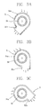
- FIG.3A is a sectional view illustrating the operation of a fan housing according to the present invention.
- FIG.3B is a sectional view illustrating the operation of a fan housing according to the other embodiment of the present invention.
- FIG.3C is a sectional view illustrating the operation of a fan housing according to the another embodiment of the present invention.
- FIG.4 is a perspective view illustrating the construction of a fan housing according to the present invention.
- a heater chamber 30 is formed on the out-side surface of a cooking chamber 20 of the microwave oven according to the present invention.
- a fan 32 and a heater 35 as a heating source are installed inside of the heater chamber 30.
- the heat generated from the heater 35 is provided inside of the cooking chamber 20 through the airflow by the fan 32. It is possible to construct a pair of straight shape heaters or one U-shaped bending heater as the heater 35.
- An inlet/outlet portion 42 for sucking or discharging the air to the cooking chamber 20 is formed on the lower side surface of the heater chamber 30 installed on the upper surface of the cooking chamber 20, the inlet/outlet portion 42 is generally constructed as a mesh-net or a plate having a plurality of air through hole.
- the inlet/outlet portion 42 is constructed with a discharging portion 42a for providing downwardly the high temperature air to the cooking chamber 20, and a sucking portion 42b for sucking the low temperature air performed the heat transmission inside of the cooking chamber 20 to the inside of the heater chamber 30.
- the inlet/outlet portion 42 connects the inside of the heater chamber 30 to the cooking chamber 20 to be ventilated.
- the fan housing 31 is installed so as to be rotational within a predetermined rotation range.
- the rotating angle range of the fan housing 31 can be controlled according to type or amount of the foodstuff. Accordingly, a discharging hole 31b of the fan housing 31 rotates to the left or center or right directions inside of the cooking chamber 20. Likewise, it is possible to provide uniformly the heated-air to the each portion inside of the cooking chamber 20 by installing the fan housing 31 to be rotational.
- a rack gear unit 33 is formed on the outer side of the fan housing 31.
- a rack gear 33a of the rack gear unit 33 rotates within a predetermined rotation range according to direct or reverse rotation of an operating gear 34 by meshing with an operating gear 34.
- the operating gear 34 is connected to an output shaft of a stepping motor Ms that can rotate to the direct or reverse rotation
- an inlet hole 31a where the outer air flows into the fan housing is formed on the upper portion of the fan housing 31, and a discharging hole 31b for discharging the air inside of the cooking chamber 20 is formed on the lower portion of the fan housing 31.
- the air flowed into the fan housing 31 through the inlet hole 31 a is the heated-air which made of the heat exchange between the heater 35.
- a non-described reference numeral M of FIG.4 is an operating motor for rotating the fan 32 according to the present invention. And, in the present invention, a radial-flow flow fan is used as the fan 32, but the present invention is not limited by that.
- the heater 35 heats and at the same time the fan 32 rotates and generates the airflow.
- the stepping motor Ms performs the direct and reverse rotation within the predetermined rotation range.
- the air flow generated according to the rotation of the fan 32 is discharged through the discharging hole 31b formed on the lower portion of the fan housing 31, after passing the inlet hole 31a formed on the upper portion of the fan housing 31, passes through the inlet/outlet portion 42, and is provided inside of the cooking chamber 20.
- the operating gear 34 repeats the direct or reverse rotation within the predetermined rotation range by operating of the stepping motor Ms, as depicted in FIG.3A, 3B, 3C, the fan housing 31 is rotated repeatedly within the predetermined rotation range. And the heated-air flowed into the cooking chamber 20 can be provided uniformly to the each portion of the cooking chamber 20, accordingly the uniform temperature distribution is performed.
- the heated-air flowed into the cooking chamber 20 by the fan housing 31 performs the heat exchange while contacting with the foodstuff F, the low temperature air which is altered from the heated-air flows again into the heat chamber 30 through the inlet/outlet portion 42 after passing the other wall surface of the cooking chamber 20.
- the low temperature air flowed into the heater chamber 30 is re-heated by the heater 35, and is provided into the cooking chamber 20 through the fan housing 31.
- the convection device of the microwave oven according to the present invention it is possible to provide concentrically the heated-air to the selected portion inside of the cooking chamber 20 by using the fan housing 31. And, it is possible also to adapt the convection device of the microwave oven according to the present invention to a general cooking oven for cooking oven for cooking the foodstuff.
- the convection device of the microwave oven according to the present invention is capable of providing uniformly the heated-air inside of the cooking chamber 20 by rotating the fan housing, and providing concentrically the heated-air to the predetermined portion, accordingly the microwave oven according to the present invention is convenient to use.
- the convection device of the microwave oven according to the present invention is capable of controlling the rotating range of the fan housing 31 in accordance with the type or amount of the foodstuff, accordingly the foodstuff can be cooked uniformly and the cooking speed can be improved.
- the heated-air provided into the cooking chamber 20 through the fan housing 31 contacts first with the foodstuff, and is sucked through the side wall of the cooking chamber 20, accordingly the heat loss which is transmitted to the outside of the cooking chamber 20 can be minimized.
- the efficiency of the energy consumption and quality of the dish cooked by using the convection device of the microwave oven according to the present invention can be improved by using the heat efficiently and reducing the cooking time.
Abstract
Description
- The present invention relates to a microwave oven including a heater, in particular to a convection device of a microwave oven which is capable of providing the heat generated from a heater uniformly inside of a cooking chamber.
- A microwave oven heats a heating object by using microwave. In recent years, in order to add more various heating function to the microwave oven, the heater is installed as the other heating source besides the microwave, and the heat generated by the heater is used for heating the heating object.
- FIG.1 illustrates the conventional microwave oven including the heater as the heating source besides the microwave. As depicted in FIG.1, a heater chamber 4 is formed on the external upper portion of a
cooking chamber 2, andheaters - A
fan 10 is installed on the center portion of the heater chamber 4, thefan 10 is rotated by a motor M installed on the upper portion of the heater chamber 4. A suckingportion 8 and dischargingportion cooking chamber 2 corresponding to the bottom surface of the heater chamber 4 in order to circulate air by thefan 10. - In more detail, the sucking
portion 8 is formed on the lower center portion of thefan 10 in order to suck the air inside of thecooking chamber 2, and thedischarging portion fan 10 in order to provide the air sucked through the suckingportion 8 to the inside of thecooking chamber 2. - In the conventional microwave oven, when the heating is performed by the
heater fan 10 operates at the same time with the heat generation of theheater cooking chamber 2 by the suckingportion 8 according to the operation of thefan 10 is heated while circulating inside of the heater chamber 4 and passing through theheater cooking chamber 2 through thedischarge portion - However, the conventional convection heating type microwave oven has below problems.
- In the heat convection, the heated-air circulating inside of the heater chamber 4 and
cooking chamber 2 can not circulate sufficiently inside of thecooking chamber 2 while flowing through the suckingportion 8 on the center portion and thedischarge portion cooking chamber 2 adjacent to thefan 10, but the circulation of the heated-air on the lower portion such as a corner portion is not even. - In the heat convection of the convection heating type microwave oven, because the air-flow is generated by sucking the air on the center portion and using the centrifugal force of the
fan 10 downwardly fixed, the appropriate air-flow for transmitting the heat to theoverall cooking chamber 2 can not be generated. Accordingly, the foodstuff can not be uniformly heated because the conventional convection heating type microwave oven can not uniformly distribute the heat. - And, the air provided through the
discharge portion heater cooking chamber 2, the heated-air contacts first with a side surface of thecooking chamber 2, accordingly the temperature of the heated-air lowers due to the heat loss. In other words, the heat transmission efficiency with the foodstuff lowers because the heat of the air is taken away to the side wall surface by contacting it first. - The object of the present invention is to provide a convection device of a microwave oven which is capable of transmitting uniformly the heat generated from a heater to each part inside of a cooking chamber.
- The other object of the present invention is to provide the convection device of the microwave oven which is capable of providing selectively the heat generated from the heater to a predetermined portion inside of the cooking chamber.
- In order to achieve the objects, the convection device of the present invention comprises a heater chamber installed on the side wall surface of the cooking chamber, a fan housing installed inside of the heater chamber so as to be rotational within a predetermined rotation range including an inlet hole where the air inside of the heater chamber flows into and a discharging hole for providing the air into the cooking chamber, and a fan installed inner side surface of the fan housing for generating the air-flow provided inside of the cooking chamber through a discharging hole.
- FIG.1 is a sectional view illustrating the construction of a conventional convection device.
- FIG.2 is a sectional view illustrating the construction of a convection device according to the present invention.
- FIG.3A is a sectional view illustrating the operation of a fan housing according to the present invention.
- FIG.3B is a sectional view illustrating the operation of a fan housing according to the other embodiment of the present invention.
- FIG.3C is a sectional view illustrating the operation of a fan housing according to the another embodiment of the present invention.
- FIG.4 is a perspective view illustrating the construction of a fan housing according to the present invention.
- Hereinafter, the embodiment of a convection device of a microwave oven according to the present invention will now be described with reference to accompanying drawings.
- As depicted in FIG.2, a
heater chamber 30 is formed on the out-side surface of acooking chamber 20 of the microwave oven according to the present invention. - A
fan 32 and aheater 35 as a heating source are installed inside of theheater chamber 30. The heat generated from theheater 35 is provided inside of thecooking chamber 20 through the airflow by thefan 32. It is possible to construct a pair of straight shape heaters or one U-shaped bending heater as theheater 35. - An inlet/
outlet portion 42 for sucking or discharging the air to thecooking chamber 20 is formed on the lower side surface of theheater chamber 30 installed on the upper surface of thecooking chamber 20, the inlet/outlet portion 42 is generally constructed as a mesh-net or a plate having a plurality of air through hole. - As depicted in FIG.2, when the
fan housing 31 is downwardly placed, the inlet/outlet portion 42 is constructed with adischarging portion 42a for providing downwardly the high temperature air to thecooking chamber 20, and a suckingportion 42b for sucking the low temperature air performed the heat transmission inside of thecooking chamber 20 to the inside of theheater chamber 30. - The inlet/
outlet portion 42 connects the inside of theheater chamber 30 to thecooking chamber 20 to be ventilated. - As depicted in FIG.3A, 3B, 3C, the
fan housing 31 is installed so as to be rotational within a predetermined rotation range. In addition, the rotating angle range of thefan housing 31 can be controlled according to type or amount of the foodstuff. Accordingly, adischarging hole 31b of thefan housing 31 rotates to the left or center or right directions inside of thecooking chamber 20. Likewise, it is possible to provide uniformly the heated-air to the each portion inside of thecooking chamber 20 by installing thefan housing 31 to be rotational. - The structure of the fan housing 31 according to the present invention will now be described.
- As depicted in FIG.4, a rack gear unit 33 is formed on the outer side of the
fan housing 31. As depicted in FIG.3, arack gear 33a of the rack gear unit 33 rotates within a predetermined rotation range according to direct or reverse rotation of anoperating gear 34 by meshing with anoperating gear 34. Theoperating gear 34 is connected to an output shaft of a stepping motor Ms that can rotate to the direct or reverse rotation - And, an
inlet hole 31a where the outer air flows into the fan housing is formed on the upper portion of thefan housing 31, and adischarging hole 31b for discharging the air inside of thecooking chamber 20 is formed on the lower portion of thefan housing 31. The air flowed into thefan housing 31 through theinlet hole 31 a is the heated-air which made of the heat exchange between theheater 35. - A non-described reference numeral M of FIG.4 is an operating motor for rotating the
fan 32 according to the present invention. And, in the present invention, a radial-flow flow fan is used as thefan 32, but the present invention is not limited by that. - Hereinafter, the overall operating relation of the convection device according to the present invention will now be described.
- When the power is applied to the
heater 35, theheater 35 heats and at the same time thefan 32 rotates and generates the airflow. In addition, when the power is applied to the stepping motor Ms, the stepping motor Ms performs the direct and reverse rotation within the predetermined rotation range. - The air flow generated according to the rotation of the
fan 32 is discharged through thedischarging hole 31b formed on the lower portion of thefan housing 31, after passing theinlet hole 31a formed on the upper portion of thefan housing 31, passes through the inlet/outlet portion 42, and is provided inside of thecooking chamber 20. - In addition, at the same time the
operating gear 34 repeats the direct or reverse rotation within the predetermined rotation range by operating of the stepping motor Ms, as depicted in FIG.3A, 3B, 3C, thefan housing 31 is rotated repeatedly within the predetermined rotation range. And the heated-air flowed into thecooking chamber 20 can be provided uniformly to the each portion of thecooking chamber 20, accordingly the uniform temperature distribution is performed. - And, the heated-air flowed into the
cooking chamber 20 by thefan housing 31 performs the heat exchange while contacting with the foodstuff F, the low temperature air which is altered from the heated-air flows again into theheat chamber 30 through the inlet/outlet portion 42 after passing the other wall surface of thecooking chamber 20. - The low temperature air flowed into the
heater chamber 30 is re-heated by theheater 35, and is provided into thecooking chamber 20 through thefan housing 31. - In the other embodiment of the present invention, it is possible to provide concentrically the heated-air to the selected portion inside of the
cooking chamber 20 by using thefan housing 31. And, it is possible also to adapt the convection device of the microwave oven according to the present invention to a general cooking oven for cooking oven for cooking the foodstuff. - As described above, the convection device of the microwave oven according to the present invention is capable of providing uniformly the heated-air inside of the
cooking chamber 20 by rotating the fan housing, and providing concentrically the heated-air to the predetermined portion, accordingly the microwave oven according to the present invention is convenient to use. In addition, the convection device of the microwave oven according to the present invention is capable of controlling the rotating range of thefan housing 31 in accordance with the type or amount of the foodstuff, accordingly the foodstuff can be cooked uniformly and the cooking speed can be improved. - In addition, the heated-air provided into the
cooking chamber 20 through thefan housing 31 contacts first with the foodstuff, and is sucked through the side wall of thecooking chamber 20, accordingly the heat loss which is transmitted to the outside of thecooking chamber 20 can be minimized. In addition, the efficiency of the energy consumption and quality of the dish cooked by using the convection device of the microwave oven according to the present invention can be improved by using the heat efficiently and reducing the cooking time.
Claims (6)
- A convection device of a microwave oven, comprising:a heater chamber (30) formed on the side wall surface of a cooking chamber (20) ;a fan housing (31) installed inside of the heater chamber (30) so as to be rotational within a predetermined rotation range including an inlet hole where the air inside of the heater chamber (30) flows into and a discharging hole (31b) for providing the air into the cooking chamber (20) ; anda fan (32) installed inner side of the fan housing (31) for generating airflow provided into the cooking chamber (20) through the discharging hole (31b).
- The convection device of the microwave oven according to claim 1, wherein the fan (32) is a radial-flow fan.
- The convection device of the microwave oven according to claim 1, wherein a rack gear unit (33) is formed on the outer side surface of the fan housing (31).
- The convection device of the microwave oven according to claim 3, wherein a rack gear (33a) of the rack gears unit (33) is formed to mesh with an operating gear (34) .
- The convection device of the microwave oven according to claim 4, wherein a motor (M) combined to an output shaft of the operating gear (34) is a stepping motor.
- The convection device of the microwave oven according to claim 5, wherein the motor (M) can rotate to the direct and reverse rotation, and can rotate the fan housing (31) within a predetermined rotation range.
Priority Applications (1)
| Application Number | Priority Date | Filing Date | Title |
|---|---|---|---|
| DK00403400T DK1111965T3 (en) | 1999-12-20 | 2000-12-05 | Convection device of microwave oven |
Applications Claiming Priority (2)
| Application Number | Priority Date | Filing Date | Title |
|---|---|---|---|
| KR9959512 | 1999-12-20 | ||
| KR1019990059512A KR20010065013A (en) | 1999-12-20 | 1999-12-20 | Convection device for microwave oven |
Publications (3)
| Publication Number | Publication Date |
|---|---|
| EP1111965A2 true EP1111965A2 (en) | 2001-06-27 |
| EP1111965A3 EP1111965A3 (en) | 2002-12-11 |
| EP1111965B1 EP1111965B1 (en) | 2004-08-11 |
Family
ID=19627390
Family Applications (1)
| Application Number | Title | Priority Date | Filing Date |
|---|---|---|---|
| EP00403400A Expired - Lifetime EP1111965B1 (en) | 1999-12-20 | 2000-12-05 | Convection device of microwave oven |
Country Status (8)
| Country | Link |
|---|---|
| US (1) | US6392211B2 (en) |
| EP (1) | EP1111965B1 (en) |
| KR (1) | KR20010065013A (en) |
| CN (1) | CN1150393C (en) |
| AT (1) | ATE273607T1 (en) |
| DE (1) | DE60012867T2 (en) |
| DK (1) | DK1111965T3 (en) |
| ES (1) | ES2225055T3 (en) |
Families Citing this family (14)
| Publication number | Priority date | Publication date | Assignee | Title |
|---|---|---|---|---|
| KR20050053946A (en) * | 2003-12-03 | 2005-06-10 | 삼성전자주식회사 | Wall mounted type microwave oven |
| MX2007007104A (en) | 2004-12-14 | 2007-11-16 | Enodis Corp | Impingement/ convection/ microwave oven and method. |
| US20070062935A1 (en) * | 2005-08-25 | 2007-03-22 | Matthew Dawson | A microwave heating system for conditioning air in a space by heating the air to change its temperature |
| US8022341B2 (en) | 2007-05-15 | 2011-09-20 | Appliance Scientific, Inc. | High-speed cooking oven with optimized cooking efficiency |
| US8129665B2 (en) * | 2007-05-15 | 2012-03-06 | Appliance Scientific, Inc. | Apparatus and method for heating or cooling an object using a fluid |
| US8026463B2 (en) * | 2007-05-15 | 2011-09-27 | Appliance Scientific, Inc. | High-speed cooking oven with optimized cooking efficiency |
| US8455797B2 (en) * | 2007-05-15 | 2013-06-04 | Appliance Scientific, Inc. | High-speed cooking oven with optimized cooking efficiency |
| US7435931B1 (en) * | 2007-05-15 | 2008-10-14 | Appliance Scientific, Inc. | High-speed cooking oven with optimized cooking efficiency |
| US8134102B2 (en) * | 2007-05-15 | 2012-03-13 | Appliance Scientific, Inc. | High-speed cooking oven with cooking support |
| WO2011140258A1 (en) | 2010-05-04 | 2011-11-10 | Appliance Scientific, Inc. | Oven circulating heated air |
| US8759731B2 (en) | 2010-05-06 | 2014-06-24 | Appliance Scientific, Inc. | Plurality of accelerated cooking ovens with master-slave power assembly |
| CN103239147B (en) * | 2012-02-05 | 2015-09-30 | 周林斌 | Rotate air-out baking oven |
| US9140480B2 (en) * | 2013-03-15 | 2015-09-22 | Whirlpool Corporation | Active insulation hybrid dual evaporator with rotating fan |
| US9927519B1 (en) * | 2017-03-16 | 2018-03-27 | Cognitive Systems Corp. | Categorizing motion detected using wireless signals |
Citations (4)
| Publication number | Priority date | Publication date | Assignee | Title |
|---|---|---|---|---|
| JPS5612934A (en) * | 1979-07-13 | 1981-02-07 | Sanyo Electric Co Ltd | Cooking apparatus |
| DE3116171A1 (en) * | 1981-04-23 | 1982-11-04 | Licentia Patent-Verwaltungs-Gmbh, 6000 Frankfurt | Baking and roasting oven |
| US5401940A (en) * | 1990-01-10 | 1995-03-28 | Patentsmith Ii, Inc. | Oscillating air dispensers for microwave oven |
| EP0751698A2 (en) * | 1995-06-29 | 1997-01-02 | Samsung Electronics Co., Ltd. | Convection microwave oven |
Family Cites Families (11)
| Publication number | Priority date | Publication date | Assignee | Title |
|---|---|---|---|---|
| US3692968A (en) * | 1970-04-06 | 1972-09-19 | Sanyo Electric Co | Electronic oven |
| US4409453A (en) | 1976-05-19 | 1983-10-11 | Smith Donald P | Combined microwave and impingement heating apparatus |
| US4439459A (en) * | 1982-03-08 | 1984-03-27 | Swartley John S | Convection food heating |
| JPS58221336A (en) * | 1982-06-18 | 1983-12-23 | Sanyo Electric Co Ltd | Cooker |
| US4559903A (en) * | 1984-08-13 | 1985-12-24 | Bloom Phyllis R | Pet dryer |
| US4714811A (en) * | 1986-07-18 | 1987-12-22 | Jova Enterprises, Inc. | Microwave oven and method with controlled heating profile |
| US4865169A (en) | 1988-06-20 | 1989-09-12 | Lem Rachels | Device for controlling the rate of movement of a piston rod relative to a cylinder |
| US5379684A (en) * | 1991-10-29 | 1995-01-10 | Moulinex Swan Holding Limited | Deep fryer |
| GB9313171D0 (en) * | 1993-06-25 | 1993-08-11 | Merrychef Ltd | Microwave heating |
| US5367739A (en) | 1993-07-13 | 1994-11-29 | Johnson; Archie L. | Oscillating air blowers for drying vehicles |
| JP3420655B2 (en) * | 1995-05-23 | 2003-06-30 | 株式会社アドバンテスト | IC tester handler thermostat |
-
1999
- 1999-12-20 KR KR1019990059512A patent/KR20010065013A/en active Search and Examination
-
2000
- 2000-12-05 DE DE60012867T patent/DE60012867T2/en not_active Expired - Fee Related
- 2000-12-05 ES ES00403400T patent/ES2225055T3/en not_active Expired - Lifetime
- 2000-12-05 EP EP00403400A patent/EP1111965B1/en not_active Expired - Lifetime
- 2000-12-05 AT AT00403400T patent/ATE273607T1/en not_active IP Right Cessation
- 2000-12-05 DK DK00403400T patent/DK1111965T3/en active
- 2000-12-11 CN CNB001345745A patent/CN1150393C/en not_active Expired - Fee Related
- 2000-12-19 US US09/740,265 patent/US6392211B2/en not_active Expired - Fee Related
Patent Citations (4)
| Publication number | Priority date | Publication date | Assignee | Title |
|---|---|---|---|---|
| JPS5612934A (en) * | 1979-07-13 | 1981-02-07 | Sanyo Electric Co Ltd | Cooking apparatus |
| DE3116171A1 (en) * | 1981-04-23 | 1982-11-04 | Licentia Patent-Verwaltungs-Gmbh, 6000 Frankfurt | Baking and roasting oven |
| US5401940A (en) * | 1990-01-10 | 1995-03-28 | Patentsmith Ii, Inc. | Oscillating air dispensers for microwave oven |
| EP0751698A2 (en) * | 1995-06-29 | 1997-01-02 | Samsung Electronics Co., Ltd. | Convection microwave oven |
Non-Patent Citations (1)
| Title |
|---|
| PATENT ABSTRACTS OF JAPAN vol. 005, no. 057 (M-064), 18 April 1981 (1981-04-18) -& JP 56 012934 A (SANYO ELECTRIC CO LTD), 7 February 1981 (1981-02-07) * |
Also Published As
| Publication number | Publication date |
|---|---|
| DE60012867D1 (en) | 2004-09-16 |
| DE60012867T2 (en) | 2005-09-08 |
| EP1111965B1 (en) | 2004-08-11 |
| ATE273607T1 (en) | 2004-08-15 |
| EP1111965A3 (en) | 2002-12-11 |
| ES2225055T3 (en) | 2005-03-16 |
| US20010004076A1 (en) | 2001-06-21 |
| DK1111965T3 (en) | 2004-12-06 |
| US6392211B2 (en) | 2002-05-21 |
| CN1150393C (en) | 2004-05-19 |
| CN1300920A (en) | 2001-06-27 |
| KR20010065013A (en) | 2001-07-11 |
Similar Documents
| Publication | Publication Date | Title |
|---|---|---|
| EP1111965B1 (en) | Convection device of microwave oven | |
| EP1211914B1 (en) | Heating apparatus supplying a heat source other than microwave in a microwave oven | |
| JP2001311518A (en) | Microwave range | |
| US6541745B2 (en) | Heater system for microwave oven | |
| CN112656246A (en) | Cooking device | |
| CN113080692A (en) | Cooking utensil | |
| EP1560464B1 (en) | Wall-mounted microwave oven | |
| KR100389440B1 (en) | Convention device for microwave oven | |
| KR100676135B1 (en) | Oven equipped with double convection-fans | |
| CN218186450U (en) | Baking oven | |
| CN218645622U (en) | Quick smoke exhaust system and kitchen ware | |
| JP2003185141A (en) | Heating cooker | |
| JPH09126458A (en) | Convection oven | |
| JP3823033B2 (en) | Cooking equipment | |
| KR100610742B1 (en) | A convection apparatus for microwave oven | |
| CN114129065A (en) | Cooking utensil | |
| JP2003254537A (en) | Fan device and heating cooker using fan device | |
| JP2007010163A (en) | Heating cooker | |
| KR20020036601A (en) | A heating system for microwave oven | |
| KR19980017801U (en) | microwave | |
| KR200191586Y1 (en) | A base plate and tray structure for heat dispersion in microwave oven | |
| JP2002364853A (en) | Heating cooker | |
| JP2004028512A (en) | Cooking utensil | |
| JP2011080710A (en) | Heating device | |
| JP2006170580A (en) | Heating cooker |
Legal Events
| Date | Code | Title | Description |
|---|---|---|---|
| PUAI | Public reference made under article 153(3) epc to a published international application that has entered the european phase |
Free format text: ORIGINAL CODE: 0009012 |
|
| AK | Designated contracting states |
Kind code of ref document: A2 Designated state(s): AT BE CH CY DE DK ES FI FR GB GR IE IT LI LU MC NL PT SE TR |
|
| AX | Request for extension of the european patent |
Free format text: AL;LT;LV;MK;RO;SI |
|
| PUAL | Search report despatched |
Free format text: ORIGINAL CODE: 0009013 |
|
| AK | Designated contracting states |
Kind code of ref document: A3 Designated state(s): AT BE CH CY DE DK ES FI FR GB GR IE IT LI LU MC NL PT SE TR |
|
| AX | Request for extension of the european patent |
Free format text: AL;LT;LV;MK;RO;SI |
|
| 17P | Request for examination filed |
Effective date: 20030520 |
|
| 17Q | First examination report despatched |
Effective date: 20030626 |
|
| AKX | Designation fees paid |
Designated state(s): AT BE CH CY DE DK ES FI FR GB GR IE IT LI LU MC NL PT SE TR |
|
| GRAP | Despatch of communication of intention to grant a patent |
Free format text: ORIGINAL CODE: EPIDOSNIGR1 |
|
| GRAS | Grant fee paid |
Free format text: ORIGINAL CODE: EPIDOSNIGR3 |
|
| GRAA | (expected) grant |
Free format text: ORIGINAL CODE: 0009210 |
|
| AK | Designated contracting states |
Kind code of ref document: B1 Designated state(s): AT BE CH CY DE DK ES FI FR GB GR IE IT LI LU MC NL PT SE TR |
|
| PG25 | Lapsed in a contracting state [announced via postgrant information from national office to epo] |
Ref country code: TR Free format text: LAPSE BECAUSE OF FAILURE TO SUBMIT A TRANSLATION OF THE DESCRIPTION OR TO PAY THE FEE WITHIN THE PRESCRIBED TIME-LIMIT Effective date: 20040811 Ref country code: CY Free format text: LAPSE BECAUSE OF FAILURE TO SUBMIT A TRANSLATION OF THE DESCRIPTION OR TO PAY THE FEE WITHIN THE PRESCRIBED TIME-LIMIT Effective date: 20040811 Ref country code: BE Free format text: LAPSE BECAUSE OF FAILURE TO SUBMIT A TRANSLATION OF THE DESCRIPTION OR TO PAY THE FEE WITHIN THE PRESCRIBED TIME-LIMIT Effective date: 20040811 |
|
| REG | Reference to a national code |
Ref country code: GB Ref legal event code: FG4D |
|
| REG | Reference to a national code |
Ref country code: CH Ref legal event code: EP |
|
| REG | Reference to a national code |
Ref country code: IE Ref legal event code: FG4D |
|
| REF | Corresponds to: |
Ref document number: 60012867 Country of ref document: DE Date of ref document: 20040916 Kind code of ref document: P |
|
| REG | Reference to a national code |
Ref country code: CH Ref legal event code: NV Representative=s name: ANDRE ROLAND CONSEILS EN PROPRIETE INTELLECTUELLE |
|
| REG | Reference to a national code |
Ref country code: SE Ref legal event code: TRGR |
|
| PGFP | Annual fee paid to national office [announced via postgrant information from national office to epo] |
Ref country code: GB Payment date: 20041201 Year of fee payment: 5 |
|
| PGFP | Annual fee paid to national office [announced via postgrant information from national office to epo] |
Ref country code: DE Payment date: 20041202 Year of fee payment: 5 |
|
| PG25 | Lapsed in a contracting state [announced via postgrant information from national office to epo] |
Ref country code: FI Free format text: LAPSE BECAUSE OF NON-PAYMENT OF DUE FEES Effective date: 20041204 |
|
| PG25 | Lapsed in a contracting state [announced via postgrant information from national office to epo] |
Ref country code: LU Free format text: LAPSE BECAUSE OF NON-PAYMENT OF DUE FEES Effective date: 20041205 Ref country code: AT Free format text: LAPSE BECAUSE OF NON-PAYMENT OF DUE FEES Effective date: 20041205 |
|
| PG25 | Lapsed in a contracting state [announced via postgrant information from national office to epo] |
Ref country code: SE Free format text: LAPSE BECAUSE OF NON-PAYMENT OF DUE FEES Effective date: 20041206 Ref country code: IE Free format text: LAPSE BECAUSE OF NON-PAYMENT OF DUE FEES Effective date: 20041206 |
|
| REG | Reference to a national code |
Ref country code: DK Ref legal event code: T3 |
|
| PGFP | Annual fee paid to national office [announced via postgrant information from national office to epo] |
Ref country code: FR Payment date: 20041208 Year of fee payment: 5 |
|
| REG | Reference to a national code |
Ref country code: GR Ref legal event code: EP Ref document number: 20040403680 Country of ref document: GR |
|
| PGFP | Annual fee paid to national office [announced via postgrant information from national office to epo] |
Ref country code: ES Payment date: 20041229 Year of fee payment: 5 |
|
| PG25 | Lapsed in a contracting state [announced via postgrant information from national office to epo] |
Ref country code: MC Free format text: LAPSE BECAUSE OF NON-PAYMENT OF DUE FEES Effective date: 20041231 Ref country code: LI Free format text: LAPSE BECAUSE OF NON-PAYMENT OF DUE FEES Effective date: 20041231 Ref country code: CH Free format text: LAPSE BECAUSE OF NON-PAYMENT OF DUE FEES Effective date: 20041231 |
|
| PG25 | Lapsed in a contracting state [announced via postgrant information from national office to epo] |
Ref country code: DK Free format text: LAPSE BECAUSE OF NON-PAYMENT OF DUE FEES Effective date: 20050103 |
|
| REG | Reference to a national code |
Ref country code: ES Ref legal event code: FG2A Ref document number: 2225055 Country of ref document: ES Kind code of ref document: T3 |
|
| ET | Fr: translation filed | ||
| PLBE | No opposition filed within time limit |
Free format text: ORIGINAL CODE: 0009261 |
|
| STAA | Information on the status of an ep patent application or granted ep patent |
Free format text: STATUS: NO OPPOSITION FILED WITHIN TIME LIMIT |
|
| PG25 | Lapsed in a contracting state [announced via postgrant information from national office to epo] |
Ref country code: NL Free format text: LAPSE BECAUSE OF NON-PAYMENT OF DUE FEES Effective date: 20050701 |
|
| PG25 | Lapsed in a contracting state [announced via postgrant information from national office to epo] |
Ref country code: GR Free format text: LAPSE BECAUSE OF NON-PAYMENT OF DUE FEES Effective date: 20050704 |
|
| REG | Reference to a national code |
Ref country code: DK Ref legal event code: EBP |
|
| EUG | Se: european patent has lapsed | ||
| 26N | No opposition filed |
Effective date: 20050512 |
|
| REG | Reference to a national code |
Ref country code: CH Ref legal event code: PL |
|
| NLV4 | Nl: lapsed or anulled due to non-payment of the annual fee |
Effective date: 20050701 |
|
| REG | Reference to a national code |
Ref country code: IE Ref legal event code: MM4A |
|
| PG25 | Lapsed in a contracting state [announced via postgrant information from national office to epo] |
Ref country code: IT Free format text: LAPSE BECAUSE OF NON-PAYMENT OF DUE FEES Effective date: 20051205 Ref country code: GB Free format text: LAPSE BECAUSE OF NON-PAYMENT OF DUE FEES Effective date: 20051205 |
|
| PG25 | Lapsed in a contracting state [announced via postgrant information from national office to epo] |
Ref country code: ES Free format text: LAPSE BECAUSE OF NON-PAYMENT OF DUE FEES Effective date: 20051207 |
|
| PG25 | Lapsed in a contracting state [announced via postgrant information from national office to epo] |
Ref country code: DE Free format text: LAPSE BECAUSE OF NON-PAYMENT OF DUE FEES Effective date: 20060701 |
|
| GBPC | Gb: european patent ceased through non-payment of renewal fee |
Effective date: 20051205 |
|
| PG25 | Lapsed in a contracting state [announced via postgrant information from national office to epo] |
Ref country code: FR Free format text: LAPSE BECAUSE OF NON-PAYMENT OF DUE FEES Effective date: 20060831 |
|
| REG | Reference to a national code |
Ref country code: FR Ref legal event code: ST Effective date: 20060831 |
|
| REG | Reference to a national code |
Ref country code: ES Ref legal event code: FD2A Effective date: 20051207 |
|
| PG25 | Lapsed in a contracting state [announced via postgrant information from national office to epo] |
Ref country code: PT Free format text: LAPSE BECAUSE OF NON-PAYMENT OF DUE FEES Effective date: 20050111 |