EP1117331B1 - Adaptive cross-sectional area computation using statistical signatures - Google Patents
Adaptive cross-sectional area computation using statistical signatures Download PDFInfo
- Publication number
- EP1117331B1 EP1117331B1 EP99940431A EP99940431A EP1117331B1 EP 1117331 B1 EP1117331 B1 EP 1117331B1 EP 99940431 A EP99940431 A EP 99940431A EP 99940431 A EP99940431 A EP 99940431A EP 1117331 B1 EP1117331 B1 EP 1117331B1
- Authority
- EP
- European Patent Office
- Prior art keywords
- parameters
- definition
- area
- roi
- interest
- Prior art date
- Legal status (The legal status is an assumption and is not a legal conclusion. Google has not performed a legal analysis and makes no representation as to the accuracy of the status listed.)
- Expired - Lifetime
Links
Images


Classifications
-
- G—PHYSICS
- G01—MEASURING; TESTING
- G01S—RADIO DIRECTION-FINDING; RADIO NAVIGATION; DETERMINING DISTANCE OR VELOCITY BY USE OF RADIO WAVES; LOCATING OR PRESENCE-DETECTING BY USE OF THE REFLECTION OR RERADIATION OF RADIO WAVES; ANALOGOUS ARRANGEMENTS USING OTHER WAVES
- G01S7/00—Details of systems according to groups G01S13/00, G01S15/00, G01S17/00
- G01S7/52—Details of systems according to groups G01S13/00, G01S15/00, G01S17/00 of systems according to group G01S15/00
- G01S7/52017—Details of systems according to groups G01S13/00, G01S15/00, G01S17/00 of systems according to group G01S15/00 particularly adapted to short-range imaging
- G01S7/52023—Details of receivers
- G01S7/52036—Details of receivers using analysis of echo signal for target characterisation
-
- A—HUMAN NECESSITIES
- A61—MEDICAL OR VETERINARY SCIENCE; HYGIENE
- A61B—DIAGNOSIS; SURGERY; IDENTIFICATION
- A61B8/00—Diagnosis using ultrasonic, sonic or infrasonic waves
-
- A—HUMAN NECESSITIES
- A61—MEDICAL OR VETERINARY SCIENCE; HYGIENE
- A61B—DIAGNOSIS; SURGERY; IDENTIFICATION
- A61B8/00—Diagnosis using ultrasonic, sonic or infrasonic waves
- A61B8/12—Diagnosis using ultrasonic, sonic or infrasonic waves in body cavities or body tracts, e.g. by using catheters
Definitions
- This invention relates to the automated characterization and identification of objects, including automated detection of their borders, in intravascular ultrasonic imaging.
- ultrasonic imaging can be enhanced if models can be developed which accurately correlate properties of ultrasound objects in an in-vivo environment.
- Previously proposed approaches may be classified in two categories. First, the defining of an object as an area surrounded by a detected border. Detection of the border in turn is based on local properties and behavior of the border. Second, the development of a theoretical model for an ultrasound object which is validated for in vitro studies.
- tissue modeling techniques have been developed for comparing data patterns with predefined models, e.g., at the Stanford Center for Cardiac Interventions and the University of Texas.
- a consistent tissue behavior is assumed which can be modeled.
- the models describe internal properties of an object which can be used to identify the object.
- models are inherently limited in that by their nature they cannot accommodate variations in object properties from patient to patient, or even from frame to frame.
- a paper by Petropulu et al. entitled MODELING THE ULTRASOUND BACKSCATTERED SIGNAL USING ⁇ -STABLE DISTRIBUTIONS, 1996 IEEE Ultrasonics Symposium, p. 103 is representative of the model-based approach.
- Therein certain assumptions about theoretical statistical behavior are made, and the assumptions are used to identify the object in an in-vivo case study. This limited approach is subject to significant errors because it yields a model which only partially describes the object behavior and does not take into account variations from case to case.
- GB 2319841 there is disclosed an ultrasound scanning technique for identifying different kinds of plaque in a single frame of image data.
- the technique includes generating radio frequency signals from received reflected ultrasonic energy and comparing the radio frequency signals with predetermined signal parameters indicative of different types of biological tissue histology to identify one or more regions of different histology.
- this known device identifies an object within a single image frame according to whether certain parameters fall within an acceptable parameter range.
- an ultrasonic imaging system for evaluating an object within an ultrasonic image as defined in the appendant independent claim, to which reference should now be made.
- An object is identified within each image by moving a region of interest to different locations in the image and evaluating object identifying parameters at the different locations to determine if the parameters fall within an acceptable range that are indicative of the object.
- the area of the object within each of the frames is then computed based on the area of the locations having the parameters which fall within the acceptable range.
- the areas of two adjacent frames are then compared to determine if the difference between the two areas exceeds a predetermined amount. If so, the area of one of the adjacent frames is recomputed using different criteria.
- the range of acceptable object identifying parameters may be varied when recomputing the area of one of the adjacent frames.
- a starting location of the region of interest may be varied when recomputing the area of one of the adjacent frames.
- the size of the region of interest may be varied when recomputing the area of one of the adjacent frames. In the event that the difference between recomputed area and the area of the object in the adjacent frame still exceeds the predetermined amount, a message may be produced indicating the discrepancy.
- Object identifying parameters may be obtained in various ways by evaluating an object within an ultrasound image that is constructed from time-domain data. For example, a region of interest within the object is selected for observation. At the selected region of interest, a transformation of the time-domain data is performed to obtain frequency-domain data. The frequency-domain data is then compressed or filtered, and object identifying parameters are obtained from the compressed frequency-domain data. Multiple definition regions of interest which are subsets of the selected region of interest are then defined. Preferably, the definition regions of interest are proportional in shape to the selected region of interest and are located at a distinct locations within the selected region of interest. A transformation of the time-domain data defining the definition regions of interest is then performed to obtain frequency-domain data that is representative of the definition regions of interest. From this data, a range of acceptable object identifying parameters is obtained.
- definition regions of interest are positioned at selected locations in the ultrasound image, and transformations of the time-domain data are performed to obtain frequency-domain data representative of the definition regions of interest in the ultrasound image.
- Object identifying parameters from this frequency-domain data are then obtained. These object identifying parameters are then evaluated to determine if they are within the range of acceptable object identifying parameters that was previously calculated.
- the selected definition regions of interest in the ultrasound image which have object identifying parameters which fall within the acceptable range are then marked or flagged so that an object boundary may be constructed around the flagged definition regions of interest. Once the boundary is constructed, an area of the object may easily be calculated.
- the data is compressed by evaluating only the data which has a spectral power content below a selected fractional threshold.
- the object boundary and the object are displayed (such as on a display screen) to allow a user to indicate whether the object boundary acceptably bounds the object. If the constructed boundary is inaccurate or otherwise unacceptable, a new boundary may be constructed in one of two ways. In one way, the user may select another region of interest (e.g., by utilizing a mouse to move the region of interest to another location on the displayed object), and repeating steps of the method with the new region of interest. Alternatively, the data may be compressed or filtered in a different manner, and then repeating the steps of the method.
- the ultrasound image is defined by multiple frames of time-domain data, and the object boundary is constructed in one of the frames (conveniently referred to as a first one of the frames). Another one of the frames is then selected and an object boundary is constructed around the object in the second frame and an area is calculated. This process is repeated for each frame having the object.
- one advantage of the invention is that the area of the object in subsequent frames may proceed with essentially no user interaction. Once the areas have been calculated, a volume of the object may be computed based on the areas of the objects in the frames and the distances between the frames.
- the object boundary around the object in the second and subsequent frames are constructed by placing a definition region of interest at a center of mass of the object as determined from the first (or a previous) frame and repeating the steps that follow the determination of the range of acceptable object identifying parameters.
- the invention provides exemplary systems for evaluating objects within ultrasonic images.
- the objects to be evaluated are preferably representative of various physical features within the anatomy.
- such features may include tissue, plaque, blood, and the like.
- the object may be modelled using parameters which are representative of various physical characteristics of the object. These parameters are obtained from in-vivo image data. As one example, if the physical object is constructed at least partially from plaque, the parameters produced by the invention convey information on the nature of the plaque, e.g. its hardness, homogeneity, and the like. In this way, the parameters may be used to more appropriately define a proscribed treatment. Further, the parameters may be saved so that each time the patient is evaluated, the saved of parameter values may be compared to determine changes over time.
- the object is characterized by considering the in-vivo object parameters and their variability within the ultrasonic imaging data. Specifically, it is assumed that each object may be defined in terms of statistical properties (or object identifying parameters), which are consistently different from properties of the environment. Such properties are referred to as the object's signature.
- the statistical properties are calculated at selected locations within the image to determine if they fall within a predetermined range of values which represents the object. If within the range, the locations are marked to indicate they are positioned within the object. A border may then be drawn around the object and the area calculated.
- the method is able to adjust certain criteria and then repeat the process until convergence is obtained. Since the ultrasound data is typically stored in multiple (possibly consecutive) frames, the area of the object in each frame needs to be computed. When computing the area of the object in a subsequent frame, a comparison is made with the previous frame to determine if the variability in the area of the object is too great. If so, the invention allows the user to adjust certain criteria, or else automatically adjusts certain criteria to see if a better result can be obtained. Once the area in each frame is determined, a volume of the object may be computed.
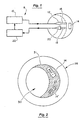
- the system 8 includes a transducer 12 (which is typically disposed within an imaging catheter as is known in the art) which is driven by an exciter 10 to excite a region of interest (ROI) 14 with ultrasonic energy 16. Reflections 18 of the ultrasonic energy are observed at a receiver 20 during a frame. Signal processing techniques in a signal processor 22 analyze those reflections. The information extracted is used to refine the excitation and observations about current and/or subsequent frames and to refine the characterization of the frame as an object model.
- system 8 preferably also includes a display screen to display each frame of data, which is typically a cross section of the image.
- Various entry devices such as keyboards, pointing devices, mice, and the like, are preferably provided to allow the user to interact with the system.
- An exemplary processor that may be used with the invention is included within a Galaxy medical imaging system, commercially available from Boston Scientific Corporation.
- Fig. 2 illustrates a typical IVUS object 26 (such as plaque) in an image 28 that is produced on the display screen of system 8 and represents a frame of data collected by receiver 20.
- a typical IVUS object 26 such as plaque
- image 28 is produced on the display screen of system 8 and represents a frame of data collected by receiver 20.
- ROIs 14, 14' may be placed onto object 26 using one of the entry devices of the system as previously described.
- ROIs 14 and 14' may be of any size or geometry. Further, any number of ROIs may be employed.
- a lumen 30 surround by a vessel wall 31 illustrates how the plaque 26 fills the lumen 30.
- the different objects are characterized by differently displayed visual intensities as well as the homogeneity of the image.
- reflections from ROIs 14, 14' preferably exhibit a spectrum differing from that of any surrounding objects.
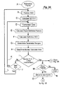
- a flow chart of an exemplary inventive process begins by selecting a reference frame which comprises the observed reflection signal for a time sample of interest (Step A).
- the user is allowed to select the reference frame.
- the selected frame is preferably the frame which best shows object 26 (see Fig. 2).
- ROI 14 (see Fig. 2), which may be essentially any size or geometry, is then positioned on the desired object 26 (Step B). This may be accomplished, for example, by using a mouse to outline ROI 14 on the display screen.
- a two-dimensional fast Fourier transform is calculated from the observed time-domain data of ROI 14 to obtain frequency-domain data, i.e., a spectrum of the observational data in x and y (Step C).
- the data is then compressed by retaining only a percentage of the spectral components which represent ROI 14 (Step D).
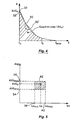
- Such a process is illustrated graphically in Fig. 4.
- the spectral components between f o and f c are kept.
- the value f c i.e. the amount of desired compression, is selected based on a percentage of the original area of the compressed data that is desired to be maintained, e.g., 90% of the area under the curve of Fig. 4. This value may be varied to improve the results of the method as described hereinafter.
- Step E Compression of the data may be accomplished, for example, by using a low pass filter.
- the method may employ a high pass filter, a band pass filter, a selective filter, and the like.
- the compressed spectral components are then used to compute two key object identification parameters (Step E).
- these two parameters are the zero frequency magnitude AVG o , i.e., the magnitude of the frequency at f 0 (also referred to as the amplitude of zero frequency), and the sum SA of the frequency magnitudes, i.e. the area under the spectral amplitude density curve (also referred to as the spectral amplitude distribution). This area is graphically represented by the cross-hatched area under the curve of Fig. 4.
- these two parameters are particularly advantageous in that they may be used to characterize various physical characteristics of the object within the patient.
- the definition ROI is a subset of the originally selected ROI and is used to obtain a range of acceptable object identification parameters.
- the definition ROI is preferably selected so that is has a similar geometric shape as the original ROI but with smaller dimensions.
- the dimensions of the definition ROI may be the square root of 64, or 8 by 8 components.
- the amount of compression can be varied to enhance the results of the method, if needed.
- the definition ROI is then moved through the originally selected region of interest to unique locations. At each unique location (which may be as close as pixel to pixel) a FFT is performed on the definition ROI and the two object identifying parameters are calculated in a manner similar to the originally selected ROI. These values are then used to determine an acceptable range of object identifying parameters (Step G), since each of the definition parameters belong to the originally observed ROI. This range is illustrated graphically in Fig. 5.
- the definition ROI is moved to selected locations in the image and FFTs of the time-domain data are performed to obtain frequency-domain data for each location of the definition ROI in the original image. From this data, the two object identification parameters are extracted and evaluated to see if they fall within the range of Fig. 5. If so, the locations are marked or flagged to indicate that these locations are part of the object having the originally selected ROI.
- Step H a border of the object is "drawn" by the processor around the flagged locations.
- the area of the object may easily be calculated simply by summing the areas of the flagged locations.
- Step I The user is then presented with the results (by displaying the image with the border on the display screen) and asked to indicate whether the border as presented is correct or otherwise acceptable (Step I). For example, a window may be generated on the display screen to ask the user if the border is acceptable.
- a confirmation of the border is a confirmation that the object definition is correct. If the border is not confirmed as correct, the user is given the choice (Step J) of optimizing the ROI (Step K) or adding another ROI (such as ROI 14') (Step L).
- Step J the choice
- Step J optimizing the ROI
- Step L the user is given the choice (Step J) of optimizing the ROI (Step K) or adding another ROI (such as ROI 14') (Step L).
- the whole process (Steps B through H) is repeated for each added ROI.
- a portion of the process (Steps D through H) is repeated if the ROI is to be optimized.
- the amount of or type of compression may be varied. Also, the range of acceptable object identifying
- the foregoing process (beginning with Step L) is used for confirming the border of a complex object and thus the definition of a complex object.
- the complex object is defined by the combined borders of each individual object detected for each individual definition ROI as shown in Fig. 6.
- Step I the process proceeds to the next frame, first determining if there are more frames (Step M). If there are no more frames, the process ends (Step N). If there are still more frames, the process proceeds to the next frame (Step O).
- processing on subsequent frames proceeds with positioning of a definition ROI (which is preferably the same definition ROI previously calculated) at a center of mass of the object (which is approximated from the object in the previous frame) (Step P).
- a two-dimensional fast Fourier transform (FFT) is then calculated on the time-domain data (Step Q) in order to calculate object definition parameters (Step R) and then identify the object definition parameters (Step S), using the same techniques used previously.
- the parameters are examined to determine if they are within the acceptable range as previously calculated. If so, the location of the definition ROI is flagged as defining an area belonging to the object. So long as there is an unprocessed definition ROI (Step T), the process of Steps P through S repeats for all definition ROIs. After all definition ROIs have been considered, the borders of the final object are determined and the area contained therein is calculated (Step U) in a manner similar to that previously described.
- FFT fast Fourier transform
- the new area value is compared with the area value computed for the previous frame to determine whether it is within an acceptable range (Step V). If it is, the process proceeds to the next frame (Step M, Fig. 3A). If not, the process enters an adaptive loop (Step W) repeating steps P through U) with a change of position and size of the definition ROIs or a change in the range of acceptable parameters in order to obtain an area value within an acceptable range.
- the loop of steps P through U provides an adaptive way to compensate for such discrepancies. More specifically, the value of f c (see Fig. 2) may be varied (or the data may be compressed in any way). Further, the starting point of the definition ROI may be moved away from the center of mass. Still further, the range of acceptable object identification parameters may be varied. In the event that convergence is not obtained, the system may produce a message indicating that the results did not comply with the definition.
- Fig. 4 is a spectrum diagram of one ROI 14 from the average frequency f 0 to a frequency beyond the maximum observed frequency f max .
- a value f c denotes the upper limit of the spectrum of the compressed values.
- the two parameters used to develop an object definition are 1) the zero frequency magnitude AVG, i.e., the amplitude at f 0 , and 2) the spectral area SA, namely, the area bordered by the axes, the compression cutoff and the amplitude-frequency plot 30. This plot differs with each definition ROI, as represented by plot 30', just as the zero frequency magnitude AVG differs between amplitude 32 and 32'.
- Fig. 5 depicts a relationship between spectral areas SA and zero frequency magnitudes AVG, and more particularly shows the object definition range as computed in Step G (Fig. 3A).
- the parameter AVG may vary between a minimum 34 and a maximum 36
- the parameter SA may vary between a minimum 38 and a maximum 40 thus establishing the allowable parameter variations 42 for the definition of the object's signature. Parameters found within this range are thus identifiable with the object.
- the object definition algorithm produces an object definition 48, e.g., for plaque, which for purposes of illustration consists of two objects 50 and 52.
- An object border 54 combines borders 56, 58 resulting from processing of two ROIs defining the object.
- the object area is thereafter useable as a feedback parameter for the adaptive object identification algorithm as disclosed herein.
- the object identification algorithm in frames other than the reference frame uses the results of the previous frame to identify the object. If the object area in such a frame differs more than an accepted fraction from the previous frame, then the adaptive mechanisms change the positions and sizes of definition ROIs until the resultant new area is within an accepted fraction of the area in the previous frame. If there is no solution to the optimization process (i.e., the solution does not converge), then a best available approximation may be chosen as the solution, and the border area may be denoted as uncertain.
- FIG. 7 an example of a spectrum diagram of a region of interest showing how the object identification parameters relate to the physical characteristics of the object, i.e. the object within the patient.
- the ultrasound image is taken within a vessel having a region of plaque.
- the AVG axis is representative of the intensity of the ultrasound image. In turn, this corresponds to the physical composition of the actual physical image, e.g., its hardness.
- the f axis is representative of the spacial structure of the ultrasound image. In turn, this corresponds to the spacial structure, e.g. homogeneity, of the physical object.
- the actual physical object is composed of lipid plaque.
- region 62 the physical object is composed of mixed plaque.
- the physical object is composed of blood
- region 66 the physical object is composed of strong calcified plaque that is transitioning into tissue.
- the f o and SA values as object identification parameters, the actual physical nature of the object may be characterized.
- the methods of the invention are patient specific and will vary from patient to patient.
- the parameters may be saved and compared with later calculated parameters to determine if a treatment is effective.
Description
Claims (1)
- An ultrasonic imaging system comprising:a processor;a memory to store in-vivo ultrasound image data in a plurality of frames;a display screen coupled to the processor for displaying images from each frame of data, wherein the images include at least one object; wherein the processor:identifies the object within each image by moving a region of interest to different locations in the image and evaluating object identifying parameters at the different locations to determine if the parameters fall within an acceptable range of object identifying parameters indicative of the object;computes the area of the object within each of the frames based on the locations having the parameters which fall within the acceptable range;compares the areas of two adjacent frames; andrecomputes the area of the object within one of the adjacent frames using a different range of object identifying parameters if the difference between the two areas exceeds a predetermined amount.
Applications Claiming Priority (3)
| Application Number | Priority Date | Filing Date | Title |
|---|---|---|---|
| US09/165,670 US6120445A (en) | 1998-10-02 | 1998-10-02 | Method and apparatus for adaptive cross-sectional area computation of IVUS objects using their statistical signatures |
| US165670 | 1998-10-02 | ||
| PCT/IB1999/001541 WO2000019903A1 (en) | 1998-10-02 | 1999-09-13 | Adaptive cross-sectional area computation using statistical signatures |
Publications (2)
| Publication Number | Publication Date |
|---|---|
| EP1117331A1 EP1117331A1 (en) | 2001-07-25 |
| EP1117331B1 true EP1117331B1 (en) | 2005-05-04 |
Family
ID=22599936
Family Applications (1)
| Application Number | Title | Priority Date | Filing Date |
|---|---|---|---|
| EP99940431A Expired - Lifetime EP1117331B1 (en) | 1998-10-02 | 1999-09-13 | Adaptive cross-sectional area computation using statistical signatures |
Country Status (6)
| Country | Link |
|---|---|
| US (4) | US6120445A (en) |
| EP (1) | EP1117331B1 (en) |
| JP (1) | JP4544745B2 (en) |
| CA (1) | CA2340247C (en) |
| DE (1) | DE69925139T2 (en) |
| WO (1) | WO2000019903A1 (en) |
Cited By (17)
| Publication number | Priority date | Publication date | Assignee | Title |
|---|---|---|---|---|
| US9999371B2 (en) | 2007-11-26 | 2018-06-19 | C. R. Bard, Inc. | Integrated system for intravascular placement of a catheter |
| US10046139B2 (en) | 2010-08-20 | 2018-08-14 | C. R. Bard, Inc. | Reconfirmation of ECG-assisted catheter tip placement |
| US10105121B2 (en) | 2007-11-26 | 2018-10-23 | C. R. Bard, Inc. | System for placement of a catheter including a signal-generating stylet |
| US10231753B2 (en) | 2007-11-26 | 2019-03-19 | C. R. Bard, Inc. | Insertion guidance system for needles and medical components |
| US10231643B2 (en) | 2009-06-12 | 2019-03-19 | Bard Access Systems, Inc. | Apparatus and method for catheter navigation and tip location |
| US10238418B2 (en) | 2007-11-26 | 2019-03-26 | C. R. Bard, Inc. | Apparatus for use with needle insertion guidance system |
| US10271762B2 (en) | 2009-06-12 | 2019-04-30 | Bard Access Systems, Inc. | Apparatus and method for catheter navigation using endovascular energy mapping |
| US10602958B2 (en) | 2007-11-26 | 2020-03-31 | C. R. Bard, Inc. | Systems and methods for guiding a medical instrument |
| US10751509B2 (en) | 2007-11-26 | 2020-08-25 | C. R. Bard, Inc. | Iconic representations for guidance of an indwelling medical device |
| US10849695B2 (en) | 2007-11-26 | 2020-12-01 | C. R. Bard, Inc. | Systems and methods for breaching a sterile field for intravascular placement of a catheter |
| US10863920B2 (en) | 2014-02-06 | 2020-12-15 | C. R. Bard, Inc. | Systems and methods for guidance and placement of an intravascular device |
| US10973584B2 (en) | 2015-01-19 | 2021-04-13 | Bard Access Systems, Inc. | Device and method for vascular access |
| US10992079B2 (en) | 2018-10-16 | 2021-04-27 | Bard Access Systems, Inc. | Safety-equipped connection systems and methods thereof for establishing electrical connections |
| US11000207B2 (en) | 2016-01-29 | 2021-05-11 | C. R. Bard, Inc. | Multiple coil system for tracking a medical device |
| US11027101B2 (en) | 2008-08-22 | 2021-06-08 | C. R. Bard, Inc. | Catheter assembly including ECG sensor and magnetic assemblies |
| US11026630B2 (en) | 2015-06-26 | 2021-06-08 | C. R. Bard, Inc. | Connector interface for ECG-based catheter positioning system |
| US11207496B2 (en) | 2005-08-24 | 2021-12-28 | C. R. Bard, Inc. | Stylet apparatuses and methods of manufacture |
Families Citing this family (166)
| Publication number | Priority date | Publication date | Assignee | Title |
|---|---|---|---|---|
| US6120445A (en) * | 1998-10-02 | 2000-09-19 | Scimed Life Systems, Inc. | Method and apparatus for adaptive cross-sectional area computation of IVUS objects using their statistical signatures |
| JP4101392B2 (en) * | 1999-04-08 | 2008-06-18 | 富士フイルム株式会社 | Image quantification method and apparatus |
| US6200268B1 (en) * | 1999-09-10 | 2001-03-13 | The Cleveland Clinic Foundation | Vascular plaque characterization |
| WO2002041752A2 (en) * | 2000-11-24 | 2002-05-30 | U-Systems, Inc. | Method and system for instant biopsy specimen analysis |
| WO2002100249A2 (en) * | 2001-06-13 | 2002-12-19 | Cardiovascular Innovations, Inc. | Apparatus and method for ultrasonically identifying vulnerable plaque |
| NL1019612C2 (en) * | 2001-12-19 | 2003-06-20 | Gemeente Amsterdam | Steam superheater. |
| US6776760B2 (en) * | 2002-03-06 | 2004-08-17 | Alfred E. Mann Institute For Biomedical Engineering At The University Of Southern California | Multi-mode processing for ultrasonic imaging |
| US6817982B2 (en) * | 2002-04-19 | 2004-11-16 | Sonosite, Inc. | Method, apparatus, and product for accurately determining the intima-media thickness of a blood vessel |
| EP1534139B1 (en) * | 2002-08-26 | 2018-12-19 | The Cleveland Clinic Foundation | System and method of characterizing vascular tissue |
| US7359554B2 (en) * | 2002-08-26 | 2008-04-15 | Cleveland Clinic Foundation | System and method for identifying a vascular border |
| US7074188B2 (en) | 2002-08-26 | 2006-07-11 | The Cleveland Clinic Foundation | System and method of characterizing vascular tissue |
| US7927275B2 (en) * | 2002-08-26 | 2011-04-19 | The Cleveland Clinic Foundation | System and method of aquiring blood-vessel data |
| US6835177B2 (en) * | 2002-11-06 | 2004-12-28 | Sonosite, Inc. | Ultrasonic blood vessel measurement apparatus and method |
| US7998073B2 (en) * | 2003-08-04 | 2011-08-16 | Imacor Inc. | Ultrasound imaging with reduced noise |
| WO2005025425A1 (en) * | 2003-09-12 | 2005-03-24 | Hitachi Medical Corporation | Ultrasonograph |
| US20050070796A1 (en) * | 2003-09-30 | 2005-03-31 | Fuji Photo Film Co., Ltd. | Ultrasonic diagnosing apparatus |
| KR100601933B1 (en) * | 2003-11-18 | 2006-07-14 | 삼성전자주식회사 | Method and apparatus of human detection and privacy protection method and system employing the same |
| JP4913601B2 (en) * | 2003-11-26 | 2012-04-11 | イマコー・インコーポレーテッド | Transesophageal ultrasound using a thin probe |
| JP3867080B2 (en) * | 2003-12-11 | 2007-01-10 | ジーイー・メディカル・システムズ・グローバル・テクノロジー・カンパニー・エルエルシー | Ultrasonic diagnostic equipment |
| US7874990B2 (en) * | 2004-01-14 | 2011-01-25 | The Cleveland Clinic Foundation | System and method for determining a transfer function |
| US7215802B2 (en) * | 2004-03-04 | 2007-05-08 | The Cleveland Clinic Foundation | System and method for vascular border detection |
| KR100686289B1 (en) * | 2004-04-01 | 2007-02-23 | 주식회사 메디슨 | Apparatus and method for forming 3d ultrasound image using volume data in the contour of a target object image |
| US7460716B2 (en) * | 2004-09-13 | 2008-12-02 | Boston Scientific Scimed, Inc. | Systems and methods for producing a dynamic classified image |
| JP4575737B2 (en) * | 2004-09-29 | 2010-11-04 | 富士フイルム株式会社 | Ultrasonic imaging device |
| JP4575738B2 (en) * | 2004-09-29 | 2010-11-04 | 富士フイルム株式会社 | Ultrasonic image boundary extraction method, ultrasonic image boundary extraction device, and ultrasonic imaging device |
| US7713206B2 (en) * | 2004-09-29 | 2010-05-11 | Fujifilm Corporation | Ultrasonic imaging apparatus |
| US7771355B2 (en) * | 2004-10-30 | 2010-08-10 | Sonowise, Inc. | System and method for medical imaging with robust mode switching via serial channel |
| US8287455B2 (en) * | 2004-10-30 | 2012-10-16 | Sonowise, Inc. | Synchronized power supply for medical imaging |
| US8016758B2 (en) * | 2004-10-30 | 2011-09-13 | Sonowise, Inc. | User interface for medical imaging including improved pan-zoom control |
| US7708691B2 (en) * | 2005-03-03 | 2010-05-04 | Sonowise, Inc. | Apparatus and method for real time 3D body object scanning without touching or applying pressure to the body object |
| US8409103B2 (en) | 2005-05-06 | 2013-04-02 | Vasonova, Inc. | Ultrasound methods of positioning guided vascular access devices in the venous system |
| US20090118612A1 (en) | 2005-05-06 | 2009-05-07 | Sorin Grunwald | Apparatus and Method for Vascular Access |
| US7831081B2 (en) * | 2005-08-15 | 2010-11-09 | Boston Scientific Scimed, Inc. | Border detection in medical image analysis |
| US20070083110A1 (en) * | 2005-10-09 | 2007-04-12 | Sonowise, Inc. | Programmable phase velocity in an ultrasonic imaging system |
| US20070238991A1 (en) * | 2006-01-25 | 2007-10-11 | Jaltec Biomedical Inc. | Ultrasound method and apparatus for characterizing and identifying biological tissues |
| US9867530B2 (en) | 2006-08-14 | 2018-01-16 | Volcano Corporation | Telescopic side port catheter device with imaging system and method for accessing side branch occlusions |
| US7794407B2 (en) | 2006-10-23 | 2010-09-14 | Bard Access Systems, Inc. | Method of locating the tip of a central venous catheter |
| US8388546B2 (en) | 2006-10-23 | 2013-03-05 | Bard Access Systems, Inc. | Method of locating the tip of a central venous catheter |
| US20080119735A1 (en) * | 2006-11-20 | 2008-05-22 | Sonowise, Inc. | Ultrasound imaging system and method with offset alternate-mode line |
| WO2009003138A1 (en) | 2007-06-26 | 2008-12-31 | Vasonova, Inc. | Apparatus and method for endovascular device guiding and positioning using physiological parameters |
| US9596993B2 (en) | 2007-07-12 | 2017-03-21 | Volcano Corporation | Automatic calibration systems and methods of use |
| WO2009009802A1 (en) | 2007-07-12 | 2009-01-15 | Volcano Corporation | Oct-ivus catheter for concurrent luminal imaging |
| EP2178442B1 (en) | 2007-07-12 | 2017-09-06 | Volcano Corporation | Catheter for in vivo imaging |
| US10449330B2 (en) | 2007-11-26 | 2019-10-22 | C. R. Bard, Inc. | Magnetic element-equipped needle assemblies |
| US10524691B2 (en) | 2007-11-26 | 2020-01-07 | C. R. Bard, Inc. | Needle assembly including an aligned magnetic element |
| US8849382B2 (en) | 2007-11-26 | 2014-09-30 | C. R. Bard, Inc. | Apparatus and display methods relating to intravascular placement of a catheter |
| US8478382B2 (en) | 2008-02-11 | 2013-07-02 | C. R. Bard, Inc. | Systems and methods for positioning a catheter |
| US9451929B2 (en) | 2008-04-17 | 2016-09-27 | Boston Scientific Scimed, Inc. | Degassing intravascular ultrasound imaging systems with sealed catheters filled with an acoustically-favorable medium and methods of making and using |
| US9549713B2 (en) | 2008-04-24 | 2017-01-24 | Boston Scientific Scimed, Inc. | Methods, systems, and devices for tissue characterization and quantification using intravascular ultrasound signals |
| WO2009132188A1 (en) * | 2008-04-24 | 2009-10-29 | Boston Scientific Scimed, Inc. | Methods, systems, and devices for tissue characterization by spectral similarity of intravascular ultrasound signals |
| WO2009137403A1 (en) * | 2008-05-05 | 2009-11-12 | Boston Scientific Scimed, Inc. | Shielding for intravascular ultrasound imaging systems and methods of making and using |
| US8197413B2 (en) * | 2008-06-06 | 2012-06-12 | Boston Scientific Scimed, Inc. | Transducers, devices and systems containing the transducers, and methods of manufacture |
| CN102119341B (en) * | 2008-08-12 | 2014-01-08 | 皇家飞利浦电子股份有限公司 | Method of meshing and calculating a volume in an ultrasound imaging system |
| EP2169415A1 (en) * | 2008-09-30 | 2010-03-31 | Siemens Schweiz AG | Method for automatic quality control of in-vivo human brain MRI images |
| US8437833B2 (en) | 2008-10-07 | 2013-05-07 | Bard Access Systems, Inc. | Percutaneous magnetic gastrostomy |
| US20100168582A1 (en) * | 2008-12-29 | 2010-07-01 | Boston Scientific Scimed, Inc. | High frequency transducers and methods of making the transducers |
| US20100179434A1 (en) * | 2009-01-09 | 2010-07-15 | Boston Scientific Scimed, Inc. | Systems and methods for making and using intravascular ultrasound systems with photo-acoustic imaging capabilities |
| US20100179432A1 (en) | 2009-01-09 | 2010-07-15 | Boston Scientific Scimed, Inc. | Systems and methods for making and using intravascular ultrasound systems with photo-acoustic imaging capabilities |
| WO2010093603A1 (en) | 2009-02-11 | 2010-08-19 | Boston Scientific Scimed, Inc. | Insulated ablation catheter devices and methods of use |
| US8298149B2 (en) | 2009-03-31 | 2012-10-30 | Boston Scientific Scimed, Inc. | Systems and methods for making and using a motor distally-positioned within a catheter of an intravascular ultrasound imaging system |
| US20100249604A1 (en) | 2009-03-31 | 2010-09-30 | Boston Scientific Corporation | Systems and methods for making and using a motor distally-positioned within a catheter of an intravascular ultrasound imaging system |
| US20100249588A1 (en) | 2009-03-31 | 2010-09-30 | Boston Scientific Scimed, Inc. | Systems and methods for making and using intravascular imaging systems with multiple pullback rates |
| US8647281B2 (en) * | 2009-03-31 | 2014-02-11 | Boston Scientific Scimed, Inc. | Systems and methods for making and using an imaging core of an intravascular ultrasound imaging system |
| US8545412B2 (en) * | 2009-05-29 | 2013-10-01 | Boston Scientific Scimed, Inc. | Systems and methods for making and using image-guided intravascular and endocardial therapy systems |
| US20100305442A1 (en) * | 2009-05-29 | 2010-12-02 | Boston Scientific Scimed, Inc. | Systems and methods for implementing a data management system for catheter-based imaging systems |
| US9445734B2 (en) | 2009-06-12 | 2016-09-20 | Bard Access Systems, Inc. | Devices and methods for endovascular electrography |
| CN102802514B (en) | 2009-06-12 | 2015-12-02 | 巴德阿克塞斯系统股份有限公司 | Catheter tip positioning equipment |
| KR101358498B1 (en) | 2009-06-30 | 2014-02-05 | 보스톤 싸이엔티픽 싸이메드 인코포레이티드 | Map and ablate open irrigated hybrid catheter |
| US20110071400A1 (en) * | 2009-09-23 | 2011-03-24 | Boston Scientific Scimed, Inc. | Systems and methods for making and using intravascular ultrasound imaging systems with sealed imaging cores |
| US20110071401A1 (en) | 2009-09-24 | 2011-03-24 | Boston Scientific Scimed, Inc. | Systems and methods for making and using a stepper motor for an intravascular ultrasound imaging system |
| AU2010300677B2 (en) | 2009-09-29 | 2014-09-04 | C.R. Bard, Inc. | Stylets for use with apparatus for intravascular placement of a catheter |
| US11103213B2 (en) | 2009-10-08 | 2021-08-31 | C. R. Bard, Inc. | Spacers for use with an ultrasound probe |
| US10639008B2 (en) | 2009-10-08 | 2020-05-05 | C. R. Bard, Inc. | Support and cover structures for an ultrasound probe head |
| US8396276B2 (en) * | 2009-10-26 | 2013-03-12 | Boston Scientific Scimed, Inc. | Systems and methods for performing an image-based gating procedure during an IVUS imaging procedure |
| US20110098573A1 (en) * | 2009-10-27 | 2011-04-28 | Boston Scientific Scimed, Inc. | Systems and methods for coupling a transducer to a control module of an intravascular ultrasound imaging system |
| US8523778B2 (en) * | 2009-11-25 | 2013-09-03 | Boston Scientific Scimed, Inc. | Systems and methods for flushing air from a catheter of an intravascular ultrasound imaging system |
| US9179827B2 (en) * | 2009-12-15 | 2015-11-10 | Boston Scientific Scimed, Inc. | Systems and methods for determining the position and orientation of medical devices inserted into a patient |
| US20110160586A1 (en) * | 2009-12-29 | 2011-06-30 | Boston Scientific Scimed, Inc. | Systems and methods for multi-frequency imaging of patient tissue using intravascular ultrasound imaging systems |
| US8487932B1 (en) * | 2010-08-30 | 2013-07-16 | Disney Enterprises, Inc. | Drawing figures in computer-based drawing applications |
| US8427483B1 (en) | 2010-08-30 | 2013-04-23 | Disney Enterprises. Inc. | Drawing figures in computer-based drawing applications |
| US20120065506A1 (en) | 2010-09-10 | 2012-03-15 | Scott Smith | Mechanical, Electromechanical, and/or Elastographic Assessment for Renal Nerve Ablation |
| EP2632338B1 (en) | 2010-10-28 | 2015-07-01 | Boston Scientific Scimed, Inc. | Systems and methods for reducing non-uniform rotation distortion in ultrasound images |
| WO2012058461A1 (en) | 2010-10-29 | 2012-05-03 | C.R.Bard, Inc. | Bioimpedance-assisted placement of a medical device |
| EP2637568B1 (en) | 2010-11-08 | 2017-04-12 | Vasonova, Inc. | Endovascular navigation system |
| WO2012064413A1 (en) | 2010-11-12 | 2012-05-18 | Boston Scientific Scimed, Inc. | Systems and methods for making and using rotational transducers for concurrently imaging blood flow and tissue |
| US20120130242A1 (en) | 2010-11-24 | 2012-05-24 | Boston Scientific Scimed, Inc. | Systems and methods for concurrently displaying a plurality of images using an intravascular ultrasound imaging system |
| EP2642922A1 (en) | 2010-11-24 | 2013-10-02 | Boston Scientific Scimed, Inc. | Systems and methods for detecting and displaying body lumen bifurcations |
| US11141063B2 (en) | 2010-12-23 | 2021-10-12 | Philips Image Guided Therapy Corporation | Integrated system architectures and methods of use |
| US9089340B2 (en) | 2010-12-30 | 2015-07-28 | Boston Scientific Scimed, Inc. | Ultrasound guided tissue ablation |
| US20120172698A1 (en) | 2010-12-30 | 2012-07-05 | Boston Scientific Scimed, Inc. | Imaging system |
| US11040140B2 (en) | 2010-12-31 | 2021-06-22 | Philips Image Guided Therapy Corporation | Deep vein thrombosis therapeutic methods |
| WO2012135197A1 (en) | 2011-03-30 | 2012-10-04 | Boston Scientific Scimed, Inc. | Systems and methods for flushing bubbles from a catheter of an intravascular ultrasound imaging system |
| US20120283569A1 (en) * | 2011-05-04 | 2012-11-08 | Boston Scientific Scimed, Inc. | Systems and methods for navigating and visualizing intravascular ultrasound sequences |
| EP2713888B1 (en) | 2011-06-01 | 2019-09-04 | Boston Scientific Scimed, Inc. | Ablation probe with ultrasonic imaging capabilities |
| EP2729073A4 (en) | 2011-07-06 | 2015-03-11 | Bard Inc C R | Needle length determination and calibration for insertion guidance system |
| USD724745S1 (en) | 2011-08-09 | 2015-03-17 | C. R. Bard, Inc. | Cap for an ultrasound probe |
| USD699359S1 (en) | 2011-08-09 | 2014-02-11 | C. R. Bard, Inc. | Ultrasound probe head |
| WO2013033489A1 (en) | 2011-08-31 | 2013-03-07 | Volcano Corporation | Optical rotary joint and methods of use |
| CN103917185A (en) | 2011-09-14 | 2014-07-09 | 波士顿科学西美德公司 | Ablation device with ionically conductive balloon |
| EP2755587B1 (en) | 2011-09-14 | 2018-11-21 | Boston Scientific Scimed, Inc. | Ablation device with multiple ablation modes |
| US9271696B2 (en) | 2011-09-22 | 2016-03-01 | Boston Scientific Scimed, Inc. | Ultrasound imaging systems with bias circuitry and methods of making and using |
| US9211107B2 (en) | 2011-11-07 | 2015-12-15 | C. R. Bard, Inc. | Ruggedized ultrasound hydrogel insert |
| US9241761B2 (en) | 2011-12-28 | 2016-01-26 | Koninklijke Philips N.V. | Ablation probe with ultrasonic imaging capability |
| EP2802282A1 (en) | 2012-01-10 | 2014-11-19 | Boston Scientific Scimed, Inc. | Electrophysiology system |
| US8945015B2 (en) | 2012-01-31 | 2015-02-03 | Koninklijke Philips N.V. | Ablation probe with fluid-based acoustic coupling for ultrasonic tissue imaging and treatment |
| EP2846686B1 (en) | 2012-05-07 | 2018-01-03 | Vasonova, Inc. | System for detection of the superior vena cava area and the cavoatrial junction |
| WO2013188833A2 (en) | 2012-06-15 | 2013-12-19 | C.R. Bard, Inc. | Apparatus and methods for detection of a removable cap on an ultrasound probe |
| US11272845B2 (en) | 2012-10-05 | 2022-03-15 | Philips Image Guided Therapy Corporation | System and method for instant and automatic border detection |
| US10070827B2 (en) | 2012-10-05 | 2018-09-11 | Volcano Corporation | Automatic image playback |
| US9858668B2 (en) | 2012-10-05 | 2018-01-02 | Volcano Corporation | Guidewire artifact removal in images |
| US10568586B2 (en) | 2012-10-05 | 2020-02-25 | Volcano Corporation | Systems for indicating parameters in an imaging data set and methods of use |
| US9307926B2 (en) | 2012-10-05 | 2016-04-12 | Volcano Corporation | Automatic stent detection |
| US9324141B2 (en) | 2012-10-05 | 2016-04-26 | Volcano Corporation | Removal of A-scan streaking artifact |
| JP2015532536A (en) | 2012-10-05 | 2015-11-09 | デイビッド ウェルフォード, | System and method for amplifying light |
| US9286673B2 (en) | 2012-10-05 | 2016-03-15 | Volcano Corporation | Systems for correcting distortions in a medical image and methods of use thereof |
| US9367965B2 (en) | 2012-10-05 | 2016-06-14 | Volcano Corporation | Systems and methods for generating images of tissue |
| US9292918B2 (en) | 2012-10-05 | 2016-03-22 | Volcano Corporation | Methods and systems for transforming luminal images |
| US9840734B2 (en) | 2012-10-22 | 2017-12-12 | Raindance Technologies, Inc. | Methods for analyzing DNA |
| EP2931132B1 (en) | 2012-12-13 | 2023-07-05 | Philips Image Guided Therapy Corporation | System for targeted cannulation |
| US10942022B2 (en) | 2012-12-20 | 2021-03-09 | Philips Image Guided Therapy Corporation | Manual calibration of imaging system |
| US10939826B2 (en) | 2012-12-20 | 2021-03-09 | Philips Image Guided Therapy Corporation | Aspirating and removing biological material |
| US9709379B2 (en) | 2012-12-20 | 2017-07-18 | Volcano Corporation | Optical coherence tomography system that is reconfigurable between different imaging modes |
| US11406498B2 (en) | 2012-12-20 | 2022-08-09 | Philips Image Guided Therapy Corporation | Implant delivery system and implants |
| CA2895502A1 (en) | 2012-12-20 | 2014-06-26 | Jeremy Stigall | Smooth transition catheters |
| JP2016506276A (en) | 2012-12-20 | 2016-03-03 | ジェレミー スティガール, | Locate the intravascular image |
| US10058284B2 (en) | 2012-12-21 | 2018-08-28 | Volcano Corporation | Simultaneous imaging, monitoring, and therapy |
| US10413317B2 (en) | 2012-12-21 | 2019-09-17 | Volcano Corporation | System and method for catheter steering and operation |
| WO2014100606A1 (en) | 2012-12-21 | 2014-06-26 | Meyer, Douglas | Rotational ultrasound imaging catheter with extended catheter body telescope |
| EP2934280B1 (en) | 2012-12-21 | 2022-10-19 | Mai, Jerome | Ultrasound imaging with variable line density |
| US9612105B2 (en) | 2012-12-21 | 2017-04-04 | Volcano Corporation | Polarization sensitive optical coherence tomography system |
| CA2895940A1 (en) | 2012-12-21 | 2014-06-26 | Andrew Hancock | System and method for multipath processing of image signals |
| US9486143B2 (en) | 2012-12-21 | 2016-11-08 | Volcano Corporation | Intravascular forward imaging device |
| US10191220B2 (en) | 2012-12-21 | 2019-01-29 | Volcano Corporation | Power-efficient optical circuit |
| EP2936626A4 (en) | 2012-12-21 | 2016-08-17 | David Welford | Systems and methods for narrowing a wavelength emission of light |
| US10332228B2 (en) | 2012-12-21 | 2019-06-25 | Volcano Corporation | System and method for graphical processing of medical data |
| JP6059369B2 (en) | 2013-02-28 | 2017-01-11 | ボストン サイエンティフィック サイムド,インコーポレイテッドBoston Scientific Scimed,Inc. | Medical imaging assembly and non-transitory computer readable medium having an array of transducers |
| WO2014134454A1 (en) | 2013-03-01 | 2014-09-04 | Boston Scientific Scimed, Inc. | Systems and methods for lumen border detection in intravascular ultrasound sequences |
| WO2014138555A1 (en) | 2013-03-07 | 2014-09-12 | Bernhard Sturm | Multimodal segmentation in intravascular images |
| US10226597B2 (en) | 2013-03-07 | 2019-03-12 | Volcano Corporation | Guidewire with centering mechanism |
| EP2967391A4 (en) | 2013-03-12 | 2016-11-02 | Donna Collins | Systems and methods for diagnosing coronary microvascular disease |
| US20140276923A1 (en) | 2013-03-12 | 2014-09-18 | Volcano Corporation | Vibrating catheter and methods of use |
| JP6339170B2 (en) | 2013-03-13 | 2018-06-06 | ジンヒョン パーク | System and method for generating images from a rotating intravascular ultrasound device |
| US9301687B2 (en) | 2013-03-13 | 2016-04-05 | Volcano Corporation | System and method for OCT depth calibration |
| US11026591B2 (en) | 2013-03-13 | 2021-06-08 | Philips Image Guided Therapy Corporation | Intravascular pressure sensor calibration |
| US10219887B2 (en) | 2013-03-14 | 2019-03-05 | Volcano Corporation | Filters with echogenic characteristics |
| US10292677B2 (en) | 2013-03-14 | 2019-05-21 | Volcano Corporation | Endoluminal filter having enhanced echogenic properties |
| US20160030151A1 (en) | 2013-03-14 | 2016-02-04 | Volcano Corporation | Filters with echogenic characteristics |
| US10716536B2 (en) | 2013-07-17 | 2020-07-21 | Tissue Differentiation Intelligence, Llc | Identifying anatomical structures |
| US10154826B2 (en) | 2013-07-17 | 2018-12-18 | Tissue Differentiation Intelligence, Llc | Device and method for identifying anatomical structures |
| EP3043717B1 (en) | 2013-09-11 | 2019-03-13 | Boston Scientific Scimed, Inc. | Systems for selection and displaying of images using an intravascular ultrasound imaging system |
| US10524684B2 (en) | 2014-10-13 | 2020-01-07 | Boston Scientific Scimed Inc | Tissue diagnosis and treatment using mini-electrodes |
| EP3209234B1 (en) | 2014-10-24 | 2023-11-29 | Boston Scientific Scimed Inc. | Medical devices with a flexible electrode assembly coupled to an ablation tip |
| EP3232969A1 (en) | 2014-12-18 | 2017-10-25 | Boston Scientific Scimed Inc. | Real-time morphology analysis for lesion assessment |
| CN107567309A (en) | 2015-05-05 | 2018-01-09 | 波士顿科学国际有限公司 | There are the system and method for the expandable material on ultrasonic image-forming system transducer |
| JP6626192B2 (en) | 2015-10-09 | 2019-12-25 | ボストン サイエンティフィック サイムド,インコーポレイテッドBoston Scientific Scimed,Inc. | Intravascular ultrasound system, catheter and method with manual pullback mechanism |
| US11701086B1 (en) | 2016-06-21 | 2023-07-18 | Tissue Differentiation Intelligence, Llc | Methods and systems for improved nerve detection |
| US11504089B2 (en) | 2017-09-28 | 2022-11-22 | Boston Scientific Scimed, Inc. | Systems and methods for making frequency-based adjustments to signal paths along intravascular ultrasound imaging systems |
| CN114727802A (en) | 2019-09-26 | 2022-07-08 | 波士顿科学国际有限公司 | Intravascular ultrasound imaging and calcium detection method |
| WO2023023144A1 (en) | 2021-08-17 | 2023-02-23 | Boston Scientific Scimed, Inc. | Intravascular imaging system with automated calcium analysis and treatment guidance |
| US20230233178A1 (en) | 2022-01-26 | 2023-07-27 | Boston Scientific Scimed, Inc. | Reducing catheter rotation motor pwm interference with intravascular ultrasound imaging |
| CN117224168A (en) | 2022-05-27 | 2023-12-15 | 波士顿科学国际有限公司 | Systems and methods for intravascular visualization |
| WO2024059136A1 (en) | 2022-09-14 | 2024-03-21 | Boston Scientific Scimed, Inc. | Graphical user interface for intravascular ultrasound stent display |
| WO2024059663A1 (en) | 2022-09-14 | 2024-03-21 | Boston Scientific Scimed Inc. | Intravascular ultrasound co-registration with angiographic images |
| WO2024059141A1 (en) | 2022-09-14 | 2024-03-21 | Boston Scientific Scimed, Inc. | Graphical user interface for intravascular ultrasound automated lesion assessment system |
| US20240081785A1 (en) | 2022-09-14 | 2024-03-14 | Boston Scientific Scimed, Inc. | Key frame identification for intravascular ultrasound based on plaque burden |
| WO2024059643A1 (en) | 2022-09-14 | 2024-03-21 | Boston Scientific Scimed, Inc. | Graphical user interface for intravascular ultrasound calcium display |
Family Cites Families (30)
| Publication number | Priority date | Publication date | Assignee | Title |
|---|---|---|---|---|
| US4063549A (en) * | 1975-12-22 | 1977-12-20 | Technicon Instruments Corporation | Ultrasonic method and apparatus for imaging and characterization of bodies |
| US4350917A (en) * | 1980-06-09 | 1982-09-21 | Riverside Research Institute | Frequency-controlled scanning of ultrasonic beams |
| US4484569A (en) * | 1981-03-13 | 1984-11-27 | Riverside Research Institute | Ultrasonic diagnostic and therapeutic transducer assembly and method for using |
| US4561019A (en) * | 1983-05-16 | 1985-12-24 | Riverside Research Institute | Frequency diversity for image enhancement |
| US4858124A (en) * | 1984-08-15 | 1989-08-15 | Riverside Research Institute | Method for enhancement of ultrasonic image data |
| US4817015A (en) * | 1985-11-18 | 1989-03-28 | The United States Government As Represented By The Secretary Of The Health And Human Services | High speed texture discriminator for ultrasonic imaging |
| US4982339A (en) * | 1985-11-18 | 1991-01-01 | The United States Of America As Represented By Department Of Health And Human Service | High speed texture discriminator for ultrasonic imaging |
| US4932414A (en) * | 1987-11-02 | 1990-06-12 | Cornell Research Foundation, Inc. | System of therapeutic ultrasound and real-time ultrasonic scanning |
| US4945478A (en) * | 1987-11-06 | 1990-07-31 | Center For Innovative Technology | Noninvasive medical imaging system and method for the identification and 3-D display of atherosclerosis and the like |
| US4855911A (en) * | 1987-11-16 | 1989-08-08 | Massachusetts Institute Of Technology | Ultrasonic tissue characterization |
| US5016615A (en) * | 1990-02-20 | 1991-05-21 | Riverside Research Institute | Local application of medication with ultrasound |
| JPH0435653A (en) | 1990-05-31 | 1992-02-06 | Fujitsu Ltd | Supersonic diagnosis device |
| US5335184A (en) | 1990-07-16 | 1994-08-02 | Battelle Memorial Institute | Nondestructive ultrasonic testing of materials |
| US5193546A (en) | 1991-05-15 | 1993-03-16 | Alexander Shaknovich | Coronary intravascular ultrasound imaging method and apparatus |
| WO1994023652A1 (en) * | 1993-04-19 | 1994-10-27 | Commonwealth Scientific And Industrial Research Organisation | Tissue characterisation using intravascular echoscopy |
| US5293871A (en) * | 1993-05-05 | 1994-03-15 | Cornell Research Foundation Inc. | System for ultrasonically determining corneal layer thicknesses and shape |
| US5417215A (en) * | 1994-02-04 | 1995-05-23 | Long Island Jewish Medical Center | Method of tissue characterization by ultrasound |
| US5734739A (en) * | 1994-05-31 | 1998-03-31 | University Of Washington | Method for determining the contour of an in vivo organ using multiple image frames of the organ |
| GB9504751D0 (en) | 1995-03-09 | 1995-04-26 | Quality Medical Imaging Ltd | Apparatus for ultrasonic tissue investigation |
| US5782766A (en) * | 1995-03-31 | 1998-07-21 | Siemens Medical Systems, Inc. | Method and apparatus for generating and displaying panoramic ultrasound images |
| US6154560A (en) * | 1996-08-30 | 2000-11-28 | The Cleveland Clinic Foundation | System and method for staging regional lymph nodes using quantitative analysis of endoscopic ultrasound images |
| GB2319841A (en) * | 1996-11-29 | 1998-06-03 | Imperial College | Ultrasound scanning of tissue |
| US6095976A (en) * | 1997-06-19 | 2000-08-01 | Medinol Ltd. | Method for enhancing an image derived from reflected ultrasound signals produced by an ultrasound transmitter and detector inserted in a bodily lumen |
| US6106465A (en) * | 1997-08-22 | 2000-08-22 | Acuson Corporation | Ultrasonic method and system for boundary detection of an object of interest in an ultrasound image |
| US6039689A (en) * | 1998-03-11 | 2000-03-21 | Riverside Research Institute | Stripe electrode transducer for use with therapeutic ultrasonic radiation treatment |
| US6186951B1 (en) * | 1998-05-26 | 2001-02-13 | Riverside Research Institute | Ultrasonic systems and methods for fluid perfusion and flow rate measurement |
| US6238342B1 (en) * | 1998-05-26 | 2001-05-29 | Riverside Research Institute | Ultrasonic tissue-type classification and imaging methods and apparatus |
| US6162174A (en) * | 1998-09-16 | 2000-12-19 | Siemens Medical Systems, Inc. | Method for compensating for object movement in ultrasound images |
| US6120445A (en) * | 1998-10-02 | 2000-09-19 | Scimed Life Systems, Inc. | Method and apparatus for adaptive cross-sectional area computation of IVUS objects using their statistical signatures |
| US6217520B1 (en) * | 1998-12-02 | 2001-04-17 | Acuson Corporation | Diagnostic medical ultrasound system and method for object of interest extraction |
-
1998
- 1998-10-02 US US09/165,670 patent/US6120445A/en not_active Expired - Lifetime
-
1999
- 1999-09-13 WO PCT/IB1999/001541 patent/WO2000019903A1/en active IP Right Grant
- 1999-09-13 CA CA002340247A patent/CA2340247C/en not_active Expired - Fee Related
- 1999-09-13 JP JP2000573266A patent/JP4544745B2/en not_active Expired - Fee Related
- 1999-09-13 EP EP99940431A patent/EP1117331B1/en not_active Expired - Lifetime
- 1999-09-13 DE DE69925139T patent/DE69925139T2/en not_active Expired - Lifetime
-
2000
- 2000-02-17 US US09/506,513 patent/US6287259B1/en not_active Expired - Lifetime
-
2001
- 2001-04-23 US US09/840,591 patent/US6514202B2/en not_active Expired - Fee Related
-
2002
- 2002-12-16 US US10/321,407 patent/US6945938B2/en not_active Expired - Lifetime
Cited By (27)
| Publication number | Priority date | Publication date | Assignee | Title |
|---|---|---|---|---|
| US11207496B2 (en) | 2005-08-24 | 2021-12-28 | C. R. Bard, Inc. | Stylet apparatuses and methods of manufacture |
| US10602958B2 (en) | 2007-11-26 | 2020-03-31 | C. R. Bard, Inc. | Systems and methods for guiding a medical instrument |
| US10751509B2 (en) | 2007-11-26 | 2020-08-25 | C. R. Bard, Inc. | Iconic representations for guidance of an indwelling medical device |
| US10165962B2 (en) | 2007-11-26 | 2019-01-01 | C. R. Bard, Inc. | Integrated systems for intravascular placement of a catheter |
| US10231753B2 (en) | 2007-11-26 | 2019-03-19 | C. R. Bard, Inc. | Insertion guidance system for needles and medical components |
| US11707205B2 (en) | 2007-11-26 | 2023-07-25 | C. R. Bard, Inc. | Integrated system for intravascular placement of a catheter |
| US10238418B2 (en) | 2007-11-26 | 2019-03-26 | C. R. Bard, Inc. | Apparatus for use with needle insertion guidance system |
| US10105121B2 (en) | 2007-11-26 | 2018-10-23 | C. R. Bard, Inc. | System for placement of a catheter including a signal-generating stylet |
| US11123099B2 (en) | 2007-11-26 | 2021-09-21 | C. R. Bard, Inc. | Apparatus for use with needle insertion guidance system |
| US11529070B2 (en) | 2007-11-26 | 2022-12-20 | C. R. Bard, Inc. | System and methods for guiding a medical instrument |
| US10849695B2 (en) | 2007-11-26 | 2020-12-01 | C. R. Bard, Inc. | Systems and methods for breaching a sterile field for intravascular placement of a catheter |
| US11779240B2 (en) | 2007-11-26 | 2023-10-10 | C. R. Bard, Inc. | Systems and methods for breaching a sterile field for intravascular placement of a catheter |
| US9999371B2 (en) | 2007-11-26 | 2018-06-19 | C. R. Bard, Inc. | Integrated system for intravascular placement of a catheter |
| US10966630B2 (en) | 2007-11-26 | 2021-04-06 | C. R. Bard, Inc. | Integrated system for intravascular placement of a catheter |
| US11134915B2 (en) | 2007-11-26 | 2021-10-05 | C. R. Bard, Inc. | System for placement of a catheter including a signal-generating stylet |
| US11027101B2 (en) | 2008-08-22 | 2021-06-08 | C. R. Bard, Inc. | Catheter assembly including ECG sensor and magnetic assemblies |
| US10912488B2 (en) | 2009-06-12 | 2021-02-09 | Bard Access Systems, Inc. | Apparatus and method for catheter navigation and tip location |
| US11419517B2 (en) | 2009-06-12 | 2022-08-23 | Bard Access Systems, Inc. | Apparatus and method for catheter navigation using endovascular energy mapping |
| US10271762B2 (en) | 2009-06-12 | 2019-04-30 | Bard Access Systems, Inc. | Apparatus and method for catheter navigation using endovascular energy mapping |
| US10231643B2 (en) | 2009-06-12 | 2019-03-19 | Bard Access Systems, Inc. | Apparatus and method for catheter navigation and tip location |
| US10046139B2 (en) | 2010-08-20 | 2018-08-14 | C. R. Bard, Inc. | Reconfirmation of ECG-assisted catheter tip placement |
| US10863920B2 (en) | 2014-02-06 | 2020-12-15 | C. R. Bard, Inc. | Systems and methods for guidance and placement of an intravascular device |
| US10973584B2 (en) | 2015-01-19 | 2021-04-13 | Bard Access Systems, Inc. | Device and method for vascular access |
| US11026630B2 (en) | 2015-06-26 | 2021-06-08 | C. R. Bard, Inc. | Connector interface for ECG-based catheter positioning system |
| US11000207B2 (en) | 2016-01-29 | 2021-05-11 | C. R. Bard, Inc. | Multiple coil system for tracking a medical device |
| US10992079B2 (en) | 2018-10-16 | 2021-04-27 | Bard Access Systems, Inc. | Safety-equipped connection systems and methods thereof for establishing electrical connections |
| US11621518B2 (en) | 2018-10-16 | 2023-04-04 | Bard Access Systems, Inc. | Safety-equipped connection systems and methods thereof for establishing electrical connections |
Also Published As
| Publication number | Publication date |
|---|---|
| US6120445A (en) | 2000-09-19 |
| EP1117331A1 (en) | 2001-07-25 |
| US6287259B1 (en) | 2001-09-11 |
| DE69925139D1 (en) | 2005-06-09 |
| CA2340247A1 (en) | 2000-04-13 |
| US20010014774A1 (en) | 2001-08-16 |
| US6514202B2 (en) | 2003-02-04 |
| DE69925139T2 (en) | 2006-01-26 |
| US6945938B2 (en) | 2005-09-20 |
| JP2002526141A (en) | 2002-08-20 |
| CA2340247C (en) | 2009-05-12 |
| US20030092993A1 (en) | 2003-05-15 |
| WO2000019903A1 (en) | 2000-04-13 |
| JP4544745B2 (en) | 2010-09-15 |
Similar Documents
| Publication | Publication Date | Title |
|---|---|---|
| EP1117331B1 (en) | Adaptive cross-sectional area computation using statistical signatures | |
| US6561980B1 (en) | Automatic segmentation of prostate, rectum and urethra in ultrasound imaging | |
| Karaman et al. | An adaptive speckle suppression filter for medical ultrasonic imaging | |
| US7899224B2 (en) | System and method of characterizing vascular tissue | |
| EP1538986B1 (en) | 3d ultrasound-based instrument for non-invasive measurement of fluid-filled and non fluid-filled structures | |
| EP0205526B1 (en) | Image filtering apparatus and method | |
| EP1772103B1 (en) | Ultrasound imaging system for extracting volume of an object from an ultrasound image and method for the same | |
| US20030174890A1 (en) | Image processing device and ultrasonic diagnostic device | |
| CN102596050B (en) | Ultrasonic imaging device and ultrasonic imaging method | |
| KR102432115B1 (en) | Advanced ultrasound detection of different tissue types | |
| CN101357067A (en) | Edge detection in ultrasound images | |
| EP0952458B1 (en) | Method and apparatus for ultrasound imaging using adaptive gray mapping | |
| US10832405B2 (en) | Medical image processing apparatus with awareness of type of subject pattern | |
| US7927279B2 (en) | Ultrasonograph, method for displaying information on distortion of biological tissue in ultrasonic image | |
| US20220189613A1 (en) | Analyzing apparatus and analyzing method | |
| JP2019526357A (en) | Ultrasonic diagnostic equipment | |
| JP4129199B2 (en) | Ultrasonic diagnostic equipment | |
| Barva et al. | Automatic localization of curvilinear object in 3D ultrasound images | |
| JP4679095B2 (en) | Image processing apparatus, image processing method, and program | |
| US6358206B1 (en) | Ultrasound process for the determination of the location of a parietal surface in a tissue and of the absolute radius of an artery, and ultrasound apparatus for carrying out such process | |
| JP3662835B2 (en) | Ultrasonic diagnostic equipment | |
| Belohlavek et al. | Detection of cardiac boundaries in echocardiographic images using a customized order statistics filter | |
| Liu et al. | Automatic segmentation of prostate boundaries in transrectal ultrasound (TRUS) imaging | |
| Loizou | Ultrasound image analysis of the carotid artery | |
| JP2004024560A (en) | Ultrasonic diagnostic equipment |
Legal Events
| Date | Code | Title | Description |
|---|---|---|---|
| PUAI | Public reference made under article 153(3) epc to a published international application that has entered the european phase |
Free format text: ORIGINAL CODE: 0009012 |
|
| 17P | Request for examination filed |
Effective date: 20010326 |
|
| AK | Designated contracting states |
Kind code of ref document: A1 Designated state(s): AT BE CH CY DE DK ES FI FR GB GR IE IT LI LU MC NL PT SE |
|
| 17Q | First examination report despatched |
Effective date: 20031126 |
|
| RBV | Designated contracting states (corrected) |
Designated state(s): DE FR GB IT |
|
| GRAP | Despatch of communication of intention to grant a patent |
Free format text: ORIGINAL CODE: EPIDOSNIGR1 |
|
| GRAS | Grant fee paid |
Free format text: ORIGINAL CODE: EPIDOSNIGR3 |
|
| GRAA | (expected) grant |
Free format text: ORIGINAL CODE: 0009210 |
|
| AK | Designated contracting states |
Kind code of ref document: B1 Designated state(s): DE FR GB IT |
|
| REG | Reference to a national code |
Ref country code: GB Ref legal event code: FG4D |
|
| REG | Reference to a national code |
Ref country code: IE Ref legal event code: FG4D |
|
| REF | Corresponds to: |
Ref document number: 69925139 Country of ref document: DE Date of ref document: 20050609 Kind code of ref document: P |
|
| PLBE | No opposition filed within time limit |
Free format text: ORIGINAL CODE: 0009261 |
|
| STAA | Information on the status of an ep patent application or granted ep patent |
Free format text: STATUS: NO OPPOSITION FILED WITHIN TIME LIMIT |
|
| ET | Fr: translation filed | ||
| 26N | No opposition filed |
Effective date: 20060207 |
|
| PGFP | Annual fee paid to national office [announced via postgrant information from national office to epo] |
Ref country code: IT Payment date: 20100918 Year of fee payment: 12 Ref country code: FR Payment date: 20100920 Year of fee payment: 12 |
|
| PGFP | Annual fee paid to national office [announced via postgrant information from national office to epo] |
Ref country code: GB Payment date: 20100809 Year of fee payment: 12 |
|
| GBPC | Gb: european patent ceased through non-payment of renewal fee |
Effective date: 20110913 |
|
| PG25 | Lapsed in a contracting state [announced via postgrant information from national office to epo] |
Ref country code: IT Free format text: LAPSE BECAUSE OF NON-PAYMENT OF DUE FEES Effective date: 20110913 |
|
| REG | Reference to a national code |
Ref country code: FR Ref legal event code: ST Effective date: 20120531 |
|
| PG25 | Lapsed in a contracting state [announced via postgrant information from national office to epo] |
Ref country code: GB Free format text: LAPSE BECAUSE OF NON-PAYMENT OF DUE FEES Effective date: 20110913 Ref country code: FR Free format text: LAPSE BECAUSE OF NON-PAYMENT OF DUE FEES Effective date: 20110930 |
|
| REG | Reference to a national code |
Ref country code: DE Ref legal event code: R082 Ref document number: 69925139 Country of ref document: DE Representative=s name: VOSSIUS & PARTNER PATENTANWAELTE RECHTSANWAELT, DE |
|
| REG | Reference to a national code |
Ref country code: DE Ref legal event code: R082 Ref document number: 69925139 Country of ref document: DE Representative=s name: VOSSIUS & PARTNER PATENTANWAELTE RECHTSANWAELT, DE |
|
| REG | Reference to a national code |
Ref country code: DE Ref legal event code: R082 Ref document number: 69925139 Country of ref document: DE Representative=s name: VOSSIUS & PARTNER PATENTANWAELTE RECHTSANWAELT, DE Effective date: 20141026 Ref country code: DE Ref legal event code: R082 Ref document number: 69925139 Country of ref document: DE Representative=s name: VOSSIUS & PARTNER PATENTANWAELTE RECHTSANWAELT, DE Effective date: 20150203 Ref country code: DE Ref legal event code: R081 Ref document number: 69925139 Country of ref document: DE Owner name: BOSTON SCIENTIFIC LIMITED, BM Free format text: FORMER OWNER: BOSTON SCIENTIFIC LTD., ST. MICHAEL, BARBADOS, BB Effective date: 20150203 |
|
| PGFP | Annual fee paid to national office [announced via postgrant information from national office to epo] |
Ref country code: DE Payment date: 20150908 Year of fee payment: 17 |
|
| REG | Reference to a national code |
Ref country code: DE Ref legal event code: R119 Ref document number: 69925139 Country of ref document: DE |
|
| PG25 | Lapsed in a contracting state [announced via postgrant information from national office to epo] |
Ref country code: DE Free format text: LAPSE BECAUSE OF NON-PAYMENT OF DUE FEES Effective date: 20170401 |