EP1120063A1 - Vorrichtung zum Haltern eines Lesestoffs bzw. Schreibmaterials - Google Patents
Vorrichtung zum Haltern eines Lesestoffs bzw. Schreibmaterials Download PDFInfo
- Publication number
- EP1120063A1 EP1120063A1 EP01101258A EP01101258A EP1120063A1 EP 1120063 A1 EP1120063 A1 EP 1120063A1 EP 01101258 A EP01101258 A EP 01101258A EP 01101258 A EP01101258 A EP 01101258A EP 1120063 A1 EP1120063 A1 EP 1120063A1
- Authority
- EP
- European Patent Office
- Prior art keywords
- support plate
- side parts
- holding
- side panels
- plate
- Prior art date
- Legal status (The legal status is an assumption and is not a legal conclusion. Google has not performed a legal analysis and makes no representation as to the accuracy of the status listed.)
- Granted
Links
Images


Classifications
-
- A—HUMAN NECESSITIES
- A47—FURNITURE; DOMESTIC ARTICLES OR APPLIANCES; COFFEE MILLS; SPICE MILLS; SUCTION CLEANERS IN GENERAL
- A47B—TABLES; DESKS; OFFICE FURNITURE; CABINETS; DRAWERS; GENERAL DETAILS OF FURNITURE
- A47B23/00—Bed-tables; Trays; Reading-racks; Book-rests, i.e. items used in combination with something else
- A47B23/04—Bed-tables; Trays; Reading-racks; Book-rests, i.e. items used in combination with something else supported from table, floor or wall
- A47B23/042—Book-rests or note-book holders resting on tables
- A47B23/043—Book-rests or note-book holders resting on tables adjustable, foldable
-
- A—HUMAN NECESSITIES
- A47—FURNITURE; DOMESTIC ARTICLES OR APPLIANCES; COFFEE MILLS; SPICE MILLS; SUCTION CLEANERS IN GENERAL
- A47B—TABLES; DESKS; OFFICE FURNITURE; CABINETS; DRAWERS; GENERAL DETAILS OF FURNITURE
- A47B19/00—Reading-desks; Lecterns; Pulpits, i.e. free-standing
- A47B19/06—Reading-desks; Lecterns; Pulpits, i.e. free-standing with adjustable top leaf
-
- A—HUMAN NECESSITIES
- A47—FURNITURE; DOMESTIC ARTICLES OR APPLIANCES; COFFEE MILLS; SPICE MILLS; SUCTION CLEANERS IN GENERAL
- A47B—TABLES; DESKS; OFFICE FURNITURE; CABINETS; DRAWERS; GENERAL DETAILS OF FURNITURE
- A47B23/00—Bed-tables; Trays; Reading-racks; Book-rests, i.e. items used in combination with something else
- A47B23/04—Bed-tables; Trays; Reading-racks; Book-rests, i.e. items used in combination with something else supported from table, floor or wall
- A47B23/042—Book-rests or note-book holders resting on tables
Definitions
- the present invention relates to a device for conveniently holding a Book, a magazine u. Like. ("reading material”), writing material or a laptop u. a. m. in a comfortable position, e.g. B. in bed, in an armchair or a garden lounger.
- reading material a magazine u. Like.
- writing material a laptop u. a. m. in a comfortable position, e.g. B. in bed, in an armchair or a garden lounger.
- accountant Such a device will be briefly referred to in the following generally as "accountant”.
- a bookkeeper ie a device for holding a book or the like.
- the side parts, the cross strut and the support plate are made expediently made of wood material, such as natural wood, possibly plywood, hardboard etc.
- a device for holding down the sides is one on the Platen lying book provided.
- the present accountant is characterized by an uncomplicated construction out. It is light and easy to handle. It is simple, energy saving and inexpensive to manufacture and can be disposed of in an environmentally friendly manner, as it consists essentially of wood-based material. It especially eases the elderly, Sick and children reading.
- a preferred embodiment is as a kit trained, which can be easily assembled using a screwdriver.
- the accountant shown in Fig. 1 has two parallel plate-shaped, flat Side parts made of wood material, especially natural wood, plywood, chipboard or Hardboard or laminated wood. They are essentially narrow, high trapezoids and are connected by a single round wooden crossbar 16, which is glued into corresponding holes in the side parts 12, 14.
- One Crossbar forming crossbar 16 is a support plate between the side parts 12, 14 20 made of wood-based material, preferably plywood, by means of loops or clamps 18 (FIG. 4) pivoted.
- the platen 20 has a raised ledge at the bottom 20a, which prevents slipping of a book or the like placed on the platen.
- Stop device for different angular positions of the support plate 20 is used Pin 22 (Fig.
- the pin 22 is here from a nail 22a and a round piece of wood 22b penetrated by it as Handle as shown in Fig. 3.
- FIG. 5 shows an alternative to the metal clamps 18 of FIG. 4.
- the support plate 20 is supported on the crossbar 16 here by grooved Wooden blocks 30, which are fastened to the support plate 20 by screws 32, 34.
- the one screw carries a normal hexagon nut, the other a wing nut 36 the the contact pressure of the wooden block 30 (or in a corresponding manner the clamp 18 in Fig. 4) can be changed.
- bracket 38 Used to hold down the pages of a book lying on the platen 20 a bracket 38, the front jaw of which is provided with a cross bar 40.
- FIGS. 6 and 7 corresponds in Principle of the accountant described above according to Fig. 1. Corresponding parts are with designated by 100 enlarged reference numbers.
- FIG. 6 shows, the plate-shaped side parts 112, 114 by a board-like cross strut 115 connected by means of two pairs of screws 117, 119.
- the Side parts 112, 114 have parallel edges in the lower part, they converge trapezoidal or triangular at the top.
- the rod 116 and so the platen 120 is by two countersunk screws, of which only the Screw 125 is shown, rotatably mounted on the side parts.
- the screws 125 ... act as a wave stub and turn in corresponding holes in the Side panels.
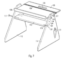
- the platen can also be used as a table by putting it in the horizontal position is pivoted (Fig. 7). It is then due to a screw existing stop 127 (Fig. 6). In this position, the platen 120 secured by the pin 122, which in a corresponding upper hole 124a (Fig. 6) the row of holes 124 is inserted.
- the pin 122 can by one on the adjacent Side part attached cord or chain (not shown) must be secured against loss.
- the platen 120 is provided with a grip hole 129 so that the accountant can be conveniently recorded and transported.
- a grip hole 129 To hold down the sides one on the Platen 120 lying book (not shown) is used in FIGS. 6 and 7 an annular Elastic band 138 which is slidable according to the size of the book.
- a pocket 131 for one can be on the outside of the side plate 114 Writing instrument must be attached.
- 6 and 7 can be delivered disassembled as a kit. To the You only need to assemble a screwdriver.
- Grip hole, elastic band, pen pocket and means for locking the Platen in the horizontal position can also according to the embodiment Fig. 1 find application.
Abstract
Description
Der Erfindung liegt die Aufgabe zugrunde, einen solchen Buchhalter zu schaffen.
- Fig. 1
- eine isometrische Darstellung einer ersten Ausführungsform des Buchhalters gemäß der Erfindung;
- Fig. 2
- eine Teilansicht eines im Gebrauch rechten Seitenteiles des Buchhalters gemäß Fig. 1 gesehen aus Richtung des im Gebrauch linken Seitenteils;
- Fig. 3
- eine Ansicht einer Anschlagvorrichtung des Buchhalters gemäß Fig. 1;
- Fig. 4
- eine Seitenansicht einer Vorrichtung zur schwenkbaren Lagerung einer Auflageplatte an einem Querstab des Buchhalters gemäß Fig. 1;
- Fig. 5
- eine alternative Lagerungsvorrichtung;
- Fig. 6
- eine isometrische, auseinandergezogene Darstellung einer zweiten, derzeit bevorzugten Ausführungsform der Erfindung; und
- Fig. 7
- ' eine perspektivische Ansicht des Buchhalters gemäß Fig. 6 mit horizontal eingestellter Auflageplatte..
Claims (10)
- Vorrichtung zum Haltern von Lesestoff, Schreibmaterial, eines Laptops u. a. m. mita) zwei plattenförmigen Seitenteilen [12, 14, 112, 114] aus Holzmaterial,b) einer die Seitenteile verbindenden und ein gegenseitiges Verdrehen der Seitenteile in Bezug aufeinander verhindernden Querstrebe [16, 116],c) einer bezüglich der Seitenteile schwenkbaren Auflageplatte [20, 120] aus Holzmaterial,d) einer Vorrichtung [16, 18; 116, 125] zum schwenkbaren Lagern der Auflageplatte an den Seitenteilen.e) einer Vorrichtung [22, 24, 122, 124] zur Einstellung verschiedener Winkelstellungen der Auflageplatte bezüglich der Seitenteile.
- Vorrichtung nach Anspruch 1, dadurch gekennzeichnet, dass die Querstrebe [16] ein Stab ist, an dem die Auflageplatte [20] schwenkbar gelagert ist [Fig. 1].
- Vorrichtung nach Anspruch 1, dadurch gekennzeichnet, dass die Querstrebe [115] ein plattenförmiges Bauteil ist [Fig. 6].
- Vorrichtung nach Anspruch 1, dadurch gekennzeichnet, dass die Vorrichtung zur schwenkbaren Lagerung der Auflageplatte [120] zwei als Wellenstummel wirkende Schrauben [125] enthält.
- Vorrichtung nach Anspruch 4, gekennzeichnet durch einen an der Auflageplatte befestigten Stab [116], in dem die Schrauben [125] sitzen.
- Vorrichtung nach Anspruch 1, dadurch gekennzeichnet, dass die Seitenteile [12, 14, 112, 114] zumindest in ihrem oberen Teil die Form von Trapezen haben.
- Vorrichtung nach Anspruch 1, gekennzeichnet durch Mittel [38, 40; 138] zum Niederhalten der Seiten des Lesestoffes.
- Vorrichtung nach Anspruch 7, dadurch gekennzeichnet, dass die Vorrichtung zum Niederhalten ein Gummiband [138] enthält.
- Vorrichtung nach Anspruch 1, dadurch gekennzeichnet, dass die Auflageplatte [120] ein Griffloch [129] aufweist.
- Vorrichtung nach Anspruch 1, dadurch gekennzeichnet, dass die Auflageplatte [20, 120] aus Sperrholz besteht.
Applications Claiming Priority (2)
| Application Number | Priority Date | Filing Date | Title |
|---|---|---|---|
| DE10003787A DE10003787A1 (de) | 2000-01-28 | 2000-01-28 | Buchhalter |
| DE10003787 | 2000-01-28 |
Publications (2)
| Publication Number | Publication Date |
|---|---|
| EP1120063A1 true EP1120063A1 (de) | 2001-08-01 |
| EP1120063B1 EP1120063B1 (de) | 2003-10-01 |
Family
ID=7629091
Family Applications (1)
| Application Number | Title | Priority Date | Filing Date |
|---|---|---|---|
| EP01101258A Expired - Lifetime EP1120063B1 (de) | 2000-01-28 | 2001-01-19 | Vorrichtung zum Haltern eines Lesestoffs bzw. Schreibmaterials |
Country Status (4)
| Country | Link |
|---|---|
| US (1) | US6425567B2 (de) |
| EP (1) | EP1120063B1 (de) |
| AT (1) | ATE250879T1 (de) |
| DE (3) | DE10003787A1 (de) |
Families Citing this family (25)
| Publication number | Priority date | Publication date | Assignee | Title |
|---|---|---|---|---|
| US6558596B1 (en) * | 1999-03-29 | 2003-05-06 | Gemtron Corporation | Method of molding a peripherally encapsulated product under heat and pressure utilizing sheet molding compound (SMC) or bulk molding compound (BMC) |
| JP2002346242A (ja) * | 2001-05-23 | 2002-12-03 | Aprica Kassai Inc | 遊戯具 |
| US6860458B1 (en) * | 2001-07-30 | 2005-03-01 | Samuel Pagano | Book holder |
| DE20118884U1 (de) | 2001-10-02 | 2002-02-07 | Cornelius Christian | Mit Füßen versehene, verschwenkbare Platte |
| JP2003159884A (ja) | 2001-11-27 | 2003-06-03 | Aprica Kassai Inc | 親子で綴る生命の記録帳および育児ユニット |
| US6712327B1 (en) * | 2002-10-08 | 2004-03-30 | Robert S. Carney, Jr. | Computer document holder |
| US7293784B2 (en) * | 2003-07-25 | 2007-11-13 | Ming-Tang Liu | Adjustable computer case support |
| TW200529351A (en) * | 2004-02-20 | 2005-09-01 | Innolux Display Corp | Assembling device for LCD module |
| US7523900B1 (en) * | 2005-06-13 | 2009-04-28 | Hlatky John D | Movable book and table holder |
| US20070007404A1 (en) * | 2005-07-08 | 2007-01-11 | Great Notions Corporation | Monitor stand |
| US20070012827A1 (en) * | 2005-07-15 | 2007-01-18 | Pinde Fu | Portable support device |
| US7677184B2 (en) * | 2005-12-15 | 2010-03-16 | Steelcase Development Corporation | Flip top table |
| US20070280043A1 (en) * | 2006-05-25 | 2007-12-06 | Antonio Cintorino | Device for holding mixing container during use |
| US20080106173A1 (en) * | 2006-11-07 | 2008-05-08 | Miles Anthony Konopka | Mobile data/audio/video/interactive presentation cart |
| US7887016B2 (en) * | 2007-08-23 | 2011-02-15 | Gunsaullus Scott E | All terrain material and tool tray |
| US7845611B1 (en) | 2007-11-16 | 2010-12-07 | Sholander Alfred M | Door operated page turner device, system and method for books |
| KR100943198B1 (ko) * | 2008-01-16 | 2010-02-19 | (주)삼미가구 | 각도 조절 용이성 및 지지안정성을 갖는 독서대 |
| US8100060B2 (en) * | 2008-03-31 | 2012-01-24 | Juan Chen | Dual-purpose table with revolving top |
| US7908978B1 (en) * | 2008-04-29 | 2011-03-22 | Pelton Jr Howard D | Computer gaming station |
| CN104273975A (zh) * | 2013-07-11 | 2015-01-14 | 张克营 | 一种多功能床 |
| USD804222S1 (en) * | 2015-06-26 | 2017-12-05 | Arnaud Leleu | Desk |
| CN105562599B (zh) * | 2015-12-15 | 2017-10-31 | 铜陵铜官府文化创意股份公司 | 制蜡石膏模放置装置 |
| US10492617B1 (en) * | 2017-06-24 | 2019-12-03 | David A. Macedo | Support apparatus for supporting a person's head above a mattress or other surface |
| US11478055B2 (en) * | 2020-03-12 | 2022-10-25 | Christopher Chatman | Mail carrier apparatus |
| US11490747B1 (en) * | 2022-01-05 | 2022-11-08 | Ten Square Inc | Magazine rack with building block base board |
Citations (10)
| Publication number | Priority date | Publication date | Assignee | Title |
|---|---|---|---|---|
| US1343229A (en) * | 1919-08-25 | 1920-06-15 | Jr Edward F Philbrook | Stand |
| US1652774A (en) * | 1923-03-16 | 1927-12-13 | Chelsea C Fraser | Desk |
| US1713376A (en) * | 1927-07-29 | 1929-05-14 | Durig Orval Gorby | Reading stand |
| US2741868A (en) * | 1954-05-28 | 1956-04-17 | Floyd E Saunders | Adjustable stand |
| US4108083A (en) * | 1977-05-04 | 1978-08-22 | Albert Espinosa | Portable writing and reading table assembly |
| US4383486A (en) * | 1980-07-28 | 1983-05-17 | Rol-Fol Table, Inc. | Desk for handicapped persons |
| US4466593A (en) * | 1981-03-02 | 1984-08-21 | Odenath Clayton P | Copyholder, lectern, book support |
| DE4321283A1 (de) * | 1993-06-26 | 1995-01-05 | Bruno Gruber | Tischpult |
| DE29715923U1 (de) * | 1997-09-05 | 1997-11-13 | Eugen Raible Fa | Pultartiger Schreibtisch, insbesondere Lernschreibtisch |
| DE19748793C1 (de) * | 1997-11-05 | 1999-08-12 | Werner Jelinek | Kompakt-Arbeitsplatz/Spielstation für handelsübliche PC-Systeme |
Family Cites Families (16)
| Publication number | Priority date | Publication date | Assignee | Title |
|---|---|---|---|---|
| US1645769A (en) * | 1926-04-06 | 1927-10-18 | Sarah L Murray | Combination desk and table |
| US1691191A (en) * | 1927-01-31 | 1928-11-13 | Ella C Henderson | Bookrack |
| US2006580A (en) * | 1935-02-18 | 1935-07-02 | Virginia M Broun | Portable reading desk |
| FR1600704A (de) * | 1968-12-31 | 1970-07-27 | ||
| US3682109A (en) * | 1970-07-20 | 1972-08-08 | Univ New York | Adjustable work table |
| US4022418A (en) * | 1976-02-09 | 1977-05-10 | Kellner Sam J | Reading stand |
| US4163539A (en) * | 1978-03-17 | 1979-08-07 | Awofolu Duke L | Reading table |
| DE8000787U1 (de) * | 1980-01-14 | 1980-04-17 | Team Form Ag, Hinwil (Schweiz) | Möbel mit verstellbarem Funktionselement |
| CA1126237A (en) * | 1980-12-17 | 1982-06-22 | Gillian Loban | Work holder for handicrafts |
| US4372631A (en) * | 1981-10-05 | 1983-02-08 | Leon Harry I | Foldable drafting table with drawers |
| US4512603A (en) * | 1983-02-01 | 1985-04-23 | Williams Tommy A | Book support system |
| USD293397S (en) * | 1985-06-17 | 1987-12-29 | Hunt William G | Adjustable table |
| US4943040A (en) * | 1989-01-26 | 1990-07-24 | Cannon Equipment Company | Adjustable work stand |
| USD341958S (en) * | 1991-09-12 | 1993-12-07 | Allred Charles C | Lap top desk |
| US5484124A (en) * | 1993-03-03 | 1996-01-16 | Billings; Donald | Non-tactual facilitation support system |
| US5601036A (en) * | 1995-04-13 | 1997-02-11 | Kieser; Joyce R. | Adjustable table |
-
2000
- 2000-01-28 DE DE10003787A patent/DE10003787A1/de not_active Withdrawn
-
2001
- 2001-01-19 DE DE20100986U patent/DE20100986U1/de not_active Expired - Lifetime
- 2001-01-19 EP EP01101258A patent/EP1120063B1/de not_active Expired - Lifetime
- 2001-01-19 AT AT01101258T patent/ATE250879T1/de not_active IP Right Cessation
- 2001-01-19 DE DE50100693T patent/DE50100693D1/de not_active Expired - Fee Related
- 2001-01-24 US US09/769,198 patent/US6425567B2/en not_active Expired - Fee Related
Patent Citations (10)
| Publication number | Priority date | Publication date | Assignee | Title |
|---|---|---|---|---|
| US1343229A (en) * | 1919-08-25 | 1920-06-15 | Jr Edward F Philbrook | Stand |
| US1652774A (en) * | 1923-03-16 | 1927-12-13 | Chelsea C Fraser | Desk |
| US1713376A (en) * | 1927-07-29 | 1929-05-14 | Durig Orval Gorby | Reading stand |
| US2741868A (en) * | 1954-05-28 | 1956-04-17 | Floyd E Saunders | Adjustable stand |
| US4108083A (en) * | 1977-05-04 | 1978-08-22 | Albert Espinosa | Portable writing and reading table assembly |
| US4383486A (en) * | 1980-07-28 | 1983-05-17 | Rol-Fol Table, Inc. | Desk for handicapped persons |
| US4466593A (en) * | 1981-03-02 | 1984-08-21 | Odenath Clayton P | Copyholder, lectern, book support |
| DE4321283A1 (de) * | 1993-06-26 | 1995-01-05 | Bruno Gruber | Tischpult |
| DE29715923U1 (de) * | 1997-09-05 | 1997-11-13 | Eugen Raible Fa | Pultartiger Schreibtisch, insbesondere Lernschreibtisch |
| DE19748793C1 (de) * | 1997-11-05 | 1999-08-12 | Werner Jelinek | Kompakt-Arbeitsplatz/Spielstation für handelsübliche PC-Systeme |
Also Published As
| Publication number | Publication date |
|---|---|
| US6425567B2 (en) | 2002-07-30 |
| DE50100693D1 (de) | 2003-11-06 |
| EP1120063B1 (de) | 2003-10-01 |
| US20010010351A1 (en) | 2001-08-02 |
| DE10003787A1 (de) | 2001-08-02 |
| DE20100986U1 (de) | 2001-03-29 |
| ATE250879T1 (de) | 2003-10-15 |
Similar Documents
| Publication | Publication Date | Title |
|---|---|---|
| EP1120063B1 (de) | Vorrichtung zum Haltern eines Lesestoffs bzw. Schreibmaterials | |
| DE1759642C3 (de) | Mehrfach verstellbares Scharnier | |
| DE3300647C2 (de) | ||
| DE202016000783U1 (de) | Möbelgestell | |
| DE473636C (de) | Klemmverbindung, insbesondere zum Festlegen des Fussbodens an einem festen Teil in Kraftwagen | |
| DE3002767C2 (de) | Berührungsschutzvorrichtung für eine Drallkeilspitze bei einer Vorrichtung zum Holzspalten | |
| DE7513254U (de) | Spannvorrichtung | |
| DE3118806A1 (de) | Halterung fuer ein hackbrett oder ein hackbrettaehnliches instrument | |
| DE3005173C2 (de) | Arbeitstisch | |
| DE3622823A1 (de) | Tisch mit verwandelbarer platte | |
| DE1952062A1 (de) | Zusammensetzbare Bauteilgruppe fuer Moebel und daraus hergestellte Moebel | |
| DE4206496A1 (de) | Bausatz fuer ausstellungs- und praesentationsstaende | |
| DE202021003239U1 (de) | Aufklappbarer Messerblock, arretierbar, als Tischprodukt und/oder Wandbefestigung | |
| DE202020106822U1 (de) | Ausziehtisch mit stabilisierten Ansatzplatten, insbesondere für den Außenbereich | |
| DE936652C (de) | Einrichtung zum Befestigen von Buegelbrettern verschiedener Groesse an einer Tischplatte | |
| DE2712925C3 (de) | Verbindung von Holzstreben, insbesondere für die Verwendung im Möbelbau | |
| DE1130976B (de) | Schreibtisch | |
| DE2329115A1 (de) | Moebelstueck mit fuessen, wie ein tisch, ein schreibtisch, ein kleintisch, ein stuhl, ein sessel (lehnstuhl) oder dgl | |
| DE3705145A1 (de) | Veraenderbarer tischaufsatz | |
| DE3536674A1 (de) | Bausatz fuer eine heimwerker-blechbiegevorrichtung | |
| CH106590A (de) | Einrichtung zum Halten von zu bearbeitenden Werkstücken. | |
| CH250674A (de) | Reissbrettstütze. | |
| DE4341654A1 (de) | Büromöbel | |
| DE1710073U (de) | Moebelstueck, insbesondere tisch. | |
| DE7922357U1 (de) | Buchstuetze |
Legal Events
| Date | Code | Title | Description |
|---|---|---|---|
| PUAI | Public reference made under article 153(3) epc to a published international application that has entered the european phase |
Free format text: ORIGINAL CODE: 0009012 |
|
| AK | Designated contracting states |
Kind code of ref document: A1 Designated state(s): AT BE CH CY DE DK ES FI FR GB GR IE IT LI LU MC NL PT SE TR |
|
| AX | Request for extension of the european patent |
Free format text: AL;LT;LV;MK;RO;SI |
|
| 17P | Request for examination filed |
Effective date: 20020117 |
|
| AKX | Designation fees paid |
Free format text: AT BE CH CY DE DK ES FI FR GB GR IE IT LI LU MC NL PT SE TR |
|
| 17Q | First examination report despatched |
Effective date: 20020722 |
|
| GRAH | Despatch of communication of intention to grant a patent |
Free format text: ORIGINAL CODE: EPIDOS IGRA |
|
| GRAS | Grant fee paid |
Free format text: ORIGINAL CODE: EPIDOSNIGR3 |
|
| GRAA | (expected) grant |
Free format text: ORIGINAL CODE: 0009210 |
|
| AK | Designated contracting states |
Kind code of ref document: B1 Designated state(s): AT BE CH CY DE DK ES FI FR GB GR IE IT LI LU MC NL PT SE TR |
|
| PG25 | Lapsed in a contracting state [announced via postgrant information from national office to epo] |
Ref country code: TR Free format text: LAPSE BECAUSE OF FAILURE TO SUBMIT A TRANSLATION OF THE DESCRIPTION OR TO PAY THE FEE WITHIN THE PRESCRIBED TIME-LIMIT Effective date: 20031001 Ref country code: NL Free format text: LAPSE BECAUSE OF FAILURE TO SUBMIT A TRANSLATION OF THE DESCRIPTION OR TO PAY THE FEE WITHIN THE PRESCRIBED TIME-LIMIT Effective date: 20031001 Ref country code: IT Free format text: LAPSE BECAUSE OF FAILURE TO SUBMIT A TRANSLATION OF THE DESCRIPTION OR TO PAY THE FEE WITHIN THE PRESCRIBED TIME-LIMIT;WARNING: LAPSES OF ITALIAN PATENTS WITH EFFECTIVE DATE BEFORE 2007 MAY HAVE OCCURRED AT ANY TIME BEFORE 2007. THE CORRECT EFFECTIVE DATE MAY BE DIFFERENT FROM THE ONE RECORDED. Effective date: 20031001 Ref country code: IE Free format text: LAPSE BECAUSE OF FAILURE TO SUBMIT A TRANSLATION OF THE DESCRIPTION OR TO PAY THE FEE WITHIN THE PRESCRIBED TIME-LIMIT Effective date: 20031001 Ref country code: FI Free format text: LAPSE BECAUSE OF FAILURE TO SUBMIT A TRANSLATION OF THE DESCRIPTION OR TO PAY THE FEE WITHIN THE PRESCRIBED TIME-LIMIT Effective date: 20031001 Ref country code: CY Free format text: LAPSE BECAUSE OF FAILURE TO SUBMIT A TRANSLATION OF THE DESCRIPTION OR TO PAY THE FEE WITHIN THE PRESCRIBED TIME-LIMIT Effective date: 20031001 |
|
| REG | Reference to a national code |
Ref country code: GB Ref legal event code: FG4D Free format text: NOT ENGLISH |
|
| REG | Reference to a national code |
Ref country code: CH Ref legal event code: EP |
|
| REG | Reference to a national code |
Ref country code: IE Ref legal event code: FG4D Free format text: GERMAN |
|
| REF | Corresponds to: |
Ref document number: 50100693 Country of ref document: DE Date of ref document: 20031106 Kind code of ref document: P |
|
| PG25 | Lapsed in a contracting state [announced via postgrant information from national office to epo] |
Ref country code: SE Free format text: LAPSE BECAUSE OF FAILURE TO SUBMIT A TRANSLATION OF THE DESCRIPTION OR TO PAY THE FEE WITHIN THE PRESCRIBED TIME-LIMIT Effective date: 20040101 Ref country code: GR Free format text: LAPSE BECAUSE OF FAILURE TO SUBMIT A TRANSLATION OF THE DESCRIPTION OR TO PAY THE FEE WITHIN THE PRESCRIBED TIME-LIMIT Effective date: 20040101 Ref country code: DK Free format text: LAPSE BECAUSE OF FAILURE TO SUBMIT A TRANSLATION OF THE DESCRIPTION OR TO PAY THE FEE WITHIN THE PRESCRIBED TIME-LIMIT Effective date: 20040101 |
|
| PG25 | Lapsed in a contracting state [announced via postgrant information from national office to epo] |
Ref country code: ES Free format text: LAPSE BECAUSE OF FAILURE TO SUBMIT A TRANSLATION OF THE DESCRIPTION OR TO PAY THE FEE WITHIN THE PRESCRIBED TIME-LIMIT Effective date: 20040112 |
|
| PG25 | Lapsed in a contracting state [announced via postgrant information from national office to epo] |
Ref country code: LU Free format text: LAPSE BECAUSE OF NON-PAYMENT OF DUE FEES Effective date: 20040119 Ref country code: AT Free format text: LAPSE BECAUSE OF NON-PAYMENT OF DUE FEES Effective date: 20040119 |
|
| GBT | Gb: translation of ep patent filed (gb section 77(6)(a)/1977) |
Effective date: 20040103 |
|
| PGFP | Annual fee paid to national office [announced via postgrant information from national office to epo] |
Ref country code: FR Payment date: 20040130 Year of fee payment: 4 |
|
| PG25 | Lapsed in a contracting state [announced via postgrant information from national office to epo] |
Ref country code: MC Free format text: LAPSE BECAUSE OF NON-PAYMENT OF DUE FEES Effective date: 20040131 Ref country code: BE Free format text: LAPSE BECAUSE OF NON-PAYMENT OF DUE FEES Effective date: 20040131 |
|
| NLV1 | Nl: lapsed or annulled due to failure to fulfill the requirements of art. 29p and 29m of the patents act | ||
| REG | Reference to a national code |
Ref country code: IE Ref legal event code: FD4D |
|
| ET | Fr: translation filed | ||
| BERE | Be: lapsed |
Owner name: *SCHUTZE CHRISTIAN Effective date: 20040131 |
|
| PLBE | No opposition filed within time limit |
Free format text: ORIGINAL CODE: 0009261 |
|
| STAA | Information on the status of an ep patent application or granted ep patent |
Free format text: STATUS: NO OPPOSITION FILED WITHIN TIME LIMIT |
|
| 26N | No opposition filed |
Effective date: 20040702 |
|
| PG25 | Lapsed in a contracting state [announced via postgrant information from national office to epo] |
Ref country code: GB Free format text: LAPSE BECAUSE OF NON-PAYMENT OF DUE FEES Effective date: 20050119 |
|
| PG25 | Lapsed in a contracting state [announced via postgrant information from national office to epo] |
Ref country code: LI Free format text: LAPSE BECAUSE OF NON-PAYMENT OF DUE FEES Effective date: 20050131 Ref country code: CH Free format text: LAPSE BECAUSE OF NON-PAYMENT OF DUE FEES Effective date: 20050131 |
|
| GBPC | Gb: european patent ceased through non-payment of renewal fee |
Effective date: 20050119 |
|
| REG | Reference to a national code |
Ref country code: CH Ref legal event code: PL |
|
| PG25 | Lapsed in a contracting state [announced via postgrant information from national office to epo] |
Ref country code: FR Free format text: LAPSE BECAUSE OF NON-PAYMENT OF DUE FEES Effective date: 20050930 |
|
| REG | Reference to a national code |
Ref country code: FR Ref legal event code: ST |
|
| PGFP | Annual fee paid to national office [announced via postgrant information from national office to epo] |
Ref country code: DE Payment date: 20070726 Year of fee payment: 7 |
|
| PG25 | Lapsed in a contracting state [announced via postgrant information from national office to epo] |
Ref country code: PT Free format text: LAPSE BECAUSE OF NON-PAYMENT OF DUE FEES Effective date: 20040301 |
|
| PG25 | Lapsed in a contracting state [announced via postgrant information from national office to epo] |
Ref country code: DE Free format text: LAPSE BECAUSE OF NON-PAYMENT OF DUE FEES Effective date: 20080801 |