EP1120631A1 - Navigation device - Google Patents
Navigation device Download PDFInfo
- Publication number
- EP1120631A1 EP1120631A1 EP99926964A EP99926964A EP1120631A1 EP 1120631 A1 EP1120631 A1 EP 1120631A1 EP 99926964 A EP99926964 A EP 99926964A EP 99926964 A EP99926964 A EP 99926964A EP 1120631 A1 EP1120631 A1 EP 1120631A1
- Authority
- EP
- European Patent Office
- Prior art keywords
- tunnel
- vehicle
- mode function
- vehicle speed
- navigation device
- Prior art date
- Legal status (The legal status is an assumption and is not a legal conclusion. Google has not performed a legal analysis and makes no representation as to the accuracy of the status listed.)
- Granted
Links
Images


Classifications
-
- B—PERFORMING OPERATIONS; TRANSPORTING
- B60—VEHICLES IN GENERAL
- B60H—ARRANGEMENTS OF HEATING, COOLING, VENTILATING OR OTHER AIR-TREATING DEVICES SPECIALLY ADAPTED FOR PASSENGER OR GOODS SPACES OF VEHICLES
- B60H1/00—Heating, cooling or ventilating [HVAC] devices
- B60H1/00642—Control systems or circuits; Control members or indication devices for heating, cooling or ventilating devices
- B60H1/00735—Control systems or circuits characterised by their input, i.e. by the detection, measurement or calculation of particular conditions, e.g. signal treatment, dynamic models
- B60H1/00764—Control systems or circuits characterised by their input, i.e. by the detection, measurement or calculation of particular conditions, e.g. signal treatment, dynamic models the input being a vehicle driving condition, e.g. speed
- B60H1/00771—Control systems or circuits characterised by their input, i.e. by the detection, measurement or calculation of particular conditions, e.g. signal treatment, dynamic models the input being a vehicle driving condition, e.g. speed the input being a vehicle position or surrounding, e.g. GPS-based position or tunnel
-
- G—PHYSICS
- G01—MEASURING; TESTING
- G01C—MEASURING DISTANCES, LEVELS OR BEARINGS; SURVEYING; NAVIGATION; GYROSCOPIC INSTRUMENTS; PHOTOGRAMMETRY OR VIDEOGRAMMETRY
- G01C21/00—Navigation; Navigational instruments not provided for in groups G01C1/00 - G01C19/00
- G01C21/26—Navigation; Navigational instruments not provided for in groups G01C1/00 - G01C19/00 specially adapted for navigation in a road network
- G01C21/34—Route searching; Route guidance
- G01C21/36—Input/output arrangements for on-board computers
- G01C21/3626—Details of the output of route guidance instructions
- G01C21/3644—Landmark guidance, e.g. using POIs or conspicuous other objects
-
- G—PHYSICS
- G01—MEASURING; TESTING
- G01C—MEASURING DISTANCES, LEVELS OR BEARINGS; SURVEYING; NAVIGATION; GYROSCOPIC INSTRUMENTS; PHOTOGRAMMETRY OR VIDEOGRAMMETRY
- G01C21/00—Navigation; Navigational instruments not provided for in groups G01C1/00 - G01C19/00
- G01C21/26—Navigation; Navigational instruments not provided for in groups G01C1/00 - G01C19/00 specially adapted for navigation in a road network
- G01C21/34—Route searching; Route guidance
- G01C21/36—Input/output arrangements for on-board computers
- G01C21/3697—Output of additional, non-guidance related information, e.g. low fuel level
Definitions
- the present invention relates to a navigation device which indicates the characteristics of a tunnel on the display before entering the tunnel when a vehicle's approach to the tunnel is detected using a navigation function.
- the safety and comfort of the driver are maintained by displaying a precaution with respect to conditions resulting from entering the tunnel.
- Fig. 1 shows a conventional navigation device as disclosed for example in JP-A-10-100815.
- the navigation device is adapted to detect a vehicle's approach to a tunnel and activate various on-vehicle devices in a tunnel mode function on the basis of the detected signal.
- reference numeral 1 denotes a navigation computer means with a database (not shown). Map data is stored in the database, the map data includes data on the accurate position of tunnels as well as data on a road network, which can be travelled on by the vehicle, and the road network surroundings.
- 2 is a GPS antenna
- 3 is a vehicle position detection means
- 4 is a control means which controls the operation of the on-vehicle devices based on the output signal from the navigation computer means 1.
- 5 is a window operation means provided with a motor
- 6 is a headlight control means
- 7 is a sunroof operation means
- 8 is an air conditioner switching means which switches an air circulation mode
- 9 is a manual tunnel switch for controlling the activation of each means manually based on the display command from the control means 4 with respect to the tunnel mode function.
- the navigation computer means 1 determines a vehicle position continuously on a road network on the basis of a GPS satellite signal from a GPS antenna and an output signal of the vehicle position detection means 3. From the continuously obtained position, the navigation computer means 1 confirms whether the vehicle is currently traveling inside or outside a tunnel on a searched route. If the vehicle is currently inside a tunnel, the navigation computer means 1 confirms whether the vehicle has just entered the tunnel or has just finished travelling through the tunnel.
- an appropriate message signal is transmitted to the control means 4.
- the control means 4 selects on-vehicle devices to be activated in a tunnel mode function in response to the transmitted signal and automatically activates the tunnel mode function.
- a display suggesting operation of the manual tunnel switch 9 is performed.
- a driver operates the manual tunnel switch 9 based on this display and various types of on-vehicle equipment are activated in the tunnel mode function.
- such a tunnel mode function includes,
- the conventional navigation device is constructed as the above, on-vehicle devices are activated in a tunnel mode function or are placed in an operable state for the tunnel mode function if it is confirmed that a vehicle will enter a tunnel on a currently traveled searched route.
- various on-vehicle devices are switched intermittently between the tunnel mode and the other modes.
- the problem has arisen that even when the tunnel mode function is activated, since information such as the length of the tunnel, lane number, presence of traffic signals in the tunnel is not known, the driver has to enter the tunnel in a tense, uneasy state.
- the inside of the tunnel is sloping and the road extends in a descending slope towards the tunnel exit, vehicle speed will naturally increase.
- the road curves at the tunnel exit the possibility exists of dangerous conditions.
- the present invention is proposed to solve the above problems and has the object of providing a navigation device which performs a precautionary function by informing characteristics of a tunnel to a driver before entering the tunnel when a vehicle encounters a tunnel.
- characteristics include for example, the name of the tunnel, the shape of the tunnel (length, height, width, presence of curves), the lane number, and the presence of traffic lights or the like.
- the navigation device comprises: a vehicle position detection means for detecting a vehicle position; a vehicle speed detection means for detecting a vehicle speed; a determination means provided with a database which records data on a currently traveled route network, data on the surroundings thereof, and characteristic data relating to tunnels on the route network, the determination means determining whether or not to activate a tunnel mode function on the basis of the characteristic data relating to the tunnel read from the database, the vehicle speed detected by the vehicle speed detection means and the vehicle position detected by the vehicle position detection means; and a control means for displaying characteristics of the tunnel to be travelled through on a display means based on a command signal from the determination means indicative of activation of the tunnel mode function and for activating each on-vehicle device in the tunnel mode function or suggesting activation of the tunnel mode function.
- the navigation device of the present invention is adapted to determine whether to activate a tunnel mode function in consideration of the vehicle speed and the displayed information about the tunnel, and to automatically activate various on-vehicle devices in the tunnel mode function or display the suggestion to activate the tunnel mode function in order to instruct a driver to operate the manual tunnel switch.
- the navigation device of the present invention may be adapted to display a longitudinal sectional view of the tunnel through which the vehicle will travel on a display section of the navigation means when the tunnel mode function is activated.
- the navigation device of the present invention may be adapted to display characteristic information relating to the tunnel through which the vehicle will travel on a display section of the navigation means.
- the navigation device of the present invention is adapted to calculate a distance to a tunnel based on a vehicle speed detected by a vehicle speed detection means when the vehicle lies within a link area in map data on which the tunnel exists.
- a distance to a tunnel based on a vehicle speed detected by a vehicle speed detection means when the vehicle lies within a link area in map data on which the tunnel exists.
- the navigation device of the present invention may be adapted to determine whether or not to guide a tunnel based on the tunnel length and an average vehicle speed before entering the tunnel.
- Fig. 2 is a block diagram schematically showing the configuration of a navigation device according to a first embodiment of the present invention.
- reference numeral 11 denotes a GPS antenna
- 12 is an automatic vehicle position detection means which detects a vehicle position based on a received signal from the GPS antenna 11.
- 13 is a determination means which has a database which stores data on a currently traveled route network, data on the surroundings thereof, and characteristic data relating to tunnels on a route network. The determination means 13 determines whether or not to activate a tunnel mode function based on the characteristic data relating to the tunnel read from the database, the vehicle speed detected by the vehicle speed detection means 14 and the vehicle position detected by the vehicle position detection means 12.
- the determination of when to display the tunnel through which the vehicle will travel is performed based on the following procedure. For example, when a tunnel exists on a travel route to be displayed on a map and the vehicle enters the link area on which the tunnel exists, a distance to the tunnel is calculated in consideration of the vehicle speed detected by the vehicle speed detection means. Then, if the distance is not more than a pre-set fixed value, characteristics of the tunnel and a longitudinal section of the tunnel 22 in the direction of travel as shown in Fig. 4 are displayed.
- the tunnel characteristics include, for example, the name of the tunnel, the shape of the tunnel (height, width, length, presence of curves), the lane number in the tunnel, the presence of a plurality of tunnels in a short distance (hereafter this is termed "continuous tunnel", that is to say, when there is a single short tunnel, the possibility exists that it is not necessary to switch to a tunnel mode function and when a plurality of tunnels continues, it will be often the case that the device should be switched to the tunnel mode function), the presence of traffic lights in the tunnel or the like.
- sudden information related to traffic congestion and the presence of traffic restrictions is displayed on the display means 16.
- the position of fire extinguishing valves 22a, the position of emergency exits 22b as well as the maximum angle of slope, the length and name of the tunnel may be added as shown in Fig. 5.
- the tunnel may be displayed in a deformation 3-D presentation.
- 17 denotes a window operation means which opens and closes a door window
- 18 is a headlight control means which operates the beam of the headlights
- 19 is a sunroof operation means which opens and closes the sunroof
- 20 is an air conditioner switching means which switches an air conditioner mode
- 21 is a manual tunnel switch which activates each means manually in the tunnel mode function when the activation of the tunnel mode function is displayed by the determination of the central control means.
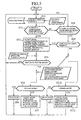
- Fig. 3 is a flowchart showing the operation of the navigation device.
- the vehicle position detection means 12 receives a GPS signal through the GPS antenna 11, reads data on a route network from a database and specifies a vehicle position on the route network (step ST1).
- the determination means 13 determines whether a tunnel is approaching based on a signal indicative of the vehicle position specified as above and the vehicle speed detected by the vehicle detection means 14 (step ST2). If the answer is "Yes", the control means 15 receives a determination signal from the determination means 13 and displays characteristics of the tunnel on the display means 16 (step ST3). Then, it is determined whether it is necessary to switch the various on-vehicle devices to the tunnel mode function in consideration of current average vehicle speed, tunnel length and the like (step ST4).
- control means 15 effects the following operations.
- the switching may be performed manually by operation of the manual tunnel switch 21 based on a command display indicating that switching of the various on-vehicle devices to the tunnel mode function should be performed.
- step ST5 it is determined whether the state of the vehicle is in the tunnel mode function. If the result of the determination is "Yes”, no action is taken (step ST6). If the answer is "No”, the tunnel mode function is automatically activated or suggestion to activate the tunnel mode function is given by voice command or display (step ST7).
- a method of activating the tunnel mode function there are some methods such as an automatic activation method (in view of safety considerations), manual activation method by operation of the manual tunnel switch 21 provided in the vehicle, and a method of suggesting activation of the tunnel mode function to the driver by audio-visual instruction.
- step ST2 determines whether or not the vehicle will exit the tunnel soon.
- step ST8 determines whether or not the vehicle will exit the tunnel soon.
- step ST9 determines whether or not a continuous tunnel exists. If the answer is "Yes”, the routine returns to the step ST3 and the tunnel characteristics are displayed. If the answer is "No”, the routine performs the opposite operation to (1) to (5) above. That is to say:
- step ST10 it is determined whether the vehicle is in the tunnel mode function. If the result of the determination is "No”, no action is taken (step ST11). If the result of the determination is "Yes”, the tunnel mode function is automatically deactivated or suggestion to deactivate the tunnel mode function is given by voice command or display (step ST12). Deactivation of the tunnel mode function is effected in the same manner as activation of the tunnel mode function as discussed above, the on-vehicle devices are returned to the state immediately before activating the tunnel mode function.
- suggestion to the driver may be given by voice commands.
- Unnecessary tunnel guiding can be prevented by performing a determination as to whether the tunnel mode function should be activated, based on the distance to the tunnel and the vehicle speed.
- the tunnel mode function should be activated.
- tunnel characteristics such as, for example, the name of the tunnel, the shape of the tunnel (height, width, length, presence of curves), the lane number in the tunnel, the presence of a plurality of tunnels in a short distance (hereafter this is termed "continuous tunnel", that is to say, when there is a single short tunnel, the possibility exists that it is not necessary to switch to the tunnel mode function, but when a plurality of tunnels continues, it will be often the case that the device should be switched to the tunnel mode function), the presence of traffic lights in the tunnel or the like are displayed.
- a longitudinal cross section of the tunnel 22 in the direction of travel is also displayed.
- the navigation device is adapted to indicate tunnel conditions in a tunnel which will be travelled through to the driver beforehand by indication of the tunnel characteristics when the vehicle approaches the tunnel on a travel route is approaching, and thus to increase driving safety and comfort due to the extra time allowed for driving.
Abstract
Description
- The present invention relates to a navigation device which indicates the characteristics of a tunnel on the display before entering the tunnel when a vehicle's approach to the tunnel is detected using a navigation function. The safety and comfort of the driver are maintained by displaying a precaution with respect to conditions resulting from entering the tunnel.
- Fig. 1 shows a conventional navigation device as disclosed for example in JP-A-10-100815. The navigation device is adapted to detect a vehicle's approach to a tunnel and activate various on-vehicle devices in a tunnel mode function on the basis of the detected signal.
- In Fig. 1,
reference numeral 1 denotes a navigation computer means with a database (not shown). Map data is stored in the database, the map data includes data on the accurate position of tunnels as well as data on a road network, which can be travelled on by the vehicle, and the road network surroundings. - 2 is a GPS antenna, 3 is a vehicle position detection means, 4 is a control means which controls the operation of the on-vehicle devices based on the output signal from the navigation computer means 1. 5 is a window operation means provided with a motor, 6 is a headlight control means, 7 is a sunroof operation means, 8 is an air conditioner switching means which switches an air circulation mode, 9 is a manual tunnel switch for controlling the activation of each means manually based on the display command from the control means 4 with respect to the tunnel mode function.
- Next, the operation of the conventional navigation device will be described.
- The navigation computer means 1 determines a vehicle position continuously on a road network on the basis of a GPS satellite signal from a GPS antenna and an output signal of the vehicle position detection means 3. From the continuously obtained position, the navigation computer means 1 confirms whether the vehicle is currently traveling inside or outside a tunnel on a searched route. If the vehicle is currently inside a tunnel, the navigation computer means 1 confirms whether the vehicle has just entered the tunnel or has just finished travelling through the tunnel.
- When it is determined that the vehicle is about to enter the tunnel, an appropriate message signal is transmitted to the control means 4. The control means 4 selects on-vehicle devices to be activated in a tunnel mode function in response to the transmitted signal and automatically activates the tunnel mode function. Alternatively, a display suggesting operation of the
manual tunnel switch 9 is performed. A driver operates themanual tunnel switch 9 based on this display and various types of on-vehicle equipment are activated in the tunnel mode function. - For example, such a tunnel mode function includes,
- (1) Closing the windows by activation of the window operation means 5,
- (2) Closing the sunroof by activation of the sunroof operation means 7,
- (3) Activating the headlight control means 6 to lower the beam of the headlights for example,
- (4) Placing the air-conditioner in air recirculation mode by activation of the air-conditioner switching means 8,
- (5) Switching over an audio system from radio reception mode to recorded medium mode.
-
- Since the conventional navigation device is constructed as the above, on-vehicle devices are activated in a tunnel mode function or are placed in an operable state for the tunnel mode function if it is confirmed that a vehicle will enter a tunnel on a currently traveled searched route. However, for example even in those cases when the tunnel is short and it is not necessarily required to activate the tunnel mode function or place the on-vehicle devices in an operable state for the tunnel mode function, various on-vehicle devices are switched intermittently between the tunnel mode and the other modes. Thus, the possibility exists that the durability of the on-vehicle devices will be reduced as a result of the frequent switching operation.
- Furthermore, the problem has arisen that even when the tunnel mode function is activated, since information such as the length of the tunnel, lane number, presence of traffic signals in the tunnel is not known, the driver has to enter the tunnel in a tense, uneasy state. In particular, if the inside of the tunnel is sloping and the road extends in a descending slope towards the tunnel exit, vehicle speed will naturally increase. Furthermore, when the road curves at the tunnel exit, the possibility exists of dangerous conditions.
- Thus, the present invention is proposed to solve the above problems and has the object of providing a navigation device which performs a precautionary function by informing characteristics of a tunnel to a driver before entering the tunnel when a vehicle encounters a tunnel. Such characteristics include for example, the name of the tunnel, the shape of the tunnel (length, height, width, presence of curves), the lane number, and the presence of traffic lights or the like.
- The navigation device according to the present invention comprises: a vehicle position detection means for detecting a vehicle position; a vehicle speed detection means for detecting a vehicle speed; a determination means provided with a database which records data on a currently traveled route network, data on the surroundings thereof, and characteristic data relating to tunnels on the route network, the determination means determining whether or not to activate a tunnel mode function on the basis of the characteristic data relating to the tunnel read from the database, the vehicle speed detected by the vehicle speed detection means and the vehicle position detected by the vehicle position detection means; and a control means for displaying characteristics of the tunnel to be travelled through on a display means based on a command signal from the determination means indicative of activation of the tunnel mode function and for activating each on-vehicle device in the tunnel mode function or suggesting activation of the tunnel mode function.
- In this way, when a vehicle approaches a tunnel, the characteristics of the tunnel are indicated on the display section of the navigation device and it is possible to comprehend the characteristic conditions of the tunnel beforehand. As a result, the decisions whether to illuminate headlights, turn off wipers, close windows, and switch the air-conditioner to air recirculation mode can be performed with a degree of ease. Thus, driving comfort and driving safety are increased.
- Further, the navigation device of the present invention is adapted to determine whether to activate a tunnel mode function in consideration of the vehicle speed and the displayed information about the tunnel, and to automatically activate various on-vehicle devices in the tunnel mode function or display the suggestion to activate the tunnel mode function in order to instruct a driver to operate the manual tunnel switch. As a result, it is possible to avoid unnecessary mode switching in comparison with the conventional navigation device which switches the mode of the on-vehicle devices on each occasion to enter a tunnel. Therefore, damage due to frequent mode switching of various on-vehicle devices can be reduced
- The navigation device of the present invention may be adapted to display a longitudinal sectional view of the tunnel through which the vehicle will travel on a display section of the navigation means when the tunnel mode function is activated.
- In such a way, it is possible to indicate a slope of the road in the tunnel. Thus, it is possible to drive according to the road conditions, as a result, driving safety can be improved.
- The navigation device of the present invention may be adapted to display characteristic information relating to the tunnel through which the vehicle will travel on a display section of the navigation means.
- In such a way, it is possible to indicate tunnel conditions to the driver beforehand. Therefore, it is possible to improve driving safety and comfort as a result of the extra time allowed for determining required actions.
- Furthermore, the navigation device of the present invention is adapted to calculate a distance to a tunnel based on a vehicle speed detected by a vehicle speed detection means when the vehicle lies within a link area in map data on which the tunnel exists. When the distance is within a fixed value, characteristics relating to the tunnel through which the vehicle will travel are displayed on the display section of the navigation means.
- In such a way, it is possible to perform display of tunnel characteristics in an appropriate timeframe in consideration of vehicle speed.
- The navigation device of the present invention may be adapted to determine whether or not to guide a tunnel based on the tunnel length and an average vehicle speed before entering the tunnel.
- In such a way, it is possible to prevent unnecessary tunnel guiding.
-
- Fig. 1 is a block diagram showing the state in which a conventional navigation device is used.
- Fig. 2 is a block diagram showing the state in which a navigation device according to the present invention is used.
- Fig. 3 is a flowchart showing the operation of the navigation device according to the present invention.
- Fig. 4 is a longitudinal section of a tunnel displayed when in tunnel mode function.
- Fig. 5 shows the state in a tunnel.
- Fig. 6 shows a tunnel in three dimensions.
-
- In order to describe the invention is greater detail, the preferred embodiments of the invention will be described below with reference to the accompanying drawings.
- Fig. 2 is a block diagram schematically showing the configuration of a navigation device according to a first embodiment of the present invention. In the figure, reference numeral 11 denotes a GPS antenna, 12 is an automatic vehicle position detection means which detects a vehicle position based on a received signal from the GPS antenna 11. 13 is a determination means which has a database which stores data on a currently traveled route network, data on the surroundings thereof, and characteristic data relating to tunnels on a route network. The determination means 13 determines whether or not to activate a tunnel mode function based on the characteristic data relating to the tunnel read from the database, the vehicle speed detected by the vehicle speed detection means 14 and the vehicle position detected by the vehicle position detection means 12.
- When a vehicle approaches a tunnel, the determination of when to display the tunnel through which the vehicle will travel is performed based on the following procedure. For example, when a tunnel exists on a travel route to be displayed on a map and the vehicle enters the link area on which the tunnel exists, a distance to the tunnel is calculated in consideration of the vehicle speed detected by the vehicle speed detection means. Then, if the distance is not more than a pre-set fixed value, characteristics of the tunnel and a longitudinal section of the
tunnel 22 in the direction of travel as shown in Fig. 4 are displayed. The tunnel characteristics include, for example, the name of the tunnel, the shape of the tunnel (height, width, length, presence of curves), the lane number in the tunnel, the presence of a plurality of tunnels in a short distance (hereafter this is termed "continuous tunnel", that is to say, when there is a single short tunnel, the possibility exists that it is not necessary to switch to a tunnel mode function and when a plurality of tunnels continues, it will be often the case that the device should be switched to the tunnel mode function), the presence of traffic lights in the tunnel or the like. In addition, sudden information related to traffic congestion and the presence of traffic restrictions is displayed on the display means 16. - Apart from the longitudinal cross section of the tunnel as shown in Fig. 4, the position of
fire extinguishing valves 22a, the position of emergency exits 22b as well as the maximum angle of slope, the length and name of the tunnel may be added as shown in Fig. 5. - Further, as shown in Fig. 6, the tunnel may be displayed in a deformation 3-D presentation.
- Furthermore, by displaying the present position of the vehicle on the tunnel map, a user can easily discern the remaining distance in the tunnel.
- 17 denotes a window operation means which opens and closes a door window, 18 is a headlight control means which operates the beam of the headlights, 19 is a sunroof operation means which opens and closes the sunroof, 20 is an air conditioner switching means which switches an air conditioner mode, 21 is a manual tunnel switch which activates each means manually in the tunnel mode function when the activation of the tunnel mode function is displayed by the determination of the central control means.
- Next, the operation of the navigation device according to the present invention will be described.
- Fig. 3 is a flowchart showing the operation of the navigation device. Firstly, the vehicle position detection means 12 receives a GPS signal through the GPS antenna 11, reads data on a route network from a database and specifies a vehicle position on the route network (step ST1).
- The determination means 13 determines whether a tunnel is approaching based on a signal indicative of the vehicle position specified as above and the vehicle speed detected by the vehicle detection means 14 (step ST2). If the answer is "Yes", the control means 15 receives a determination signal from the determination means 13 and displays characteristics of the tunnel on the display means 16 (step ST3). Then, it is determined whether it is necessary to switch the various on-vehicle devices to the tunnel mode function in consideration of current average vehicle speed, tunnel length and the like (step ST4).
- If the result of the determination is "Yes", that is to say, when it is necessary to switch the devices to the tunnel mode function, the control means 15 effects the following operations.
- (1) The state of the headlights is detected. When the state of the headlights detected is OFF, either the driver is advised to turn the headlights ON or the headlight control means 18 is activated to automatically turn the headlights ON. Further, in order to improve visibility in the tunnel for the driver, the brightness of the headlights and beam height as well as the color tone of the display may be adjusted.
- (2) The state of the windows is detected and when the window are in an open position, the window operation means 17 is activated and the windows are closed.
- (3) The state of the sunroof is detected and when the sunroof is in an open position, the sunroof operation means 19 is activated and the sunroof is closed.
- (4) The state of the internal/external air recirculation is detected and when external air recirculation is performed before entry into a tunnel, the user is advised to switch to internal air recirculation mode or the air-conditioning switch means 20 is activated to automatically switch the air-conditioning system to internal air recirculation mode. In addition,
- (5) Radio or TV stations which can be received in the tunnel are displayed so that the driver can perform tuning. Otherwise, the tuning may be automatically performed. If no stations can be received or when noise interference is severe, the device is adapted to switch automatically to other audio devices or to automatically apply a mute.
-
- Apart from performing such switching automatically, the switching may be performed manually by operation of the
manual tunnel switch 21 based on a command display indicating that switching of the various on-vehicle devices to the tunnel mode function should be performed. - Next, it is determined whether the state of the vehicle is in the tunnel mode function (step ST5). If the result of the determination is "Yes", no action is taken (step ST6). If the answer is "No", the tunnel mode function is automatically activated or suggestion to activate the tunnel mode function is given by voice command or display (step ST7). As a method of activating the tunnel mode function, there are some methods such as an automatic activation method (in view of safety considerations), manual activation method by operation of the
manual tunnel switch 21 provided in the vehicle, and a method of suggesting activation of the tunnel mode function to the driver by audio-visual instruction. - On the other hand, if the determination result in step ST2 is "No", it is determined whether or not the vehicle will exit the tunnel soon (step ST8). When the answer is "No", the routine returns to the step ST1 and the operation as described above is repeated. When the answer is "Yes", it is determined from data read from the database whether or not a continuous tunnel exists (step ST9). If the answer is "Yes", the routine returns to the step ST3 and the tunnel characteristics are displayed. If the answer is "No", the routine performs the opposite operation to (1) to (5) above. That is to say:
- (1) The state of the headlights is detected. When the state of the headlights is ON after the vehicle exits the tunnel, either the driver is advised to turn the headlights OFF or the headlight control means 18 is activated to automatically turn the headlights OFF. Further, the brightness of the headlights and beam height as well as the color tone of the display are returned to the previous state.
- (2) The state of the windows is detected and when the windows are in a closed position, the window operation means 17 is activated to open the windows if necessary.
- (3) The state of the sunroof is detected and when the sunroof is in a closed position, the sunroof operation means 19 is activated to open the sunroof, if necessary.
- (4) The state of the internal/external air recirculation is detected and when internal air recirculation is performed after exiting the tunnel, the user is advised to switch to external air recirculation mode or the air-conditioning switch means 17 is activated to automatically switch the air-conditioning system to external air recirculation mode. In addition,
- (5) Radio or TV stations which can normally be received are displayed so that the driver can perform tuning. Otherwise, the tuning may be automatically performed.
-
- Next, it is determined whether the vehicle is in the tunnel mode function (step ST10). If the result of the determination is "No", no action is taken (step ST11). If the result of the determination is "Yes", the tunnel mode function is automatically deactivated or suggestion to deactivate the tunnel mode function is given by voice command or display (step ST12). Deactivation of the tunnel mode function is effected in the same manner as activation of the tunnel mode function as discussed above, the on-vehicle devices are returned to the state immediately before activating the tunnel mode function.
- Instead of or simultaneously with the display on a display means 16 as in the first embodiment of the present invention discussed above, suggestion to the driver may be given by voice commands.
- For example, "there is a 300m tunnel ahead", or "the road slopes downwardly in the tunnel", or "there are two continuous tunnels" may be given as the voice commands.
- Unnecessary tunnel guiding can be prevented by performing a determination as to whether the tunnel mode function should be activated, based on the distance to the tunnel and the vehicle speed.
- For example, when the length of the instant tunnel is 50m, if the average speed of the vehicle is 50km/h, the tunnel will be passed in several seconds. Thus, it is not necessary to activate the tunnel mode function. However, when the average vehicle speed is 0-2 km/h due to traffic congestion or the like, several minutes will be required to pass the tunnel and thus the tunnel mode function should be activated.
- However, with respect to particularly important information (for example, the presence of a curve in the tunnel), it is preferred that display or suggestion should be performed as frequently as possible.
- As described above, according to the first embodiment of the present invention, when a vehicle approaches a tunnel, tunnel characteristics such as, for example, the name of the tunnel, the shape of the tunnel (height, width, length, presence of curves), the lane number in the tunnel, the presence of a plurality of tunnels in a short distance (hereafter this is termed "continuous tunnel", that is to say, when there is a single short tunnel, the possibility exists that it is not necessary to switch to the tunnel mode function, but when a plurality of tunnels continues, it will be often the case that the device should be switched to the tunnel mode function), the presence of traffic lights in the tunnel or the like are displayed. A longitudinal cross section of the
tunnel 22 in the direction of travel is also displayed. Thus, precautions can be supplied to a driver. In addition, sudden information related to traffic congestion or the presence of traffic restrictions are displayed on the display means. Thus, driving safety and comfort are increased due to the extra time allowed for the driver to determine necessary action required in a tunnel which will be travel through. - As shown above, the navigation device according to the present invention is adapted to indicate tunnel conditions in a tunnel which will be travelled through to the driver beforehand by indication of the tunnel characteristics when the vehicle approaches the tunnel on a travel route is approaching, and thus to increase driving safety and comfort due to the extra time allowed for driving.
Claims (6)
- A navigation device comprising:a vehicle position detection means for detecting a vehicle position;a vehicle speed detection means for detecting a vehicle speed;a determination means having a database which stores characteristic data relating to tunnels on a route network and data on a currently traveled route network and the surroundings thereof, said determination means determining whether or not to activate a tunnel mode function based on said characteristic data relating to the tunnel read from said database, the vehicle speed detected by said vehicle speed detection means and the vehicle position detected by said vehicle position detection means; anda control means adapted to inform a driver of characteristics of the tunnel to be travelled through on the basis of a command signal from said determination means indicative of activation of the tunnel mode function, said control means operating various on-vehicle devices in the tunnel mode function or suggesting activation of the tunnel mode function.
- The navigation device according to Claim 1, which is adapted to display a tunnel map on a display section of the navigation means when the tunnel mode function is activated.
- The navigation device according to Claim 1, which is adapted to display information on the characteristics of the tunnel on a display section of the navigation means.
- A navigation device adapted to calculate a distance to a tunnel based on a vehicle speed detected by a vehicle speed detection means when a vehicle lies within a link area in map data on which the tunnel exists, and to display information on characteristics of the tunnel, through which the vehicle will travel, on a display section of a navigation means when the distance is within a fixed value.
- The navigation device according to Claim 1, which is adapted to determine whether or not to guide a tunnel based on a tunnel length and an average vehicle speed before entering the tunnel.
- The navigation device according to Claim 4, which is adapted to determine whether or not to guide a tunnel based on a tunnel length and an average vehicle speed before entering the tunnel.
Applications Claiming Priority (1)
| Application Number | Priority Date | Filing Date | Title |
|---|---|---|---|
| PCT/JP1999/003655 WO2001002805A1 (en) | 1999-07-06 | 1999-07-06 | Navigation device |
Publications (3)
| Publication Number | Publication Date |
|---|---|
| EP1120631A1 true EP1120631A1 (en) | 2001-08-01 |
| EP1120631A4 EP1120631A4 (en) | 2002-08-28 |
| EP1120631B1 EP1120631B1 (en) | 2008-12-24 |
Family
ID=14236170
Family Applications (1)
| Application Number | Title | Priority Date | Filing Date |
|---|---|---|---|
| EP99926964A Expired - Lifetime EP1120631B1 (en) | 1999-07-06 | 1999-07-06 | Navigation device |
Country Status (4)
| Country | Link |
|---|---|
| US (1) | US6411894B2 (en) |
| EP (1) | EP1120631B1 (en) |
| DE (1) | DE69940160D1 (en) |
| WO (1) | WO2001002805A1 (en) |
Cited By (3)
| Publication number | Priority date | Publication date | Assignee | Title |
|---|---|---|---|---|
| EP1302746A1 (en) * | 2001-10-15 | 2003-04-16 | Ford Global Technologies, Inc. | System and method for controlling a comfort system of a vehicle |
| US6853908B2 (en) | 2001-10-15 | 2005-02-08 | Ford Motor Company | System and method for controlling an object detection system of a vehicle |
| EP2178062A2 (en) * | 2008-10-14 | 2010-04-21 | LG Electronics Inc. | Telematics terminal and method for controlling vehicle using the same |
Families Citing this family (26)
| Publication number | Priority date | Publication date | Assignee | Title |
|---|---|---|---|---|
| JP3659144B2 (en) * | 2000-08-25 | 2005-06-15 | トヨタ自動車株式会社 | Input screen controller |
| US20040225434A1 (en) * | 2003-05-07 | 2004-11-11 | Gotfried Bradley L. | Vehicle navigation and safety systems |
| DE10320744B3 (en) * | 2003-05-09 | 2004-12-09 | Daimlerchrysler Ag | Apparatus and method for climate control |
| US7302339B2 (en) * | 2003-07-21 | 2007-11-27 | Justin Gray | Hazard countermeasure system and method for vehicles |
| US20060271246A1 (en) * | 2005-05-27 | 2006-11-30 | Richard Bell | Systems and methods for remote vehicle management |
| JP2007033299A (en) * | 2005-07-28 | 2007-02-08 | Alpine Electronics Inc | In-vehicle navigation system |
| JP4923868B2 (en) * | 2006-08-30 | 2012-04-25 | 株式会社デンソー | Automatic control device |
| JP5230652B2 (en) * | 2007-01-10 | 2013-07-10 | トムトム インターナショナル ベスローテン フエンノートシャップ | Method, computer program and navigation system for indicating traffic delay |
| DE102007020434B4 (en) * | 2007-04-19 | 2011-01-05 | Navigon Ag | Method for operating a device |
| DE102008006445A1 (en) * | 2008-01-28 | 2009-08-20 | Navigon Ag | Method for operating a navigation device |
| US8957769B2 (en) * | 2009-01-30 | 2015-02-17 | Panasonic Automotive Systems Company Of America, Division Of Panasonic Corporation Of North America | Method for driver personalization based on tunnel detection for a single-tuner system |
| WO2010092650A1 (en) * | 2009-02-16 | 2010-08-19 | 三菱電機株式会社 | Map information processing device |
| US8532926B2 (en) * | 2009-02-17 | 2013-09-10 | Mitsubishi Electric Corporation | Map information processing device |
| US20110231090A1 (en) * | 2009-02-18 | 2011-09-22 | Tomoya Ikeuchi | Map information processing device |
| JP2011057148A (en) * | 2009-09-11 | 2011-03-24 | Yupiteru Corp | Onboard electronic equipment and program |
| JP5372802B2 (en) * | 2010-02-24 | 2013-12-18 | クラリオン株式会社 | Navigation device with tunnel position estimation function |
| US8909468B2 (en) * | 2011-06-07 | 2014-12-09 | General Motors Llc | Route portals |
| JP6151019B2 (en) * | 2012-12-28 | 2017-06-21 | ラピスセミコンダクタ株式会社 | Semiconductor device, electronic device, and power supply control method |
| JP6127775B2 (en) * | 2013-06-26 | 2017-05-17 | アイシン・エィ・ダブリュ株式会社 | Navigation system, navigation method, and navigation program |
| JP2015230573A (en) * | 2014-06-05 | 2015-12-21 | アルパイン株式会社 | Vehicle driving assistance device, method, and program |
| DE202014009304U1 (en) * | 2014-11-22 | 2016-02-25 | GM Global Technology Operations LLC (n. d. Ges. d. Staates Delaware) | Driver assistance system |
| JP7346981B2 (en) | 2019-07-30 | 2023-09-20 | マツダ株式会社 | vehicle control system |
| US11602974B2 (en) | 2019-08-29 | 2023-03-14 | Here Global B.V. | System and method for generating map data associated with road objects |
| DE102020102286A1 (en) | 2020-01-30 | 2021-08-05 | Bayerische Motoren Werke Aktiengesellschaft | Method and vehicle for controlling an electrically operated vehicle window |
| US11610332B2 (en) * | 2020-12-22 | 2023-03-21 | Here Global B.V. | Method and apparatus for detecting a start location and end location of a bridge |
| CN113460125B (en) * | 2021-05-26 | 2022-08-23 | 万朝栋 | Automatic control system for safe running of battery car group in shield construction horizontal transportation |
Citations (4)
| Publication number | Priority date | Publication date | Assignee | Title |
|---|---|---|---|---|
| JPH06317650A (en) * | 1993-04-30 | 1994-11-15 | Matsushita Electric Ind Co Ltd | Gps navigation device |
| JPH09142232A (en) * | 1995-11-24 | 1997-06-03 | Toshiki Furuya | Tunnel mode system for automobile |
| GB2313210A (en) * | 1996-05-15 | 1997-11-19 | Daimler Benz Ag | Vehicle with a navigation device which automatically actuates vehicle components |
| DE19756574A1 (en) * | 1996-12-18 | 1998-10-08 | Koito Mfg Co Ltd | Lighting unit for a vehicle |
Family Cites Families (8)
| Publication number | Priority date | Publication date | Assignee | Title |
|---|---|---|---|---|
| JPH06317654A (en) * | 1993-05-10 | 1994-11-15 | Mitsubishi Electric Corp | Radio wave receiving device |
| JP3136907B2 (en) * | 1994-07-22 | 2001-02-19 | 住友電気工業株式会社 | Route guidance device |
| KR100256620B1 (en) * | 1995-10-30 | 2000-05-15 | 모리 하루오 | Navigation system |
| JPH10815A (en) | 1996-06-18 | 1998-01-06 | Canon Inc | Printing method and printer |
| US6199001B1 (en) * | 1996-12-19 | 2001-03-06 | Toyota Jidosha Kabushiki Kaisha | Control system for controlling the behavior of a vehicle based on accurately detected route information |
| JPH10236246A (en) * | 1997-02-27 | 1998-09-08 | Sony Corp | Control method, navigation device and automobile |
| JPH10247299A (en) * | 1997-03-04 | 1998-09-14 | Fujitsu Ten Ltd | Travel controller for vehicle and travel control system for vehicle |
| JPH10313484A (en) * | 1997-05-10 | 1998-11-24 | Daihatsu Motor Co Ltd | Control method of handsfree device |
-
1999
- 1999-07-06 EP EP99926964A patent/EP1120631B1/en not_active Expired - Lifetime
- 1999-07-06 DE DE69940160T patent/DE69940160D1/en not_active Expired - Lifetime
- 1999-07-06 WO PCT/JP1999/003655 patent/WO2001002805A1/en active Application Filing
-
2001
- 2001-02-21 US US09/788,576 patent/US6411894B2/en not_active Expired - Lifetime
Patent Citations (4)
| Publication number | Priority date | Publication date | Assignee | Title |
|---|---|---|---|---|
| JPH06317650A (en) * | 1993-04-30 | 1994-11-15 | Matsushita Electric Ind Co Ltd | Gps navigation device |
| JPH09142232A (en) * | 1995-11-24 | 1997-06-03 | Toshiki Furuya | Tunnel mode system for automobile |
| GB2313210A (en) * | 1996-05-15 | 1997-11-19 | Daimler Benz Ag | Vehicle with a navigation device which automatically actuates vehicle components |
| DE19756574A1 (en) * | 1996-12-18 | 1998-10-08 | Koito Mfg Co Ltd | Lighting unit for a vehicle |
Non-Patent Citations (3)
| Title |
|---|
| PATENT ABSTRACTS OF JAPAN vol. 1995, no. 02, 31 March 1995 (1995-03-31) & JP 06 317650 A (MATSUSHITA ELECTRIC IND CO LTD), 15 November 1994 (1994-11-15) * |
| PATENT ABSTRACTS OF JAPAN vol. 1997, no. 10, 31 October 1997 (1997-10-31) & JP 09 142232 A (FURUYA TOSHIKI), 3 June 1997 (1997-06-03) * |
| See also references of WO0102805A1 * |
Cited By (4)
| Publication number | Priority date | Publication date | Assignee | Title |
|---|---|---|---|---|
| EP1302746A1 (en) * | 2001-10-15 | 2003-04-16 | Ford Global Technologies, Inc. | System and method for controlling a comfort system of a vehicle |
| US6853908B2 (en) | 2001-10-15 | 2005-02-08 | Ford Motor Company | System and method for controlling an object detection system of a vehicle |
| EP2178062A2 (en) * | 2008-10-14 | 2010-04-21 | LG Electronics Inc. | Telematics terminal and method for controlling vehicle using the same |
| US8825369B2 (en) | 2008-10-14 | 2014-09-02 | Lg Electronics Inc. | Telematics terminal and method for controlling vehicle using the same |
Also Published As
| Publication number | Publication date |
|---|---|
| DE69940160D1 (en) | 2009-02-05 |
| EP1120631B1 (en) | 2008-12-24 |
| US20010007967A1 (en) | 2001-07-12 |
| US6411894B2 (en) | 2002-06-25 |
| EP1120631A4 (en) | 2002-08-28 |
| WO2001002805A1 (en) | 2001-01-11 |
Similar Documents
| Publication | Publication Date | Title |
|---|---|---|
| EP1120631B1 (en) | Navigation device | |
| US6108602A (en) | Vehicle with navigation device | |
| JP6744528B2 (en) | Vehicle control device | |
| US7783426B2 (en) | Driving support system | |
| EP2560150B1 (en) | Vehicle remote operation system and on-board device | |
| US6538622B1 (en) | Display apparatus on a vehicle | |
| US8718858B2 (en) | GPS navigation system | |
| CN113826153B (en) | Vehicle travel control method and travel control device | |
| EP1043193A1 (en) | Automatic control system for car accessory | |
| JP4639720B2 (en) | Vehicle information providing system and its center | |
| JP2002024992A (en) | Traffic light interlocking speed control system for vehicle | |
| CN113811934B (en) | Vehicle travel control method and travel control device | |
| US20060229793A1 (en) | Vehicular travel control system | |
| US10981506B2 (en) | Display system, vehicle control apparatus, display control method, and storage medium for storing program | |
| JP3644149B2 (en) | Inter-vehicle distance control type constant speed travel device | |
| JP4258486B2 (en) | Vehicle driver support device | |
| US11345288B2 (en) | Display system, vehicle control apparatus, display control method, and storage medium for storing program | |
| US11052822B2 (en) | Vehicle control apparatus, control method, and storage medium for storing program | |
| CN113401056A (en) | Display control device, display control method, and computer-readable storage medium | |
| US20070158125A1 (en) | Driver assistance system having a function blocking device | |
| JP3726326B2 (en) | Power window device for vehicle | |
| JPH10320700A (en) | Vehicle controller | |
| KR20180047656A (en) | Blind spot warning device, vehicle having the same and method for controlling the same | |
| JP3890598B2 (en) | Vehicle information providing apparatus, vehicle information providing method, and vehicle information providing program | |
| JP2004130853A (en) | Vehicle-mounted apparatus control device |
Legal Events
| Date | Code | Title | Description |
|---|---|---|---|
| PUAI | Public reference made under article 153(3) epc to a published international application that has entered the european phase |
Free format text: ORIGINAL CODE: 0009012 |
|
| 17P | Request for examination filed |
Effective date: 20010222 |
|
| AK | Designated contracting states |
Kind code of ref document: A1 Designated state(s): AT BE CH CY DE DK ES FI FR GB GR IE IT LI LU MC NL PT SE |
|
| A4 | Supplementary search report drawn up and despatched |
Effective date: 20020717 |
|
| AK | Designated contracting states |
Kind code of ref document: A4 Designated state(s): AT BE CH CY DE DK ES FI FR GB GR IE IT LI LU MC NL PT SE |
|
| RBV | Designated contracting states (corrected) |
Designated state(s): DE |
|
| RAP1 | Party data changed (applicant data changed or rights of an application transferred) |
Owner name: MITSUBISHI DENKI KABUSHIKI KAISHA |
|
| 17Q | First examination report despatched |
Effective date: 20070917 |
|
| GRAP | Despatch of communication of intention to grant a patent |
Free format text: ORIGINAL CODE: EPIDOSNIGR1 |
|
| GRAS | Grant fee paid |
Free format text: ORIGINAL CODE: EPIDOSNIGR3 |
|
| GRAA | (expected) grant |
Free format text: ORIGINAL CODE: 0009210 |
|
| AK | Designated contracting states |
Kind code of ref document: B1 Designated state(s): DE |
|
| REF | Corresponds to: |
Ref document number: 69940160 Country of ref document: DE Date of ref document: 20090205 Kind code of ref document: P |
|
| PLBE | No opposition filed within time limit |
Free format text: ORIGINAL CODE: 0009261 |
|
| STAA | Information on the status of an ep patent application or granted ep patent |
Free format text: STATUS: NO OPPOSITION FILED WITHIN TIME LIMIT |
|
| 26N | No opposition filed |
Effective date: 20090925 |
|
| REG | Reference to a national code |
Ref country code: DE Ref legal event code: R084 Ref document number: 69940160 Country of ref document: DE |
|
| PGFP | Annual fee paid to national office [announced via postgrant information from national office to epo] |
Ref country code: DE Payment date: 20180626 Year of fee payment: 20 |
|
| REG | Reference to a national code |
Ref country code: DE Ref legal event code: R071 Ref document number: 69940160 Country of ref document: DE |