EP1121193B1 - Zwangsmischer, insbesondere als betonmischer - Google Patents
Zwangsmischer, insbesondere als betonmischer Download PDFInfo
- Publication number
- EP1121193B1 EP1121193B1 EP00969349A EP00969349A EP1121193B1 EP 1121193 B1 EP1121193 B1 EP 1121193B1 EP 00969349 A EP00969349 A EP 00969349A EP 00969349 A EP00969349 A EP 00969349A EP 1121193 B1 EP1121193 B1 EP 1121193B1
- Authority
- EP
- European Patent Office
- Prior art keywords
- mixing
- agitator
- compulsory mixer
- mixer according
- screw
- Prior art date
- Legal status (The legal status is an assumption and is not a legal conclusion. Google has not performed a legal analysis and makes no representation as to the accuracy of the status listed.)
- Expired - Lifetime
Links
Images

Classifications
-
- B—PERFORMING OPERATIONS; TRANSPORTING
- B01—PHYSICAL OR CHEMICAL PROCESSES OR APPARATUS IN GENERAL
- B01F—MIXING, e.g. DISSOLVING, EMULSIFYING OR DISPERSING
- B01F27/00—Mixers with rotary stirring devices in fixed receptacles; Kneaders
- B01F27/05—Stirrers
- B01F27/09—Stirrers characterised by the mounting of the stirrers with respect to the receptacle
- B01F27/091—Stirrers characterised by the mounting of the stirrers with respect to the receptacle with elements co-operating with receptacle wall or bottom, e.g. for scraping the receptacle wall
-
- B—PERFORMING OPERATIONS; TRANSPORTING
- B01—PHYSICAL OR CHEMICAL PROCESSES OR APPARATUS IN GENERAL
- B01F—MIXING, e.g. DISSOLVING, EMULSIFYING OR DISPERSING
- B01F27/00—Mixers with rotary stirring devices in fixed receptacles; Kneaders
- B01F27/80—Mixers with rotary stirring devices in fixed receptacles; Kneaders with stirrers rotating about a substantially vertical axis
- B01F27/84—Mixers with rotary stirring devices in fixed receptacles; Kneaders with stirrers rotating about a substantially vertical axis with two or more stirrers rotating at different speeds or in opposite directions about the same axis
-
- B—PERFORMING OPERATIONS; TRANSPORTING
- B01—PHYSICAL OR CHEMICAL PROCESSES OR APPARATUS IN GENERAL
- B01F—MIXING, e.g. DISSOLVING, EMULSIFYING OR DISPERSING
- B01F27/00—Mixers with rotary stirring devices in fixed receptacles; Kneaders
- B01F27/80—Mixers with rotary stirring devices in fixed receptacles; Kneaders with stirrers rotating about a substantially vertical axis
- B01F27/92—Mixers with rotary stirring devices in fixed receptacles; Kneaders with stirrers rotating about a substantially vertical axis with helices or screws
- B01F27/921—Mixers with rotary stirring devices in fixed receptacles; Kneaders with stirrers rotating about a substantially vertical axis with helices or screws with helices centrally mounted in the receptacle
- B01F27/9211—Mixers with rotary stirring devices in fixed receptacles; Kneaders with stirrers rotating about a substantially vertical axis with helices or screws with helices centrally mounted in the receptacle the helices being surrounded by a guiding tube
-
- B—PERFORMING OPERATIONS; TRANSPORTING
- B28—WORKING CEMENT, CLAY, OR STONE
- B28C—PREPARING CLAY; PRODUCING MIXTURES CONTAINING CLAY OR CEMENTITIOUS MATERIAL, e.g. PLASTER
- B28C5/00—Apparatus or methods for producing mixtures of cement with other substances, e.g. slurries, mortars, porous or fibrous compositions
- B28C5/08—Apparatus or methods for producing mixtures of cement with other substances, e.g. slurries, mortars, porous or fibrous compositions using driven mechanical means affecting the mixing
- B28C5/0806—Details; Accessories
- B28C5/0818—Charging or discharging gates or chutes; Sealing means
-
- B—PERFORMING OPERATIONS; TRANSPORTING
- B28—WORKING CEMENT, CLAY, OR STONE
- B28C—PREPARING CLAY; PRODUCING MIXTURES CONTAINING CLAY OR CEMENTITIOUS MATERIAL, e.g. PLASTER
- B28C5/00—Apparatus or methods for producing mixtures of cement with other substances, e.g. slurries, mortars, porous or fibrous compositions
- B28C5/08—Apparatus or methods for producing mixtures of cement with other substances, e.g. slurries, mortars, porous or fibrous compositions using driven mechanical means affecting the mixing
- B28C5/10—Mixing in containers not actuated to effect the mixing
- B28C5/12—Mixing in containers not actuated to effect the mixing with stirrers sweeping through the materials, e.g. with incorporated feeding or discharging means or with oscillating stirrers
- B28C5/16—Mixing in containers not actuated to effect the mixing with stirrers sweeping through the materials, e.g. with incorporated feeding or discharging means or with oscillating stirrers the stirrers having motion about a vertical or steeply inclined axis
- B28C5/166—Pan-type mixers
-
- Y—GENERAL TAGGING OF NEW TECHNOLOGICAL DEVELOPMENTS; GENERAL TAGGING OF CROSS-SECTIONAL TECHNOLOGIES SPANNING OVER SEVERAL SECTIONS OF THE IPC; TECHNICAL SUBJECTS COVERED BY FORMER USPC CROSS-REFERENCE ART COLLECTIONS [XRACs] AND DIGESTS
- Y10—TECHNICAL SUBJECTS COVERED BY FORMER USPC
- Y10S—TECHNICAL SUBJECTS COVERED BY FORMER USPC CROSS-REFERENCE ART COLLECTIONS [XRACs] AND DIGESTS
- Y10S366/00—Agitating
- Y10S366/601—Motor control
Definitions
- the invention relates to a positive mixer for production of mixtures of liquid, powdery and granular Components such as Concrete mixtures.
- Such a mixer is known from DE 31 10 437 A.
- the outer agitator is designed as a worm gear, which in a movement encircling the mixer vessel wall is transferred.
- the inner and outer mixer screw promote upwards.
- EP 0 796 708 describes a mixer with an inner and described an external agitator. While that as Worm gear trained internal agitator the mix Conveying upwards, it is the job of the outer agitator forming coulters, the mix in the outer area of the Convey mixing container down and to the middle. in this connection the outer agitator is slower Rotation speed, but in the same direction as that to let the inner agitator circulate. Because the direction of rotation the outer agitator does not change during the mixing process, however, unmixed material can last for a long time Period before the coulters are pushed in and out for this reason are only slowly worked on.
- the object of the invention is a mixer of the type described Way of creating, especially as a concrete mixer is suitable and with the unmixed material which is pushed in front of the coulters, is mixed in narrowly.
- the external agitator becomes intermittent first in one direction of rotation and then in the other Direction of rotation alternately moved. This ensures that unmixed Material pushed in front of the coulters is mixed in quickly.
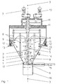
- An internal agitator 2 in is in a funnel-shaped mixing container the central axis 3 of the mixing container 1 attached that from a shaft 4 and a cylindrical or attached thereto conical screw 5 or helically arranged wings consists.
- This agitator 2 extends directly to the Lock slide 6 and is on the opposite Side driven by a drive 7.
- An external agitator with mixing arms 8 and attached blades 9, which the coat the surface of the mixing container 1 touched by the mix, is mounted coaxially to agitator 2 and by the drive 10 driven. Both drives 7 and 10 can also are infinitely variable.
- the Drives 7 and 10 and the mixing container 1 are on one Support structure 11 attached, which in turn rigid or over rubber-elastic pads 12 is connected to the system 13, if a vibrator 14 is used on the mixing container 1 should.
- the mixing container is at its outlet end with the help of a Seal 17 and the shutter operated by the actuator 15 6 sealed for transferring the mix a tube or hose 16 is used in the transport container.
- This embodiment has the advantage that the outer agitator the material in both directions pushes off the wall.
- the mixing arms 8 are designed that the coulters face the container wall surface Adjust the bottom to the direction of the wall.
- the mixing arms 8 and the shares 9 are in for this purpose vertical direction and at an angle to the container wall adjustable.
Description
- Fig. 1
- einen Schnitt durch einen Zwangsmischer;
- Fig. 2
- ein Detail aus Fig. 1 mit einer Schnittdetaildarstellung eines Abstreifers; und
- Fig. 3
- einen Gang der Schnecke des inneren Rührwerks in Draufsicht bzw. Seitenansicht.
Claims (8)
- Zwangsmischer zum Mischen von Komponenten mit einem trichterförmigen Mischraum, in dessen Mittelachse (3) koaxial ein inneres und ein äußeres Rührwerk angebracht sind, wobei das innere Rührwerk (2) aus einer Schnecke (5) besteht, die bis zum Auslaufschieber (6) reicht, wobei das äußere Rührwerk (8) Mischscharen (9) bzw. Abstreifer aufweist, dadurch gekennzeichnet, daß die Mischscharen (9) bzw. Abstreifer die vom Mischgut berührten Mischbehälterflächen (1) bestreichen und das äußere Rührwerk (8)einen Antrieb (10) aufweist, durch den das äußere Rührwerk (8) intervallartig zwischen einer ersten Drehrichtung und einer entgegengesetzten Drehrichtung wechselnd antreibbar ist.
- Zwangsmischer nach Anspruch 1, dadurch gekennzeichnet, daß die Schnecke (5) des inneren Rührwerks (2) zylindrisch ausgebildet ist.
- Zwangsmischer nach Anspruch 1, dadurch gekennzeichnet, daß die Schnecke (5) des inneren Rührwerks (2) konisch, d.h. mit nach oben zunehmendem Durchmesser ausgebildet ist.
- Zwangsmischer nach einem der Ansprüche 1 bis 3, dadurch gekennzeichnet, daß das innere Rührwerk aus einer Welle mit schneckenförmig angeordneten Flügeln ausgebildet ist.
- Zwangsmischer nach einem der Ansprüche 1 bis 4, dadurch gekennzeichnet, daß an der Schnecke bzw. den übereinander angeordneten Flügeln (5) Schneidelemente (17) angeordnet sind.
- Zwangsmischer nach einem der Ansprüche 1 bis 5, dadurch gekennzeichnet, daß die Antriebe der beiden Rührwerke mit festen Drehzahlen ausgelegt sind.
- Zwangsmischer nach einem der Ansprüche 1 bis 5, dadurch gekennzeichnet, daß die Antriebe der beiden Rührwerke stufenlos regelbar sind.
- Zwangsmischer nach einem der Ansprüche 1 bis 7, dadurch gekennzeichnet, daß die Antriebe für die Rührwerke über gummi-elastische Auflagen gelagert sind und ein Rüttler 14 am Mischbehälter vorgesehen ist.
Applications Claiming Priority (3)
| Application Number | Priority Date | Filing Date | Title |
|---|---|---|---|
| DE19950743A DE19950743A1 (de) | 1999-10-21 | 1999-10-21 | KKM-Mischer |
| DE19950743 | 1999-10-21 | ||
| PCT/EP2000/009562 WO2001028672A1 (de) | 1999-10-21 | 2000-09-29 | Zwangsmischer, insbesondere als betonmischer |
Publications (2)
| Publication Number | Publication Date |
|---|---|
| EP1121193A1 EP1121193A1 (de) | 2001-08-08 |
| EP1121193B1 true EP1121193B1 (de) | 2002-11-27 |
Family
ID=7926418
Family Applications (1)
| Application Number | Title | Priority Date | Filing Date |
|---|---|---|---|
| EP00969349A Expired - Lifetime EP1121193B1 (de) | 1999-10-21 | 2000-09-29 | Zwangsmischer, insbesondere als betonmischer |
Country Status (10)
| Country | Link |
|---|---|
| US (1) | US6390664B1 (de) |
| EP (1) | EP1121193B1 (de) |
| JP (1) | JP3637310B2 (de) |
| CN (1) | CN1148253C (de) |
| AT (1) | ATE228392T1 (de) |
| DE (2) | DE19950743A1 (de) |
| DK (1) | DK1121193T3 (de) |
| HU (1) | HU222902B1 (de) |
| PL (1) | PL348104A1 (de) |
| WO (1) | WO2001028672A1 (de) |
Cited By (4)
| Publication number | Priority date | Publication date | Assignee | Title |
|---|---|---|---|---|
| DE102007036523A1 (de) * | 2007-04-18 | 2008-10-23 | Pemat Mischtechnik Gmbh | Mischer |
| DE102008060588A1 (de) | 2007-12-07 | 2009-06-10 | Pemat Mischtechnik Gmbh | Mischer |
| DE102011006636A1 (de) | 2011-04-01 | 2012-10-04 | Harald Kniele | Zwangsmischer mit Selbstreinigungsfunktion und Verwendung eines Innenrüttlers hierfür |
| EP2722103A2 (de) | 2012-10-19 | 2014-04-23 | Harald Kniele | Zwangsmischer mit Selbstreinigungsfunktion und Verwendung von Lufteinlässen hierfür |
Families Citing this family (34)
| Publication number | Priority date | Publication date | Assignee | Title |
|---|---|---|---|---|
| JP4841757B2 (ja) * | 2001-06-21 | 2011-12-21 | 五洋建設株式会社 | 建設汚泥、汚土、焼却灰等からなる粒状物の製造方法 |
| BR8203013Y1 (pt) * | 2002-10-25 | 2011-08-23 | disposição em tanque agitador usado em produtos cosméticos. | |
| WO2007129340A1 (en) * | 2006-05-10 | 2007-11-15 | Comber S.R.L. | Conical-base drier |
| JP4848292B2 (ja) * | 2007-01-18 | 2011-12-28 | 新日本製鐵株式会社 | 耐火物用混練機および耐火物の混練方法 |
| ATE493198T1 (de) | 2008-05-16 | 2011-01-15 | Inst Fertigteiltechnik Und Fertigbau Weimar E V | Mischwerkzeug und mischvorrichtung |
| CN101862617B (zh) * | 2009-04-14 | 2013-02-13 | 上海升立机械制造有限公司 | 立式胶浆混合机 |
| CN101898387A (zh) * | 2009-05-25 | 2010-12-01 | 福建南方路面机械有限公司 | 沥青水泥砂浆搅拌主机 |
| JP5418126B2 (ja) * | 2009-10-09 | 2014-02-19 | 新日鐵住金株式会社 | 不定形耐火物の混練方法 |
| FR2957832B1 (fr) * | 2010-03-23 | 2012-07-27 | Hmrexpert | Reservoir mobile de distribution de particules de glace |
| DE102010016596B4 (de) * | 2010-04-22 | 2015-10-22 | Zeppelin Reimelt Gmbh | Mischer |
| CN102294727A (zh) * | 2011-07-13 | 2011-12-28 | 王远洋 | 秸秆原料胶合机 |
| CN103100331A (zh) * | 2012-11-14 | 2013-05-15 | 江苏国立化工科技有限公司 | 多浆片锥形混合机 |
| FR3000906B1 (fr) * | 2013-01-15 | 2015-03-06 | Skako Concrete | Melangeur a cuve conique tournante |
| CN203579880U (zh) * | 2013-10-22 | 2014-05-07 | 四川宏劲机械有限公司 | 一种立轴搅拌机 |
| CN103692552B (zh) * | 2013-12-13 | 2015-09-23 | 四川宏劲机械有限公司 | 一种立式搅拌机 |
| CN103817798A (zh) * | 2014-03-20 | 2014-05-28 | 河南科技大学 | 一种混凝土搅拌装置 |
| CN104147963B (zh) * | 2014-08-22 | 2016-06-15 | 攀枝花市仁通钒业有限公司 | 混料搅拌机 |
| US9702567B2 (en) | 2014-11-14 | 2017-07-11 | William D. Owen | Heater system |
| CN104614198B (zh) * | 2015-01-16 | 2017-04-12 | 长安大学 | 一种工程集料四分法自动取样器及其取样方法 |
| JP6386958B2 (ja) * | 2015-03-27 | 2018-09-05 | 株式会社神鋼環境ソリューション | 撹拌装置 |
| JP6725504B2 (ja) * | 2015-07-01 | 2020-07-22 | 住友重機械プロセス機器株式会社 | 撹拌装置 |
| CN107724682B (zh) * | 2017-10-12 | 2019-12-17 | 合肥学院 | 一种土木工程用混凝土漏斗 |
| CN107722409A (zh) * | 2017-10-12 | 2018-02-23 | 合肥学院 | 土木工程用混凝土漏斗刮板的制作方法 |
| CN107722408A (zh) * | 2017-10-12 | 2018-02-23 | 合肥学院 | 土木工程混凝土漏斗用刮板 |
| CN107571400A (zh) * | 2017-10-23 | 2018-01-12 | 惠州市齐力建筑工程有限公司 | 一种具有打碎功能的混泥土搅拌机 |
| CN107972179A (zh) * | 2017-12-15 | 2018-05-01 | 上海建工建集团有限公司 | 混合料搅拌输送装置及施工方法 |
| CN108162176A (zh) * | 2017-12-19 | 2018-06-15 | 温州职业技术学院 | 一种混凝土搅拌机 |
| CN108568900B (zh) * | 2018-04-28 | 2019-09-10 | 重庆市长寿区分素装饰工程有限责任公司 | 建筑材料搅拌设备 |
| CN109483757B (zh) * | 2018-11-19 | 2021-06-01 | 绍兴柯桥新兴门业有限公司 | 一种高卸料功能的塑料外壳生产用立式搅拌机 |
| CN109571762A (zh) * | 2019-02-11 | 2019-04-05 | 刘德太 | 一种建筑施工用混凝土搅拌装置 |
| EP4106973A4 (de) * | 2020-02-17 | 2024-04-10 | Halkey Roberts Corp | Trichter für eine spritzgussmaschine |
| DE102021210248A1 (de) | 2021-09-16 | 2023-03-16 | Kniele Gmbh | Verschluss für Mischer |
| CN114307716B (zh) * | 2022-01-11 | 2022-10-04 | 深圳同道环保科技有限公司 | 一种用于污水处理药剂的搅拌装置 |
| CN116002239B (zh) * | 2023-03-28 | 2023-06-06 | 山东佳好食品科技有限公司 | 一种饮料储罐 |
Family Cites Families (56)
| Publication number | Priority date | Publication date | Assignee | Title |
|---|---|---|---|---|
| GB214446A (en) * | 1923-04-10 | 1924-04-24 | William Walter Veitch | Improvements in or relating to mixing apparatus |
| US1585169A (en) * | 1923-10-26 | 1926-05-18 | Perkins Glue Co | Mixing kettle |
| US2209287A (en) * | 1938-04-07 | 1940-07-23 | Wilbur L Simpson | Apparatus for mixing |
| NL142820C (de) * | 1940-08-27 | |||
| US2531305A (en) * | 1940-09-23 | 1950-11-21 | Smith Arthur Ronald | Hopper vertically adjustable for sealing contact with cover |
| US2589583A (en) * | 1947-05-23 | 1952-03-18 | Forrest G Thompson | Container filling machine having feed screw with cylindrical bore forming member |
| US2822934A (en) * | 1954-05-28 | 1958-02-11 | Donald E Bartelt | Dispensing device |
| US2851257A (en) * | 1954-06-15 | 1958-09-09 | Patterson Kelley Co | Mixing machine |
| BE567207A (fr) * | 1957-05-16 | 1958-10-28 | Melangeur conique | |
| DE1112443B (de) * | 1959-07-06 | 1961-08-03 | Niepmann & Co Maschf Fr | Vorrichtung zum Foerdern von plastischen Massen, insbesondere von Sprengstoff, bei Verpackungsmaschinen |
| US3191642A (en) * | 1962-09-24 | 1965-06-29 | Nissan Chemical Ind Ltd | Automatic feeder of pulverulent body |
| US3148802A (en) * | 1963-09-17 | 1964-09-15 | Autopack Ltd | Variable speed filling machine with successively actuated clutches |
| GB1021726A (en) * | 1963-10-23 | 1966-03-09 | Southall & Smith Ltd | Improvements relating to variable position control systems |
| US3248019A (en) * | 1964-05-18 | 1966-04-26 | Gen Mills Inc | Dispensing hopper having auger and agitator means |
| US3251512A (en) * | 1965-02-12 | 1966-05-17 | Baker Perkins Inc | Feeder means |
| DE1244723B (de) * | 1965-05-12 | 1967-07-20 | Karl Schlecht Dipl Ing | Vorrichtung zum kontinuierlichen Mischen von trockenem Gut mit einer Fluessigkeit |
| US3339896A (en) * | 1966-06-03 | 1967-09-05 | Southwestern Eng Co | Stirring device |
| DE1298401B (de) * | 1967-02-04 | 1969-06-26 | Loedige Fritz | Zwangsmischer mit lotrecht angeordnetem Mischbehaelter |
| US3616968A (en) * | 1969-04-10 | 1971-11-02 | Hayssen Mfg Co | Auger filler and control therefor |
| DE1927067A1 (de) * | 1969-05-28 | 1970-12-10 | Barmag Barmer Maschf | Schneckenpresse fuer thermoplastische Werkstoffe |
| US3602394A (en) * | 1969-06-27 | 1971-08-31 | Thomas F Mccune | Dispenser for silage additive |
| FR2114260A5 (de) * | 1970-11-20 | 1972-06-30 | Marchadour Jean Charles | |
| GB1373760A (en) * | 1970-12-21 | 1974-11-13 | Agricultural Cent Trading | Agricultural or horticultural broadcasting devices |
| US3746315A (en) * | 1970-12-28 | 1973-07-17 | Usm Corp | Mixing and transporting device and method of mixing and transporting |
| DE2457001A1 (de) * | 1974-12-03 | 1976-06-10 | Hedrich Vakuumanlagen Wilhelm | Vorrichtung zum extrem schnellen, kontinuierlich homogenen mischen, intensivem entgasen oder eindicken von aus mehreren komponenten bestehenden, mit oder ohne fuellstoffe legierten kunstharzen oder anderen kunststoffen |
| FR2353330A1 (fr) * | 1976-04-22 | 1977-12-30 | Demoulin Gerard | Appareil melangeur |
| CH595241A5 (de) * | 1976-10-05 | 1978-02-15 | Sig Schweiz Industrieges | |
| DE2818863C3 (de) * | 1978-04-26 | 1981-04-30 | Schering Ag Berlin Und Bergkamen, 1000 Berlin | Trocknungsvorrichtung |
| DE3026492A1 (de) * | 1980-07-12 | 1982-02-04 | Wilhelm Hedrich Vakuumanlagen GmbH und Co KG, 6332 Ehringshausen | Vorrichtung zum mischen und entgasen von komponenten von kunstharzen, insbesondere von duroplastischen kunstharzen |
| DE3027567A1 (de) * | 1980-07-21 | 1982-02-25 | Dieter 6570 Kirn Kupka | Ruehrwerk mit zwei um dieselbe geometrische achse gegenlaeufig angetriebenen ruehrorganen |
| DE3110437C2 (de) * | 1981-03-18 | 1985-08-01 | Werner & Pfleiderer, 7000 Stuttgart | Mischer |
| DE3230763A1 (de) * | 1982-08-16 | 1984-02-16 | Schering AG, 1000 Berlin und 4709 Bergkamen | Vorrichtung zum entfernen von substanzen an behaelterinnenwaenden |
| DE3332069A1 (de) * | 1983-09-06 | 1985-03-21 | Hoechst Ag | Ruehrer fuer wandnahes ruehren |
| US4633923A (en) * | 1985-05-02 | 1987-01-06 | Hauni-Werke Korber & Co. Kg. | Apparatus for filling ink cartridges |
| DE3524537A1 (de) * | 1985-07-10 | 1987-01-22 | Badische Maschf Gmbh | Vorrichtung zum mischen von feststoffen und fluessigkeiten |
| DE3602493A1 (de) * | 1986-01-28 | 1987-07-30 | Edelmann Carl Verpackung | Verfahren und vorrichtung zum dosierten, gewichtsgerechten abfuellen einer vorbestimmten menge eines fliessfaehigen abfuellguts |
| SE458665B (sv) * | 1986-10-20 | 1989-04-24 | Flaekt Ab | Foerfarande och anordning foer att blanda torrt pulverformigt material med en vaetska foer att bilda en slurry |
| JPH0265743U (de) * | 1988-11-04 | 1990-05-17 | ||
| US4944334A (en) * | 1988-11-14 | 1990-07-31 | Mcgregor Harold R | Vibrating hopper and auger feed assembly |
| US5327947A (en) * | 1988-11-14 | 1994-07-12 | Mcgregor Harold R | Vertical auger type bag filler having a vibrating bowl with inverted venting cone and rotating agitator assembly |
| US5109894A (en) * | 1988-11-14 | 1992-05-05 | Mcgregor Harold R | Vertical bottom-fill auger assembly |
| DE3905535C1 (de) * | 1989-02-23 | 1990-03-15 | Signode System Gmbh, 4220 Dinslaken, De | |
| CA2009905C (en) * | 1990-02-13 | 1994-08-30 | Michael Langford Malkoski | High density grout pump |
| US5102229A (en) * | 1990-06-15 | 1992-04-07 | Sumitomo Heavy Industries, Ltd | Agitator |
| US5339998A (en) * | 1993-10-26 | 1994-08-23 | Xerox Corporation | Auger feeding agitator |
| EP0659471B1 (de) * | 1993-12-27 | 1999-11-03 | Kajima Corporation | Mischvorrichtung und Verfahren |
| AUPM657894A0 (en) * | 1994-06-30 | 1994-07-21 | Hood, Max George | Method and apparatus for cement blending |
| US5527108A (en) * | 1995-01-25 | 1996-06-18 | A-1 Concrete Leveling, Inc. | Apparatus for charging a pumping device |
| US5718510A (en) * | 1995-02-28 | 1998-02-17 | Inco Limited | Paste production and storage apparatus |
| JPH09254135A (ja) * | 1996-03-19 | 1997-09-30 | Taiheiyo Kiko Kk | 混練物製造用ミキサ |
| US5647665A (en) * | 1996-04-18 | 1997-07-15 | Schuler Manufacturing & Equipment Co., Inc. | Vertical feed mixer with flighting plows |
| US5909829A (en) * | 1997-04-01 | 1999-06-08 | Xerox Corporation | Vibratory filler for powders |
| US5947169A (en) * | 1997-04-01 | 1999-09-07 | Xerox Corporation | Oscillating valve for powders |
| US6196278B1 (en) * | 1997-04-01 | 2001-03-06 | Xerox Corporation | Powder filling utilizing vibrofluidization |
| US6000446A (en) * | 1998-03-16 | 1999-12-14 | Xerox Corporation | Apparatus for particulate processing |
| DE19828559C1 (de) * | 1998-06-26 | 2000-03-16 | Chronos Richardson Gmbh | Dosiervorrichtung |
-
1999
- 1999-10-21 DE DE19950743A patent/DE19950743A1/de not_active Withdrawn
-
2000
- 2000-09-29 HU HU0104885A patent/HU222902B1/hu not_active IP Right Cessation
- 2000-09-29 AT AT00969349T patent/ATE228392T1/de active
- 2000-09-29 DK DK00969349T patent/DK1121193T3/da active
- 2000-09-29 CN CNB008023417A patent/CN1148253C/zh not_active Expired - Fee Related
- 2000-09-29 JP JP2001531496A patent/JP3637310B2/ja not_active Expired - Fee Related
- 2000-09-29 WO PCT/EP2000/009562 patent/WO2001028672A1/de active IP Right Grant
- 2000-09-29 DE DE50000815.9T patent/DE50000815C5/de not_active Expired - Lifetime
- 2000-09-29 PL PL00348104A patent/PL348104A1/xx not_active Application Discontinuation
- 2000-09-29 EP EP00969349A patent/EP1121193B1/de not_active Expired - Lifetime
- 2000-09-29 US US09/869,083 patent/US6390664B1/en not_active Expired - Fee Related
Cited By (4)
| Publication number | Priority date | Publication date | Assignee | Title |
|---|---|---|---|---|
| DE102007036523A1 (de) * | 2007-04-18 | 2008-10-23 | Pemat Mischtechnik Gmbh | Mischer |
| DE102008060588A1 (de) | 2007-12-07 | 2009-06-10 | Pemat Mischtechnik Gmbh | Mischer |
| DE102011006636A1 (de) | 2011-04-01 | 2012-10-04 | Harald Kniele | Zwangsmischer mit Selbstreinigungsfunktion und Verwendung eines Innenrüttlers hierfür |
| EP2722103A2 (de) | 2012-10-19 | 2014-04-23 | Harald Kniele | Zwangsmischer mit Selbstreinigungsfunktion und Verwendung von Lufteinlässen hierfür |
Also Published As
| Publication number | Publication date |
|---|---|
| EP1121193A1 (de) | 2001-08-08 |
| CN1148253C (zh) | 2004-05-05 |
| DE19950743A1 (de) | 2001-04-26 |
| CN1327397A (zh) | 2001-12-19 |
| JP2003512151A (ja) | 2003-04-02 |
| HUP0104885A2 (hu) | 2002-04-29 |
| DE50000815C5 (de) | 2015-05-21 |
| JP3637310B2 (ja) | 2005-04-13 |
| PL348104A1 (en) | 2002-05-06 |
| HU222902B1 (hu) | 2003-12-29 |
| WO2001028672A1 (de) | 2001-04-26 |
| US6390664B1 (en) | 2002-05-21 |
| HUP0104885A3 (en) | 2003-02-28 |
| DE50000815D1 (de) | 2003-01-09 |
| DK1121193T3 (da) | 2003-03-10 |
| ATE228392T1 (de) | 2002-12-15 |
Similar Documents
| Publication | Publication Date | Title |
|---|---|---|
| EP1121193B1 (de) | Zwangsmischer, insbesondere als betonmischer | |
| EP3702023B1 (de) | Schräglagenmischer | |
| EP2226117A2 (de) | Verfahren zum Mischen von pulver- und/oder granulatförmigen Stoffen sowie Mischmaschine | |
| DE10113462A1 (de) | Dosiervorrichtung für Schüttgüter | |
| EP1713572A1 (de) | Vorrichtung zum dosieren von schü ttgütern | |
| DE2047650A1 (de) | Verfahren zur Herstellung eines im wesentlichen klumpenfreien Gemisches | |
| DE10110910C1 (de) | Mischer zum Herstellen pastöser Produkte wie Salben, Cremes und Emulsionen | |
| DE1557115B2 (de) | Vorrichtung zum mischen von fluessigkeiten | |
| DE1629717A1 (de) | Mischmaschinenantrieb | |
| CH689776A5 (de) | Misch- und Foerdergeraet fuer ein plastisches Material, insbesondere einen Verputz. | |
| DE1054811B (de) | Mechanischer Umlaufmischer mit einem laenglichen, geschlossenen Mischtrog | |
| DE1941831A1 (de) | Mischmaschine | |
| EP0211230A2 (de) | Vorrichtung zum Mischen von Feststoffen und Flüssigkeiten | |
| WO2000002799A1 (de) | Vorrichtung zum erreichen eines kontinuierlichen materialflusses bei schüttgütern | |
| EP1236690B1 (de) | Vorrichtung zum Mischen und Trocknen von Schlickstoffen | |
| EP2119496B1 (de) | Mischwerkzeug und Mischvorrichtung | |
| DE2336699C2 (de) | Vorrichtung zum Mischen von Baustoffen | |
| DE2440461A1 (de) | Mischwerk fuer betonmischmaschinen | |
| DE2446607C3 (de) | Ringtrogmischer | |
| WO1992009361A1 (de) | Vorrichtung für das mischen, homogenisieren oder umsetzen von wenigstens zwei komponenten | |
| EP3792207B1 (de) | Dosiervorrichtung | |
| DE3544497C2 (de) | ||
| EP3189889A1 (de) | Mischvorrichtung und mischwerkzeug | |
| DE2314344B1 (de) | Mischer fuer die kontinuierliche Aufbereitung von fliessfaehigem Mischgut | |
| DE2336104C3 (de) | Kegelschneckenmischer |
Legal Events
| Date | Code | Title | Description |
|---|---|---|---|
| PUAI | Public reference made under article 153(3) epc to a published international application that has entered the european phase |
Free format text: ORIGINAL CODE: 0009012 |
|
| 17P | Request for examination filed |
Effective date: 20010427 |
|
| AK | Designated contracting states |
Kind code of ref document: A1 Designated state(s): AT BE CH CY DE DK ES FI FR GB GR IE IT LI LU MC NL PT SE |
|
| AX | Request for extension of the european patent |
Free format text: AL;LT;LV;MK;RO;SI |
|
| 17Q | First examination report despatched |
Effective date: 20010813 |
|
| GRAG | Despatch of communication of intention to grant |
Free format text: ORIGINAL CODE: EPIDOS AGRA |
|
| GRAG | Despatch of communication of intention to grant |
Free format text: ORIGINAL CODE: EPIDOS AGRA |
|
| GRAG | Despatch of communication of intention to grant |
Free format text: ORIGINAL CODE: EPIDOS AGRA |
|
| GRAH | Despatch of communication of intention to grant a patent |
Free format text: ORIGINAL CODE: EPIDOS IGRA |
|
| GRAH | Despatch of communication of intention to grant a patent |
Free format text: ORIGINAL CODE: EPIDOS IGRA |
|
| GRAA | (expected) grant |
Free format text: ORIGINAL CODE: 0009210 |
|
| AK | Designated contracting states |
Kind code of ref document: B1 Designated state(s): AT BE CH CY DE DK ES FI FR GB GR IE IT LI LU MC NL PT SE |
|
| AX | Request for extension of the european patent |
Free format text: AL;LT;LV;MK;RO;SI |
|
| PG25 | Lapsed in a contracting state [announced via postgrant information from national office to epo] |
Ref country code: IE Free format text: LAPSE BECAUSE OF FAILURE TO SUBMIT A TRANSLATION OF THE DESCRIPTION OR TO PAY THE FEE WITHIN THE PRESCRIBED TIME-LIMIT Effective date: 20021127 Ref country code: GR Free format text: LAPSE BECAUSE OF FAILURE TO SUBMIT A TRANSLATION OF THE DESCRIPTION OR TO PAY THE FEE WITHIN THE PRESCRIBED TIME-LIMIT Effective date: 20021127 Ref country code: FI Free format text: LAPSE BECAUSE OF FAILURE TO SUBMIT A TRANSLATION OF THE DESCRIPTION OR TO PAY THE FEE WITHIN THE PRESCRIBED TIME-LIMIT Effective date: 20021127 |
|
| REF | Corresponds to: |
Ref document number: 228392 Country of ref document: AT Date of ref document: 20021215 Kind code of ref document: T |
|
| REG | Reference to a national code |
Ref country code: GB Ref legal event code: FG4D Free format text: NOT ENGLISH |
|
| REG | Reference to a national code |
Ref country code: CH Ref legal event code: EP |
|
| REG | Reference to a national code |
Ref country code: CH Ref legal event code: NV Representative=s name: R. A. EGLI & CO. PATENTANWAELTE |
|
| REG | Reference to a national code |
Ref country code: IE Ref legal event code: FG4D Free format text: GERMAN |
|
| REF | Corresponds to: |
Ref document number: 50000815 Country of ref document: DE Date of ref document: 20030109 |
|
| GBT | Gb: translation of ep patent filed (gb section 77(6)(a)/1977) |
Effective date: 20030113 |
|
| PG25 | Lapsed in a contracting state [announced via postgrant information from national office to epo] |
Ref country code: PT Free format text: LAPSE BECAUSE OF FAILURE TO SUBMIT A TRANSLATION OF THE DESCRIPTION OR TO PAY THE FEE WITHIN THE PRESCRIBED TIME-LIMIT Effective date: 20030227 Ref country code: SE Free format text: LAPSE BECAUSE OF FAILURE TO SUBMIT A TRANSLATION OF THE DESCRIPTION OR TO PAY THE FEE WITHIN THE PRESCRIBED TIME-LIMIT Effective date: 20030227 |
|
| REG | Reference to a national code |
Ref country code: DK Ref legal event code: T3 |
|
| ET | Fr: translation filed | ||
| LTIE | Lt: invalidation of european patent or patent extension |
Effective date: 20021127 |
|
| PG25 | Lapsed in a contracting state [announced via postgrant information from national office to epo] |
Ref country code: ES Free format text: LAPSE BECAUSE OF FAILURE TO SUBMIT A TRANSLATION OF THE DESCRIPTION OR TO PAY THE FEE WITHIN THE PRESCRIBED TIME-LIMIT Effective date: 20030529 |
|
| REG | Reference to a national code |
Ref country code: IE Ref legal event code: FD4D Ref document number: 1121193E Country of ref document: IE |
|
| PG25 | Lapsed in a contracting state [announced via postgrant information from national office to epo] |
Ref country code: LU Free format text: LAPSE BECAUSE OF NON-PAYMENT OF DUE FEES Effective date: 20030929 Ref country code: CY Free format text: LAPSE BECAUSE OF FAILURE TO SUBMIT A TRANSLATION OF THE DESCRIPTION OR TO PAY THE FEE WITHIN THE PRESCRIBED TIME-LIMIT Effective date: 20030929 |
|
| PG25 | Lapsed in a contracting state [announced via postgrant information from national office to epo] |
Ref country code: MC Free format text: LAPSE BECAUSE OF NON-PAYMENT OF DUE FEES Effective date: 20030930 |
|
| PLBE | No opposition filed within time limit |
Free format text: ORIGINAL CODE: 0009261 |
|
| STAA | Information on the status of an ep patent application or granted ep patent |
Free format text: STATUS: NO OPPOSITION FILED WITHIN TIME LIMIT |
|
| 26N | No opposition filed |
Effective date: 20030828 |
|
| PGFP | Annual fee paid to national office [announced via postgrant information from national office to epo] |
Ref country code: GB Payment date: 20040915 Year of fee payment: 5 |
|
| PGFP | Annual fee paid to national office [announced via postgrant information from national office to epo] |
Ref country code: FR Payment date: 20040917 Year of fee payment: 5 Ref country code: NL Payment date: 20040917 Year of fee payment: 5 |
|
| PGFP | Annual fee paid to national office [announced via postgrant information from national office to epo] |
Ref country code: BE Payment date: 20040923 Year of fee payment: 5 |
|
| PGFP | Annual fee paid to national office [announced via postgrant information from national office to epo] |
Ref country code: DK Payment date: 20050926 Year of fee payment: 6 |
|
| PG25 | Lapsed in a contracting state [announced via postgrant information from national office to epo] |
Ref country code: GB Free format text: LAPSE BECAUSE OF NON-PAYMENT OF DUE FEES Effective date: 20050929 |
|
| PG25 | Lapsed in a contracting state [announced via postgrant information from national office to epo] |
Ref country code: BE Free format text: LAPSE BECAUSE OF NON-PAYMENT OF DUE FEES Effective date: 20050930 |
|
| PG25 | Lapsed in a contracting state [announced via postgrant information from national office to epo] |
Ref country code: NL Free format text: LAPSE BECAUSE OF NON-PAYMENT OF DUE FEES Effective date: 20060401 |
|
| GBPC | Gb: european patent ceased through non-payment of renewal fee |
Effective date: 20050929 |
|
| PG25 | Lapsed in a contracting state [announced via postgrant information from national office to epo] |
Ref country code: FR Free format text: LAPSE BECAUSE OF NON-PAYMENT OF DUE FEES Effective date: 20060531 |
|
| NLV4 | Nl: lapsed or anulled due to non-payment of the annual fee |
Effective date: 20060401 |
|
| REG | Reference to a national code |
Ref country code: FR Ref legal event code: ST Effective date: 20060531 |
|
| PG25 | Lapsed in a contracting state [announced via postgrant information from national office to epo] |
Ref country code: DK Free format text: LAPSE BECAUSE OF NON-PAYMENT OF DUE FEES Effective date: 20061002 |
|
| REG | Reference to a national code |
Ref country code: DK Ref legal event code: EBP |
|
| BERE | Be: lapsed |
Owner name: *KNIELE HARALD Effective date: 20050930 Owner name: *KNIELE ALEXANDER Effective date: 20050930 |
|
| REG | Reference to a national code |
Ref country code: DE Ref legal event code: R008 Ref document number: 50000815 Country of ref document: DE |
|
| REG | Reference to a national code |
Ref country code: DE Ref legal event code: R039 Ref document number: 50000815 Country of ref document: DE Effective date: 20110211 |
|
| REG | Reference to a national code |
Ref country code: DE Ref legal event code: R043 Ref document number: 50000815 Country of ref document: DE |
|
| REG | Reference to a national code |
Ref country code: DE Ref legal event code: R043 Ref document number: 50000815 Country of ref document: DE Effective date: 20141202 |
|
| REG | Reference to a national code |
Ref country code: DE Ref legal event code: R206 Ref document number: 50000815 Country of ref document: DE Effective date: 20150521 |
|
| PGFP | Annual fee paid to national office [announced via postgrant information from national office to epo] |
Ref country code: CH Payment date: 20170925 Year of fee payment: 18 Ref country code: IT Payment date: 20170926 Year of fee payment: 18 |
|
| PGFP | Annual fee paid to national office [announced via postgrant information from national office to epo] |
Ref country code: AT Payment date: 20170925 Year of fee payment: 18 |
|
| REG | Reference to a national code |
Ref country code: CH Ref legal event code: PL |
|
| REG | Reference to a national code |
Ref country code: AT Ref legal event code: MM01 Ref document number: 228392 Country of ref document: AT Kind code of ref document: T Effective date: 20180929 |
|
| PG25 | Lapsed in a contracting state [announced via postgrant information from national office to epo] |
Ref country code: IT Free format text: LAPSE BECAUSE OF NON-PAYMENT OF DUE FEES Effective date: 20180929 |
|
| PG25 | Lapsed in a contracting state [announced via postgrant information from national office to epo] |
Ref country code: LI Free format text: LAPSE BECAUSE OF NON-PAYMENT OF DUE FEES Effective date: 20180930 Ref country code: CH Free format text: LAPSE BECAUSE OF NON-PAYMENT OF DUE FEES Effective date: 20180930 |
|
| PG25 | Lapsed in a contracting state [announced via postgrant information from national office to epo] |
Ref country code: AT Free format text: LAPSE BECAUSE OF NON-PAYMENT OF DUE FEES Effective date: 20180929 |
|
| PGFP | Annual fee paid to national office [announced via postgrant information from national office to epo] |
Ref country code: DE Payment date: 20190926 Year of fee payment: 20 |
|
| REG | Reference to a national code |
Ref country code: DE Ref legal event code: R071 Ref document number: 50000815 Country of ref document: DE |