EP1122564A2 - Ferrule for an optical fiber and manufacturing method thereof - Google Patents
Ferrule for an optical fiber and manufacturing method thereof Download PDFInfo
- Publication number
- EP1122564A2 EP1122564A2 EP01101893A EP01101893A EP1122564A2 EP 1122564 A2 EP1122564 A2 EP 1122564A2 EP 01101893 A EP01101893 A EP 01101893A EP 01101893 A EP01101893 A EP 01101893A EP 1122564 A2 EP1122564 A2 EP 1122564A2
- Authority
- EP
- European Patent Office
- Prior art keywords
- capillary
- flange
- ferrule
- optical fiber
- molded
- Prior art date
- Legal status (The legal status is an assumption and is not a legal conclusion. Google has not performed a legal analysis and makes no representation as to the accuracy of the status listed.)
- Withdrawn
Links
Images


Classifications
-
- G—PHYSICS
- G02—OPTICS
- G02B—OPTICAL ELEMENTS, SYSTEMS OR APPARATUS
- G02B6/00—Light guides; Structural details of arrangements comprising light guides and other optical elements, e.g. couplings
- G02B6/24—Coupling light guides
- G02B6/36—Mechanical coupling means
- G02B6/38—Mechanical coupling means having fibre to fibre mating means
- G02B6/3807—Dismountable connectors, i.e. comprising plugs
- G02B6/3833—Details of mounting fibres in ferrules; Assembly methods; Manufacture
- G02B6/3846—Details of mounting fibres in ferrules; Assembly methods; Manufacture with fibre stubs
-
- G—PHYSICS
- G02—OPTICS
- G02B—OPTICAL ELEMENTS, SYSTEMS OR APPARATUS
- G02B6/00—Light guides; Structural details of arrangements comprising light guides and other optical elements, e.g. couplings
- G02B6/24—Coupling light guides
- G02B6/26—Optical coupling means
- G02B6/264—Optical coupling means with optical elements between opposed fibre ends which perform a function other than beam splitting
- G02B6/266—Optical coupling means with optical elements between opposed fibre ends which perform a function other than beam splitting the optical element being an attenuator
-
- G—PHYSICS
- G02—OPTICS
- G02B—OPTICAL ELEMENTS, SYSTEMS OR APPARATUS
- G02B6/00—Light guides; Structural details of arrangements comprising light guides and other optical elements, e.g. couplings
- G02B6/24—Coupling light guides
- G02B6/36—Mechanical coupling means
- G02B6/38—Mechanical coupling means having fibre to fibre mating means
- G02B6/3807—Dismountable connectors, i.e. comprising plugs
- G02B6/3833—Details of mounting fibres in ferrules; Assembly methods; Manufacture
- G02B6/3865—Details of mounting fibres in ferrules; Assembly methods; Manufacture fabricated by using moulding techniques
-
- G—PHYSICS
- G02—OPTICS
- G02B—OPTICAL ELEMENTS, SYSTEMS OR APPARATUS
- G02B6/00—Light guides; Structural details of arrangements comprising light guides and other optical elements, e.g. couplings
- G02B6/24—Coupling light guides
- G02B6/36—Mechanical coupling means
- G02B6/38—Mechanical coupling means having fibre to fibre mating means
- G02B6/3807—Dismountable connectors, i.e. comprising plugs
- G02B6/3873—Connectors using guide surfaces for aligning ferrule ends, e.g. tubes, sleeves, V-grooves, rods, pins, balls
- G02B6/3874—Connectors using guide surfaces for aligning ferrule ends, e.g. tubes, sleeves, V-grooves, rods, pins, balls using tubes, sleeves to align ferrules
Abstract
Description
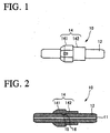
According to the present invention, there is provided a ferrule for a fiber optic connector having a capillary for receiving an optical fiber and a flange molded onto an outer surface of the capillary such that the capillary outer surface proximate each opposing end is not covered by the molded flange. With such an arrangement, as the flange is molded onto the outer surface of the capillary, there is no damage to the surface of the capillary during attachment of the flange. Accordingly, precise control of the outer diameter of the capillary is maintained. Furthermore, since the flange is molded directly onto the outer surface of the capillary, the position of the flange with respect to the capillary can be set with a high degree of accuracy and maintained.
Also according to the present invention, a recess portion may be formed in the outer surface of the capillary into which a corresponding projecting portion (formed during molding) of the flange will extend. Alternatively, the projecting portion may be formed in the outer surface of the capillary prior to molding of the flange, and the molding material may fill in a space surrounding the capillary projecting portion during the molding operation. However, it is easier to form the recess portion in the outer surface of the capillary and to form the projecting portion in the flange during molding. With either of these arrangements, it is possible to further ensure the positioning of the flange with respect to the capillary.
For purposes of positioning and securing the ferrule within a fiber optic connector, the flange described above may also incorporate a large diameter portion and a small diameter portion. These portions may be easily formed during the molding process.
Claims (9)
- A ferrule (10) for an optical fiber connector comprising:a capillary (12) having a pair of opposing ends, an outer surface extending between the opposing ends and a hole (11) extending between the opposing ends for insertion of an optical fiber strand therein;a flange (14) molded onto the capillary outer surface intermediate the capillary opposing ends such that the capillary outer surface proximate each opposing end is not covered by the molded flange (14).
- The ferrule (10) of claim 1, wherein the flange (14) is molded from a plastic material.
- The ferrule (10) of claim 1, further comprising a recess portion (15) and a complementary projecting portion (16) extending into the recess portion (15), the recess portion (15) and projecting portion (16) being formed at an interface between the capillary outer surface and the flange (14).
- The ferrule (10) of claim 3, wherein the recess portion (15) is formed in the capillary outer surface and the projecting portion (16) is formed integral with the flange (14).
- The ferrule (10) of claim 3, wherein the recess portion is formed integral with the flange (14) and the projecting portion is formed in the capillary outer surface.
- The ferrule (10) of claim 1, wherein the flange (14) has a cylindrical outer surface comprising a large diameter portion (141) and a small diameter portion (142).
- A method for manufacturing a ferrule (10) for an optical fiber connector comprising the step of molding a flange (14) onto an outer surface of a capillary (12) intermediate opposing ends of the capillary (12) such that the capillary outer surface proximate each opposing end is not covered by the molded flange (14).
- The method for manufacturing a ferrule (10) according to claim 7, further comprising the steps of:forming a recess portion (15) in the outer surface of the capillary (12) prior to molding; andforming, integral with the flange (14), a complementary projecting portion (16) that extends intimately into the recess portion (15) of the capillary outer surface during molding of the flange (14).
- The method for manufacturing a ferrule (10) according to claim 7, further comprising the steps of:forming a projecting portion in the outer surface of the capillary (12); andfilling a space surrounding the projecting portion with a molding material during molding.
Applications Claiming Priority (2)
| Application Number | Priority Date | Filing Date | Title |
|---|---|---|---|
| JP2000027305 | 2000-01-31 | ||
| JP2000027305A JP2001215358A (en) | 2000-01-31 | 2000-01-31 | Optical fiber ferrule and its manufacturing method |
Publications (2)
| Publication Number | Publication Date |
|---|---|
| EP1122564A2 true EP1122564A2 (en) | 2001-08-08 |
| EP1122564A3 EP1122564A3 (en) | 2004-06-16 |
Family
ID=18552893
Family Applications (1)
| Application Number | Title | Priority Date | Filing Date |
|---|---|---|---|
| EP01101893A Withdrawn EP1122564A3 (en) | 2000-01-31 | 2001-01-27 | Ferrule for an optical fiber and manufacturing method thereof |
Country Status (5)
| Country | Link |
|---|---|
| US (1) | US6726370B2 (en) |
| EP (1) | EP1122564A3 (en) |
| JP (1) | JP2001215358A (en) |
| CN (1) | CN1257418C (en) |
| TW (1) | TW571134B (en) |
Cited By (11)
| Publication number | Priority date | Publication date | Assignee | Title |
|---|---|---|---|---|
| US6726370B2 (en) * | 2000-01-31 | 2004-04-27 | Molex Incorporated | Ferrule for an optical fiber and manufacturing method thereof |
| EP1467239A3 (en) * | 2003-04-09 | 2005-01-26 | KiloLambda IP Limited | Optical power limiter |
| US7118289B2 (en) | 2002-02-25 | 2006-10-10 | Kyoueisenzai Kabushikigaisha | Optical fiber composite ferrule |
| EP2112535A1 (en) | 2008-04-02 | 2009-10-28 | Tyco Electronics Corporation | Optical attenuator |
| US8478087B2 (en) | 2002-01-10 | 2013-07-02 | Kilolambda Technologies Ltd. | Optical limiter |
| CN104011572A (en) * | 2011-11-23 | 2014-08-27 | Adc电信公司 | Multi-fiber fiber optic connector |
| US8939654B2 (en) | 2012-09-27 | 2015-01-27 | Adc Telecommunications, Inc. | Ruggedized multi-fiber fiber optic connector with sealed dust cap |
| US9016953B2 (en) | 2012-02-20 | 2015-04-28 | Adc Telecommunications, Inc. | Fiber optic connector, fiber optic connector and cable assembly, and methods for manufacturing |
| US9268102B2 (en) | 2012-02-07 | 2016-02-23 | Tyco Electronics Raychem Bvba | Cable termination assembly and method for connectors |
| US9720185B2 (en) | 2014-05-23 | 2017-08-01 | Commscope Technologies Llc | Systems and method for processing optical cable assemblies |
| WO2020076248A3 (en) * | 2018-04-02 | 2020-05-28 | Ates Erdal | Water-based liquid adhesive |
Families Citing this family (14)
| Publication number | Priority date | Publication date | Assignee | Title |
|---|---|---|---|---|
| JP4061161B2 (en) * | 2002-09-26 | 2008-03-12 | 京セラ株式会社 | Optical device manufacturing method |
| JP3979396B2 (en) * | 2003-03-07 | 2007-09-19 | 住友電気工業株式会社 | Optical module and manufacturing method thereof |
| JP2005148250A (en) * | 2003-11-13 | 2005-06-09 | Molex Inc | Optical fixed attenuator and its flange |
| US6902327B1 (en) * | 2003-12-10 | 2005-06-07 | Yazaki North America, Inc. | Apparatus and method for laser welding a ferrule to a fiber optic cable |
| DE202004020043U1 (en) * | 2004-12-22 | 2006-02-09 | CCS Technology, Inc., Wilmington | Fiber optic connection device, plug and connector for optical fibers |
| US20080089650A1 (en) * | 2006-05-24 | 2008-04-17 | Fiber Systems International D/B/A Amphenol Fiber Systems International | Fiber optic connector |
| US8419294B2 (en) * | 2008-04-28 | 2013-04-16 | Adamant Kogyo Co., Ltd. | Housing for optical connector and optical connector |
| JP2010054703A (en) * | 2008-08-27 | 2010-03-11 | Nippon Electric Glass Co Ltd | Capillary tube for fixing optical fiber |
| RU2510057C1 (en) * | 2012-09-10 | 2014-03-20 | Российская Федерация, От Имени Которой Выступает Министерство Промышленности И Торговли Российской Федерации | Method of making ceramic connector for connecting optical fibres |
| CN107608032B (en) | 2014-07-01 | 2019-12-20 | 泰科电子(上海)有限公司 | Optical fiber alignment device, ferrule device and method for manufacturing ferrule device |
| CN105445864B (en) * | 2014-07-01 | 2017-12-05 | 泰科电子(上海)有限公司 | Ferrule assembly and lock pin device |
| JP1536598S (en) * | 2014-12-10 | 2015-11-02 | ||
| CN107918174A (en) | 2016-10-11 | 2018-04-17 | 康普技术有限责任公司 | Ferrule assembly, the method and optical fiber fixing mould for manufacturing ferrule assembly |
| WO2018152175A1 (en) * | 2017-02-15 | 2018-08-23 | Molex, Llc | Multi-fiber optical assemblies and method of making same |
Citations (1)
| Publication number | Priority date | Publication date | Assignee | Title |
|---|---|---|---|---|
| GB2176629A (en) * | 1985-06-13 | 1986-12-31 | Sumitomo Electric Industries | Independant optical fibre ferrule |
Family Cites Families (34)
| Publication number | Priority date | Publication date | Assignee | Title |
|---|---|---|---|---|
| JPS5667812A (en) * | 1979-11-06 | 1981-06-08 | Nippon Telegr & Teleph Corp <Ntt> | Plug for optical fiber connector |
| GB2097021B (en) * | 1981-04-22 | 1984-02-22 | Nippon Telegraph & Telephone | Method for production of optical fiber connectors |
| JPS60198509A (en) * | 1984-03-22 | 1985-10-08 | Sumitomo Electric Ind Ltd | Optical connector ferrule and its production |
| US4818061A (en) * | 1984-09-05 | 1989-04-04 | Nippon Telegraph And Telephone Corporation | Ferrule for connecting optical fibers and optical connector using it |
| FR2598821B1 (en) * | 1986-05-15 | 1989-12-01 | Radiall Ind | CONNECTOR CAP FOR SINGLE-MODE OPTICAL FIBERS WITH POLARIZATION HOLD AND METHOD OF ADJUSTING THE SAME. |
| KR910000063B1 (en) * | 1986-06-13 | 1991-01-19 | 스미도모덴기고오교오 가부시기가이샤 | Optical cornector ferrule |
| US4815809A (en) * | 1987-07-31 | 1989-03-28 | Robert M. Rodrick | Method and apparatus for terminating an optical fiber |
| US4822130A (en) | 1987-08-21 | 1989-04-18 | Hughes Aircraft Company | Fiber optic hermetic feedthrough |
| US4911518A (en) | 1989-03-09 | 1990-03-27 | Amp Incorporated | Threaded front end connector for optical fiber and method of making same |
| JP3088779B2 (en) | 1991-05-24 | 2000-09-18 | 古河電気工業株式会社 | Mold for molding ferrule for optical connector |
| US5158900A (en) * | 1991-10-18 | 1992-10-27 | Hewlett-Packard Company | Method of separately fabricating a base/emitter structure of a BiCMOS device |
| US5216734A (en) | 1992-06-12 | 1993-06-01 | Amp Incorporated | Fiber optic connector having low cost ferrule |
| US5375183A (en) | 1993-05-25 | 1994-12-20 | The Whitaker Corporation | Overmolded alignment ferrule |
| JPH07168054A (en) * | 1993-12-13 | 1995-07-04 | Furukawa Electric Co Ltd:The | Optical connector ferrule |
| US5621835A (en) * | 1994-05-20 | 1997-04-15 | Seikoh Giken Co., Ltd. | Optical fiber assembly and manufacturing method for the same |
| EP0693698B1 (en) | 1994-07-21 | 2001-07-04 | Sumitomo Electric Industries, Ltd. | Optical waveguide module having waveguide substrate made of predetermined material and ferrule made of material different from that of waveguide substrate |
| US5588079A (en) * | 1995-02-17 | 1996-12-24 | Nec Corporation | Optical connector |
| JPH09171125A (en) * | 1995-12-19 | 1997-06-30 | Emitsuto Seiko Kk | Optical connector |
| US5719977A (en) | 1996-04-23 | 1998-02-17 | Lucent Technologies Inc. | Optical connector with immovable ferrule |
| JP3145639B2 (en) * | 1996-07-10 | 2001-03-12 | 三菱電線工業株式会社 | Optical connector for high energy |
| US5751875A (en) | 1996-10-04 | 1998-05-12 | The Whitaker Corporation | Optical fiber ferrule |
| JP3326087B2 (en) | 1996-12-26 | 2002-09-17 | 明久 井上 | Ferrule for optical fiber connector and method of manufacturing the same |
| EP0860723A3 (en) | 1997-02-21 | 1999-08-04 | Nippon Telegraph and Telephone Corporation | Plastic Ferrule for optical connector and method for production thereof |
| JPH10300983A (en) * | 1997-02-27 | 1998-11-13 | Seiko Instr Inc | Lock ring and optical fiber termination structure |
| JPH11160572A (en) * | 1997-11-28 | 1999-06-18 | Kyocera Corp | Ferrule for optical fiber connector |
| JP3934234B2 (en) * | 1998-01-21 | 2007-06-20 | 富士通株式会社 | Receptacle module |
| US6102581A (en) | 1998-06-16 | 2000-08-15 | Lucent Technologies Inc. | Optical adapter including a ferrule assembly |
| JP3311681B2 (en) * | 1998-07-07 | 2002-08-05 | 株式会社精工技研 | Variable optical attenuator with latching ratchet |
| JP3440408B2 (en) * | 1998-07-10 | 2003-08-25 | 日本モレックス株式会社 | Ferrule for optical connector |
| JP3516256B2 (en) * | 1998-07-31 | 2004-04-05 | 矢崎総業株式会社 | Optical fiber fixing structure of ferrule |
| JP2000147320A (en) * | 1998-11-16 | 2000-05-26 | Ykk Corp | Ferrule for optical connector as well as its production and apparatus therefor |
| JP2001051157A (en) * | 1999-08-11 | 2001-02-23 | Kyocera Corp | Optical fiber fixture, its manufacture, and optical fiber connector using it |
| JP2001100065A (en) * | 1999-10-01 | 2001-04-13 | Ykk Corp | Optical fiber integrated type ferrule and its manufacturing method |
| JP2001215358A (en) * | 2000-01-31 | 2001-08-10 | Molex Inc | Optical fiber ferrule and its manufacturing method |
-
2000
- 2000-01-31 JP JP2000027305A patent/JP2001215358A/en active Pending
-
2001
- 2001-01-26 US US09/771,273 patent/US6726370B2/en not_active Expired - Fee Related
- 2001-01-27 EP EP01101893A patent/EP1122564A3/en not_active Withdrawn
- 2001-01-30 CN CN01110842.8A patent/CN1257418C/en not_active Expired - Fee Related
- 2001-03-14 TW TW090101798A patent/TW571134B/en not_active IP Right Cessation
Patent Citations (1)
| Publication number | Priority date | Publication date | Assignee | Title |
|---|---|---|---|---|
| GB2176629A (en) * | 1985-06-13 | 1986-12-31 | Sumitomo Electric Industries | Independant optical fibre ferrule |
Cited By (24)
| Publication number | Priority date | Publication date | Assignee | Title |
|---|---|---|---|---|
| US6726370B2 (en) * | 2000-01-31 | 2004-04-27 | Molex Incorporated | Ferrule for an optical fiber and manufacturing method thereof |
| US8478087B2 (en) | 2002-01-10 | 2013-07-02 | Kilolambda Technologies Ltd. | Optical limiter |
| US7118289B2 (en) | 2002-02-25 | 2006-10-10 | Kyoueisenzai Kabushikigaisha | Optical fiber composite ferrule |
| EP1467239A3 (en) * | 2003-04-09 | 2005-01-26 | KiloLambda IP Limited | Optical power limiter |
| EP2112535A1 (en) | 2008-04-02 | 2009-10-28 | Tyco Electronics Corporation | Optical attenuator |
| US10451817B2 (en) | 2011-11-23 | 2019-10-22 | Commscope Technologies Llc | Multi-fiber fiber optic connector |
| US11237331B2 (en) | 2011-11-23 | 2022-02-01 | Commscope Technologies Llc | Multi-fiber fiber optic connector |
| CN104011572A (en) * | 2011-11-23 | 2014-08-27 | Adc电信公司 | Multi-fiber fiber optic connector |
| US10782487B2 (en) | 2011-11-23 | 2020-09-22 | Commscope Technologies Llc | Multi-fiber fiber optic connector |
| US9304262B2 (en) | 2011-11-23 | 2016-04-05 | Commscope Technologies Llc | Multi-fiber optic connector |
| US9442257B2 (en) | 2011-11-23 | 2016-09-13 | Commscope Technologies Llc | Multi-fiber fiber optic connector |
| US9964715B2 (en) | 2011-11-23 | 2018-05-08 | Commscope Technologies Llc | Multi-fiber fiber optic connector |
| US9864151B2 (en) | 2011-11-23 | 2018-01-09 | CommScope Technologies LCC | Multi-fiber fiber optic connector |
| US9268102B2 (en) | 2012-02-07 | 2016-02-23 | Tyco Electronics Raychem Bvba | Cable termination assembly and method for connectors |
| US9625660B2 (en) | 2012-02-07 | 2017-04-18 | CommScope Connectivity Belgium BVBA | Cable termination assembly and method for connectors |
| US10036859B2 (en) | 2012-02-07 | 2018-07-31 | CommScope Connectivity Belgium BVBA | Cable termination assembly and method for connectors |
| US10353154B2 (en) | 2012-02-20 | 2019-07-16 | Commscope Technologies Llc | Fiber optic connector, fiber optic connector and cable assembly, and methods for manufacturing |
| US9470850B2 (en) | 2012-02-20 | 2016-10-18 | Commscope Technologies Llc | Fiber optic connector, fiber optic connector and cable assembly, and methods for manufacturing |
| US9016953B2 (en) | 2012-02-20 | 2015-04-28 | Adc Telecommunications, Inc. | Fiber optic connector, fiber optic connector and cable assembly, and methods for manufacturing |
| US11125951B2 (en) | 2012-02-20 | 2021-09-21 | Commscope Technologies Llc | Fiber optic connector, fiber optic connector and cable assembly, and methods for manufacturing |
| US9291780B2 (en) | 2012-09-27 | 2016-03-22 | Commscope Technologies Llc | Ruggedized multi-fiber fiber optic connector with sealed dust cap |
| US8939654B2 (en) | 2012-09-27 | 2015-01-27 | Adc Telecommunications, Inc. | Ruggedized multi-fiber fiber optic connector with sealed dust cap |
| US9720185B2 (en) | 2014-05-23 | 2017-08-01 | Commscope Technologies Llc | Systems and method for processing optical cable assemblies |
| WO2020076248A3 (en) * | 2018-04-02 | 2020-05-28 | Ates Erdal | Water-based liquid adhesive |
Also Published As
| Publication number | Publication date |
|---|---|
| CN1257418C (en) | 2006-05-24 |
| US20010017963A1 (en) | 2001-08-30 |
| US6726370B2 (en) | 2004-04-27 |
| TW571134B (en) | 2004-01-11 |
| JP2001215358A (en) | 2001-08-10 |
| CN1309312A (en) | 2001-08-22 |
| EP1122564A3 (en) | 2004-06-16 |
Similar Documents
| Publication | Publication Date | Title |
|---|---|---|
| EP1122564A2 (en) | Ferrule for an optical fiber and manufacturing method thereof | |
| EP0009330B1 (en) | Optical fibre adaptor | |
| EP0174013B1 (en) | Optical connector and method of manufacturing a pair of ferrules therefor | |
| US4781431A (en) | Lensed optical connector | |
| JP2954788B2 (en) | Photoelectric conversion connection device and method of manufacturing the same | |
| US4988159A (en) | Fiber tailed optoelectronic transducer | |
| JP3347399B2 (en) | Optical connector | |
| JP6434079B2 (en) | Fiber optic assembly | |
| US5061034A (en) | Permanent connector for optical fibers | |
| JPH08248263A (en) | Optical receptacle | |
| US7513699B2 (en) | Fiber optic receptacle and optical module | |
| EP1435536A2 (en) | Optical coupling device, fabricating method thereof, optical coupling device assembly, and lensed fiber in the optical coupling device | |
| US4383732A (en) | Fiber optic connector | |
| WO2014099642A1 (en) | Gradient index lens assemblies, fiber optic connectors, and fiber optic cable assemblies employing lens alignment channels | |
| US5522001A (en) | Optical fiber coupled devices and method of assembling same | |
| EP1602954A1 (en) | Optical module and optical transceiver | |
| EP0506003B1 (en) | Ferrule for optical fibers | |
| US20040146250A1 (en) | Ferrule and optical coupling structure using the same | |
| US11822129B1 (en) | Method for making a low-loss fiber optic connector | |
| JPH0961673A (en) | Optical semiconductor module | |
| JP4508444B2 (en) | Optical fiber connector | |
| US20040071430A1 (en) | Optical coupling and alignment device | |
| WO2014105902A1 (en) | Flutes for ferrule to fiber bonding | |
| CA2417522C (en) | Sleeve for pig-tailing optical fiber | |
| WO2020081428A1 (en) | Ferruled fiber optic connectors and methods for positioning optical fibers in ferrules |
Legal Events
| Date | Code | Title | Description |
|---|---|---|---|
| PUAI | Public reference made under article 153(3) epc to a published international application that has entered the european phase |
Free format text: ORIGINAL CODE: 0009012 |
|
| AK | Designated contracting states |
Kind code of ref document: A2 Designated state(s): AT BE CH CY DE DK ES FI FR GB GR IE IT LI LU MC NL PT SE TR |
|
| AX | Request for extension of the european patent |
Free format text: AL;LT;LV;MK;RO;SI |
|
| PUAL | Search report despatched |
Free format text: ORIGINAL CODE: 0009013 |
|
| AK | Designated contracting states |
Kind code of ref document: A3 Designated state(s): AT BE CH CY DE DK ES FI FR GB GR IE IT LI LU MC NL PT SE TR |
|
| AX | Request for extension of the european patent |
Extension state: AL LT LV MK RO SI |
|
| 17P | Request for examination filed |
Effective date: 20040814 |
|
| 17Q | First examination report despatched |
Effective date: 20040909 |
|
| AKX | Designation fees paid |
Designated state(s): DE FR GB IT |
|
| 17Q | First examination report despatched |
Effective date: 20040909 |
|
| GRAP | Despatch of communication of intention to grant a patent |
Free format text: ORIGINAL CODE: EPIDOSNIGR1 |
|
| STAA | Information on the status of an ep patent application or granted ep patent |
Free format text: STATUS: THE APPLICATION IS DEEMED TO BE WITHDRAWN |
|
| 18D | Application deemed to be withdrawn |
Effective date: 20090801 |