EP1122744A1 - Verfahren zum Herstellen eines Transport- und/oder Lagerbehälters für radioaktive Gegenstände - Google Patents
Verfahren zum Herstellen eines Transport- und/oder Lagerbehälters für radioaktive Gegenstände Download PDFInfo
- Publication number
- EP1122744A1 EP1122744A1 EP99125003A EP99125003A EP1122744A1 EP 1122744 A1 EP1122744 A1 EP 1122744A1 EP 99125003 A EP99125003 A EP 99125003A EP 99125003 A EP99125003 A EP 99125003A EP 1122744 A1 EP1122744 A1 EP 1122744A1
- Authority
- EP
- European Patent Office
- Prior art keywords
- diaphragm
- jacket
- web arrangement
- suspension
- concrete aggregate
- Prior art date
- Legal status (The legal status is an assumption and is not a legal conclusion. Google has not performed a legal analysis and makes no representation as to the accuracy of the status listed.)
- Granted
Links
Images

Classifications
-
- G—PHYSICS
- G21—NUCLEAR PHYSICS; NUCLEAR ENGINEERING
- G21F—PROTECTION AGAINST X-RADIATION, GAMMA RADIATION, CORPUSCULAR RADIATION OR PARTICLE BOMBARDMENT; TREATING RADIOACTIVELY CONTAMINATED MATERIAL; DECONTAMINATION ARRANGEMENTS THEREFOR
- G21F5/00—Transportable or portable shielded containers
- G21F5/06—Details of, or accessories to, the containers
-
- G—PHYSICS
- G21—NUCLEAR PHYSICS; NUCLEAR ENGINEERING
- G21F—PROTECTION AGAINST X-RADIATION, GAMMA RADIATION, CORPUSCULAR RADIATION OR PARTICLE BOMBARDMENT; TREATING RADIOACTIVELY CONTAMINATED MATERIAL; DECONTAMINATION ARRANGEMENTS THEREFOR
- G21F5/00—Transportable or portable shielded containers
- G21F5/005—Containers for solid radioactive wastes, e.g. for ultimate disposal
Definitions
- the invention relates to a method for producing a Transport and / or storage containers for radioactive objects, in particular spent nuclear reactor fuel elements, one between a metallic outer jacket and a Metallic inner jacket formed hollow cylindrical jacket space with a minimum grain size Concrete aggregate and then the rest with a suspension made of cement, water and additives.
- the invention is based, in the context of the task Process of the type mentioned at the beginning for transport and / or Storage containers for radioactive objects with to achieve high neutron source strengths, the lower concrete wall thicknesses than previously required.
- the passage openings are smaller than the minimum grain size, two sub-spaces are formed which are concentric with each other and the concrete surcharge and the suspension in only one of the two Subspaces entered.
- the diaphragm formed from perforated sieves or sheets or wire mesh, the passage openings in particular an opening width have between 2 and 4 mm.
- the said heat conduction radial webs are on the containers in question known and serve to derive from the radioactive Objects developed heat outside.
- the diaphragm is on an inner partial web arrangement of heat conduction radial webs, that run between the inner jacket and the outer jacket, and on the diaphragm a supplementary outer partial web arrangement is placed, which is screwed to the inner jacket becomes. It is recommended that the diaphragm, the inner partial web arrangement and the outer partial web arrangement in the area of corresponding longitudinal beads to sit on top of each other. There are also manipulation-related ones Advantages if there are two adjacent radial part webs the outer part web arrangement by an outer bridge are interconnected. Accordingly, two can Adjacent radial partial webs of the inner partial web arrangement be connected by an inner bridge. In all In cases it is advisable to use the diaphragm or this fixing the forming parts by welding.
- the concrete aggregate and the Suspension can be entered in the same subspace.
- the concrete surcharge should be left in the one adjacent to the inner jacket Subspace can be entered so that the outer Partial area the higher water content for neutron moderation having.
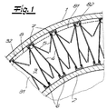
- a jacket of a storage container for radioactive objects which initially consist of a metallic Outer jacket 1 and a concentrically arranged metallic inner jacket 2 is formed. Between Outer jacket 1 and inner jacket 2 is therefore a hollow cylindrical one Gap space 3 given. Between inner jacket 2 and outer jacket 1 run heat conducting material webs 4 with flared window elements 5. These heat conduction radial webs 4 are welded to U-profiles 6, which in turn are attached to the inner jacket 2. On the outer jacket 1 are also U-profiles 7 attached to which the heat conduction radial webs 4 but are only pressed.
- the diaphragm 8 is made of open and closed profiles 81, 82 of perforated screens or sheets or wire mesh formed between the radial heat conducting webs 4 are used and are in contact with them and with them are welded.
- a concrete aggregate with a minimum grain size and then a suspension of cement, Water and additives entered. Since the diaphragm has 8 openings that is smaller than the minimum grain size only the suspension gets into the outer subspace 32.
- the diaphragm is 8th to an inner partial web arrangement 41 of heat conduction radial webs 4 and on the diaphragm 8 a supplementary outer partial web arrangement 42 placed with the inner jacket 2 is screwed.
- the diaphragm 8 the inner part web arrangement 41 and the outer part web arrangement 42 in the area of corresponding longitudinal beads 9 placed on top of each other.
- Two adjacent ones Radial partial webs of the outer partial web arrangement 42 are through an outer bridge 10 connected to each other.
- Corresponding are also two adjacent radial webs of the inner one Part web arrangement 41 through an inner bridge 11 with each other connected.
- the screw connection 12 takes place through the outer bridge 10 and the diaphragm 8 with the inner jacket 2.
- the Outer jacket 1 is under elastic deformation of the heat conduction radial webs 4 has been put on.
- the backfilling takes place in the same way as indicated above.
- composition can correspond to that in WO 98/59346 is specified.
Abstract
Description
- Fig. 1
- einen Schnitt durch einen Teil eines Behältermantels und
- Fig. 2
- einer anderen Ausführungsform.
Claims (10)
- Verfahren zum Herstellen eines Transport- und/oder Lagerbehälters für radioaktive Gegenstände, wobei ein zwischen einem metallischen Außenmantel und einem metallischen Innenmantel gebildeter hohlzylindrischer Mantelzwischenraum mit einem eine Mindestkorngröße aufweisenden Betonzuschlag und anschließend im Rest mit einer Suspension aus Zement, Wasser und Additiven verfüllt wird, dadurch gekennzeichnet, dass im Mantelzwischenraum mit Hilfe eines Diaphragmas, dessen Durchtrittsöffnungen kleiner als die Mindestkorngröße sind, zwei zueinander konzentrische Teilräume gebildet werden und der Betonzuschlag sowie die Suspension jeweils nur in einen der beiden Teilräume eingegeben werden.
- Verfahren nach Anspruch 1, dadurch gekennzeichnet, dass das Diaphragma aus Lochsieben oder -blechen oder Drahtgeflecht gebildet wird.
- Verfahren nach Anspruch 1 oder 2, dadurch gekennzeichnet, dass das Diaphragma Durchtrittsöffnungen mit einer Öffnungsweite zwischen 2 und 4 mm aufweist.
- Verfahren nach einem der Ansprüche 1 bis 3, dadurch gekennzeichnet, dass das Diaphragma durch Einführen von offenen und/oder geschlossenen Diaphragmaprofilen zwischen Wärmeleitungsradialstege gebildet wird, die zwischen Innenmantel und Außenmantel verlaufen und an denen die Diaphragmaprofile anliegen.
- Verfahren nach einem der Ansprüche 1 bis 3, dadurch gekennzeichnet, dass das Diaphragma auf eine innere Teilsteganordnung von Wärmeleitungsradialstegen, die zwischen Innenmantel und Außenmantel verlaufen, und auf das Diaphragma eine ergänzende äußere Teilsteganordung aufgesetzt wird, die mit dem Innenmantel verschraubt wird.
- Verfahren nach Anspruch 5, dadurch gekennzeichnet, dass das Diaphragma, die innere Teilsteganordnung und die äußere Teilsteganordnung im Bereich von einander entsprechenden Längssicken aufeinander gesetzt werden.
- Verfahren nach Anspruch 5 oder 6, dadurch gekennzeichnet, dass jeweils zwei benachbarte Radialteilstege der äußeren Teilsteganordnung durch eine Außenbrücke miteinander verbunden sind.
- Verfahren nach einem der Ansprüche 1 bis 7, dadurch gekennzeichnet, dass das Diaphragma durch Schweißungen lagefixiert wird.
- Verfahren nach einem der Ansprüche 1 bis 8, dadurch gekennzeichnet, dass der Betonzuschlag und die Suspension in denselben Teilraum eingegeben werden.
- Verfahren nach einem der Ansprüche 1 bis 9, dadurch gekennzeichnet, dass der Betonzuschlag in den dem Innenmantel benachbarten Teilraum eingegeben wird.
Priority Applications (15)
| Application Number | Priority Date | Filing Date | Title |
|---|---|---|---|
| AT99125003T ATE227880T1 (de) | 1999-12-15 | 1999-12-15 | Verfahren zum herstellen eines transport- und/oder lagerbehälters für radioaktive gegenstände |
| DE59903429T DE59903429D1 (de) | 1999-12-15 | 1999-12-15 | Verfahren zum Herstellen eines Transport- und/oder Lagerbehälters für radioaktive Gegenstände |
| EP99125003A EP1122744B1 (de) | 1999-12-15 | 1999-12-15 | Verfahren zum Herstellen eines Transport- und/oder Lagerbehälters für radioaktive Gegenstände |
| ES99125003T ES2182452T3 (es) | 1999-12-15 | 1999-12-15 | Procedimiento para fabricar un recipiente de transporte y/o almacenamiento de objetos radiactivos. |
| TW089124260A TW483005B (en) | 1999-12-15 | 2000-11-16 | A method of manufacturing a transport and/or storage container for radioactive articles |
| US09/728,604 US6438190B2 (en) | 1999-12-15 | 2000-12-01 | Making storage/transport container for radioactive material |
| CA002327663A CA2327663A1 (en) | 1999-12-15 | 2000-12-06 | A method of manufacturing a transport and/or storage container for radioactive articles |
| EA200001160A EA002394B1 (ru) | 1999-12-15 | 2000-12-07 | Способ изготовления контейнера для транспортировки и/или хранения радиоактивных предметов |
| CZ20004597A CZ293365B6 (cs) | 1999-12-15 | 2000-12-08 | Způsob výroby přepravní a/nebo skladovací nádoby pro radioaktivní předměty |
| BG105036A BG64066B1 (bg) | 1999-12-15 | 2000-12-08 | Метод за производство на транспортен и/или складиращ контейнер за радиоактивни предмети |
| UA2000127076A UA67781C2 (uk) | 1999-12-15 | 2000-12-08 | Спосіб виготовлення контейнера для транспортування і/або зберігання радіоактивних предметів |
| SK1874-2000A SK284611B6 (sk) | 1999-12-15 | 2000-12-08 | Spôsob výroby prepravnej a/alebo skladovacej nádoby na rádioaktívne predmety |
| JP2000377626A JP4683716B2 (ja) | 1999-12-15 | 2000-12-12 | 放射性物質用の輸送容器及び/又は貯蔵容器を製造する方法 |
| KR1020000075393A KR100746929B1 (ko) | 1999-12-15 | 2000-12-12 | 방사성 물품 수송 및/또는 저장 용기의 제조 방법 |
| CNB001356852A CN1152387C (zh) | 1999-12-15 | 2000-12-15 | 制造放射性物体的运输和/或贮存容器的方法 |
Applications Claiming Priority (1)
| Application Number | Priority Date | Filing Date | Title |
|---|---|---|---|
| EP99125003A EP1122744B1 (de) | 1999-12-15 | 1999-12-15 | Verfahren zum Herstellen eines Transport- und/oder Lagerbehälters für radioaktive Gegenstände |
Publications (2)
| Publication Number | Publication Date |
|---|---|
| EP1122744A1 true EP1122744A1 (de) | 2001-08-08 |
| EP1122744B1 EP1122744B1 (de) | 2002-11-13 |
Family
ID=8239616
Family Applications (1)
| Application Number | Title | Priority Date | Filing Date |
|---|---|---|---|
| EP99125003A Expired - Lifetime EP1122744B1 (de) | 1999-12-15 | 1999-12-15 | Verfahren zum Herstellen eines Transport- und/oder Lagerbehälters für radioaktive Gegenstände |
Country Status (15)
| Country | Link |
|---|---|
| US (1) | US6438190B2 (de) |
| EP (1) | EP1122744B1 (de) |
| JP (1) | JP4683716B2 (de) |
| KR (1) | KR100746929B1 (de) |
| CN (1) | CN1152387C (de) |
| AT (1) | ATE227880T1 (de) |
| BG (1) | BG64066B1 (de) |
| CA (1) | CA2327663A1 (de) |
| CZ (1) | CZ293365B6 (de) |
| DE (1) | DE59903429D1 (de) |
| EA (1) | EA002394B1 (de) |
| ES (1) | ES2182452T3 (de) |
| SK (1) | SK284611B6 (de) |
| TW (1) | TW483005B (de) |
| UA (1) | UA67781C2 (de) |
Families Citing this family (13)
| Publication number | Priority date | Publication date | Assignee | Title |
|---|---|---|---|---|
| SE516262C2 (sv) * | 2000-04-11 | 2001-12-10 | Oyster Int Nv | Sätt för framställning av förvaringsbehållare för kärnbränsle och anläggning för utförande av sättet |
| JP3416657B2 (ja) * | 2001-01-25 | 2003-06-16 | 三菱重工業株式会社 | キャスクおよびキャスクの製造方法 |
| US7014059B2 (en) * | 2002-05-17 | 2006-03-21 | Master Lite Security Products, Inc. | Explosion resistant waste container |
| EP1418594A1 (de) * | 2002-11-09 | 2004-05-12 | GNB Gesellschaft für Nuklear-Behälter mbH | Transport- und/oder Lagerbehälter für wärmeentwickelnde radioaktive Elemente |
| US7199375B2 (en) * | 2004-10-12 | 2007-04-03 | Bard Brachytherapy, Inc. | Radiation shielding container that encloses a vial of one or more radioactive seeds |
| FR2915307B1 (fr) * | 2007-04-18 | 2013-04-19 | Tn Int | Conteneur pour le transport et/ou stockage de matieres nucleaires, le conteneur comprenant une structure mobile de conduction thermique. |
| NO336476B1 (no) * | 2009-03-11 | 2015-09-07 | Mezonic As | En fremgangsmåte og et anlegg for produksjon av en lagringsbeholder for å lagring av nukleærstrålings-materiale |
| FR2961942B1 (fr) * | 2010-06-25 | 2014-04-11 | Tn Int | Conteneur pour le transport et/ou l'entreposage de matieres radioactives |
| CN102314954A (zh) * | 2011-09-06 | 2012-01-11 | 原子高科股份有限公司 | 一种核反应堆启动用一次中子源部件的储存运输容器 |
| KR101527141B1 (ko) * | 2013-11-01 | 2015-06-10 | 주식회사 포스코 | 캐스크용 열전달 핀 |
| CN104751925B (zh) * | 2013-12-29 | 2017-09-29 | 西安核设备有限公司 | 一种cnfc‑3g新燃料运输容器制造方法 |
| US10633163B1 (en) * | 2018-01-24 | 2020-04-28 | William M. Arnold | Transport container for radioactive material |
| CN108335765B (zh) * | 2018-01-29 | 2021-03-12 | 中广核工程有限公司 | 核电厂乏燃料干式贮存用燃料贮罐 |
Citations (7)
| Publication number | Priority date | Publication date | Assignee | Title |
|---|---|---|---|---|
| US4123392A (en) * | 1972-04-13 | 1978-10-31 | Chemtree Corporation | Non-combustible nuclear radiation shields with high hydrogen content |
| SU961971A2 (ru) * | 1981-03-26 | 1982-09-30 | Всесоюзный Ордена Трудового Красного Знамени Научно-Исследовательский Институт Гидротехники Им.Б.Е.Веденеева | Устройство дл образовани полостей в издели х из бетонных смесей |
| EP0128418A1 (de) * | 1983-06-11 | 1984-12-19 | TRANSNUKLEAR GmbH | Betonbehälter zur Aufnahme bioschädlicher Stoffe |
| JPH02269998A (ja) * | 1989-01-11 | 1990-11-05 | Mitsubishi Heavy Ind Ltd | 放射線遮蔽壁構造 |
| JPH09101387A (ja) * | 1995-10-03 | 1997-04-15 | Toshiba Corp | 原子炉格納容器 |
| JPH09257995A (ja) * | 1996-03-22 | 1997-10-03 | Ishikawajima Harima Heavy Ind Co Ltd | 固体廃棄物の収納方法及び固体廃棄物収納体 |
| DE19725922A1 (de) * | 1997-06-19 | 1998-12-24 | Gnb Gmbh | Verfahren zur Herstellung eines Behälters sowie ein Behälter selbst |
Family Cites Families (15)
| Publication number | Priority date | Publication date | Assignee | Title |
|---|---|---|---|---|
| DE2065863B2 (de) * | 1969-08-13 | 1981-07-16 | Transnucléaire, Société pour les Transports de l'Industrie Nucléaire, Paris | Behälter für die Lagerung und den Transport von radioaktiven Materialien |
| FR2055982A5 (en) * | 1969-08-13 | 1971-05-14 | Transnucleaire | Storage and transport container for a - radioactive materials |
| IT1016901B (it) * | 1973-05-25 | 1977-06-20 | Cnen | Contenitore per il trasporto di materiale fissile allo stato so lido agglomerato o sotto forma di polvere |
| US4058479A (en) * | 1975-05-12 | 1977-11-15 | Aerojet-General Corporation | Filter-lined container for hazardous solids |
| US4257912A (en) * | 1978-06-12 | 1981-03-24 | Westinghouse Electric Corp. | Concrete encapsulation for spent nuclear fuel storage |
| DE2831646A1 (de) * | 1978-07-19 | 1980-01-31 | Transnuklear Gmbh | Abschirmbehaelter fuer den transport und die lagerung bestrahlter brennelemente |
| GB2096046B (en) * | 1981-04-06 | 1984-10-24 | British Nuclear Fuels Ltd | Transport and storage flask for nuclear fuel |
| US4845372A (en) * | 1984-07-05 | 1989-07-04 | Westinghouse Electric Corp. | Nuclear waste packing module |
| JPH03267799A (ja) * | 1990-03-16 | 1991-11-28 | Ishikawajima Harima Heavy Ind Co Ltd | 放射性廃棄物の固化処理方法及び放射性廃棄物固化体 |
| JPH0436697A (ja) * | 1990-05-31 | 1992-02-06 | Kobe Steel Ltd | 使用済燃料の輸送・貯蔵容器およびその製造方法 |
| JPH052098A (ja) * | 1991-06-25 | 1993-01-08 | Nkk Corp | 放射性廃棄物の収納用容器 |
| US5402455A (en) * | 1994-01-06 | 1995-03-28 | Westinghouse Electric Corporation | Waste containment composite |
| US5545796A (en) * | 1994-02-25 | 1996-08-13 | Scientific Ecology Group | Article made out of radioactive or hazardous waste and a method of making the same |
| US5786611A (en) * | 1995-01-23 | 1998-07-28 | Lockheed Idaho Technologies Company | Radiation shielding composition |
| US5819186A (en) * | 1996-04-26 | 1998-10-06 | Stephens; Patrick J. | Cellular grout radiation barrier |
-
1999
- 1999-12-15 EP EP99125003A patent/EP1122744B1/de not_active Expired - Lifetime
- 1999-12-15 AT AT99125003T patent/ATE227880T1/de not_active IP Right Cessation
- 1999-12-15 DE DE59903429T patent/DE59903429D1/de not_active Expired - Lifetime
- 1999-12-15 ES ES99125003T patent/ES2182452T3/es not_active Expired - Lifetime
-
2000
- 2000-11-16 TW TW089124260A patent/TW483005B/zh not_active IP Right Cessation
- 2000-12-01 US US09/728,604 patent/US6438190B2/en not_active Expired - Fee Related
- 2000-12-06 CA CA002327663A patent/CA2327663A1/en not_active Abandoned
- 2000-12-07 EA EA200001160A patent/EA002394B1/ru not_active IP Right Cessation
- 2000-12-08 CZ CZ20004597A patent/CZ293365B6/cs not_active IP Right Cessation
- 2000-12-08 UA UA2000127076A patent/UA67781C2/uk unknown
- 2000-12-08 BG BG105036A patent/BG64066B1/bg unknown
- 2000-12-08 SK SK1874-2000A patent/SK284611B6/sk not_active IP Right Cessation
- 2000-12-12 KR KR1020000075393A patent/KR100746929B1/ko not_active IP Right Cessation
- 2000-12-12 JP JP2000377626A patent/JP4683716B2/ja not_active Expired - Fee Related
- 2000-12-15 CN CNB001356852A patent/CN1152387C/zh not_active Expired - Fee Related
Patent Citations (7)
| Publication number | Priority date | Publication date | Assignee | Title |
|---|---|---|---|---|
| US4123392A (en) * | 1972-04-13 | 1978-10-31 | Chemtree Corporation | Non-combustible nuclear radiation shields with high hydrogen content |
| SU961971A2 (ru) * | 1981-03-26 | 1982-09-30 | Всесоюзный Ордена Трудового Красного Знамени Научно-Исследовательский Институт Гидротехники Им.Б.Е.Веденеева | Устройство дл образовани полостей в издели х из бетонных смесей |
| EP0128418A1 (de) * | 1983-06-11 | 1984-12-19 | TRANSNUKLEAR GmbH | Betonbehälter zur Aufnahme bioschädlicher Stoffe |
| JPH02269998A (ja) * | 1989-01-11 | 1990-11-05 | Mitsubishi Heavy Ind Ltd | 放射線遮蔽壁構造 |
| JPH09101387A (ja) * | 1995-10-03 | 1997-04-15 | Toshiba Corp | 原子炉格納容器 |
| JPH09257995A (ja) * | 1996-03-22 | 1997-10-03 | Ishikawajima Harima Heavy Ind Co Ltd | 固体廃棄物の収納方法及び固体廃棄物収納体 |
| DE19725922A1 (de) * | 1997-06-19 | 1998-12-24 | Gnb Gmbh | Verfahren zur Herstellung eines Behälters sowie ein Behälter selbst |
Non-Patent Citations (4)
| Title |
|---|
| DATABASE WPI Section Ch Week 198331, Derwent World Patents Index; Class L02, AN 1983-727910, XP002134121 * |
| PATENT ABSTRACTS OF JAPAN vol. 015, no. 030 (P - 1157) 24 January 1991 (1991-01-24) * |
| PATENT ABSTRACTS OF JAPAN vol. 1997, no. 08 29 August 1997 (1997-08-29) * |
| PATENT ABSTRACTS OF JAPAN vol. 1998, no. 02 30 January 1998 (1998-01-30) * |
Also Published As
| Publication number | Publication date |
|---|---|
| JP4683716B2 (ja) | 2011-05-18 |
| KR100746929B1 (ko) | 2007-08-08 |
| US20010021237A1 (en) | 2001-09-13 |
| BG105036A (en) | 2001-07-31 |
| CZ20004597A3 (cs) | 2001-08-15 |
| EA200001160A1 (ru) | 2001-06-25 |
| CN1152387C (zh) | 2004-06-02 |
| EP1122744B1 (de) | 2002-11-13 |
| CN1300079A (zh) | 2001-06-20 |
| DE59903429D1 (de) | 2002-12-19 |
| JP2001201590A (ja) | 2001-07-27 |
| ES2182452T3 (es) | 2003-03-01 |
| ATE227880T1 (de) | 2002-11-15 |
| SK284611B6 (sk) | 2005-07-01 |
| US6438190B2 (en) | 2002-08-20 |
| KR20010062330A (ko) | 2001-07-07 |
| BG64066B1 (bg) | 2003-11-28 |
| EA002394B1 (ru) | 2002-04-25 |
| SK18742000A3 (sk) | 2001-10-08 |
| UA67781C2 (uk) | 2004-07-15 |
| CA2327663A1 (en) | 2001-06-15 |
| CZ293365B6 (cs) | 2004-04-14 |
| TW483005B (en) | 2002-04-11 |
Similar Documents
| Publication | Publication Date | Title |
|---|---|---|
| EP1122744B1 (de) | Verfahren zum Herstellen eines Transport- und/oder Lagerbehälters für radioaktive Gegenstände | |
| DE2652259C2 (de) | Rohrförmiger Behälter zum Aufnehmen und Lagern verbrauchter Kernbrennstoffelemente in einem Abklingbecken und Verfahren zum Herstellen des Behälters | |
| EP2204820B1 (de) | Strahlenschutzkammer | |
| DE3624318A1 (de) | Kernreaktor-regelstab | |
| DE19625643C2 (de) | Tür | |
| DE2942656A1 (de) | Geruest zur lagerung von verbrauchtem radioaktivem brennstoff | |
| EP0345793B1 (de) | Verwendung eines Streckmetallkörpers als brandschutztechnischer Filter | |
| DE19725922C2 (de) | Verfahren zur Herstellung eines Behälters | |
| DE69931455T2 (de) | Druckbehälter für einen Druckwasserreaktor mit zugehöriger Vorrichtung zur Beruhigung der Kühlwasserströmung im Behälterboden | |
| DE2529778B2 (de) | Sicherheitstuer | |
| EP2145365B1 (de) | Schottvorrichtung für eine stromverteilereinheit | |
| DE2111349A1 (de) | Kernreaktorbrennelement | |
| DE3712592A1 (de) | Tuer | |
| DE2724301C2 (de) | Brennelementlager | |
| DE2853357A1 (de) | Doppelwandiges panzergehaeuse | |
| DE2357633C3 (de) | Feuerfester Behälter | |
| DE3131125C2 (de) | Abschirmtransport- und/oder Abschirmlagerbehälter für bestrahlte Kernreaktorbr ennelemente | |
| DE102016221897A1 (de) | Brennelement und kerntechnische Anlage | |
| EP0903756B1 (de) | Vorrichtung zum Abschirmen einer Fluid-Wanddurchführung gegen hochenergetische elektromagnetische Strahlung, Kernstrahlung oder Korpuskularstrahlung | |
| DE19628362C1 (de) | Verfahren zum Transport und zur Lagerung von abgebrannten Brennelementen und Neutronenabsorber für die Durchführung des Verfahrens | |
| DD240090A1 (de) | Wand- und/oder deckenkonstruktion fuer strahlengefaehrdete/strahlenbelastete raeume | |
| DE1489753C (de) | Von Öffnungen durchbrochene doppel wandige Metallplatte fur Atomkernreaktoren | |
| DE202020105181U1 (de) | Mehrfachschalldämmungspartition | |
| WO2004003933A2 (de) | Brennstabbündel für einen druckwasserkernreaktor | |
| DE8206129U1 (de) | Auskleidung fuer abwasserrohre |
Legal Events
| Date | Code | Title | Description |
|---|---|---|---|
| PUAI | Public reference made under article 153(3) epc to a published international application that has entered the european phase |
Free format text: ORIGINAL CODE: 0009012 |
|
| 17P | Request for examination filed |
Effective date: 20000608 |
|
| AK | Designated contracting states |
Kind code of ref document: A1 Designated state(s): AT BE CH CY DE DK ES FI FR GB GR IE IT LI LU MC NL PT SE |
|
| AX | Request for extension of the european patent |
Free format text: AL;LT PAYMENT 20000830;LV;MK;RO;SI |
|
| AKX | Designation fees paid |
Free format text: AT BE CH CY DE DK ES FI FR GB GR IE IT LI LU MC NL PT SE |
|
| AXX | Extension fees paid |
Free format text: LT PAYMENT 20000830 |
|
| GRAG | Despatch of communication of intention to grant |
Free format text: ORIGINAL CODE: EPIDOS AGRA |
|
| GRAG | Despatch of communication of intention to grant |
Free format text: ORIGINAL CODE: EPIDOS AGRA |
|
| GRAH | Despatch of communication of intention to grant a patent |
Free format text: ORIGINAL CODE: EPIDOS IGRA |
|
| 17Q | First examination report despatched |
Effective date: 20020517 |
|
| GRAH | Despatch of communication of intention to grant a patent |
Free format text: ORIGINAL CODE: EPIDOS IGRA |
|
| GRAA | (expected) grant |
Free format text: ORIGINAL CODE: 0009210 |
|
| AK | Designated contracting states |
Kind code of ref document: B1 Designated state(s): AT BE CH CY DE DK ES FI FR GB GR IE IT LI LU MC NL PT SE |
|
| AX | Request for extension of the european patent |
Free format text: LT PAYMENT 20000830 |
|
| PG25 | Lapsed in a contracting state [announced via postgrant information from national office to epo] |
Ref country code: IE Free format text: LAPSE BECAUSE OF FAILURE TO SUBMIT A TRANSLATION OF THE DESCRIPTION OR TO PAY THE FEE WITHIN THE PRESCRIBED TIME-LIMIT Effective date: 20021113 Ref country code: GR Free format text: LAPSE BECAUSE OF FAILURE TO SUBMIT A TRANSLATION OF THE DESCRIPTION OR TO PAY THE FEE WITHIN THE PRESCRIBED TIME-LIMIT Effective date: 20021113 Ref country code: FI Free format text: LAPSE BECAUSE OF FAILURE TO SUBMIT A TRANSLATION OF THE DESCRIPTION OR TO PAY THE FEE WITHIN THE PRESCRIBED TIME-LIMIT Effective date: 20021113 |
|
| REF | Corresponds to: |
Ref document number: 227880 Country of ref document: AT Date of ref document: 20021115 Kind code of ref document: T |
|
| REG | Reference to a national code |
Ref country code: GB Ref legal event code: FG4D Free format text: NOT ENGLISH |
|
| REG | Reference to a national code |
Ref country code: CH Ref legal event code: EP |
|
| REG | Reference to a national code |
Ref country code: CH Ref legal event code: NV Representative=s name: KELLER & PARTNER PATENTANWAELTE AG |
|
| REG | Reference to a national code |
Ref country code: IE Ref legal event code: FG4D Free format text: GERMAN |
|
| PG25 | Lapsed in a contracting state [announced via postgrant information from national office to epo] |
Ref country code: LU Free format text: LAPSE BECAUSE OF NON-PAYMENT OF DUE FEES Effective date: 20021215 Ref country code: AT Free format text: LAPSE BECAUSE OF NON-PAYMENT OF DUE FEES Effective date: 20021215 |
|
| REF | Corresponds to: |
Ref document number: 59903429 Country of ref document: DE Date of ref document: 20021219 |
|
| GBT | Gb: translation of ep patent filed (gb section 77(6)(a)/1977) |
Effective date: 20021203 |
|
| PG25 | Lapsed in a contracting state [announced via postgrant information from national office to epo] |
Ref country code: CY Free format text: LAPSE BECAUSE OF FAILURE TO SUBMIT A TRANSLATION OF THE DESCRIPTION OR TO PAY THE FEE WITHIN THE PRESCRIBED TIME-LIMIT Effective date: 20021231 |
|
| PG25 | Lapsed in a contracting state [announced via postgrant information from national office to epo] |
Ref country code: SE Free format text: LAPSE BECAUSE OF FAILURE TO SUBMIT A TRANSLATION OF THE DESCRIPTION OR TO PAY THE FEE WITHIN THE PRESCRIBED TIME-LIMIT Effective date: 20030213 Ref country code: PT Free format text: LAPSE BECAUSE OF FAILURE TO SUBMIT A TRANSLATION OF THE DESCRIPTION OR TO PAY THE FEE WITHIN THE PRESCRIBED TIME-LIMIT Effective date: 20030213 Ref country code: DK Free format text: LAPSE BECAUSE OF FAILURE TO SUBMIT A TRANSLATION OF THE DESCRIPTION OR TO PAY THE FEE WITHIN THE PRESCRIBED TIME-LIMIT Effective date: 20030213 |
|
| REG | Reference to a national code |
Ref country code: ES Ref legal event code: FG2A Ref document number: 2182452 Country of ref document: ES Kind code of ref document: T3 |
|
| ET | Fr: translation filed | ||
| PG25 | Lapsed in a contracting state [announced via postgrant information from national office to epo] |
Ref country code: MC Free format text: LAPSE BECAUSE OF NON-PAYMENT OF DUE FEES Effective date: 20030701 |
|
| REG | Reference to a national code |
Ref country code: IE Ref legal event code: FD4D Ref document number: 1122744E Country of ref document: IE |
|
| PLBE | No opposition filed within time limit |
Free format text: ORIGINAL CODE: 0009261 |
|
| STAA | Information on the status of an ep patent application or granted ep patent |
Free format text: STATUS: NO OPPOSITION FILED WITHIN TIME LIMIT |
|
| 26N | No opposition filed |
Effective date: 20030814 |
|
| PG25 | Lapsed in a contracting state [announced via postgrant information from national office to epo] |
Ref country code: GB Free format text: LAPSE BECAUSE OF NON-PAYMENT OF DUE FEES Effective date: 20031215 |
|
| PG25 | Lapsed in a contracting state [announced via postgrant information from national office to epo] |
Ref country code: NL Free format text: LAPSE BECAUSE OF NON-PAYMENT OF DUE FEES Effective date: 20040701 |
|
| GBPC | Gb: european patent ceased through non-payment of renewal fee |
Effective date: 20031215 |
|
| NLV4 | Nl: lapsed or anulled due to non-payment of the annual fee |
Effective date: 20040701 |
|
| PGFP | Annual fee paid to national office [announced via postgrant information from national office to epo] |
Ref country code: BE Payment date: 20050118 Year of fee payment: 6 |
|
| REG | Reference to a national code |
Ref country code: CH Ref legal event code: PUE Owner name: GNS GESELLSCHAFT FUER NUKLEAR-SERVICE MBH Free format text: GNB GESELLSCHAFT FUER NUKLEAR-BEHAELTER MBH#HOLLESTRASSE 7A#45127 ESSEN (DE) -TRANSFER TO- GNS GESELLSCHAFT FUER NUKLEAR-SERVICE MBH#HOLLESTRASSE 7A#45127 ESSEN (DE) |
|
| REG | Reference to a national code |
Ref country code: FR Ref legal event code: TP |
|
| PG25 | Lapsed in a contracting state [announced via postgrant information from national office to epo] |
Ref country code: BE Free format text: LAPSE BECAUSE OF NON-PAYMENT OF DUE FEES Effective date: 20051231 |
|
| BERE | Be: lapsed |
Owner name: G.- FUR NUKLEAR-BEHALTER M.B.H. *GNB Effective date: 20051231 |
|
| REG | Reference to a national code |
Ref country code: CH Ref legal event code: PCAR Free format text: NEW ADDRESS: EIGERSTRASSE 2 POSTFACH, 3000 BERN 14 (CH) |
|
| REG | Reference to a national code |
Ref country code: FR Ref legal event code: PLFP Year of fee payment: 17 |
|
| REG | Reference to a national code |
Ref country code: FR Ref legal event code: PLFP Year of fee payment: 18 |
|
| PGFP | Annual fee paid to national office [announced via postgrant information from national office to epo] |
Ref country code: CH Payment date: 20161221 Year of fee payment: 18 |
|
| PGFP | Annual fee paid to national office [announced via postgrant information from national office to epo] |
Ref country code: FR Payment date: 20161222 Year of fee payment: 18 Ref country code: ES Payment date: 20161213 Year of fee payment: 18 |
|
| PGFP | Annual fee paid to national office [announced via postgrant information from national office to epo] |
Ref country code: DE Payment date: 20161229 Year of fee payment: 18 |
|
| PGFP | Annual fee paid to national office [announced via postgrant information from national office to epo] |
Ref country code: IT Payment date: 20161223 Year of fee payment: 18 |
|
| REG | Reference to a national code |
Ref country code: DE Ref legal event code: R119 Ref document number: 59903429 Country of ref document: DE |
|
| REG | Reference to a national code |
Ref country code: LT Ref legal event code: MM9D Effective date: 20171215 |
|
| REG | Reference to a national code |
Ref country code: CH Ref legal event code: PL |
|
| REG | Reference to a national code |
Ref country code: FR Ref legal event code: ST Effective date: 20180831 |
|
| PG25 | Lapsed in a contracting state [announced via postgrant information from national office to epo] |
Ref country code: DE Free format text: LAPSE BECAUSE OF NON-PAYMENT OF DUE FEES Effective date: 20180703 Ref country code: IT Free format text: LAPSE BECAUSE OF NON-PAYMENT OF DUE FEES Effective date: 20171215 Ref country code: FR Free format text: LAPSE BECAUSE OF NON-PAYMENT OF DUE FEES Effective date: 20180102 |
|
| PG25 | Lapsed in a contracting state [announced via postgrant information from national office to epo] |
Ref country code: LI Free format text: LAPSE BECAUSE OF NON-PAYMENT OF DUE FEES Effective date: 20171231 Ref country code: CH Free format text: LAPSE BECAUSE OF NON-PAYMENT OF DUE FEES Effective date: 20171231 |
|
| REG | Reference to a national code |
Ref country code: ES Ref legal event code: FD2A Effective date: 20190703 |
|
| PG25 | Lapsed in a contracting state [announced via postgrant information from national office to epo] |
Ref country code: ES Free format text: LAPSE BECAUSE OF NON-PAYMENT OF DUE FEES Effective date: 20171216 |