EP1126467A1 - Synchronous counter for electronic memories - Google Patents
Synchronous counter for electronic memories Download PDFInfo
- Publication number
- EP1126467A1 EP1126467A1 EP00830100A EP00830100A EP1126467A1 EP 1126467 A1 EP1126467 A1 EP 1126467A1 EP 00830100 A EP00830100 A EP 00830100A EP 00830100 A EP00830100 A EP 00830100A EP 1126467 A1 EP1126467 A1 EP 1126467A1
- Authority
- EP
- European Patent Office
- Prior art keywords
- counter
- signal
- stages
- circuit according
- address
- Prior art date
- Legal status (The legal status is an assumption and is not a legal conclusion. Google has not performed a legal analysis and makes no representation as to the accuracy of the status listed.)
- Granted
Links
Images


Classifications
-
- H—ELECTRICITY
- H03—ELECTRONIC CIRCUITRY
- H03K—PULSE TECHNIQUE
- H03K23/00—Pulse counters comprising counting chains; Frequency dividers comprising counting chains
- H03K23/64—Pulse counters comprising counting chains; Frequency dividers comprising counting chains with a base or radix other than a power of two
- H03K23/66—Pulse counters comprising counting chains; Frequency dividers comprising counting chains with a base or radix other than a power of two with a variable counting base, e.g. by presetting or by adding or suppressing pulses
- H03K23/665—Pulse counters comprising counting chains; Frequency dividers comprising counting chains with a base or radix other than a power of two with a variable counting base, e.g. by presetting or by adding or suppressing pulses by presetting
-
- G—PHYSICS
- G11—INFORMATION STORAGE
- G11C—STATIC STORES
- G11C7/00—Arrangements for writing information into, or reading information out from, a digital store
- G11C7/10—Input/output [I/O] data interface arrangements, e.g. I/O data control circuits, I/O data buffers
- G11C7/1015—Read-write modes for single port memories, i.e. having either a random port or a serial port
- G11C7/1018—Serial bit line access mode, e.g. using bit line address shift registers, bit line address counters, bit line burst counters
-
- G—PHYSICS
- G11—INFORMATION STORAGE
- G11C—STATIC STORES
- G11C8/00—Arrangements for selecting an address in a digital store
- G11C8/04—Arrangements for selecting an address in a digital store using a sequential addressing device, e.g. shift register, counter
Definitions
- the present invention relates to a synchronous counter for electronic memories. More particularly, the invention relates to a fast synchronous counter for memories which is faster than conventional counters.
- the structures that compose the memory are constituted so as to ensure a normal read cycle which begins with a request stimulus (switching of the addressing lines) and ends with the extraction of the data related to the addressed memory location.
- these conventional memories are capable of performing only one reading process at a time, with the particularity that each read cycle is identical to every other in terms of response of the memory.
- a read cycle for a memory of a conventional type is penalized by long read times for each read cycle.
- Each read cycle has the same duration as all other read cycles.
- the overall duration of a read cycle is given by the sum of elementary signal propagation times, and in particular:
- the read times for each read cycle remain unchanged even if the new location to be read is adjacent to a location read in the directly preceding cycle. In this case it would be advantageous to be able to utilize to the advantage of read speed the fact that the new read occurs in a position which is physically close to the preceding read position.
- the aim of the present invention is to provide a synchronous counter for electronic memories which can be used with memories of the interleaved type and thus can be synchronized with an external control signal for reading the memory.
- an object of the present invention is to provide a synchronous counter for electronic memories whose configuration can be defined immediately from outside at each count start.
- Another object of the present invention is to provide a synchronous counter for electronic memories which can be updated internally during counting.
- Another object of the present invention is to provide a synchronous counter for electronic memories which is functionally insensitive to external stimuli during counting.
- Another object of the present invention is to provide a synchronous counter for electronic memories whose functionality can be monitored from outside the memory without requiring additional circuits.
- Another object of the present invention is to provide a synchronous counter for electronic memories which is protected against unwanted loading of addresses which are not expressly intended for the memory.
- Another object of the present invention is to provide a synchronous counter for electronic memories which allows to assign the maximum possible time for carry calculation, maximizing the operating frequency.
- Another object of the present invention is to provide a synchronous counter for electronic memories in which the corresponding control signals are not simultaneously active.
- Another object of the present invention is to provide a synchronous counter for electronic memories which is highly reliable, relatively easy to manufacture and at competitive costs.
- a memory counter circuit comprising a plurality of mutually connected counter stages, characterized in that it comprises:
- the memory uses interleaved read streams which allow to reduce, by at least halving it, the access time and the cycle time.
- the memory array is advantageously organized into two functionally identical banks capable of allowing the development of two simultaneous read processes.
- the two read processes which are simultaneously active but independent, are appropriately synchronized with respect to each other and are advantageously concatenated so as to ensure the evolution of the read cycles on two banks in an interleaved mode and so as to allow (without any reduction in the read intervals) halving of the signal propagation times and therefore, ultimately, a much faster reading of the memory cells.
- Each one of the separate memory banks has its own independent addressing system, but at the same time the addressing systems are mutually compatible and can be mutually synchronized with an external timing signal which sets their timing.
- the addressing system must have the characteristic of being directly configurable from outside the memory, but also of having an entirely autonomous updating capability, handled inside said memory, under the control of a stimulus which is activated externally to the memory.
- Adjacency allows the possibility of sequential reads, which are inherently associated with the concept of predictability of the subsequent location to be read.
- interleaved memory type which is characterized by interleaved read streams.
- This approach allows to reduce (and at least halve) both the time for access to the memory and the cycle time.
- the memory array is conveniently organized into two separate memory banks which are functionally dual and allow the simultaneous existence of two read processes.
- the two simultaneously active but independent read processes are mutually appropriately synchronized and concatenated so as to ensure the evolution of the read cycles on the two separate banks in interlaced mode and so as to allow (without any reduction in the read intervals) halving of the read signal propagation times.
- the data extracted alternatively from the two memory banks, allow to reduce the overall read times.
- the two separate banks that compose the memory of the interleaved type each have their own independent addressing system, but at the same time the addressing systems can be mutually synchronized by means of an external timing signal which regulates their evolution times.
- the addressing system must have the characteristic of being directly configurable externally but also of having the possibility of autonomous updating, handled inside the memory itself, under the control of a stimulus activated from outside.
- the counter according to the invention can conveniently be isolated from external stimuli and can be reconfigured autonomously whenever it is appropriately stimulated.
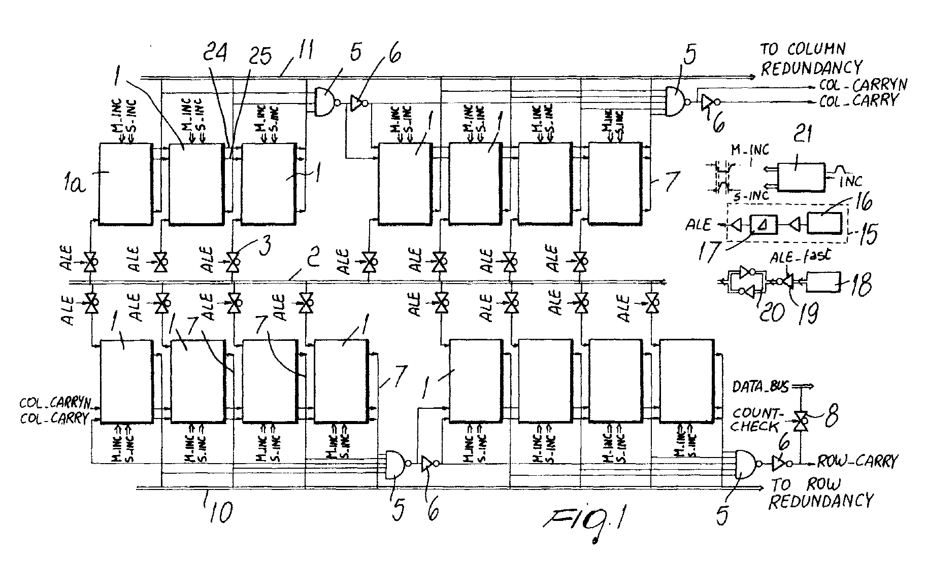
- the base counter is constituted by a plurality of stages N, each designated by the reference numeral 1, in which the first stage is designated by the reference numeral la.
- the structure of the first stage can be particular, as described in detail hereinafter.
- connection means 3 which are conveniently constituted for example by a pass gate, driven by an address latch enable signal ALE.
- the signal ALE is generated by an appropriately provided structure described hereinafter.
- connection between the internal address bus 2 and the stages 1 of the counter therefore occurs from the bus 2 toward each stage through the pass gates 3.
- Each counter stage is further connected to a fast carry structure which is formed by a NAND gate 5 to which an inverter 6 is cascade-connected.
- Output lines 7 from each counter stage 1 each constitute an input of the NAND gate 5 whose output is sent to the inverter 6 and to a successive stage 1 of the counter.
- the stages of the counter are divided into blocks of, for example, three, four, four and four, and there are four NAND gates 5 and a matching number of inverters 6.
- the first group of three counter stages 1 has a corresponding NAND gate 5 to which it sends its outputs, and the output of the NAND gate 5 is sent to the first counter stage 1 of the second group of four counter stages, whose outputs are in turn sent to a second NAND gate 5 to which an inverter 6 is in turn cascade-connected.
- the second group of four counter stages has a third NAND gate 5 to which its outputs (lines 7) are sent, and the output of the third NAND gate 5 is sent to the first counter stage 1 of the third group of four counter stages.
- the third group of four counter stages has a fourth NAND gate 5 to which it sends its outputs.
- the fast carry structures are used to reduce the carry propagation time.
- the output of the second NAND gate 5 (and of the corresponding inverter 6) and the output of the fourth NAND gate 5 and of the corresponding inverter 6 are, respectively, a column carry signal col-carry and its inverted equivalent col-carryen, and a row carry signal row-carry.
- the output of the fourth inverter 6 cascade-connected to the fourth NAND gate 5 is further sent to a further pass-gate 8, which is driven by a signal count-check which is used during counter testing before the device is deemed suitable for the intended operation.
- the pass-gate 8 is directly interfaced with a data bus data-bus, which is the main bus of the memory and transfers all the data to and from the memory.
- the lines 7 in output from each counter stage 1 are further directly interfaced with an internal row address bus 10 and with an internal column address bus 11, which are respectively connected to row and column redundancy structures which are not shown in the figures.
- the signal ALE address latch enable
- ALE address latch enable
- circuit structure 15 which generates, from a signal ALE 16 which is external to the memory, a signal ALE-fast and, after an appropriate delay 17, generates a signal ALE which is true, i.e., is a genuine address latch enable signal which is not dictated by false stimuli that reach the memory.
- the structure 15 for generating the signal ALE is the subject of a co-pending Patent Application in the name of this same Applicant whose contents are assumed included herein by reference.
- the signal ALE-fast drives- the transfer of an external address 18 of the memory through an inverter 19 to a latch structure 20, where the external address 18 is stored and then sent on the internal address bus 2.
- the signal ALE i.e., the signal ALE which is assuredly intended for the memory, is instead used to drive the transfer of the external address 18 that is present on the address bus 2 from said bus 2 to each counter stage 1.
- Figure 1 is a diagram of a counter for a memory in which, in summary, some stages 1 of the counter, specifically the stages arranged above the internal address bus 2 in the figure, are meant to count the column address, while the stages arranged below the internal bus 2 (from a graphic point of view) are dedicated to row carry.
- the two groups of stages arranged above and below the internal address bus 2, are in turn divided into two sub-groups which are mutually connected by the fast carry structures as explained earlier.
- the counter is further driven by an increment pulse INC which is generated by an appropriate circuit structure which is the subject of a co-pending Patent Application in the name of this same Applicant and is assumed included herein by reference; said pulse is input to a clock signal generation circuit 21 which emits signals M-inc and S-inc which are respectively sent to each stage 1 of the counter according to the invention.
- INC increment pulse
- the increment pulse INC is, by construction, very narrow (with respect to the interval between two successive increments), in order to allow frequency maximization, since:
- stage updating is instantaneous and simultaneous for all the stages 1.
- the clock signals M-inc and S-inc are therefore derived from the increment pulse INC and do not temporally overlap (they are not simultaneously active), in order to prevent any possibility of internal acceleration of the counter ("runaway" effects).
- Figure 2 is a diagram of the circuit 21 for generating clock signals M-inc and S-inc and the respective inverted signals M-incn and S-incn.
- Each counter stage 1 is connected to the adjacent counter stage and outputs to it an output carry signal 24 and an address signal 25, which are then transferred to the adjacent stage 1.
- the column carry signal col-carry and its inverted form col-carryn, produced by the second NAND gate 5 and by the corresponding second inverter 6, are sent in input to the first counter stage 1 of the counter stages meant to provide row carry counting, and the column carry signal col-carry is also sent as input to the third NAND gate 5.
- the counter stage la is shown in the dashed-line portion of Figure 4 and comprises two latch structures, a master one 30 and a slave one 31, which are mutually connected by way of first means for enabling connection between the latch structure 31 and the latch structure 30, designated by the reference numeral 33, and second means for enabling connection between the latch structure 30 and the latch structure 31, designated by the reference numeral 34.
- the means for enabling connection between the latch structures 31 and 30, designated by the reference numerals 33 and 34 are constituted by pass gates.
- an inverter 35 At the output of the master latch structure 30 there is provided an inverter 35.
- the enabling means 33 and 34 are respectively driven by the clock signals S-inc (S-incn) and M-inc (M-incn) explained earlier and generated by the clock signal generation circuit 21.
- the output of the first counter stage is constituted by a carry output signal carry-out, by its inverted form carry-outn, and by the address signal ADD.
- Figure 3 illustrates a stage 1 of the counter according to the invention, i.e., one of the stages that follow the first stage la.
- each counter stage 1 after the first one la has a connection between the latch structure 30 and the latch structure 31 which can occur along two mutually different paths following an inversion produced by the inverter 14.
- each counter stage after the first one has a first path between the master structure 30, constituted by means for enabling connection between the latch structure 30 and the latch structure 31, which are enabled by the presence, or absence, of an input carry carry-in; said means are designated by the reference numeral 40.
- Said connection enabling means are conveniently constituted by a pass gate.
- the second path for connection between the master structure 30 and the slave structure 31, i.e., the path from the output of the inverter 14 to the slave structure (latch) 11 is controlled by second connection enabling means 41, also conveniently constituted by a pass gate.
- the input carry signal carry-in is fed to the N-channel transistor of the connection enabling means 40, while the signal carry-inn (i.e. the inverted form of the preceding signal) is fed to the P-channel transistors of the first connection enabling means 40 and to the N-channel transistors of the second connection enabling means 41.
- the inverted input carry signal (carry-inn) is also input to carry forming means, conveniently constituted by a pass gate 42 and by a P-channel transistor 43 whose gate terminal receives in input the carry signal carry-in.
- the inverted input carry signal (carry-inn) is instead sent to the P-channel transistor of the pass gate 42, whose N-channel transistor is connected to the gate terminal of the P-channel transistor 43.
- the drain terminal is connected to means for buffering the output carry (carry-out) which are designated by the reference numeral 44 and emit in output the output carry.
- the inverted output carry carry-outn is instead emitted by the pass gate 42.
- the counter circuit according to the invention therefore can be configured externally by means of the external address signal at each count start, internally updated during counting, and is functionally insensitive to external stimuli during counting activity (i.e. when the signal ALE is off).
- Each stage of the counter can be updated simultaneously and instantaneously with respect to all the other stages, and the association with the fast carry network allows to reduce the carry propagation time, thus increasing the operating frequency.
- the fast carry network allows to monitor the functionality of the counter from outside.
- This particular monitoring method allows to select, at the beginning of the testing activities, the integrity of the addressing structures, limiting the long validation sequences only to the functionally addressable devices.
- the particular input stage of the counter allows two-step acquisition of an external address, driven by the signal ALE, which accordingly allows protection against improper external loading.
- the particular input stage of the counter allows to isolate internal lines of the counter, to avoid unnecessary consumption in the interface section, facilitate noise immunity and freeze the initial configuration of the bus at its first loading, so that at a generic instant both the current address and the initial address are present.
- the counter circuit according to the invention fully achieves the intended aim and objects, since it allows to achieve speed of operation, adequate insensitivity to improper loading, and the possibility to monitor its functional integrity from outside.
Abstract
Description
- address transition request detection (signal ATD);
- identification of the memory location to be read (addressing);
- selection of the paths for access to the location to be read (word line, bit line);
- pre-charging of the data lines (PC);
- evaluation of the responses of the individual memory cells by means of a sense amplifier;
- transfer of the read data to the output analysis time memories (buffer).
Claims (14)
- A memory counter circuit, comprising a plurality of mutually connected counter stages, characterized in that it comprises:an internal address bus which is interfaced with each one of said counter stages and is adapted to send an external address signal to each one of said counter stages;means for loading said external address signal onto said internal address bus;means for enabling the connection between said internal bus and each one of said counter stages, said means being driven by a true address latch enable signal;means for generating said true address latch enable signal starting from an external address latch signal and a fast address latch enable signal which is adapted to drive said means for loading the external address onto said internal address bus; andmeans for generating clock signals for synchronizing each one of said counter stages, said synchronization signals not being simultaneously active.
- The counter circuit according to claim 1, characterized in that it comprises a fast carry network with which each one of said counter stages is interfaced.
- The counter circuit according to claim 2, characterized in that said counter stages are divided into a group of counter stages which are meant to count a row carry and into a group of counter stages meant to count a column carry, the column carry being sent in input to a first one of said counter stages meant to count the row carry.
- The counter circuit according to claim 3, characterized in that each one of said groups of counter stages is in turn divided into two subgroups of counter stages which are interfaced with the fast carry network.
- The counter circuit according to claim 4, characterized in that each one of said counter stages is interfaced with a corresponding portion of said fast carry network by means of an output line.
- The counter circuit according to claim 5, characterized in that said fast carry network portion comprises a NAND gate to which an inverter is cascade-connected, each output line of each counter stage being adapted to send an address signal of said counter stage to said fast carry network portion, said address signal of said counter stage constituting an input of said NAND gate.
- The counter circuit according to claim 1, characterized in that said means for generating synchronization clock signals receive in input a signal. for the increment of said counter.
- The counter circuit according to claim 7, characterized in that said increment signal has a negligible duration with respect to the interval between two successive increment signals.
- The counter circuit according to claim 1, characterized in that each one of said counter stages sends to the counter stage adjacent thereto an output carry signal and its inverted form.
- The counter circuit according to claim 1, characterized in that said means for enabling the connection between said internal address bus and each one of said counter means comprise a pass gate for each one of said counter stages, said pass gate being driven by said true address latch enable signal.
- The counter circuit according to claim 5, characterized in that the fast carry network portion related to said counter stages meant to count said row carry is connected in output to a pass gate which is driven by a counter count check signal.
- The counter circuit according to claim 11, characterized in that said pass gate is in turn connected to an internal data bus of said memory in which said counter is inserted.
- The counter circuit according to claim 6, characterized in that each output line of each one of said counter stages is further interfaced with a redundancy bus.
- The counter circuit according to claim 1, characterized in that said means for generating the true latch enable signal comprise delay means adapted to delay said external latch enable signal.
Priority Applications (3)
| Application Number | Priority Date | Filing Date | Title |
|---|---|---|---|
| DE60041954T DE60041954D1 (en) | 2000-02-14 | 2000-02-14 | |
| EP00830100A EP1126467B1 (en) | 2000-02-14 | 2000-02-14 | Synchronous counter for electronic memories |
| US09/767,762 US6351434B2 (en) | 2000-02-14 | 2001-01-23 | Synchronous counter for electronic memories |
Applications Claiming Priority (1)
| Application Number | Priority Date | Filing Date | Title |
|---|---|---|---|
| EP00830100A EP1126467B1 (en) | 2000-02-14 | 2000-02-14 | Synchronous counter for electronic memories |
Publications (2)
| Publication Number | Publication Date |
|---|---|
| EP1126467A1 true EP1126467A1 (en) | 2001-08-22 |
| EP1126467B1 EP1126467B1 (en) | 2009-04-08 |
Family
ID=8175179
Family Applications (1)
| Application Number | Title | Priority Date | Filing Date |
|---|---|---|---|
| EP00830100A Expired - Lifetime EP1126467B1 (en) | 2000-02-14 | 2000-02-14 | Synchronous counter for electronic memories |
Country Status (3)
| Country | Link |
|---|---|
| US (1) | US6351434B2 (en) |
| EP (1) | EP1126467B1 (en) |
| DE (1) | DE60041954D1 (en) |
Cited By (1)
| Publication number | Priority date | Publication date | Assignee | Title |
|---|---|---|---|---|
| EP1884955A1 (en) * | 2006-07-28 | 2008-02-06 | STMicroelectronics S.r.l. | Address counter for nonvolatile memory device |
Families Citing this family (1)
| Publication number | Priority date | Publication date | Assignee | Title |
|---|---|---|---|---|
| EP2457417A1 (en) * | 2009-07-24 | 2012-05-30 | Koninklijke Philips Electronics N.V. | Inteconnecting grids of devices of networked control systems |
Citations (8)
| Publication number | Priority date | Publication date | Assignee | Title |
|---|---|---|---|---|
| JPS5754432A (en) * | 1980-09-19 | 1982-03-31 | Hitachi Ltd | Count data input circuit |
| JPS61281622A (en) * | 1985-06-06 | 1986-12-12 | Mitsubishi Electric Corp | Counter circuit |
| JPS62132425A (en) * | 1985-12-04 | 1987-06-15 | Nec Corp | Counter |
| JPH0213128A (en) * | 1988-06-30 | 1990-01-17 | Sharp Corp | Synchronous type programmable counter |
| US5361365A (en) * | 1989-11-06 | 1994-11-01 | Sharp Kabushiki Kaisha | Microprocessor for selectively performing cold and warm starts |
| US5561674A (en) * | 1994-05-26 | 1996-10-01 | Samsung Electronics Co., Ltd. | Synchronous counter and method for propagation carry of the same |
| US5781500A (en) * | 1996-05-06 | 1998-07-14 | Hyundai Electronics Industries Co., Ltd. | Method and circuit for generating internal pulse signals in synchronous memory |
| US5825713A (en) * | 1995-02-08 | 1998-10-20 | Samsung Electronics Co., Ltd. | Dual port memory device and a method therefor |
Family Cites Families (1)
| Publication number | Priority date | Publication date | Assignee | Title |
|---|---|---|---|---|
| JPH0437904A (en) * | 1990-06-01 | 1992-02-07 | Mitsubishi Electric Corp | Counter device |
-
2000
- 2000-02-14 DE DE60041954T patent/DE60041954D1/de not_active Expired - Lifetime
- 2000-02-14 EP EP00830100A patent/EP1126467B1/en not_active Expired - Lifetime
-
2001
- 2001-01-23 US US09/767,762 patent/US6351434B2/en not_active Expired - Fee Related
Patent Citations (8)
| Publication number | Priority date | Publication date | Assignee | Title |
|---|---|---|---|---|
| JPS5754432A (en) * | 1980-09-19 | 1982-03-31 | Hitachi Ltd | Count data input circuit |
| JPS61281622A (en) * | 1985-06-06 | 1986-12-12 | Mitsubishi Electric Corp | Counter circuit |
| JPS62132425A (en) * | 1985-12-04 | 1987-06-15 | Nec Corp | Counter |
| JPH0213128A (en) * | 1988-06-30 | 1990-01-17 | Sharp Corp | Synchronous type programmable counter |
| US5361365A (en) * | 1989-11-06 | 1994-11-01 | Sharp Kabushiki Kaisha | Microprocessor for selectively performing cold and warm starts |
| US5561674A (en) * | 1994-05-26 | 1996-10-01 | Samsung Electronics Co., Ltd. | Synchronous counter and method for propagation carry of the same |
| US5825713A (en) * | 1995-02-08 | 1998-10-20 | Samsung Electronics Co., Ltd. | Dual port memory device and a method therefor |
| US5781500A (en) * | 1996-05-06 | 1998-07-14 | Hyundai Electronics Industries Co., Ltd. | Method and circuit for generating internal pulse signals in synchronous memory |
Non-Patent Citations (4)
| Title |
|---|
| PATENT ABSTRACTS OF JAPAN vol. 006, no. 128 (E - 118) 14 July 1982 (1982-07-14) * |
| PATENT ABSTRACTS OF JAPAN vol. 011, no. 143 (E - 504) 9 May 1987 (1987-05-09) * |
| PATENT ABSTRACTS OF JAPAN vol. 011, no. 355 (E - 558) 19 November 1987 (1987-11-19) * |
| PATENT ABSTRACTS OF JAPAN vol. 014, no. 154 (E - 0907) 23 March 1990 (1990-03-23) * |
Cited By (2)
| Publication number | Priority date | Publication date | Assignee | Title |
|---|---|---|---|---|
| EP1884955A1 (en) * | 2006-07-28 | 2008-02-06 | STMicroelectronics S.r.l. | Address counter for nonvolatile memory device |
| US7558152B2 (en) | 2006-07-28 | 2009-07-07 | Hyungsang Lee | Address counter for nonvolatile memory device |
Also Published As
| Publication number | Publication date |
|---|---|
| US20010014041A1 (en) | 2001-08-16 |
| DE60041954D1 (en) | 2009-05-20 |
| EP1126467B1 (en) | 2009-04-08 |
| US6351434B2 (en) | 2002-02-26 |
Similar Documents
| Publication | Publication Date | Title |
|---|---|---|
| US9613684B2 (en) | Systems and methods involving propagating read and write address and data through multi-bank memory circuitry | |
| TWI675372B (en) | Systems and methods involving multi-bank, dual-pipe memory circuitry | |
| EP0264893B1 (en) | Semiconductor memory | |
| US6587913B2 (en) | Interleaved memory device for burst type access in synchronous read mode with the two semi-arrays independently readable in random access asynchronous mode | |
| CN114553215A (en) | System and method for testing and configuration of an FPGA | |
| KR970067341A (en) | Semiconductor memory device with improved precharge time | |
| US6470431B2 (en) | Interleaved data path and output management architecture for an interleaved memory and load pulser circuit for outputting the read data | |
| US5651128A (en) | Programmable integrated circuit memory comprising emulation means | |
| KR0143184B1 (en) | Semiconductor memory device in which data are read and written asynchronously with application of address signal | |
| EP1126467B1 (en) | Synchronous counter for electronic memories | |
| US20050210215A1 (en) | Semiconductor device permitting rapid data reading and writing between processor and memory | |
| US7504864B2 (en) | Method for controlling the evaluation time of a state machine | |
| KR20000057957A (en) | Bus driving circuit and memory device having the bus driving circuit | |
| US6191974B1 (en) | Nonvolatile semiconductor memory | |
| KR19980081085A (en) | Narrow Synchronous Delay Circuit Generates Output Signal with Different Repetition Period from Input Signal | |
| US6804756B2 (en) | Synchronization circuit for read paths of an electronic memory | |
| EP1122736B1 (en) | ATD generation in a synchronous memory | |
| US8397034B1 (en) | Multi-port arbitration system and method | |
| US7489555B2 (en) | Program-verify sensing for a multi-level cell (MLC) flash memory device | |
| US6275416B1 (en) | Pulse generator circuit, particularly for non-volatile memories | |
| KR900004814B1 (en) | Verifying device for setting up initial value of sram | |
| KR20160006482A (en) | Semiconductor device | |
| US7039838B2 (en) | Method for testing a circuit unit to be tested and test apparatus | |
| KR970011023B1 (en) | Semiconductor memory device | |
| JP2005267741A (en) | Circuit device for testing rom decoder and method for testing rom decoder |
Legal Events
| Date | Code | Title | Description |
|---|---|---|---|
| PUAI | Public reference made under article 153(3) epc to a published international application that has entered the european phase |
Free format text: ORIGINAL CODE: 0009012 |
|
| AK | Designated contracting states |
Kind code of ref document: A1 Designated state(s): AT BE CH CY DE DK ES FI FR GB GR IE IT LI LU MC NL PT SE |
|
| AX | Request for extension of the european patent |
Free format text: AL;LT;LV;MK;RO;SI |
|
| 17P | Request for examination filed |
Effective date: 20020212 |
|
| AKX | Designation fees paid |
Free format text: DE FR GB IT |
|
| 17Q | First examination report despatched |
Effective date: 20061004 |
|
| GRAP | Despatch of communication of intention to grant a patent |
Free format text: ORIGINAL CODE: EPIDOSNIGR1 |
|
| GRAS | Grant fee paid |
Free format text: ORIGINAL CODE: EPIDOSNIGR3 |
|
| GRAA | (expected) grant |
Free format text: ORIGINAL CODE: 0009210 |
|
| AK | Designated contracting states |
Kind code of ref document: B1 Designated state(s): DE FR GB IT |
|
| REG | Reference to a national code |
Ref country code: GB Ref legal event code: FG4D |
|
| REF | Corresponds to: |
Ref document number: 60041954 Country of ref document: DE Date of ref document: 20090520 Kind code of ref document: P |
|
| PLBE | No opposition filed within time limit |
Free format text: ORIGINAL CODE: 0009261 |
|
| STAA | Information on the status of an ep patent application or granted ep patent |
Free format text: STATUS: NO OPPOSITION FILED WITHIN TIME LIMIT |
|
| 26N | No opposition filed |
Effective date: 20100111 |
|
| GBPC | Gb: european patent ceased through non-payment of renewal fee |
Effective date: 20100214 |
|
| REG | Reference to a national code |
Ref country code: FR Ref legal event code: ST Effective date: 20101029 |
|
| PG25 | Lapsed in a contracting state [announced via postgrant information from national office to epo] |
Ref country code: FR Free format text: LAPSE BECAUSE OF NON-PAYMENT OF DUE FEES Effective date: 20100301 |
|
| PG25 | Lapsed in a contracting state [announced via postgrant information from national office to epo] |
Ref country code: GB Free format text: LAPSE BECAUSE OF NON-PAYMENT OF DUE FEES Effective date: 20100214 Ref country code: IT Free format text: LAPSE BECAUSE OF FAILURE TO SUBMIT A TRANSLATION OF THE DESCRIPTION OR TO PAY THE FEE WITHIN THE PRESCRIBED TIME-LIMIT Effective date: 20090408 |
|
| REG | Reference to a national code |
Ref country code: DE Ref legal event code: R082 Ref document number: 60041954 Country of ref document: DE Representative=s name: VIERING, JENTSCHURA & PARTNER, DE |
|
| REG | Reference to a national code |
Ref country code: DE Ref legal event code: R082 Ref document number: 60041954 Country of ref document: DE Representative=s name: VIERING, JENTSCHURA & PARTNER, DE Effective date: 20130211 Ref country code: DE Ref legal event code: R081 Ref document number: 60041954 Country of ref document: DE Owner name: MICRON TECHNOLOGY, INC., US Free format text: FORMER OWNER: STMICROELECTRONICS S.R.L., AGRATE BRIANZA, IT Effective date: 20130211 Ref country code: DE Ref legal event code: R081 Ref document number: 60041954 Country of ref document: DE Owner name: MICRON TECHNOLOGY, INC., BOISE, US Free format text: FORMER OWNER: STMICROELECTRONICS S.R.L., AGRATE BRIANZA, MAILAND/MILANO, IT Effective date: 20130211 Ref country code: DE Ref legal event code: R082 Ref document number: 60041954 Country of ref document: DE Representative=s name: VIERING, JENTSCHURA & PARTNER MBB PATENT- UND , DE Effective date: 20130211 |
|
| PGFP | Annual fee paid to national office [announced via postgrant information from national office to epo] |
Ref country code: DE Payment date: 20190129 Year of fee payment: 20 |
|
| REG | Reference to a national code |
Ref country code: DE Ref legal event code: R071 Ref document number: 60041954 Country of ref document: DE |