EP1129902A2 - Control system to automatically dim vehicle head lamps - Google Patents
Control system to automatically dim vehicle head lamps Download PDFInfo
- Publication number
- EP1129902A2 EP1129902A2 EP01109404A EP01109404A EP1129902A2 EP 1129902 A2 EP1129902 A2 EP 1129902A2 EP 01109404 A EP01109404 A EP 01109404A EP 01109404 A EP01109404 A EP 01109404A EP 1129902 A2 EP1129902 A2 EP 1129902A2
- Authority
- EP
- European Patent Office
- Prior art keywords
- image
- array sensor
- control system
- light
- image array
- Prior art date
- Legal status (The legal status is an assumption and is not a legal conclusion. Google has not performed a legal analysis and makes no representation as to the accuracy of the status listed.)
- Granted
Links
Images


Classifications
-
- B—PERFORMING OPERATIONS; TRANSPORTING
- B60—VEHICLES IN GENERAL
- B60Q—ARRANGEMENT OF SIGNALLING OR LIGHTING DEVICES, THE MOUNTING OR SUPPORTING THEREOF OR CIRCUITS THEREFOR, FOR VEHICLES IN GENERAL
- B60Q1/00—Arrangement of optical signalling or lighting devices, the mounting or supporting thereof or circuits therefor
- B60Q1/02—Arrangement of optical signalling or lighting devices, the mounting or supporting thereof or circuits therefor the devices being primarily intended to illuminate the way ahead or to illuminate other areas of way or environments
- B60Q1/04—Arrangement of optical signalling or lighting devices, the mounting or supporting thereof or circuits therefor the devices being primarily intended to illuminate the way ahead or to illuminate other areas of way or environments the devices being headlights
- B60Q1/06—Arrangement of optical signalling or lighting devices, the mounting or supporting thereof or circuits therefor the devices being primarily intended to illuminate the way ahead or to illuminate other areas of way or environments the devices being headlights adjustable, e.g. remotely-controlled from inside vehicle
- B60Q1/08—Arrangement of optical signalling or lighting devices, the mounting or supporting thereof or circuits therefor the devices being primarily intended to illuminate the way ahead or to illuminate other areas of way or environments the devices being headlights adjustable, e.g. remotely-controlled from inside vehicle automatically
- B60Q1/085—Arrangement of optical signalling or lighting devices, the mounting or supporting thereof or circuits therefor the devices being primarily intended to illuminate the way ahead or to illuminate other areas of way or environments the devices being headlights adjustable, e.g. remotely-controlled from inside vehicle automatically due to special conditions, e.g. adverse weather, type of road, badly illuminated road signs or potential dangers
-
- B—PERFORMING OPERATIONS; TRANSPORTING
- B60—VEHICLES IN GENERAL
- B60Q—ARRANGEMENT OF SIGNALLING OR LIGHTING DEVICES, THE MOUNTING OR SUPPORTING THEREOF OR CIRCUITS THEREFOR, FOR VEHICLES IN GENERAL
- B60Q1/00—Arrangement of optical signalling or lighting devices, the mounting or supporting thereof or circuits therefor
- B60Q1/0017—Devices integrating an element dedicated to another function
- B60Q1/0023—Devices integrating an element dedicated to another function the element being a sensor, e.g. distance sensor, camera
-
- B—PERFORMING OPERATIONS; TRANSPORTING
- B60—VEHICLES IN GENERAL
- B60Q—ARRANGEMENT OF SIGNALLING OR LIGHTING DEVICES, THE MOUNTING OR SUPPORTING THEREOF OR CIRCUITS THEREFOR, FOR VEHICLES IN GENERAL
- B60Q1/00—Arrangement of optical signalling or lighting devices, the mounting or supporting thereof or circuits therefor
- B60Q1/02—Arrangement of optical signalling or lighting devices, the mounting or supporting thereof or circuits therefor the devices being primarily intended to illuminate the way ahead or to illuminate other areas of way or environments
- B60Q1/04—Arrangement of optical signalling or lighting devices, the mounting or supporting thereof or circuits therefor the devices being primarily intended to illuminate the way ahead or to illuminate other areas of way or environments the devices being headlights
- B60Q1/14—Arrangement of optical signalling or lighting devices, the mounting or supporting thereof or circuits therefor the devices being primarily intended to illuminate the way ahead or to illuminate other areas of way or environments the devices being headlights having dimming means
- B60Q1/1415—Dimming circuits
- B60Q1/1423—Automatic dimming circuits, i.e. switching between high beam and low beam due to change of ambient light or light level in road traffic
- B60Q1/143—Automatic dimming circuits, i.e. switching between high beam and low beam due to change of ambient light or light level in road traffic combined with another condition, e.g. using vehicle recognition from camera images or activation of wipers
-
- B—PERFORMING OPERATIONS; TRANSPORTING
- B60—VEHICLES IN GENERAL
- B60Q—ARRANGEMENT OF SIGNALLING OR LIGHTING DEVICES, THE MOUNTING OR SUPPORTING THEREOF OR CIRCUITS THEREFOR, FOR VEHICLES IN GENERAL
- B60Q1/00—Arrangement of optical signalling or lighting devices, the mounting or supporting thereof or circuits therefor
- B60Q1/02—Arrangement of optical signalling or lighting devices, the mounting or supporting thereof or circuits therefor the devices being primarily intended to illuminate the way ahead or to illuminate other areas of way or environments
- B60Q1/04—Arrangement of optical signalling or lighting devices, the mounting or supporting thereof or circuits therefor the devices being primarily intended to illuminate the way ahead or to illuminate other areas of way or environments the devices being headlights
- B60Q1/18—Arrangement of optical signalling or lighting devices, the mounting or supporting thereof or circuits therefor the devices being primarily intended to illuminate the way ahead or to illuminate other areas of way or environments the devices being headlights being additional front lights
-
- G—PHYSICS
- G06—COMPUTING; CALCULATING OR COUNTING
- G06V—IMAGE OR VIDEO RECOGNITION OR UNDERSTANDING
- G06V20/00—Scenes; Scene-specific elements
- G06V20/50—Context or environment of the image
- G06V20/56—Context or environment of the image exterior to a vehicle by using sensors mounted on the vehicle
- G06V20/58—Recognition of moving objects or obstacles, e.g. vehicles or pedestrians; Recognition of traffic objects, e.g. traffic signs, traffic lights or roads
- G06V20/584—Recognition of moving objects or obstacles, e.g. vehicles or pedestrians; Recognition of traffic objects, e.g. traffic signs, traffic lights or roads of vehicle lights or traffic lights
-
- H—ELECTRICITY
- H04—ELECTRIC COMMUNICATION TECHNIQUE
- H04N—PICTORIAL COMMUNICATION, e.g. TELEVISION
- H04N25/00—Circuitry of solid-state image sensors [SSIS]; Control thereof
-
- B—PERFORMING OPERATIONS; TRANSPORTING
- B60—VEHICLES IN GENERAL
- B60Q—ARRANGEMENT OF SIGNALLING OR LIGHTING DEVICES, THE MOUNTING OR SUPPORTING THEREOF OR CIRCUITS THEREFOR, FOR VEHICLES IN GENERAL
- B60Q2300/00—Indexing codes for automatically adjustable headlamps or automatically dimmable headlamps
- B60Q2300/05—Special features for controlling or switching of the light beam
- B60Q2300/054—Variable non-standard intensity, i.e. emission of various beam intensities different from standard intensities, e.g. continuous or stepped transitions of intensity
-
- B—PERFORMING OPERATIONS; TRANSPORTING
- B60—VEHICLES IN GENERAL
- B60Q—ARRANGEMENT OF SIGNALLING OR LIGHTING DEVICES, THE MOUNTING OR SUPPORTING THEREOF OR CIRCUITS THEREFOR, FOR VEHICLES IN GENERAL
- B60Q2300/00—Indexing codes for automatically adjustable headlamps or automatically dimmable headlamps
- B60Q2300/10—Indexing codes relating to particular vehicle conditions
- B60Q2300/11—Linear movements of the vehicle
- B60Q2300/112—Vehicle speed
-
- B—PERFORMING OPERATIONS; TRANSPORTING
- B60—VEHICLES IN GENERAL
- B60Q—ARRANGEMENT OF SIGNALLING OR LIGHTING DEVICES, THE MOUNTING OR SUPPORTING THEREOF OR CIRCUITS THEREFOR, FOR VEHICLES IN GENERAL
- B60Q2300/00—Indexing codes for automatically adjustable headlamps or automatically dimmable headlamps
- B60Q2300/10—Indexing codes relating to particular vehicle conditions
- B60Q2300/11—Linear movements of the vehicle
- B60Q2300/114—Vehicle acceleration or deceleration
-
- B—PERFORMING OPERATIONS; TRANSPORTING
- B60—VEHICLES IN GENERAL
- B60Q—ARRANGEMENT OF SIGNALLING OR LIGHTING DEVICES, THE MOUNTING OR SUPPORTING THEREOF OR CIRCUITS THEREFOR, FOR VEHICLES IN GENERAL
- B60Q2300/00—Indexing codes for automatically adjustable headlamps or automatically dimmable headlamps
- B60Q2300/10—Indexing codes relating to particular vehicle conditions
- B60Q2300/11—Linear movements of the vehicle
- B60Q2300/116—Vehicle at a stop
-
- B—PERFORMING OPERATIONS; TRANSPORTING
- B60—VEHICLES IN GENERAL
- B60Q—ARRANGEMENT OF SIGNALLING OR LIGHTING DEVICES, THE MOUNTING OR SUPPORTING THEREOF OR CIRCUITS THEREFOR, FOR VEHICLES IN GENERAL
- B60Q2300/00—Indexing codes for automatically adjustable headlamps or automatically dimmable headlamps
- B60Q2300/10—Indexing codes relating to particular vehicle conditions
- B60Q2300/12—Steering parameters
- B60Q2300/122—Steering angle
-
- B—PERFORMING OPERATIONS; TRANSPORTING
- B60—VEHICLES IN GENERAL
- B60Q—ARRANGEMENT OF SIGNALLING OR LIGHTING DEVICES, THE MOUNTING OR SUPPORTING THEREOF OR CIRCUITS THEREFOR, FOR VEHICLES IN GENERAL
- B60Q2300/00—Indexing codes for automatically adjustable headlamps or automatically dimmable headlamps
- B60Q2300/10—Indexing codes relating to particular vehicle conditions
- B60Q2300/13—Attitude of the vehicle body
- B60Q2300/132—Pitch
-
- B—PERFORMING OPERATIONS; TRANSPORTING
- B60—VEHICLES IN GENERAL
- B60Q—ARRANGEMENT OF SIGNALLING OR LIGHTING DEVICES, THE MOUNTING OR SUPPORTING THEREOF OR CIRCUITS THEREFOR, FOR VEHICLES IN GENERAL
- B60Q2300/00—Indexing codes for automatically adjustable headlamps or automatically dimmable headlamps
- B60Q2300/10—Indexing codes relating to particular vehicle conditions
- B60Q2300/13—Attitude of the vehicle body
- B60Q2300/134—Yaw
-
- B—PERFORMING OPERATIONS; TRANSPORTING
- B60—VEHICLES IN GENERAL
- B60Q—ARRANGEMENT OF SIGNALLING OR LIGHTING DEVICES, THE MOUNTING OR SUPPORTING THEREOF OR CIRCUITS THEREFOR, FOR VEHICLES IN GENERAL
- B60Q2300/00—Indexing codes for automatically adjustable headlamps or automatically dimmable headlamps
- B60Q2300/20—Indexing codes relating to the driver or the passengers
- B60Q2300/21—Manual control
-
- B—PERFORMING OPERATIONS; TRANSPORTING
- B60—VEHICLES IN GENERAL
- B60Q—ARRANGEMENT OF SIGNALLING OR LIGHTING DEVICES, THE MOUNTING OR SUPPORTING THEREOF OR CIRCUITS THEREFOR, FOR VEHICLES IN GENERAL
- B60Q2300/00—Indexing codes for automatically adjustable headlamps or automatically dimmable headlamps
- B60Q2300/30—Indexing codes relating to the vehicle environment
- B60Q2300/31—Atmospheric conditions
- B60Q2300/312—Adverse weather
-
- B—PERFORMING OPERATIONS; TRANSPORTING
- B60—VEHICLES IN GENERAL
- B60Q—ARRANGEMENT OF SIGNALLING OR LIGHTING DEVICES, THE MOUNTING OR SUPPORTING THEREOF OR CIRCUITS THEREFOR, FOR VEHICLES IN GENERAL
- B60Q2300/00—Indexing codes for automatically adjustable headlamps or automatically dimmable headlamps
- B60Q2300/30—Indexing codes relating to the vehicle environment
- B60Q2300/31—Atmospheric conditions
- B60Q2300/314—Ambient light
-
- B—PERFORMING OPERATIONS; TRANSPORTING
- B60—VEHICLES IN GENERAL
- B60Q—ARRANGEMENT OF SIGNALLING OR LIGHTING DEVICES, THE MOUNTING OR SUPPORTING THEREOF OR CIRCUITS THEREFOR, FOR VEHICLES IN GENERAL
- B60Q2300/00—Indexing codes for automatically adjustable headlamps or automatically dimmable headlamps
- B60Q2300/30—Indexing codes relating to the vehicle environment
- B60Q2300/32—Road surface or travel path
- B60Q2300/322—Road curvature
-
- B—PERFORMING OPERATIONS; TRANSPORTING
- B60—VEHICLES IN GENERAL
- B60Q—ARRANGEMENT OF SIGNALLING OR LIGHTING DEVICES, THE MOUNTING OR SUPPORTING THEREOF OR CIRCUITS THEREFOR, FOR VEHICLES IN GENERAL
- B60Q2300/00—Indexing codes for automatically adjustable headlamps or automatically dimmable headlamps
- B60Q2300/30—Indexing codes relating to the vehicle environment
- B60Q2300/32—Road surface or travel path
- B60Q2300/324—Road inclination, e.g. uphill or downhill
-
- B—PERFORMING OPERATIONS; TRANSPORTING
- B60—VEHICLES IN GENERAL
- B60Q—ARRANGEMENT OF SIGNALLING OR LIGHTING DEVICES, THE MOUNTING OR SUPPORTING THEREOF OR CIRCUITS THEREFOR, FOR VEHICLES IN GENERAL
- B60Q2300/00—Indexing codes for automatically adjustable headlamps or automatically dimmable headlamps
- B60Q2300/30—Indexing codes relating to the vehicle environment
- B60Q2300/33—Driving situation
- B60Q2300/332—Driving situation on city roads
- B60Q2300/3321—Detection of streetlights
-
- B—PERFORMING OPERATIONS; TRANSPORTING
- B60—VEHICLES IN GENERAL
- B60Q—ARRANGEMENT OF SIGNALLING OR LIGHTING DEVICES, THE MOUNTING OR SUPPORTING THEREOF OR CIRCUITS THEREFOR, FOR VEHICLES IN GENERAL
- B60Q2300/00—Indexing codes for automatically adjustable headlamps or automatically dimmable headlamps
- B60Q2300/30—Indexing codes relating to the vehicle environment
- B60Q2300/33—Driving situation
- B60Q2300/333—Driving situation on suburban or country roads
-
- B—PERFORMING OPERATIONS; TRANSPORTING
- B60—VEHICLES IN GENERAL
- B60Q—ARRANGEMENT OF SIGNALLING OR LIGHTING DEVICES, THE MOUNTING OR SUPPORTING THEREOF OR CIRCUITS THEREFOR, FOR VEHICLES IN GENERAL
- B60Q2300/00—Indexing codes for automatically adjustable headlamps or automatically dimmable headlamps
- B60Q2300/30—Indexing codes relating to the vehicle environment
- B60Q2300/33—Driving situation
- B60Q2300/337—Tunnels or bridges
-
- B—PERFORMING OPERATIONS; TRANSPORTING
- B60—VEHICLES IN GENERAL
- B60Q—ARRANGEMENT OF SIGNALLING OR LIGHTING DEVICES, THE MOUNTING OR SUPPORTING THEREOF OR CIRCUITS THEREFOR, FOR VEHICLES IN GENERAL
- B60Q2300/00—Indexing codes for automatically adjustable headlamps or automatically dimmable headlamps
- B60Q2300/40—Indexing codes relating to other road users or special conditions
- B60Q2300/41—Indexing codes relating to other road users or special conditions preceding vehicle
-
- B—PERFORMING OPERATIONS; TRANSPORTING
- B60—VEHICLES IN GENERAL
- B60Q—ARRANGEMENT OF SIGNALLING OR LIGHTING DEVICES, THE MOUNTING OR SUPPORTING THEREOF OR CIRCUITS THEREFOR, FOR VEHICLES IN GENERAL
- B60Q2300/00—Indexing codes for automatically adjustable headlamps or automatically dimmable headlamps
- B60Q2300/40—Indexing codes relating to other road users or special conditions
- B60Q2300/42—Indexing codes relating to other road users or special conditions oncoming vehicle
-
- B—PERFORMING OPERATIONS; TRANSPORTING
- B60—VEHICLES IN GENERAL
- B60Q—ARRANGEMENT OF SIGNALLING OR LIGHTING DEVICES, THE MOUNTING OR SUPPORTING THEREOF OR CIRCUITS THEREFOR, FOR VEHICLES IN GENERAL
- B60Q2300/00—Indexing codes for automatically adjustable headlamps or automatically dimmable headlamps
- B60Q2300/40—Indexing codes relating to other road users or special conditions
- B60Q2300/45—Special conditions, e.g. pedestrians, road signs or potential dangers
-
- B—PERFORMING OPERATIONS; TRANSPORTING
- B60—VEHICLES IN GENERAL
- B60Y—INDEXING SCHEME RELATING TO ASPECTS CROSS-CUTTING VEHICLE TECHNOLOGY
- B60Y2200/00—Type of vehicle
- B60Y2200/10—Road Vehicles
- B60Y2200/11—Passenger cars; Automobiles
Definitions
- the present invention relates to a system for automatically dimming vehicle high beam head lamps and more particularly to a system which includes an improved optical system and an image processing system, the optical system being adapted to discriminate both the horizontal and vertical position of light rays within a predetermined field of view and spatially segregate the light rays on a pixel sensor array in order to provide improved discrimination of vehicle head lamps and vehicle tail lamps relative to other ambient light sources.
- the image processing system provides further discrimination of ambient light sources in order to automatically dim vehicle head lamp high beams as a function of the angular position of another vehicle relative to the control vehicle.
- DOT United States Department of Transportation
- Various state regulations are used to control the amount of glare experienced by drivers of other vehicles whether the vehicle is traveling in the same direction as the controlled vehicle or in an opposite direction.
- Known vehicle high beam head lamp emissions in accordance with the DOT regulations provide an intensity of 40,000 cd at 0 degrees, 10,000 cd at 3 degrees, 3250 cd at 6 degrees, 1500 cd at 9 degrees and 750 cd at 12 degrees.
- An example of such an emission pattern is illustrated in FIG. 1.
- the vehicle high beam head lamps should be dimmed within 230 feet of another vehicle at 0 degrees, 115 feet of another vehicle at a horizontal position of 3 degrees relative to the datum, and 65 feet in the position of the other vehicle is 6 degrees relative to the controlled vehicle.
- Various known head light dimmer control systems are known in the art. In order to prevent the drivers of other vehicles from being subjected to excessive glare levels, such automatic head lamp dimmer systems must sense both the head lights as well as the tail lights of other vehicles. While many known systems are adequately able to detect head lamps of oncoming vehicles, such systems are known to inadequately sense tail lights of vehicles traveling ahead of the control vehicle. As such, such systems are not able to automatically dim the high beam head lamps in time to prevent drivers of the vehicles traveling in the same direction as the controlled vehicle being subjected to excessive glare levels.
- U.S. Patent No. 5,537,003 assigned to the same assignee of the present invention discloses an automatic head lamp dimming system which includes an optical system for sensing tail lamps as well as head lamps.
- the '003 patent discloses a single photo diode with a mechanical scanning arrangement for scanning a predetermined field of view.
- the system provides relatively suitable sensing of head lamps as well as tail lamps, the optical subsystem is rather complicated and expensive to manufacture.
- the present invention relates to an automatic vehicle head lamp dimming system.
- the system includes an optical system and an imaging processing system.
- the optical system is configured to discriminate between head lamps and tail lamps and focus the light rays from the head lamps and tail lamps on different portions of a pixel sensor array.
- the optical system as well as the image processing system provides for relatively increased discrimination of head lamps and tail lamps of other vehicles and also enables the high beam head lamps of the control vehicle to be controlled as a function of the distance as well as horizontal angular position of other vehicles relative to the controlled vehicle.
- the automatic head lamp dimming system in accordance with the present invention includes an optical system as illustrated in FIGS. 2-4 and an image processing system as illustrated in FIGS. 5-8.
- the automatic head lamp dimming system in accordance with the present invention controls the vehicle high beam head lamps as a function of the distance as well as the horizontal angular position of the other vehicle relative to the controlled vehicle.
- the optical system is adapted to discriminate between head lamps and tail lamps of other vehicles.
- the light rays from the head lamps and tail lamps of other vehicles are spatially segregated on a pixel sensor array to provide increased discrimination of head lamps and tail lamps relative to other ambient light sources, such as road signs and reflections from snow and the like.
- the optical system enables both the horizontal and vertical position of incident lights sources to be determined within the field of view of the optical system.
- the image processing system processes the pixels to provide for automatic control of the head lamps as a function of the distance and horizontal angular position of another vehicle relative to the control vehicle.
- the system in accordance with the present invention is adapted to provide optimal control of the vehicle high beam head lamps by allowing the high beam head lamps to remain on for as long as possible while preventing the driver of the other vehicle from being subjected to an undue amount of glare.
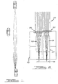
- the optical system includes a pair of lenses 103 and 104, a lens holder 105 and an image array sensor 106.
- the lenses 103 and 104 vertically spaced apart in order to allow imaging of the same field of view onto different portions of the array.
- the lenses 103, 104 image generally the same fields of view because the distance between the lenses 103, 104 is relatively small relative to the light sources within the field of view of the device.
- the lens 103 may be formed with a red filter dye for transmitting light with wavelengths greater than 600 nm and focusing red light rays 101 from tail lamps onto one half of the image array sensor 106.
- the red filter dye causes the lens 103 the absorb all light rays at the blue end of the visible spectrum and transmit light rays at the red end of the spectrum.
- the amount of light transmitted from non-red light sources, such as head lamps, is greatly reduced while light rays from tail lamps are fully transmitted through the lens 103.
- the relative brightness of the light rays from tail lamps imaged onto the image array sensor 106 is greatly increased.
- the lens 104 may be formed with a cyan filtered dye for transmitting light with wavelengths less than 600 nm.
- the lens 104 is used to focus the light rays onto the other half of the image array sensor 106.
- the cyan filter dye has a complementary effect to the red filter described above.
- the red filter dye transmits light from the blue end of the visible spectrum while absorbing light from the red end of the spectrum. As such, most of the light from sources, such as head lights, are transmitted through the lens 104 while virtually all of the light emanating from tail lamps is blocked.
- Both head lamps and tail lamps emit a substantial amount of infrared light.
- the infrared light transmitted by the head lamps and tail lamps will be substantially blocked by the lenses 103 and 104.
- the ratio between intensity between red lights imaged through the red filter and red light imaged through the cyan filter will be substantially increased.
- the use of the red and cyan dyes for the lenses 103 and 104 is merely exemplary.
- the filter characteristics of the lenses 103 and 104 are selected to optimize the sensitivity of the device to specific light sources. For example, if the head lamps or tail lamps in new vehicles may be replaced with alternative light sources with different spectral composition, for example, with high intensity discharge head lamps and light emitting diode tail lamps requiring different filter characteristics. Depending on the spectral characteristics of the head lamps and tail lamps, transparent lenses 103 and 104 may be utilized with separate color filters.
- the lenses 103 and 104 may be formed as acrylic spherical lenses. Alternatively, the lenses 103 and 104 may be formed as aspherical lens in order to minimize color dispersion and spherical aberration present with spherical lens. Complex lenses formed from both spherical and aspherical lenses are also contemplated.
- a single lens may also be used in place of the separate lenses 103 and 104.
- the use of a single lens may be used to image the field of view onto a full or partial color image array sensor containing pigmentation on the individual pixels in the array.
- the horizontal distance between the two lenses 103 and 104 and the image array sensor 106 is slightly different. Offsetting of the two lenses 103 and 104 compensates for the color dispersion created as a result of the fact that the index of refraction of materials varies with the wavelength of light transmitted through it. Because the two lenses 103 and 104 transmit different portions of the visible spectrum, the distance between the lenses 103 and 104 and the image array sensor, 106 is optimized to minimize the dispersion for the band of light transmitted by each of the lenses 103 and 104.
- the lens holder 105 is provided with cutouts 107 and preferably formed or coated with a light absorbing material. These cutouts 107 prevent light rays beyond the desired maximum vertical angle transmitted through the red lens 103 from being imaged onto the portion of the image array sensor 106 reserved for the light rays 102. Conversely, the cutouts 107 also prevent light rays transmitted through the lens 104 from being imaged onto the portion of the image array sensor 106 reserved for the light rays 101.
- the field of view of the optical system is defined by the configuration of the lenses 103 and 104 and the cutouts 107 relative to the image array sensor 106.
- an exemplary field of view of 10 degrees in the vertical direction and 20 degrees in the horizontal directions may be created by the configuration set forth below.
- the lenses 103 and 104 are selected with a diameter of 1.5 mm with a small portion cut away to allow the lenses 103 104 to be positioned such that their centers are separated by 1.0 mm.
- the lens 103 is positioned 4.15 mm from the image array sensor 106 while the lens 104 is positioned 4.05 mm away.
- Both the front and rear surface radii of the lenses 103 and 104 are 4.3 millimeters with a 0.2 millimeter thickness.
- circular cutouts 108 are formed in the lens holder 105.
- a pair of generally rectangular apertures 110 are formed in a rear wall 112.
- the rear apertures 110 are 1.6 millimeters in the horizontal direction and 0.8 millimeters in the vertical direction.
- the cutouts 107 taper from the rear apertures 110 to the diameter of the front cutouts 108 to provide the field of view discussed above.
- FIG. 3 illustrates how the system baffles light rays incident at angles beyond the vertical field of view.
- FIG. 4 illustrates light rays being imaged onto the image array sensor 106 within the horizontal field of view.
- the image array sensor 106 may be CMOS active pixel image sensor array for example, as disclosed in U.S. Patent No. 5,471,515, hereby incorporated by reference and available from Photobit LLC of La Crasenta, California. CMOS active pixel image sensors provide relatively high sensitivity and low power consumption as well as the ability the integrate other CMOS electronics on the same chip.
- the image array sensor 106 may be a 50 x 50 40 m pixel array. The number of pixels in the image array sensor 106 is selected such that not all pixels fall within the area that the lenses 103 and 104 project onto. The extra pixels allow for simple correction for mechanical misalignment by offsetting the expected image location.
- the image array sensor 106 provides spatial information regarding light sources within the field of view.
- the number of pixels present in the array is selected to obtain sufficient spatial detail although the size of the array is not limited and may be selected and may even be dictated by physical and economic limitations.
- the image array sensor 106 must be sensitive to accurately detect tail lights at several hundred feet. Such sensitivity may be achieved by lengthening the amount of time the photosites in the array are exposed to light during a frame period.
- a frame period is selected to enable the array to capture and transfer a frame to the image processing system in a short enough time to allow the image processing system to detect another vehicle entering the field of view.
- a short time period also limits the amount of motion within a frame during the integration period and thus produces a relatively more accurate instantaneous image.
- the use of a pixel array also provides other benefits.
- the light integration time to capture a frame can be varied.
- Such a feature allows the system to provide optimal results in varying degrees in darkness.
- Another important aspect of an image array sensor is the ability to utilize subsets of the pixels within the array or an individual pixel. As such, as the window size is decreased, the readout rates can be increased.
- Such a feature allows the system to discriminate ambient light sources, such as street lamps. In particular, such a feature allows the system to locate a light source within the frame and capture several samples of the light sources at a rate several times greater than 60 hz.
- the light source is likely a street lamp or other light source powered from a 60 Hz AC power supply. If the light source is not modulated, the light source is likely powered by the vehicle's DC power supply.
- the image array sensor allows the field of view immediately in front of the vehicle to imaged by a higher pixel resolution.
- the system may be configured such that the effective pixel resolution decreases as the angle of the vehicle relative to the control vehicle increases thus reducing the amount of processing time in those areas.
- Such a configuration reduces the sensitivity of the device to light sources from reflective stationary objects on the side of the road.
- An image array sensor could be manufactured in which the pixel pitch is varied as a function of the area in the field of view that the pixel images. For example, pixels imaging the space corresponding to horizontal angles within 3 degrees of the center of the vehicle may be provided with a 10 ⁇ m pixel pitch. Pixels imaging horizontal angles between 3 and 6 degrees may be provided with a 20 ⁇ m pixel pitch, while those imaging angles greater than 60 degrees may be provided with a 40 ⁇ m pitch. While such a configuration may not increase the sensing area, the ability the resolve detail increases; an important aspect in considering that relative size of a tail lamp at a relatively large distance. For example, a 4 inch diameter tail light at a distance of 200 feet subtends an angle of less than 0.11 degrees. If a 50 x 50 image array sensor is used to image a 20 degree field of view, the tail lamp would subtend approximately 8% of the total area imaged by the pixel.
- a tail lamp is relatively brighter than its ambient surroundings, however, the red light contributed by the tail light is diluted by the ambient light at such a distance. Such a factor is critical when comparing the amount the red light in a given area to the amount of non-red light in the same area. When the area of space compared is large relative to the light source, the percentage of red light is diminished. By comparison, if 10 ⁇ m pixels are used in the center of the array 106 instead of 40 ⁇ m pixels, the tail lamp would subtend 0.04% of the total areas, an improvement of 16 times.
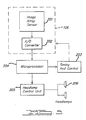
- the image processing is illustrated in FIGS. 5-8.
- the image processing system includes the image array sensor 106, a microprocessor 204, for example, a Motorola type HC08, a head lamp control unit 205 and a pair of head lamps 206.
- an active pixel array sensor may be utilized for the image array sensor 106.
- Such an active pixel array sensor includes an image array 201 and an analog to digital converter (ADC) 202.
- a timing and control circuit is used to control the image array 201 as well as the ADC 202 to control the integration time, read out timing, pixel selection, gain offset and other variables.
- the microprocessor 204 is used to analyze the data collected by the image array sensor 201.
- the microprocessor 204 is in communication with the head lamp control unit, a conventional unit, implemented, for example, as a relay, which, in turn, controls the head lamps 206.
- the head lamp control unit 205 in turn, changes the voltage applied to the head lamp 206 to cause the high beam or bright lamp to be switched on or off.
- the flow chart for the head lamp control is illustrated in FIG. 6.
- the system runs in a continuous cycle with occasional interrupts for absolute light measurements, adjustments of ADC parameters or other functions.
- step 302 the images from the lenses 103 and 104 are analyzed to detect tail lamps.
- Another image is acquired in step 303 through the lens 104.
- the image acquired through the lens 104 is acquired with a low enough gain to detect oncoming head lights while rejecting lower light level reflections and nuisance light sources.
- the system checks for very bright lights in the image indicating the sudden appearance of vehicle head lamps or tail lamps within the field of view, as is the case, when a car turns in front of the controlled vehicle in step 305. If bright lights are sensed, the device dims the head lamps 206 immediately and bypasses the time verification as discussed below. The cycle is then repeated. If there were no bright lights, the system proceeds to step 307 to determine if there are any head lamps or tail lamps in the image.
- an undim counter and a dim counter are used. These counters provide verification of a particular light source whether from a tail lamp or head lamp from consecutive frames before signaling the head lamp control unit 205 to dim or undim the head lamps 206, except as described above, when a bright light is detected. By providing verification, anomalies within the device or in the image will not cause spurious operation of the head lamps 206.
- the dim counter is incremented each time a frame with a head lamp or tail lamp is detected until the number of required consecutive frames to take action is reached.
- the dim counter is set to 0 each time a clear frame is processed.
- the undim counter is incremented with each clear frame and set to 0 with each frame containing a head lamp or tail lamp.
- the actual number of consecutive frames required to dim or undim is determined by the overall speed of the device. The more frames used for verification, the less susceptible the system will be to noise and anomalies. However, the device must be able to react quickly to be effective so the number of verification frames is kept relatively low. Whenever a head lamp or tail lamp is detected in step 307, the undim counter is set to 0 in step 308.
- step 309 the system checks whether the head lamp 206 high beams are on. If the high beams are off, no further action is required and the cycle is repeated as indicated by step 317. If the high beams are on, the dim counter is incremented in step 310. After the dim counter is incremented in step 310, the system checks in step 311, if the dim counter has reached the number of consecutive frames required to dim the head lamps 206. If so, the system proceeds to step 306 and dims the head lamps 206 and resets both the dim and undim counters and repeats the cycle. Otherwise, the system repeats the cycle and proceeds to step to 317.
- step 307 if there are no head lamps or tail lamps in the image, the dim counter is set to 0 in step 312. Subsequently, in step 313, the system determines whether the high beams 206 are on. If the high beams are on, the system exits repeats the cycle in step 317. In step 313 if the brights are not on, the undim counter is incremented. After the undim counter is incremented, the system checks in step 315 whether the undim counter has reached the number of consecutive clear frames required to activate the high beams 206. If so, the high beams are turned on in step 316, and the cycle is repeated. If the undim counter is less than the required number for activating the bright head lamps 206, the system repeats the cycle in step 317.
- the primary method of identifying an object involves comparing the gray scale value of a pixel through the lens 103 to a gray scale value of the pixel representing the same space imaged through the lens, 104. If the value of the pixel imaged through the lens 103 is significantly higher than the value of the pixel imaged through the lens 104, the light source is determined to be red light. In addition to determining if the light is red, the system also checks the brightness of the red light before deciding that the light is a tail lamp by determining if the gray scale value of the pixel is greater than a threshold value. As is known in the art, the brightness of a light source varies with the square of the distance of the light source from the observer. As such, an approximate determination of the distance of a leading vehicle can be made to determine the appropriate time to dim the head lamps.
- the threshold value may be computed in a variety of ways. For example, it can be a predetermined fixed number or a number that is a function of the current image sensor and ADC settings. The threshold value can also be determined by computing a threshold as a factor of the average pixel intensity of the entire image which would help eliminate variances caused by changing ambient light sources.
- the pixel value may be compared to the average of the pixels in the immediate area of the pixel of interest. This local average method prevents relatively large, moderately bright spots in the image from being seen as vehicle light sources. More particularly, distant tail lamps subtend less than one pixel and thus will only have moderate brightness. Large spots in the image with moderate brightness are most likely caused by reflections from large objects. Close tail lamps which subtend many pixels will have a saturated center which will be brighter than the surrounding pixels allowing the same method to detect them as well.
- the threshold may also be determined by varying the threshold spatially by way of a look up table or computation. However, the threshold should be determined so that dimming occurs appropriately for the dimmest tail lights allowed by the DOT standards. Distant vehicles are subjected to the most intense portion of the controlled vehicle high beam, thus requiring dimming only directly in front of the controlled vehicle as indicated in FIG. 1. Thus, a relatively low threshold may be selected for light sources imaged directly in front of the control vehicle while a higher threshold for light sources that are not directly in front of the control vehicle. For example, as discussed in connection with FIG.
- the threshold for pixels imaging the field of view 3 degrees, right and left of the center should correspond to a light level incident on the image array sensor 106 about 4 times as bright as the threshold for red light directly in front of the vehicle and 12 times as bright for vehicles at 6 degrees.
- Such a spatially varying threshold helps eliminate false tail lamp detection caused by red reflectors by making the system less sensitive to areas of to the sides of the control vehicle.
- a similar approach can be taken for varying the threshold for pixels in imaging areas of space and angles above and below the center.
- a more conservative approach can be taken when determining the tail light sensitivity relative to the vertical angle since vehicles tend to move more frequently and rapidly in vertical directions due to hills, and bumps in the road. Therefore by specifying relatively tight vertical thresholds may cause the bright head lamps 206 to switch on and off as the vehicle moves several degrees up and down.
- a hysteresis multiplier may be applied to the threshold to prevent oscillations of the head lamps 206 when the light source has a gray scale value at or near the threshold.
- the threshold will be lower for all pixels to prevent the bright head lamps from coming back on even if the faintest tail lamps are present in the image.
- the threshold should be higher so that only tail lamps of sufficient brightness are sensed to indicate that the car is within the dimming range to cause the head lamps 206 to dim.
- the speed at which the control vehicle overtakes a stationary object is much greater than the relative rate a vehicle would overtake another moving vehicle.
- the rate of increase in brightness of the object would be typically much greater for a stationary reflector than for another vehicle.
- This rate of change in brightness coupled with rightward horizontal motion can be used as signatures to reduce the number of false tail lamps detected.
- a computationally simpler method of analyzing spatial motion of a light source is to simply take several consecutive regions of the local region of interest where the light source is located. Motion in the vertical and horizontal directions is relatively slow for tail lamps of a leading vehicle. Simply sampling a pixel a few consecutive times to see if the tail lamp is present in all samples can adequately eliminate objects which rapidly move within the image.
- step 318 the system ascertains if the pixel is within the tail lamp window.
- red lights are imaged onto half of the image array sensor 106.
- step 319 the system proceeds to step 319 and moves to another pixel.
- the first criteria relates to comparing the gray scale value of the pixel image through the lens 103 with a corresponding gray scale value for the same area in space imaged through the lens 104.
- the gray scale value of the pixel imaged through the lens 103 is significantly larger than the gray scale value of the corresponding pixel imaged through the lens 104, one of the criteria for detecting a tail lamp, is met.
- the gray scale value of the pixel imaged through the lens 103 is compared with the gray scale value of a corresponding pixel imaged through the lens 104 in step 320. If the gray scale value of the pixel image through the lens 103 is not n% greater than the corresponding pixel imaged by the lens 104 the system proceeds to step 319 and examines another pixel. Otherwise, the system proceeds to step 321 and calculates the threshold for the particular pixel based on the region of space it images. For example, as discussed above, the pixel thresholds may be varied based on their spatial relationship within the image array sensor.
- the system calculates the average gray scale value of neighboring pixels. If it is determined in step 323 that the pixel gray scale value for the pixel imaged through the lens 103 is n% greater than the average gray scale value of the neighboring pixels, the system proceeds to step 324 and adds the pixel to the tail lamp list for future frames of reference. Otherwise, the system moves to step 319 and moves the next pixel. In steps 325 and 326, the systems determines whether or not the red light detected is a tail lamp or a reflector, as discussed above. If it is determined that the light is a reflector, the system proceeds to step 327 and moves on to the next pixel. Otherwise, the head lamps are dimmed in step 328.
- Head lamp detection is similar to tail lamp detection.
- the primary difference is that only the lens 104 is utilized.
- the pixel integration time is shorter and the ADC parameters are such that the image only shows very bright objects, such as head lamps. Most reflections have low intensity light sources fall well below the zero threshold of the ADC.
- pixels are compared to the local average intensity of the neighboring pixels. Spatial variances in the thresholds may be set so that pixels corresponding to the center of the field of view are more sensitive pixels to the left of the- image (left hand drive countries) have higher thresholds. These thresholds, however, should not vary spatially to the same degree as the threshold for the tail lamps because of the relatively wide variance in the emission patterns observed from head lamps.
- the head lamps may be controlled and dimmed relatively more rapidly than in the case when a tail lamp from a vehicle traveling in the same direction is detected. Similar to the tail lamp processing circuit hysteresis may be added to prevent cycling of the head lamps.
- head lamp detection arises from the rapid decrease in distance between oncoming vehicles which becomes especially critical when an oncoming vehicle suddenly enters the controlled vehicle's field of view, for example, when turning a comer or in a similar situation. For this reason, additional flag is used to cause the vehicle to immediately dim the bright head lamps and bypass any verification if the light source is above certain absolute high level brightness threshold.
- the primary nuisance light source complicating head lamp detection comes from overhead lights, such as street lights and electrically illuminated street signs.
- One method of eliminating such nuisance light sources is to analyze their motion. In particular, all overhead street lamps will move vertically upwards in the image as the controlled vehicle is moving. Analyzing this motion provides an efficient method of detecting some street lamps. Unfortunately, distant street lamps appear to be at almost the same elevational angles as distant head lights and the rate of vertical climb in the image does not become great until the street lamp is closer. However, as discussed above, street lighting is AC controlled and thus is subject to 120 Hz intensity modulation. Head lamps powered by DC source do not exhibit this characteristic. Thus, the image array sensor 106 is able to utilize small number of pixels that for taking several rapid consecutive readings in a window.
- the window can read several hundred frames per second. Once the light source is identified in the image, several frames are read out at a rate of 240 Hz or higher. These readings are then analyzed to detect the intensity modulation. If modulation is present, the light source originates from an AC source and can be ignored. Alternatively, a photodiode can used in conjunction with a low pass filter to determine the ratio of light in the image that was AC modulated to the unmodulated light. If a significant portion of the light source is AC modulated, the light source present in the image is assumed to be from AC light. Otherwise, the light source is assumed to be from a DC source.
- step 329 determines in step 329 whether the pixel is in the head lamp window (i.e. that portion the image array sensor 106 reserved for light arrays imaged through the lens 104). If not, the system proceeds to step 330 and examines the next pixel. Otherwise, the system examines the pixel in step 331 to determine if the pixel is modulated at 120 Hz as discussed above. If so, the light source is assumed to be a street lamp and thus, the system proceeds to the next pixel in step 330. If the pixel is not subject to 120 Hz intensity modulation, the system then computes the average gray scale of neighboring pixels in step 332.
- step 333 the system determines the threshold for the particular pixel based on the area of the space it images.
- the system next compares the gray scale value of the pixel with an absolute high level threshold in step 334, for example, to determine if any oncoming cars suddenly come into the field of view of the controlled vehicle. If so, the system proceeds to step 335 and sets a flag to cause immediate dimming. Otherwise, the system proceeds to step 336 and determines if the gray scale value of the pixel is n% greater than the average of neighboring pixels. If not, the system returns to step 330 and examines the next pixel. Otherwise, the system proceeds to step 337 and adds the pixel to the head lamp list for future frames to reference.
- the system examines light sources as discussed above in steps 338 and 339 to determine if the light source is a street lamp. If the system determines that the light source is not a street lamp, the system proceeds to step 340 and sets a flag to cause dimming of the head lamps 206. If the system determines that the light source is a street lamp, the system proceeds to step 341 and moves on to the next pixel.
- Traditional vehicle lamps systems have the option of the bright lamps being either on or off.
- the present invention is readily adaptable for use with a head lamp system where the brights can be activated to a varying the brightness based on the distance of other vehicles in the field of view. In such an embodiment, the brightness of the head lamps may be varied by various techniques including modulating the duty cycle of the head lamp in order to reduce or increase the overall brightness level.
- Variable intensity head lamps also result in better noise filtration.
- a light source which causes the brightness of the controlled head lamps of the vehicles to be decreased
- other images can be detected to determine if the intensity of these other light sources decreases by a similar amount. If so, the system would be able to determine that the light source is a reflection from the vehicle's head lamps.
- Such information can be used as feedback to provide a relatively efficient means for eliminating nuisance light caused by reflections of the control vehicle head lamps.
- the brightness threshold discussed above would not be used. More particularly, the brightness of the brightest head lamp and tail lamp in the images is used to determine the brightness of the controlled vehicle's head lamps. The brighter the head lamps or tail lamp in the images, the dimmer the controlled head lamps.
Abstract
Description
- The present invention relates to a system for automatically dimming vehicle high beam head lamps and more particularly to a system which includes an improved optical system and an image processing system, the optical system being adapted to discriminate both the horizontal and vertical position of light rays within a predetermined field of view and spatially segregate the light rays on a pixel sensor array in order to provide improved discrimination of vehicle head lamps and vehicle tail lamps relative to other ambient light sources. The image processing system provides further discrimination of ambient light sources in order to automatically dim vehicle head lamp high beams as a function of the angular position of another vehicle relative to the control vehicle.
- Regulations set forth by the United States Department of Transportation (DOT) regulate the light emissions of vehicle high beam head lamps. Various state regulations are used to control the amount of glare experienced by drivers of other vehicles whether the vehicle is traveling in the same direction as the controlled vehicle or in an opposite direction.
- Known vehicle high beam head lamp emissions in accordance with the DOT regulations provide an intensity of 40,000 cd at 0 degrees, 10,000 cd at 3 degrees, 3250 cd at 6 degrees, 1500 cd at 9 degrees and 750 cd at 12 degrees. An example of such an emission pattern is illustrated in FIG. 1. In order to avoid an illuminance of 0.5 foot candles (fc) incident on another vehicle, the vehicle high beam head lamps should be dimmed within 230 feet of another vehicle at 0 degrees, 115 feet of another vehicle at a horizontal position of 3 degrees relative to the datum, and 65 feet in the position of the other vehicle is 6 degrees relative to the controlled vehicle.
- Various known head light dimmer control systems are known in the art. In order to prevent the drivers of other vehicles from being subjected to excessive glare levels, such automatic head lamp dimmer systems must sense both the head lights as well as the tail lights of other vehicles. While many known systems are adequately able to detect head lamps of oncoming vehicles, such systems are known to inadequately sense tail lights of vehicles traveling ahead of the control vehicle. As such, such systems are not able to automatically dim the high beam head lamps in time to prevent drivers of the vehicles traveling in the same direction as the controlled vehicle being subjected to excessive glare levels.
- U.S. Patent No. 5,537,003 assigned to the same assignee of the present invention discloses an automatic head lamp dimming system which includes an optical system for sensing tail lamps as well as head lamps. The '003 patent discloses a single photo diode with a mechanical scanning arrangement for scanning a predetermined field of view. Although the system provides relatively suitable sensing of head lamps as well as tail lamps, the optical subsystem is rather complicated and expensive to manufacture.
- It is an object of the present invention to solve various problems in the prior art.
- It is yet another object of the present invention to provide a vehicle head lamp dimming system which eliminates the need for mechanical optical scanning systems.
- It is yet another object of the present invention to provide a head lamp dimming system that is adapted to dim the high beam head lights at different distances as a function of the horizontal angular position of another vehicle relative to the controlled vehicle.
- Briefly, the present invention relates to an automatic vehicle head lamp dimming system. The system includes an optical system and an imaging processing system. The optical system is configured to discriminate between head lamps and tail lamps and focus the light rays from the head lamps and tail lamps on different portions of a pixel sensor array. The optical system as well as the image processing system provides for relatively increased discrimination of head lamps and tail lamps of other vehicles and also enables the high beam head lamps of the control vehicle to be controlled as a function of the distance as well as horizontal angular position of other vehicles relative to the controlled vehicle.
- These and other objects of the present invention will be readily understood with reference to the following specification and attached drawing, wherein:
- FIG. 1 is a top view illustrating the head lamp emission pattern of a conventional high beam head lamp.
- FIG. 2 is a side cross sectional view of the optical system which forms a part of the present invention illustrating light rays incident at a vertical angle within the desired field of view.
- FIG. 3 is similar to FIG. 2 illustrating the light rays incident at a vertical elevation angle beyond the desired field of view.
- FIG. 4 is a top cross sectional view of the optical system illustrated in FIG. 1 illustrating the light rays at a horizontal angle within the desired field of view.
- FIG. 5 is a block diagram of the automatic head light dimming system in accordance with the present invention.
- FIG. 6 is an overall flow diagram of the image processing in accordance with the present invention.
- FIG. 7 is a flow diagram illustrating the method for detecting tail lamps of vehicles within the desired field of view.
- FIG. 8 is a flow diagram for detecting head lamps from other vehicles within the desired field of view.
-
- The automatic head lamp dimming system in accordance with the present invention includes an optical system as illustrated in FIGS. 2-4 and an image processing system as illustrated in FIGS. 5-8. In order to enable the high beam head lamps to remain on for the longest reasonable time without the subjecting the driver of another vehicle to excessive glare, the automatic head lamp dimming system in accordance with the present invention controls the vehicle high beam head lamps as a function of the distance as well as the horizontal angular position of the other vehicle relative to the controlled vehicle. As will be discussed in more detail below, the optical system is adapted to discriminate between head lamps and tail lamps of other vehicles. The light rays from the head lamps and tail lamps of other vehicles are spatially segregated on a pixel sensor array to provide increased discrimination of head lamps and tail lamps relative to other ambient light sources, such as road signs and reflections from snow and the like. The optical system enables both the horizontal and vertical position of incident lights sources to be determined within the field of view of the optical system. The image processing system processes the pixels to provide for automatic control of the head lamps as a function of the distance and horizontal angular position of another vehicle relative to the control vehicle. As such, the system in accordance with the present invention is adapted to provide optimal control of the vehicle high beam head lamps by allowing the high beam head lamps to remain on for as long as possible while preventing the driver of the other vehicle from being subjected to an undue amount of glare.
- Referring to FIGS. 2-4, the optical system includes a pair of
lenses lens holder 105 and animage array sensor 106. As best shown in FIGS. 2 and 3, thelenses lenses lenses - The
lens 103 may be formed with a red filter dye for transmitting light with wavelengths greater than 600 nm and focusingred light rays 101 from tail lamps onto one half of theimage array sensor 106. The red filter dye causes thelens 103 the absorb all light rays at the blue end of the visible spectrum and transmit light rays at the red end of the spectrum. As such, the amount of light transmitted from non-red light sources, such as head lamps, is greatly reduced while light rays from tail lamps are fully transmitted through thelens 103. As such, the relative brightness of the light rays from tail lamps imaged onto theimage array sensor 106 is greatly increased. - The
lens 104 may be formed with a cyan filtered dye for transmitting light with wavelengths less than 600 nm. Thelens 104 is used to focus the light rays onto the other half of theimage array sensor 106. The cyan filter dye has a complementary effect to the red filter described above. In particular, the red filter dye transmits light from the blue end of the visible spectrum while absorbing light from the red end of the spectrum. As such, most of the light from sources, such as head lights, are transmitted through thelens 104 while virtually all of the light emanating from tail lamps is blocked. - Both head lamps and tail lamps emit a substantial amount of infrared light. By utilizing lenses with a filter dye or separate filters which inhibit light at wavelengths greater about 750 nm, the infrared light transmitted by the head lamps and tail lamps will be substantially blocked by the
lenses - The use of the red and cyan dyes for the
lenses lenses transparent lenses - The
lenses lenses - A single lens may also be used in place of the
separate lenses - As shown best in FIGS. 2 and 3, the horizontal distance between the two
lenses image array sensor 106 is slightly different. Offsetting of the twolenses lenses lenses lenses - As mentioned above, the light rays 101 transmitted through the
lens 103 are imaged onto one-half of theimage array sensor 106 while the light rays 102 transmitted through thelens 104 are imaged onto the other half of theimage array sensor 106. In order to provide such spatial segregation of the light rays transmitted through thelenses lens holder 105 is provided withcutouts 107 and preferably formed or coated with a light absorbing material. Thesecutouts 107 prevent light rays beyond the desired maximum vertical angle transmitted through thered lens 103 from being imaged onto the portion of theimage array sensor 106 reserved for the light rays 102. Conversely, thecutouts 107 also prevent light rays transmitted through thelens 104 from being imaged onto the portion of theimage array sensor 106 reserved for the light rays 101. - The field of view of the optical system is defined by the configuration of the
lenses cutouts 107 relative to theimage array sensor 106. For example, an exemplary field of view of 10 degrees in the vertical direction and 20 degrees in the horizontal directions may be created by the configuration set forth below. In particular, for such a field of view, thelenses lenses 103 104 to be positioned such that their centers are separated by 1.0 mm. Thelens 103 is positioned 4.15 mm from theimage array sensor 106 while thelens 104 is positioned 4.05 mm away. Both the front and rear surface radii of thelenses - As best shown in FIGS. 3 and 4,
circular cutouts 108 are formed in thelens holder 105. A pair of generallyrectangular apertures 110 are formed in arear wall 112. Therear apertures 110 are 1.6 millimeters in the horizontal direction and 0.8 millimeters in the vertical direction. As best shown, in FIG.4, thecutouts 107 taper from therear apertures 110 to the diameter of thefront cutouts 108 to provide the field of view discussed above. - The configuration described above is thus able to baffle light outside of the desired horizontal and vertical field of view. In particular, FIG. 3 illustrates how the system baffles light rays incident at angles beyond the vertical field of view. FIG. 4 illustrates light rays being imaged onto the
image array sensor 106 within the horizontal field of view. - The
image array sensor 106 may be CMOS active pixel image sensor array for example, as disclosed in U.S. Patent No. 5,471,515, hereby incorporated by reference and available from Photobit LLC of La Crasenta, California. CMOS active pixel image sensors provide relatively high sensitivity and low power consumption as well as the ability the integrate other CMOS electronics on the same chip. Theimage array sensor 106 may be a 50 x 50 40 m pixel array. The number of pixels in theimage array sensor 106 is selected such that not all pixels fall within the area that thelenses - The
image array sensor 106 provides spatial information regarding light sources within the field of view. The number of pixels present in the array is selected to obtain sufficient spatial detail although the size of the array is not limited and may be selected and may even be dictated by physical and economic limitations. Theimage array sensor 106 must be sensitive to accurately detect tail lights at several hundred feet. Such sensitivity may be achieved by lengthening the amount of time the photosites in the array are exposed to light during a frame period. A frame period is selected to enable the array to capture and transfer a frame to the image processing system in a short enough time to allow the image processing system to detect another vehicle entering the field of view. A short time period also limits the amount of motion within a frame during the integration period and thus produces a relatively more accurate instantaneous image. - The use of a pixel array also provides other benefits. For example, as mentioned above, the light integration time to capture a frame can be varied. Such a feature, allows the system to provide optimal results in varying degrees in darkness. Another important aspect of an image array sensor is the ability to utilize subsets of the pixels within the array or an individual pixel. As such, as the window size is decreased, the readout rates can be increased. Such a feature allows the system to discriminate ambient light sources, such as street lamps. In particular, such a feature allows the system to locate a light source within the frame and capture several samples of the light sources at a rate several times greater than 60 hz. In particular, if the samples exhibits 120 Hz intensity modulation, the light source is likely a street lamp or other light source powered from a 60 Hz AC power supply. If the light source is not modulated, the light source is likely powered by the vehicle's DC power supply.
- Another potential benefit of the image array sensor is that it allows the field of view immediately in front of the vehicle to imaged by a higher pixel resolution. Thus, the system may be configured such that the effective pixel resolution decreases as the angle of the vehicle relative to the control vehicle increases thus reducing the amount of processing time in those areas. Such a configuration reduces the sensitivity of the device to light sources from reflective stationary objects on the side of the road.
- An image array sensor could be manufactured in which the pixel pitch is varied as a function of the area in the field of view that the pixel images. For example, pixels imaging the space corresponding to horizontal angles within 3 degrees of the center of the vehicle may be provided with a 10 µm pixel pitch. Pixels imaging horizontal angles between 3 and 6 degrees may be provided with a 20 µm pixel pitch, while those imaging angles greater than 60 degrees may be provided with a 40 µm pitch. While such a configuration may not increase the sensing area, the ability the resolve detail increases; an important aspect in considering that relative size of a tail lamp at a relatively large distance. For example, a 4 inch diameter tail light at a distance of 200 feet subtends an angle of less than 0.11 degrees. If a 50 x 50 image array sensor is used to image a 20 degree field of view, the tail lamp would subtend approximately 8% of the total area imaged by the pixel.
- A tail lamp is relatively brighter than its ambient surroundings, however, the red light contributed by the tail light is diluted by the ambient light at such a distance. Such a factor is critical when comparing the amount the red light in a given area to the amount of non-red light in the same area. When the area of space compared is large relative to the light source, the percentage of red light is diminished. By comparison, if 10 µm pixels are used in the center of the
array 106 instead of 40 µm pixels, the tail lamp would subtend 0.04% of the total areas, an improvement of 16 times. - The image processing is illustrated in FIGS. 5-8. The image processing system includes the
image array sensor 106, amicroprocessor 204, for example, a Motorola type HC08, a headlamp control unit 205 and a pair ofhead lamps 206. As mentioned above, an active pixel array sensor may be utilized for theimage array sensor 106. Such an active pixel array sensor includes animage array 201 and an analog to digital converter (ADC) 202. A timing and control circuit is used to control theimage array 201 as well as theADC 202 to control the integration time, read out timing, pixel selection, gain offset and other variables. Themicroprocessor 204 is used to analyze the data collected by theimage array sensor 201. Themicroprocessor 204 is in communication with the head lamp control unit, a conventional unit, implemented, for example, as a relay, which, in turn, controls thehead lamps 206. The headlamp control unit 205 in turn, changes the voltage applied to thehead lamp 206 to cause the high beam or bright lamp to be switched on or off. - The flow chart for the head lamp control is illustrated in FIG. 6. The system runs in a continuous cycle with occasional interrupts for absolute light measurements, adjustments of ADC parameters or other functions.
- At the beginning of each cycle, two images are acquired through the
lenses step 302, the images from thelenses lens 104. The image acquired through thelens 104 is acquired with a low enough gain to detect oncoming head lights while rejecting lower light level reflections and nuisance light sources. After the images are analyzed, the system checks for very bright lights in the image indicating the sudden appearance of vehicle head lamps or tail lamps within the field of view, as is the case, when a car turns in front of the controlled vehicle instep 305. If bright lights are sensed, the device dims thehead lamps 206 immediately and bypasses the time verification as discussed below. The cycle is then repeated. If there were no bright lights, the system proceeds to step 307 to determine if there are any head lamps or tail lamps in the image. - In order to confirm the presence or lack of presence of a head lamp or tail lamp in a frame, an undim counter and a dim counter are used. These counters provide verification of a particular light source whether from a tail lamp or head lamp from consecutive frames before signaling the head
lamp control unit 205 to dim or undim thehead lamps 206, except as described above, when a bright light is detected. By providing verification, anomalies within the device or in the image will not cause spurious operation of thehead lamps 206. - The dim counter is incremented each time a frame with a head lamp or tail lamp is detected until the number of required consecutive frames to take action is reached. The dim counter is set to 0 each time a clear frame is processed. The undim counter is incremented with each clear frame and set to 0 with each frame containing a head lamp or tail lamp. The actual number of consecutive frames required to dim or undim is determined by the overall speed of the device. The more frames used for verification, the less susceptible the system will be to noise and anomalies. However, the device must be able to react quickly to be effective so the number of verification frames is kept relatively low. Whenever a head lamp or tail lamp is detected in
step 307, the undim counter is set to 0 instep 308. Instep 309, the system checks whether thehead lamp 206 high beams are on. If the high beams are off, no further action is required and the cycle is repeated as indicated bystep 317. If the high beams are on, the dim counter is incremented instep 310. After the dim counter is incremented instep 310, the system checks instep 311, if the dim counter has reached the number of consecutive frames required to dim thehead lamps 206. If so, the system proceeds to step 306 and dims thehead lamps 206 and resets both the dim and undim counters and repeats the cycle. Otherwise, the system repeats the cycle and proceeds to step to 317. - In
step 307, if there are no head lamps or tail lamps in the image, the dim counter is set to 0 instep 312. Subsequently, instep 313, the system determines whether thehigh beams 206 are on. If the high beams are on, the system exits repeats the cycle instep 317. Instep 313 if the brights are not on, the undim counter is incremented. After the undim counter is incremented, the system checks instep 315 whether the undim counter has reached the number of consecutive clear frames required to activate thehigh beams 206. If so, the high beams are turned on instep 316, and the cycle is repeated. If the undim counter is less than the required number for activating thebright head lamps 206, the system repeats the cycle instep 317. - The flow diagram for tail light processing is illustrated in FIG. 7. As will be discussed in more detail below, the primary method of identifying an object such as a tail light, involves comparing the gray scale value of a pixel through the
lens 103 to a gray scale value of the pixel representing the same space imaged through the lens, 104. If the value of the pixel imaged through thelens 103 is significantly higher than the value of the pixel imaged through thelens 104, the light source is determined to be red light. In addition to determining if the light is red, the system also checks the brightness of the red light before deciding that the light is a tail lamp by determining if the gray scale value of the pixel is greater than a threshold value. As is known in the art, the brightness of a light source varies with the square of the distance of the light source from the observer. As such, an approximate determination of the distance of a leading vehicle can be made to determine the appropriate time to dim the head lamps. - The threshold value may be computed in a variety of ways. For example, it can be a predetermined fixed number or a number that is a function of the current image sensor and ADC settings. The threshold value can also be determined by computing a threshold as a factor of the average pixel intensity of the entire image which would help eliminate variances caused by changing ambient light sources. In addition, the pixel value may be compared to the average of the pixels in the immediate area of the pixel of interest. This local average method prevents relatively large, moderately bright spots in the image from being seen as vehicle light sources. More particularly, distant tail lamps subtend less than one pixel and thus will only have moderate brightness. Large spots in the image with moderate brightness are most likely caused by reflections from large objects. Close tail lamps which subtend many pixels will have a saturated center which will be brighter than the surrounding pixels allowing the same method to detect them as well.
- The threshold may also be determined by varying the threshold spatially by way of a look up table or computation. However, the threshold should be determined so that dimming occurs appropriately for the dimmest tail lights allowed by the DOT standards. Distant vehicles are subjected to the most intense portion of the controlled vehicle high beam, thus requiring dimming only directly in front of the controlled vehicle as indicated in FIG. 1. Thus, a relatively low threshold may be selected for light sources imaged directly in front of the control vehicle while a higher threshold for light sources that are not directly in front of the control vehicle. For example, as discussed in connection with FIG. 1, the threshold for pixels imaging the field of
view 3 degrees, right and left of the center should correspond to a light level incident on theimage array sensor 106 about 4 times as bright as the threshold for red light directly in front of the vehicle and 12 times as bright for vehicles at 6 degrees. Such a spatially varying threshold helps eliminate false tail lamp detection caused by red reflectors by making the system less sensitive to areas of to the sides of the control vehicle. - A similar approach can be taken for varying the threshold for pixels in imaging areas of space and angles above and below the center. However, a more conservative approach can be taken when determining the tail light sensitivity relative to the vertical angle since vehicles tend to move more frequently and rapidly in vertical directions due to hills, and bumps in the road. Therefore by specifying relatively tight vertical thresholds may cause the
bright head lamps 206 to switch on and off as the vehicle moves several degrees up and down. - A hysteresis multiplier may be applied to the threshold to prevent oscillations of the
head lamps 206 when the light source has a gray scale value at or near the threshold. Thus, if thebright head lamps 206 are off, the threshold will be lower for all pixels to prevent the bright head lamps from coming back on even if the faintest tail lamps are present in the image. However, if thebright head lamps 206 are on, the threshold should be higher so that only tail lamps of sufficient brightness are sensed to indicate that the car is within the dimming range to cause thehead lamps 206 to dim. - One of the biggest problems facing the detection of the tail lamps is the nuisance red light reflected from comer cube reflectors commonly found as markers on the side of the road and on mail boxes. The variable threshold method mentioned above helps eliminate some of this noise. However, when a vehicle approaches a reflector at the proper angles, it is relatively impossible to distinguish a red reflector from a tail lamp. Fortunately, by examining successive frames and investigating the motion of these objects over time, such reflections can be filtered. By storing the location of the tail lamps and images over time or by sensing small region of interest where the tail lamp is located, several consecutive times, the device can look for rightward motion and determine if the light source is a reflector. Additionally, the speed at which the control vehicle overtakes a stationary object is much greater than the relative rate a vehicle would overtake another moving vehicle. Thus, the rate of increase in brightness of the object would be typically much greater for a stationary reflector than for another vehicle. This rate of change in brightness coupled with rightward horizontal motion can be used as signatures to reduce the number of false tail lamps detected.
- A computationally simpler method of analyzing spatial motion of a light source is to simply take several consecutive regions of the local region of interest where the light source is located. Motion in the vertical and horizontal directions is relatively slow for tail lamps of a leading vehicle. Simply sampling a pixel a few consecutive times to see if the tail lamp is present in all samples can adequately eliminate objects which rapidly move within the image.
- The flow diagram for tail lamp processing is illustrated in FIG. 7. Initially, in
step 318, the system ascertains if the pixel is within the tail lamp window. In particular, as mentioned above, red lights are imaged onto half of theimage array sensor 106. Thus, if the pixel is not within the appropriate half of theimage array sensor 106, the system proceeds to step 319 and moves to another pixel. As mentioned above, there are two criteria for ascertaining whether the image is a tail lamp. The first criteria relates to comparing the gray scale value of the pixel image through thelens 103 with a corresponding gray scale value for the same area in space imaged through thelens 104. If the gray scale value of the pixel imaged through thelens 103 is significantly larger than the gray scale value of the corresponding pixel imaged through thelens 104, one of the criteria for detecting a tail lamp, is met. Thus, if the pixel of interest is within the lamp window as ascertained instep 318, the gray scale value of the pixel imaged through thelens 103 is compared with the gray scale value of a corresponding pixel imaged through thelens 104 instep 320. If the gray scale value of the pixel image through thelens 103 is not n% greater than the corresponding pixel imaged by thelens 104 the system proceeds to step 319 and examines another pixel. Otherwise, the system proceeds to step 321 and calculates the threshold for the particular pixel based on the region of space it images. For example, as discussed above, the pixel thresholds may be varied based on their spatial relationship within the image array sensor. - As discussed above, the other criteria for tail lamp detection relates to the relative brightness of the pixel relative to the neighbor pixels. Thus, in
step 322, the system calculates the average gray scale value of neighboring pixels. If it is determined instep 323 that the pixel gray scale value for the pixel imaged through thelens 103 is n% greater than the average gray scale value of the neighboring pixels, the system proceeds to step 324 and adds the pixel to the tail lamp list for future frames of reference. Otherwise, the system moves to step 319 and moves the next pixel. Insteps step 328. - The flow diagram for head light processing is illustrated in FIG. 8. Head lamp detection is similar to tail lamp detection. The primary difference is that only the
lens 104 is utilized. As mentioned above, the pixel integration time is shorter and the ADC parameters are such that the image only shows very bright objects, such as head lamps. Most reflections have low intensity light sources fall well below the zero threshold of the ADC. As such, pixels are compared to the local average intensity of the neighboring pixels. Spatial variances in the thresholds may be set so that pixels corresponding to the center of the field of view are more sensitive pixels to the left of the- image (left hand drive countries) have higher thresholds. These thresholds, however, should not vary spatially to the same degree as the threshold for the tail lamps because of the relatively wide variance in the emission patterns observed from head lamps. In addition, due to the relatively higher potential for more glare to the driver of an oncoming car, the head lamps may be controlled and dimmed relatively more rapidly than in the case when a tail lamp from a vehicle traveling in the same direction is detected. Similar to the tail lamp processing circuit hysteresis may be added to prevent cycling of the head lamps. - An additional concern with head lamp detection arises from the rapid decrease in distance between oncoming vehicles which becomes especially critical when an oncoming vehicle suddenly enters the controlled vehicle's field of view, for example, when turning a comer or in a similar situation. For this reason, additional flag is used to cause the vehicle to immediately dim the bright head lamps and bypass any verification if the light source is above certain absolute high level brightness threshold.
- The primary nuisance light source complicating head lamp detection comes from overhead lights, such as street lights and electrically illuminated street signs. One method of eliminating such nuisance light sources is to analyze their motion. In particular, all overhead street lamps will move vertically upwards in the image as the controlled vehicle is moving. Analyzing this motion provides an efficient method of detecting some street lamps. Unfortunately, distant street lamps appear to be at almost the same elevational angles as distant head lights and the rate of vertical climb in the image does not become great until the street lamp is closer. However, as discussed above, street lighting is AC controlled and thus is subject to 120 Hz intensity modulation. Head lamps powered by DC source do not exhibit this characteristic. Thus, the
image array sensor 106 is able to utilize small number of pixels that for taking several rapid consecutive readings in a window. If the window is small enough, the window can read several hundred frames per second. Once the light source is identified in the image, several frames are read out at a rate of 240 Hz or higher. These readings are then analyzed to detect the intensity modulation. If modulation is present, the light source originates from an AC source and can be ignored. Alternatively, a photodiode can used in conjunction with a low pass filter to determine the ratio of light in the image that was AC modulated to the unmodulated light. If a significant portion of the light source is AC modulated, the light source present in the image is assumed to be from AC light. Otherwise, the light source is assumed to be from a DC source. - The flow diagram for head lamp processing is illustrated in FIG. 8. Initially, the system determines in
step 329 whether the pixel is in the head lamp window (i.e. that portion theimage array sensor 106 reserved for light arrays imaged through the lens 104). If not, the system proceeds to step 330 and examines the next pixel. Otherwise, the system examines the pixel instep 331 to determine if the pixel is modulated at 120 Hz as discussed above. If so, the light source is assumed to be a street lamp and thus, the system proceeds to the next pixel instep 330. If the pixel is not subject to 120 Hz intensity modulation, the system then computes the average gray scale of neighboring pixels instep 332. Instep 333, the system determines the threshold for the particular pixel based on the area of the space it images. The system, next compares the gray scale value of the pixel with an absolute high level threshold instep 334, for example, to determine if any oncoming cars suddenly come into the field of view of the controlled vehicle. If so, the system proceeds to step 335 and sets a flag to cause immediate dimming. Otherwise, the system proceeds to step 336 and determines if the gray scale value of the pixel is n% greater than the average of neighboring pixels. If not, the system returns to step 330 and examines the next pixel. Otherwise, the system proceeds to step 337 and adds the pixel to the head lamp list for future frames to reference. - As discussed above, the system examines light sources as discussed above in
steps head lamps 206. If the system determines that the light source is a street lamp, the system proceeds to step 341 and moves on to the next pixel. Traditional vehicle lamps systems have the option of the bright lamps being either on or off. The present invention is readily adaptable for use with a head lamp system where the brights can be activated to a varying the brightness based on the distance of other vehicles in the field of view. In such an embodiment, the brightness of the head lamps may be varied by various techniques including modulating the duty cycle of the head lamp in order to reduce or increase the overall brightness level. - Variable intensity head lamps also result in better noise filtration. In particular, whenever a light source is detected which causes the brightness of the controlled head lamps of the vehicles to be decreased other images can be detected to determine if the intensity of these other light sources decreases by a similar amount. If so, the system would be able to determine that the light source is a reflection from the vehicle's head lamps. Such information can be used as feedback to provide a relatively efficient means for eliminating nuisance light caused by reflections of the control vehicle head lamps. In such an embodiment, the brightness threshold discussed above, would not be used. More particularly, the brightness of the brightest head lamp and tail lamp in the images is used to determine the brightness of the controlled vehicle's head lamps. The brighter the head lamps or tail lamp in the images, the dimmer the controlled head lamps.
- Obviously, many modifications and variations of the present invention are possible in light of the above teachings. Thus, it is to be understood that, within the scope of the appended claims, the invention may be practiced otherwise than as specifically described above.
Claims (42)
- A control system to control the brightness of the headlamps of a vehicle comprising:an image array sensor configurable to have variable sensitivities;an optical system configured to image the scene forward of the vehicle onto said image array sensor; anda processing system for processing images received from said image array sensor and for determining the sensitivity of said image array sensor, wherein a first sensitivity is selected when the high beams are substantially on and a second, different, sensitivity is selected when the high beams are substantially off.
- The control system of claim 1, wherein the first sensitivity is less than the second sensitivity.
- The control system of claim 1, wherein the output of said image sensor array is digitized by an analog to digital converter and the sensitivity of said image array sensor is varied by adjusting the parameters of said analog to digital converter.
- The control system of claim 3, wherein said analog to digital converter is contained in the same semiconductor device as said image array sensor.
- The control system of claim 1, wherein the integration of said image array sensor is variable, and the sensitivity of said image array sensor is varied by varying the integration time.
- The control system of claim 1, wherein the sensitivity of said image array sensor is varied by changing the gain of said image array sensor.
- A control system to control the brightness of the headlamps of a vehicle comprising:an image array sensor;an optical system configured to image the scene forward of the vehicle onto said image array sensor; anda processing system for:processing images received from said image array sensor,identifying light sources in said images,determining the brightness of said light sources within said images, andcomparing the brightness of light sources detected within the image against a threshold that is a function of the current state of the headlamps.
- The control system of claim 7, wherein said processing system determines the location of a light source within said images; and wherein said threshold is also a function of the location of the light source within the image.
- The control system of claim 8, wherein said threshold is determined by a look-up table.
- The control system of claim 7, wherein said image array sensor reads out a subset of said pixels defining a subwindow and wherein the position of said subwindow within said image array sensor is selected to compensate for variations of the position of said optical system relative to said image array sensor.
- The control system of claim 7 and further including at least one continuously variable headlamp, wherein said processing system processes images received from said image array sensor, identifies light sources in the images, determines the brightness of the light sources within the images, selects the brightness level of said continuously variable headlamp as a function of the brightness of light sources within the images, and generates a control signal to set the brightness of said continuously variable headlamp at the selected level.
- The control system of claim 7, wherein said processing system identifies light sources in the imaged scene and detecting whether one or more of the light sources are powered by an alternating current power source.
- The control system of claim 7, wherein said optical system includes two or more lenses each configured to image objects emitting light within a predetermined spectral band onto different portions of said image array sensor.
- A control system to control the brightness of the headlamps of a vehicle comprising:an image array sensor configurable to have variable sensitivities;an optical system configured to image the scene forward of the vehicle onto said image array sensor; anda processing system for processing images received from said image array sensor and determining the sensitivity of said image array sensor, wherein said processing system acquires a first image at a first sensitivity and at least one additional image at a second sensitivity different than the first sensitivity, the first and second sensitivities are selected as a function of the current state of the headlamps.
- The control system of claim 14, wherein the first sensitivity is lower than the second sensitivity.
- The control system of claim 14, wherein the first sensitivity is higher if the high beam headlamps are substantially off than if the high beam headlights are substantially on, and the second sensitivity is higher if the high beam headlamps are off than if they are on.
- A control system for automatically controlling the head lamps of a controlled vehicle comprising:an optical system for imaging external sources of light within a predetermined field of view onto an image array sensor, said optical system configured to distinguish light sources which emit red light from those which emit white light, said optical system further configured to not image light in the infrared region of the spectrum emitted by said light sources, thereby increasing the distinction between said red-emitting sources and said white-emitting sources; andan image processing system for processing images from said optical system and providing a control signal for controlling the head lamps.
- A control system to control the brightness of the headlamps of a vehicle comprising:an image array sensor;an optical system configured to image the scene forward of the vehicle onto said image array sensor;a processing system configured to:process images received from said image array sensor,identify light sources in said images,determine the brightness of the light sources within said images,generate a control signal to set the brightness of the headlamps,compare the brightness of each identified light source to a threshold,if the brightness of the light source is below the threshold, verify the presence of a light source by acquiring and processing additional images prior to generating a control signal to reduce the brightness of the headlamps, andif the brightness of the light source is above the threshold, generate a signal to reduce the brightness of the headlamps immediately.
- The control system of claim 18 wherein the number of additional verification frames is a function of the brightness of the light source.
- A control system to control the brightness of the headlamps of a vehicle comprising:an image array sensor;an optical system configured to image the scene forward of the vehicle onto said image array sensor;at least one continuously variable headlamp; anda processing system configured to:process images received from said image array sensor,identify light sources in the images,determine the brightness of the light sources within the images,selecting the brightness level of said continuously variable headlamp as a function of the brightness of light sources within the images, andgenerate a control signal to set the brightness of said continuously variable headlamp at the selected level.
- The control system in claim 20, wherein the brightness level of said continuously variable headlamps is adjusted by varying the duty cycle of said headlamps.
- The control system of claim 20, wherein said processing system identifies light sources in the imaged scene and detecting whether one or more of the light sources are powered by an alternating current power source.
- The control system of claim 20, wherein said optical system includes two or more lenses each configured to image objects emitting light within a predetermined spectral band onto different portions of said image array sensor.
- A control system for automatically controlling the head lamps of a controlled vehicle, the control system comprising:an optical system for imaging external sources of light within a predetermined field of view, the optical system including an image array sensor and two or more lenses configured to image said predetermined field of view onto two or more corresponding portions of said array; andan image processing system for processing images from said optical system and providing a control signal for controlling the head lamps as a function of the relative output of the pixels imaging said external sources of light.
- The control system as recited in claim 24, wherein said optical system is fixed relative to said controlled vehicle.
- The control system as recited in claim 24, further including means for filtering the light through said predetermined lenses.
- The control system as recited in claim 26, wherein said filtering means includes a filter dye for said one or more lenses.
- The control system as recited in claim 24, having a first lens and a second lens.
- The control system as recited in claim 28, wherein said first lens and said second lens are vertically offset from one another.
- A control system for automatically controlling the head lamps of a controlled vehicle comprising:an optical system for imaging external sources of light within a predetermined field of view onto an image sensor containing a plurality of pixels, said optical system configured to selectively transmit two or more predetermined spectral bands of light, and said optical system configured to image light within each predetermined spectral band onto different predetermined blocks within said image sensor; andan image processing system for processing images from said optical system and providing a control signal for controlling the head lamps as a function of the output of one or more pixels within each of said predetermined blocks, relative to the output of other pixels within the same block.
- The control system as recited in claim 30, wherein said image processing system provides a control signal for controlling the head lamps as a function of the output of pixels within one of said predetermined blocks relative to the output pixels within another one of said predetermined blocks and where each of said pixels within one block images substantially the same region of space as a corresponding pixel within the other block.
- The control system recited in claim 31, wherein, the number of predetermined spectral bands is at least two, and the optical system contains a baffle to prevent light from one said spectral band from arriving on the block of pixels within the image array reserved for light within a second spectral band.
- The control system recited in claim 31, wherein, the optical system contains a two or more lenses, each lens having an associated filter to transmit a predetermined spectral band of light and each lens configured to image said field of view onto different designated blocks of said image sensor.
- The control system recited in claim 33, wherein, the optical system is configured to prevent light passing through one said lens from arriving onto the block of the image sensor designated for light imaged by another of said two or more lenses.
- The control system recited in claim 30, wherein said optical system contains a baffling means to prevent light from outside of said predetermined field of view from arriving on said image sensor.
- A control system to control the brightness of the headlamps of a vehicle comprising:an image array sensor; andan optical system configured to image the scene forward of the controlled vehicle onto said image array sensor, said optical system including two or more lenses each configured to image objects emitting light within a predetermined spectral band onto different portions of said image array sensor,wherein the optical geometry of each lens is configured as a function of the predetermined spectral band within which the lens is to transmit light.
- A control system to control the brightness of the headlamps of a vehicle comprising:an image array sensor including a matrix of pixels; andan optical system configured to image the scene forward of the controlled vehicle onto said image array sensor,wherein said image array sensor reads out a subset of said pixels defining a subwindow and wherein the position of said subwindow within said image array sensor is selected to compensate for variations of the position of said optical system relative to said image array sensor.
- The control system of claim 37 and further including a processing system, wherein said image array sensor is configurable to have variable sensitivities and said processing system processes images received from said image array sensor and determines the sensitivity of said image array sensor, wherein a first sensitivity is selected when the high beams are substantially on and a second, different, sensitivity is selected when the high beams are substantially off.
- The control system of claim 37 and further including a processing system and at least one continuously variable headlamp, wherein said processing system processes images received from said image array sensor, identifies light sources in the images, determines the brightness of the light sources within the images, selects the brightness level of said continuously variable headlamp as a function of the brightness of light sources within the images, and generates a control signal to set the brightness of said continuously variable headlamp at the selected level.
- The control system of claim 37 and further including a processing system for identifying light sources in the imaged scene and detecting whether one or more of the light sources are powered by an alternating current power source.
- The control system of claim 37, wherein said optical system includes two or more lenses each configured to image objects emitting light within a predetermined spectral band onto different portions of said image array sensor.
- A method of controlling the brightness of vehicle headlamps comprising the steps of:identifying light sources in front of the vehicle;determining whether the light sources are powered by an alternating current power source; andcontrolling the brightness of the vehicle headlamps as a function of the detection of light sources that are not powered by an alternating current power source.
Priority Applications (1)
| Application Number | Priority Date | Filing Date | Title |
|---|---|---|---|
| DE29825026U DE29825026U1 (en) | 1997-04-02 | 1998-03-26 | Control system for automatically dimming vehicle head lamp - includes microprocessor to discriminate between light received from head lamps and tail lamps |
Applications Claiming Priority (3)
| Application Number | Priority Date | Filing Date | Title |
|---|---|---|---|
| US831232 | 1997-04-02 | ||
| US08831232 US5837994C1 (en) | 1997-04-02 | 1997-04-02 | Control system to automatically dim vehicle head lamps |
| EP98913149A EP0971829B1 (en) | 1997-04-02 | 1998-03-26 | Control system to automatically dim vehicle head lamps |
Related Parent Applications (1)
| Application Number | Title | Priority Date | Filing Date |
|---|---|---|---|
| EP98913149A Division EP0971829B1 (en) | 1997-04-02 | 1998-03-26 | Control system to automatically dim vehicle head lamps |
Publications (3)
| Publication Number | Publication Date |
|---|---|
| EP1129902A2 true EP1129902A2 (en) | 2001-09-05 |
| EP1129902A3 EP1129902A3 (en) | 2001-09-19 |
| EP1129902B1 EP1129902B1 (en) | 2003-12-17 |
Family
ID=25258611
Family Applications (2)
| Application Number | Title | Priority Date | Filing Date |
|---|---|---|---|
| EP98913149A Expired - Lifetime EP0971829B1 (en) | 1997-04-02 | 1998-03-26 | Control system to automatically dim vehicle head lamps |
| EP01109404A Expired - Lifetime EP1129902B1 (en) | 1997-04-02 | 1998-03-26 | Control system to automatically dim vehicle head lamps |
Family Applications Before (1)
| Application Number | Title | Priority Date | Filing Date |
|---|---|---|---|
| EP98913149A Expired - Lifetime EP0971829B1 (en) | 1997-04-02 | 1998-03-26 | Control system to automatically dim vehicle head lamps |
Country Status (10)
| Country | Link |
|---|---|
| US (6) | US5837994C1 (en) |
| EP (2) | EP0971829B1 (en) |
| JP (2) | JP3568210B2 (en) |
| KR (1) | KR100493581B1 (en) |
| AT (2) | ATE256576T1 (en) |
| AU (1) | AU6777098A (en) |
| CA (1) | CA2284496C (en) |
| DE (2) | DE69802511T2 (en) |
| ES (2) | ES2167879T3 (en) |
| WO (1) | WO1998043850A1 (en) |
Cited By (1)
| Publication number | Priority date | Publication date | Assignee | Title |
|---|---|---|---|---|
| EP2053534A1 (en) * | 2007-10-26 | 2009-04-29 | Hella KG Hueck & Co. | Device for motor vehicles for classifying light sources in the traffic area |
Families Citing this family (327)
| Publication number | Priority date | Publication date | Assignee | Title |
|---|---|---|---|---|
| US5910854A (en) | 1993-02-26 | 1999-06-08 | Donnelly Corporation | Electrochromic polymeric solid films, manufacturing electrochromic devices using such solid films, and processes for making such solid films and devices |
| US6396397B1 (en) | 1993-02-26 | 2002-05-28 | Donnelly Corporation | Vehicle imaging system with stereo imaging |
| US6822563B2 (en) | 1997-09-22 | 2004-11-23 | Donnelly Corporation | Vehicle imaging system with accessory control |
| US5670935A (en) * | 1993-02-26 | 1997-09-23 | Donnelly Corporation | Rearview vision system for vehicle including panoramic view |
| US7339149B1 (en) * | 1993-02-26 | 2008-03-04 | Donnelly Corporation | Vehicle headlight control using imaging sensor |
| US5796094A (en) | 1993-02-26 | 1998-08-18 | Donnelly Corporation | Vehicle headlight control using imaging sensor |
| US5877897A (en) * | 1993-02-26 | 1999-03-02 | Donnelly Corporation | Automatic rearview mirror, vehicle lighting control and vehicle interior monitoring system using a photosensor array |
| US5668663A (en) | 1994-05-05 | 1997-09-16 | Donnelly Corporation | Electrochromic mirrors and devices |
| US6891563B2 (en) | 1996-05-22 | 2005-05-10 | Donnelly Corporation | Vehicular vision system |
| US20070154063A1 (en) * | 1995-06-07 | 2007-07-05 | Automotive Technologies International, Inc. | Image Processing Using Rear View Mirror-Mounted Imaging Device |
| US8538636B2 (en) * | 1995-06-07 | 2013-09-17 | American Vehicular Sciences, LLC | System and method for controlling vehicle headlights |
| US7655894B2 (en) | 1996-03-25 | 2010-02-02 | Donnelly Corporation | Vehicular image sensing system |
| US6631316B2 (en) | 2001-03-05 | 2003-10-07 | Gentex Corporation | Image processing system to control vehicle headlamps or other vehicle equipment |
| US6774988B2 (en) * | 2002-07-30 | 2004-08-10 | Gentex Corporation | Light source detection and categorization system for automatic vehicle exterior light control and method of manufacturing |
| US5837994C1 (en) | 1997-04-02 | 2001-10-16 | Gentex Corp | Control system to automatically dim vehicle head lamps |
| US6130421A (en) * | 1998-06-09 | 2000-10-10 | Gentex Corporation | Imaging system for vehicle headlamp control |
| US6861809B2 (en) * | 1998-09-18 | 2005-03-01 | Gentex Corporation | Headlamp control to prevent glare |
| US5990469A (en) * | 1997-04-02 | 1999-11-23 | Gentex Corporation | Control circuit for image array sensors |
| US6611610B1 (en) * | 1997-04-02 | 2003-08-26 | Gentex Corporation | Vehicle lamp control |
| US7653215B2 (en) | 1997-04-02 | 2010-01-26 | Gentex Corporation | System for controlling exterior vehicle lights |
| US6587573B1 (en) * | 2000-03-20 | 2003-07-01 | Gentex Corporation | System for controlling exterior vehicle lights |
| US8120652B2 (en) * | 1997-04-02 | 2012-02-21 | Gentex Corporation | System for controlling vehicle equipment |
| US6049171A (en) | 1998-09-18 | 2000-04-11 | Gentex Corporation | Continuously variable headlamp control |
| US8294975B2 (en) | 1997-08-25 | 2012-10-23 | Donnelly Corporation | Automotive rearview mirror assembly |
| US6172613B1 (en) | 1998-02-18 | 2001-01-09 | Donnelly Corporation | Rearview mirror assembly incorporating vehicle information display |
| US6326613B1 (en) | 1998-01-07 | 2001-12-04 | Donnelly Corporation | Vehicle interior mirror assembly adapted for containing a rain sensor |
| US6124886A (en) | 1997-08-25 | 2000-09-26 | Donnelly Corporation | Modular rearview mirror assembly |
| US6313454B1 (en) * | 1999-07-02 | 2001-11-06 | Donnelly Corporation | Rain sensor |
| DE19742093A1 (en) * | 1997-09-24 | 1999-03-25 | Kostal Leopold Gmbh & Co Kg | Photoelectric sensor array |
| EP1025702B9 (en) | 1997-10-30 | 2007-10-03 | Donnelly Corporation | Rain sensor with fog discrimination |
| US6278377B1 (en) | 1999-08-25 | 2001-08-21 | Donnelly Corporation | Indicator for vehicle accessory |
| US8288711B2 (en) | 1998-01-07 | 2012-10-16 | Donnelly Corporation | Interior rearview mirror system with forwardly-viewing camera and a control |
| US6445287B1 (en) | 2000-02-28 | 2002-09-03 | Donnelly Corporation | Tire inflation assistance monitoring system |
| US6693517B2 (en) | 2000-04-21 | 2004-02-17 | Donnelly Corporation | Vehicle mirror assembly communicating wirelessly with vehicle accessories and occupants |
| US6329925B1 (en) | 1999-11-24 | 2001-12-11 | Donnelly Corporation | Rearview mirror assembly with added feature modular display |
| US6420975B1 (en) | 1999-08-25 | 2002-07-16 | Donnelly Corporation | Interior rearview mirror sound processing system |
| US6477464B2 (en) | 2000-03-09 | 2002-11-05 | Donnelly Corporation | Complete mirror-based global-positioning system (GPS) navigation solution |
| US6411444B1 (en) * | 1998-06-30 | 2002-06-25 | Corning Precision Lens, Incorporated | Lenses for electronic imaging systems having long wavelength filtering properties |
| WO2000022881A2 (en) | 1998-10-12 | 2000-04-20 | Control Devices, Inc. | Ambient light sensor |
| AU2628800A (en) | 1999-01-25 | 2000-08-07 | Gentex Corporation | Vehicle equipment control with semiconductor light sensors |
| US6166698A (en) | 1999-02-16 | 2000-12-26 | Gentex Corporation | Rearview mirror with integrated microwave receiver |
| JP4285716B2 (en) * | 1999-03-26 | 2009-06-24 | 株式会社小糸製作所 | Vehicle headlamp device |
| DE10017139B4 (en) * | 1999-04-07 | 2007-01-04 | Honda Giken Kogyo K.K. | Illumination control device for an automatic follow-up driving system |
| US6340864B1 (en) * | 1999-08-10 | 2002-01-22 | Philips Electronics North America Corporation | Lighting control system including a wireless remote sensor |
| DE60028907T2 (en) | 1999-11-24 | 2007-02-15 | Donnelly Corp., Holland | Rearview mirror with utility function |
| DE20003339U1 (en) * | 2000-02-24 | 2001-06-28 | Bombik Franz | Lighting unit for muscle-powered vehicles |
| US7480149B2 (en) | 2004-08-18 | 2009-01-20 | Donnelly Corporation | Accessory module for vehicle |
| US7370983B2 (en) | 2000-03-02 | 2008-05-13 | Donnelly Corporation | Interior mirror assembly with display |
| US7855755B2 (en) | 2005-11-01 | 2010-12-21 | Donnelly Corporation | Interior rearview mirror assembly with display |
| US7167796B2 (en) | 2000-03-09 | 2007-01-23 | Donnelly Corporation | Vehicle navigation system for use with a telematics system |
| WO2001064481A2 (en) | 2000-03-02 | 2001-09-07 | Donnelly Corporation | Video mirror systems incorporating an accessory module |
| US6403942B1 (en) * | 2000-03-20 | 2002-06-11 | Gentex Corporation | Automatic headlamp control system utilizing radar and an optical sensor |
| AU2005200407B2 (en) * | 2000-03-20 | 2006-09-28 | Gentex Corporation | System for controlling exterior vehicle lights |
| US6396408B2 (en) | 2000-03-31 | 2002-05-28 | Donnelly Corporation | Digital electrochromic circuit with a vehicle network |
| DE10052541A1 (en) * | 2000-10-23 | 2002-04-25 | Patent Treuhand Ges Fuer Elektrische Gluehlampen Mbh | Method for triggering a sensor-controlled lamp uses a microprocessor to evaluate sensor signals and apply any time change in them to change or activate lamp control operating parameters. |
| JP2002193025A (en) * | 2000-12-27 | 2002-07-10 | Koito Mfg Co Ltd | Vehicular head lamp device |
| ES2287266T3 (en) | 2001-01-23 | 2007-12-16 | Donnelly Corporation | IMPROVED VEHICLE LIGHTING SYSTEM. |
| US7255451B2 (en) | 2002-09-20 | 2007-08-14 | Donnelly Corporation | Electro-optic mirror cell |
| WO2006124682A2 (en) | 2005-05-16 | 2006-11-23 | Donnelly Corporation | Vehicle mirror assembly with indicia at reflective element |
| US7581859B2 (en) | 2005-09-14 | 2009-09-01 | Donnelly Corp. | Display device for exterior rearview mirror |
| US6882287B2 (en) | 2001-07-31 | 2005-04-19 | Donnelly Corporation | Automotive lane change aid |
| US7697027B2 (en) | 2001-07-31 | 2010-04-13 | Donnelly Corporation | Vehicular video system |
| FR2829977B1 (en) * | 2001-09-24 | 2003-12-12 | Valeo Vision | LIGHTING OR SIGNALING PROJECTOR WITH INTEGRATED CONTROLLER FOR VEHICLE AND LIGHTING OR SIGNALING SYSTEM PROVIDED WITH AT LEAST ONE SUCH PROJECTOR |
| US6617564B2 (en) | 2001-10-04 | 2003-09-09 | Gentex Corporation | Moisture sensor utilizing stereo imaging with an image sensor |
| DE10156649B4 (en) * | 2001-11-17 | 2015-09-17 | Volkswagen Ag | Method and device for automatically detecting luminous objects in traffic |
| DE10156653A1 (en) * | 2001-11-17 | 2003-05-28 | Volkswagen Ag | Automatic generation of main beam and/or dipped beam light involves using pattern-supported video sensors to automatically distinguish between all dazzle situations while driving |
| US6824281B2 (en) | 2002-01-31 | 2004-11-30 | Donnelly Corporation | Vehicle accessory module |
| US7004606B2 (en) * | 2002-04-23 | 2006-02-28 | Donnelly Corporation | Automatic headlamp control |
| US7038577B2 (en) * | 2002-05-03 | 2006-05-02 | Donnelly Corporation | Object detection system for vehicle |
| US6918674B2 (en) | 2002-05-03 | 2005-07-19 | Donnelly Corporation | Vehicle rearview mirror system |
| US20060061008A1 (en) | 2004-09-14 | 2006-03-23 | Lee Karner | Mounting assembly for vehicle interior mirror |
| WO2003105099A1 (en) | 2002-06-06 | 2003-12-18 | Donnelly Corporation | Interior rearview mirror system with compass |
| US7329013B2 (en) | 2002-06-06 | 2008-02-12 | Donnelly Corporation | Interior rearview mirror system with compass |
| US7683326B2 (en) | 2002-07-09 | 2010-03-23 | Gentex Corporation | Vehicle vision system with high dynamic range |
| AU2003298558A1 (en) | 2002-08-21 | 2004-05-04 | Gentex Corporation | Image acquisition and processing methods for automatic vehicular exterior lighting control |
| US10144353B2 (en) | 2002-08-21 | 2018-12-04 | Magna Electronics Inc. | Multi-camera vision system for a vehicle |
| DE10242864A1 (en) * | 2002-09-14 | 2004-03-25 | Adam Opel Ag | Automatic headlamp regulator for motor vehicle with at least one headlamp has at least one sensor with at least one light emitting diode associated with headlamp for measuring incident light intensity |
| US7310177B2 (en) | 2002-09-20 | 2007-12-18 | Donnelly Corporation | Electro-optic reflective element assembly |
| WO2004026633A2 (en) | 2002-09-20 | 2004-04-01 | Donnelly Corporation | Mirror reflective element assembly |
| WO2004103772A2 (en) | 2003-05-19 | 2004-12-02 | Donnelly Corporation | Mirror assembly for vehicle |
| US8326483B2 (en) | 2003-02-21 | 2012-12-04 | Gentex Corporation | Monitoring and automatic equipment control systems |
| US8045760B2 (en) * | 2003-02-21 | 2011-10-25 | Gentex Corporation | Automatic vehicle exterior light control systems |
| MXPA05008702A (en) | 2003-02-21 | 2005-10-05 | Gentex Corp | Automatic vehicle exterior light control system assemblies. |
| JP4152779B2 (en) * | 2003-03-13 | 2008-09-17 | 株式会社小糸製作所 | Vehicle headlight system |
| JP2004276739A (en) * | 2003-03-14 | 2004-10-07 | Koito Mfg Co Ltd | Lighting equipment for vehicle |
| DE10317827B4 (en) * | 2003-04-16 | 2006-06-08 | Fraunhofer-Gesellschaft zur Förderung der angewandten Forschung e.V. | Apparatus for receiving radiation transmitted signals |
| WO2004098953A2 (en) | 2003-05-06 | 2004-11-18 | Gentex Corporation | Vehicular rearview mirror elements and assemblies incorporating these elements |
| KR100928056B1 (en) | 2003-05-19 | 2009-11-24 | 젠텍스 코포레이션 | Rearview mirror assembly with hands-free phone component |
| CN100360338C (en) * | 2003-06-30 | 2008-01-09 | 赵立 | Automatic dimming device of front headlamp for motor vehicle |
| KR20050006913A (en) * | 2003-07-10 | 2005-01-17 | 현대자동차주식회사 | System for detecting fog for vehicle and method for the same |
| US6989589B2 (en) * | 2003-07-21 | 2006-01-24 | Motorola, Inc. | Programmable sensor array |
| DE10334147A1 (en) * | 2003-07-26 | 2005-02-17 | Hella Kgaa Hueck & Co. | Infra-red imaging system for automobile using headlamp with lamp and filter for blocking visible light together with IR sensor coupled to display device |
| JP4253271B2 (en) * | 2003-08-11 | 2009-04-08 | 株式会社日立製作所 | Image processing system and vehicle control system |
| DE10342388A1 (en) * | 2003-09-13 | 2005-04-07 | Hella Kgaa Hueck & Co. | Optoelectronic monitoring device for motor vehicles |
| US7446924B2 (en) | 2003-10-02 | 2008-11-04 | Donnelly Corporation | Mirror reflective element assembly including electronic component |
| US7308341B2 (en) | 2003-10-14 | 2007-12-11 | Donnelly Corporation | Vehicle communication system |
| JP4262072B2 (en) | 2003-12-05 | 2009-05-13 | 株式会社日立製作所 | Auxiliary equipment control equipment for automobiles |
| US7526103B2 (en) | 2004-04-15 | 2009-04-28 | Donnelly Corporation | Imaging system for vehicle |
| US20060016965A1 (en) * | 2004-07-23 | 2006-01-26 | Gentex Corporation | Optics elements configured for light sensing applications and related methods of manufacturing |
| US7881496B2 (en) | 2004-09-30 | 2011-02-01 | Donnelly Corporation | Vision system for vehicle |
| TWM270954U (en) * | 2004-10-26 | 2005-07-21 | Yung-Cheng Chen | Light-sensitive lamp-controlling structure of scooter |
| DE102004052434B4 (en) * | 2004-10-28 | 2016-09-15 | Volkswagen Ag | Device and method for headlight range control of vehicle headlights |
| EP1817689B1 (en) | 2004-11-18 | 2014-03-12 | Gentex Corporation | Improved image acquisition and processing systems for vehicle equipment control |
| US8924078B2 (en) | 2004-11-18 | 2014-12-30 | Gentex Corporation | Image acquisition and processing system for vehicle equipment control |
| JP5013668B2 (en) * | 2004-11-19 | 2012-08-29 | 株式会社デンソー | Vehicle control system |
| US8256821B2 (en) | 2004-12-15 | 2012-09-04 | Magna Donnelly Engineering Gmbh | Accessory module system for a vehicle window |
| US7720580B2 (en) * | 2004-12-23 | 2010-05-18 | Donnelly Corporation | Object detection system for vehicle |
| DE102004063836A1 (en) * | 2004-12-24 | 2006-03-30 | Daimlerchrysler Ag | Vehicle`s headlight controller, has sensors for receiving of occurrence of traffic before the vehicle, and evaluating unit controlling electronics, which adjusts range of lower beam headlight after determined traffic occurrences |
| DE102005008850B4 (en) | 2005-02-26 | 2022-10-06 | Kostal Automobil Elektrik Gmbh & Co. Kg | Device for automatically switching lighting devices of a motor vehicle on and off |
| JP4604816B2 (en) * | 2005-04-27 | 2011-01-05 | 株式会社デンソー | In-vehicle imaging module |
| JP2006327314A (en) * | 2005-05-24 | 2006-12-07 | Aisin Aw Co Ltd | Light distribution control system and method |
| US7365300B2 (en) * | 2005-06-29 | 2008-04-29 | Visteon Global Technologies, Inc. | Rear vision system |
| US7417221B2 (en) | 2005-09-08 | 2008-08-26 | Gentex Corporation | Automotive vehicle image sensor |
| JP2007076429A (en) * | 2005-09-13 | 2007-03-29 | Koito Mfg Co Ltd | Head lamp system |
| JP4523526B2 (en) * | 2005-09-13 | 2010-08-11 | 株式会社小糸製作所 | Headlamp system |
| CN100360339C (en) * | 2005-11-07 | 2008-01-09 | 四川科泰智能电子有限公司 | Intelligent dimmer for motro vehicle large lamp |
| US8634988B2 (en) * | 2006-01-10 | 2014-01-21 | Guardian Industries Corp. | Time, space, and/or wavelength multiplexed capacitive light sensor, and related methods |
| US9371032B2 (en) | 2006-01-10 | 2016-06-21 | Guardian Industries Corp. | Moisture sensor and/or defogger with Bayesian improvements, and related methods |
| EP2426552A1 (en) | 2006-03-03 | 2012-03-07 | Gentex Corporation | Electro-optic elements incorporating improved thin-film coatings |
| US8339526B2 (en) | 2006-03-09 | 2012-12-25 | Gentex Corporation | Vehicle rearview mirror assembly including a high intensity display |
| JP4473232B2 (en) * | 2006-04-26 | 2010-06-02 | 株式会社日本自動車部品総合研究所 | Vehicle front environment detecting device for vehicle and lighting device for vehicle |
| JP4466604B2 (en) * | 2006-04-26 | 2010-05-26 | 株式会社デンソー | Vehicle headlamp device |
| TWI302879B (en) | 2006-05-12 | 2008-11-11 | Univ Nat Chiao Tung | Real-time nighttime vehicle detection and recognition system based on computer vision |
| DE102006036358A1 (en) * | 2006-08-02 | 2008-02-07 | GM Global Technology Operations, Inc., Detroit | Headlight in a motor vehicle |
| JP4853160B2 (en) * | 2006-08-02 | 2012-01-11 | 株式会社デンソー | Vehicle detection device and headlamp control device |
| WO2008024639A2 (en) | 2006-08-11 | 2008-02-28 | Donnelly Corporation | Automatic headlamp control system |
| JP4664883B2 (en) * | 2006-09-13 | 2011-04-06 | パナソニック株式会社 | Headlight control device |
| JP4544233B2 (en) * | 2006-10-11 | 2010-09-15 | 株式会社デンソー | Vehicle detection device and headlamp control device |
| JP4240110B2 (en) | 2006-10-31 | 2009-03-18 | トヨタ自動車株式会社 | VEHICLE LIGHTING DEVICE, VEHICLE LIGHTING CONTROL METHOD, AND VEHICLE LIGHTING CONTROL PROGRAM |
| DE102006055904A1 (en) * | 2006-11-27 | 2008-05-29 | Adc Automotive Distance Control Systems Gmbh | Recognition and categorization of points of light with a camera in a vehicle environment |
| DE102006055908A1 (en) | 2006-11-27 | 2008-05-29 | Adc Automotive Distance Control Systems Gmbh | Method for automatic high beam control |
| DE102006055903A1 (en) * | 2006-11-27 | 2008-05-29 | Adc Automotive Distance Control Systems Gmbh | Detection of vehicle lights with a camera |
| US8013780B2 (en) | 2007-01-25 | 2011-09-06 | Magna Electronics Inc. | Radar sensing system for vehicle |
| JP4914234B2 (en) * | 2007-01-31 | 2012-04-11 | 富士重工業株式会社 | Leading vehicle detection device |
| JP4283314B2 (en) * | 2007-01-31 | 2009-06-24 | シャープ株式会社 | Illuminance sensor and dimming control device |
| DE102007008543A1 (en) | 2007-02-21 | 2008-08-28 | Hella Kgaa Hueck & Co. | Method and device for determining the state of motion of objects |
| DE102007008542B4 (en) | 2007-02-21 | 2019-04-18 | HELLA GmbH & Co. KGaA | Method and device for controlling the light output of a vehicle |
| JP4538468B2 (en) * | 2007-02-27 | 2010-09-08 | 日立オートモティブシステムズ株式会社 | Image processing apparatus, image processing method, and image processing system |
| US7914187B2 (en) | 2007-07-12 | 2011-03-29 | Magna Electronics Inc. | Automatic lighting system with adaptive alignment function |
| US8199198B2 (en) * | 2007-07-18 | 2012-06-12 | Delphi Technologies, Inc. | Bright spot detection and classification method for a vehicular night-time video imaging system |
| US8017898B2 (en) | 2007-08-17 | 2011-09-13 | Magna Electronics Inc. | Vehicular imaging system in an automatic headlamp control system |
| DE102007040042B4 (en) * | 2007-08-24 | 2019-02-21 | HELLA GmbH & Co. KGaA | System for generating a light beam in the apron of a motor vehicle |
| DE102007040114B4 (en) * | 2007-08-24 | 2010-10-28 | Robert Bosch Gmbh | Color mask for an image sensor of a vehicle camera |
| US8451107B2 (en) | 2007-09-11 | 2013-05-28 | Magna Electronics, Inc. | Imaging system for vehicle |
| WO2009046268A1 (en) | 2007-10-04 | 2009-04-09 | Magna Electronics | Combined rgb and ir imaging sensor |
| FR2922671B1 (en) * | 2007-10-17 | 2010-03-12 | Valeo Vision | METHOD FOR THE AUTOMATIC DETERMINATION OF COEFFICIENT OF A SLOPE ON THE POINT BEING ABORDIED BY A MOTOR VEHICLE AND ASSOCIATED DEVICE |
| DE112008002582A5 (en) * | 2007-10-25 | 2010-06-24 | Adc Automotive Distance Control Systems Gmbh | Method for distinguishing lane edge reflectors and vehicle lights in the dark |
| WO2009052786A1 (en) * | 2007-10-25 | 2009-04-30 | Adc Automotive Distance Control Systems Gmbh | Method for the adaptive determination of a threshold value for identifying vehicle headlights using a camera system |
| DE102007051271A1 (en) | 2007-10-26 | 2009-04-30 | Hella Kgaa Hueck & Co. | Arrangement for controlling and / or regulating the cut-off line in motor vehicle headlights |
| DE102007051268A1 (en) | 2007-10-26 | 2009-04-30 | Hella Kgaa Hueck & Co. | Arrangement for motor vehicles for detecting the ambient brightness while driving the motor vehicle |
| US20090122565A1 (en) * | 2007-11-13 | 2009-05-14 | Lear Corporation | Vehicle exterior lighting system |
| US8031062B2 (en) | 2008-01-04 | 2011-10-04 | Smith Alexander E | Method and apparatus to improve vehicle situational awareness at intersections |
| US20090174572A1 (en) * | 2008-01-04 | 2009-07-09 | Smith Alexander E | Method and apparatus for an adaptive target vehicle notification system |
| JP5255301B2 (en) * | 2008-03-12 | 2013-08-07 | 株式会社小糸製作所 | Vehicle headlamp device |
| US8154418B2 (en) | 2008-03-31 | 2012-04-10 | Magna Mirrors Of America, Inc. | Interior rearview mirror system |
| DE102008025808B4 (en) | 2008-05-29 | 2023-06-29 | HELLA GmbH & Co. KGaA | Control device for setting a light distribution and a vertical light-dark boundary of one or more main headlights of a first motor vehicle in the event of delays in the generation of control signals |
| US20100020170A1 (en) | 2008-07-24 | 2010-01-28 | Higgins-Luthman Michael J | Vehicle Imaging System |
| JP4950967B2 (en) * | 2008-08-25 | 2012-06-13 | 日立オートモティブシステムズ株式会社 | Auxiliary equipment control equipment for automobiles |
| JP5138517B2 (en) * | 2008-09-08 | 2013-02-06 | 株式会社小糸製作所 | Vehicle headlamp, control method for vehicle headlamp |
| US9487144B2 (en) | 2008-10-16 | 2016-11-08 | Magna Mirrors Of America, Inc. | Interior mirror assembly with display |
| DE102009050368A1 (en) | 2008-10-24 | 2010-05-27 | Magna Electronics Europe Gmbh & Co.Kg | Method for automatically calibrating a virtual camera |
| DE102008059629A1 (en) * | 2008-11-28 | 2010-06-02 | Adc Automotive Distance Control Systems Gmbh | Method for the adaptive detection of vehicle lights and retroreflectors with a camera system |
| US8964032B2 (en) | 2009-01-30 | 2015-02-24 | Magna Electronics Inc. | Rear illumination system |
| EP2401176B1 (en) | 2009-02-27 | 2019-05-08 | Magna Electronics | Alert system for vehicle |
| US8376595B2 (en) | 2009-05-15 | 2013-02-19 | Magna Electronics, Inc. | Automatic headlamp control |
| TR200904762A2 (en) * | 2009-06-18 | 2011-01-21 | Tofaş Türk Otomobi̇l Fabri̇kasi A.Ş. | Headlamp system for automatically adjusting light intensity |
| JP5372616B2 (en) * | 2009-06-22 | 2013-12-18 | 株式会社小糸製作所 | Light distribution control system for vehicle headlamps |
| EP2459416B2 (en) | 2009-07-27 | 2019-12-25 | Magna Electronics Inc. | Parking assist system |
| US9495876B2 (en) | 2009-07-27 | 2016-11-15 | Magna Electronics Inc. | Vehicular camera with on-board microcontroller |
| EP2473871B1 (en) | 2009-09-01 | 2015-03-11 | Magna Mirrors Of America, Inc. | Imaging and display system for vehicle |
| DE102009050282A1 (en) | 2009-10-21 | 2011-04-28 | GM Global Technology Operations, Inc., Detroit | Headlight controlling device for vehicle, comprises receiving device configured to receive information from object located in pre-determined area surrounding vehicle |
| JP5503259B2 (en) * | 2009-11-16 | 2014-05-28 | 富士通テン株式会社 | In-vehicle illumination device, image processing device, and image display system |
| JP5415237B2 (en) * | 2009-11-25 | 2014-02-12 | 株式会社小糸製作所 | Vehicle headlight system |
| EP2523831B1 (en) | 2010-01-13 | 2015-12-16 | Magna Electronics Inc. | Vehicular camera and method for periodic calibration of vehicular camera |
| JP5451425B2 (en) * | 2010-01-28 | 2014-03-26 | 矢崎総業株式会社 | Luminous structure of vehicle interior design |
| US8890955B2 (en) | 2010-02-10 | 2014-11-18 | Magna Mirrors Of America, Inc. | Adaptable wireless vehicle vision system based on wireless communication error |
| NZ601743A (en) | 2010-02-12 | 2014-11-28 | Oncomed Pharm Inc | Methods for identifying and isolating cells expressing a polypeptide |
| WO2011129105A1 (en) | 2010-04-13 | 2011-10-20 | 株式会社小糸製作所 | Optical unit, vehicle monitor, and obstruction detector |
| JP5368369B2 (en) | 2010-04-28 | 2013-12-18 | 株式会社デンソー | In-vehicle imaging device and in-vehicle image processing device |
| JP2011253222A (en) * | 2010-05-31 | 2011-12-15 | Denso Corp | Front region detection device and vehicle control device |
| US9117123B2 (en) | 2010-07-05 | 2015-08-25 | Magna Electronics Inc. | Vehicular rear view camera display system with lifecheck function |
| US9056584B2 (en) | 2010-07-08 | 2015-06-16 | Gentex Corporation | Rearview assembly for a vehicle |
| US8536997B2 (en) | 2010-08-12 | 2013-09-17 | General Electric Company | Vehicle lighting control apparatus and method |
| US9180908B2 (en) | 2010-11-19 | 2015-11-10 | Magna Electronics Inc. | Lane keeping system and lane centering system |
| US9900522B2 (en) | 2010-12-01 | 2018-02-20 | Magna Electronics Inc. | System and method of establishing a multi-camera image using pixel remapping |
| US9264672B2 (en) | 2010-12-22 | 2016-02-16 | Magna Mirrors Of America, Inc. | Vision display system for vehicle |
| US9085261B2 (en) | 2011-01-26 | 2015-07-21 | Magna Electronics Inc. | Rear vision system with trailer angle detection |
| US9194943B2 (en) | 2011-04-12 | 2015-11-24 | Magna Electronics Inc. | Step filter for estimating distance in a time-of-flight ranging system |
| EP2698777B1 (en) * | 2011-04-13 | 2016-04-13 | Toyota Jidosha Kabushiki Kaisha | Vehicle-mounted peripheral object recognition device and driving assistance device using same |
| WO2012145818A1 (en) | 2011-04-25 | 2012-11-01 | Magna International Inc. | Method and system for dynamically calibrating vehicular cameras |
| US9834153B2 (en) | 2011-04-25 | 2017-12-05 | Magna Electronics Inc. | Method and system for dynamically calibrating vehicular cameras |
| US9547795B2 (en) | 2011-04-25 | 2017-01-17 | Magna Electronics Inc. | Image processing method for detecting objects using relative motion |
| JP2012240523A (en) * | 2011-05-18 | 2012-12-10 | Denso Corp | Light distribution control device |
| DE102011077038A1 (en) | 2011-06-07 | 2012-12-13 | Robert Bosch Gmbh | Method and device for detecting objects in an environment of a vehicle |
| US8620523B2 (en) | 2011-06-24 | 2013-12-31 | Gentex Corporation | Rearview assembly with multiple ambient light sensors |
| US10793067B2 (en) | 2011-07-26 | 2020-10-06 | Magna Electronics Inc. | Imaging system for vehicle |
| WO2013019707A1 (en) | 2011-08-01 | 2013-02-07 | Magna Electronics Inc. | Vehicle camera alignment system |
| US9224889B2 (en) | 2011-08-05 | 2015-12-29 | Gentex Corporation | Optical assembly for a light sensor, light sensor assembly using the optical assembly, and vehicle rearview assembly using the light sensor assembly |
| DE102011081432A1 (en) * | 2011-08-23 | 2013-02-28 | Robert Bosch Gmbh | Method and control unit for adjusting a luminous intensity of at least one headlight of a vehicle |
| DE112012003931T5 (en) | 2011-09-21 | 2014-07-10 | Magna Electronics, Inc. | Image processing system for a motor vehicle with image data transmission and power supply via a coaxial cable |
| WO2013048994A1 (en) | 2011-09-26 | 2013-04-04 | Magna Electronics, Inc. | Vehicle camera image quality improvement in poor visibility conditions by contrast amplification |
| CN103029621B (en) * | 2011-09-30 | 2016-04-06 | 株式会社理光 | Detect the method and apparatus of front vehicles |
| DE102011084613A1 (en) * | 2011-10-17 | 2013-04-18 | Robert Bosch Gmbh | Detecting a street lighting |
| US9146898B2 (en) | 2011-10-27 | 2015-09-29 | Magna Electronics Inc. | Driver assist system with algorithm switching |
| WO2013074604A2 (en) | 2011-11-15 | 2013-05-23 | Magna Electronics, Inc. | Calibration system and method for vehicular surround vision system |
| WO2013081985A1 (en) | 2011-11-28 | 2013-06-06 | Magna Electronics, Inc. | Vision system for vehicle |
| US9762880B2 (en) | 2011-12-09 | 2017-09-12 | Magna Electronics Inc. | Vehicle vision system with customized display |
| US9316347B2 (en) | 2012-01-24 | 2016-04-19 | Gentex Corporation | Rearview assembly with interchangeable rearward viewing device |
| WO2013126715A2 (en) | 2012-02-22 | 2013-08-29 | Magna Electronics, Inc. | Vehicle camera system with image manipulation |
| US10457209B2 (en) | 2012-02-22 | 2019-10-29 | Magna Electronics Inc. | Vehicle vision system with multi-paned view |
| US8694224B2 (en) | 2012-03-01 | 2014-04-08 | Magna Electronics Inc. | Vehicle yaw rate correction |
| US10609335B2 (en) | 2012-03-23 | 2020-03-31 | Magna Electronics Inc. | Vehicle vision system with accelerated object confirmation |
| WO2013158592A2 (en) | 2012-04-16 | 2013-10-24 | Magna Electronics, Inc. | Vehicle vision system with reduced image color data processing by use of dithering |
| US8879139B2 (en) | 2012-04-24 | 2014-11-04 | Gentex Corporation | Display mirror assembly |
| US10089537B2 (en) | 2012-05-18 | 2018-10-02 | Magna Electronics Inc. | Vehicle vision system with front and rear camera integration |
| US8983135B2 (en) * | 2012-06-01 | 2015-03-17 | Gentex Corporation | System and method for controlling vehicle equipment responsive to a multi-stage village detection |
| EP2859436B1 (en) | 2012-06-12 | 2020-06-03 | Gentex Corporation | Vehicle imaging system providing multi-stage aiming stability indication |
| US9308858B2 (en) * | 2012-07-13 | 2016-04-12 | Lg Innotek Co., Ltd. | Lamp unit and lighting system for vehicle |
| US9809149B2 (en) | 2012-07-13 | 2017-11-07 | Lg Innotek Co., Ltd | Lamp and vehicle lamp apparatus using the same |
| EP2879912B1 (en) * | 2012-08-02 | 2021-11-10 | Gentex Corporation | System and method for controlling exterior vehicle lights responsive to detection of a semi-truck |
| US9340227B2 (en) | 2012-08-14 | 2016-05-17 | Magna Electronics Inc. | Vehicle lane keep assist system |
| US9511708B2 (en) * | 2012-08-16 | 2016-12-06 | Gentex Corporation | Method and system for imaging an external scene by employing a custom image sensor |
| US8864322B2 (en) | 2012-08-24 | 2014-10-21 | Gentex Corporation | Shaped rearview mirror assembly |
| DE102013217430A1 (en) | 2012-09-04 | 2014-03-06 | Magna Electronics, Inc. | Driver assistance system for a motor vehicle |
| US9446713B2 (en) | 2012-09-26 | 2016-09-20 | Magna Electronics Inc. | Trailer angle detection system |
| US9558409B2 (en) * | 2012-09-26 | 2017-01-31 | Magna Electronics Inc. | Vehicle vision system with trailer angle detection |
| US9723272B2 (en) | 2012-10-05 | 2017-08-01 | Magna Electronics Inc. | Multi-camera image stitching calibration system |
| US9743002B2 (en) | 2012-11-19 | 2017-08-22 | Magna Electronics Inc. | Vehicle vision system with enhanced display functions |
| US9090234B2 (en) | 2012-11-19 | 2015-07-28 | Magna Electronics Inc. | Braking control system for vehicle |
| US10025994B2 (en) | 2012-12-04 | 2018-07-17 | Magna Electronics Inc. | Vehicle vision system utilizing corner detection |
| JP2016501155A (en) * | 2012-12-04 | 2016-01-18 | ジェンテックス コーポレイション | Imaging system and method for detecting a curved path |
| JP6330244B2 (en) | 2012-12-04 | 2018-05-30 | ジェンテックス コーポレイション | Imaging system and method for detecting bright urban conditions |
| US9481301B2 (en) | 2012-12-05 | 2016-11-01 | Magna Electronics Inc. | Vehicle vision system utilizing camera synchronization |
| US9327648B2 (en) | 2013-01-04 | 2016-05-03 | Gentex Corporation | Rearview assembly with exposed carrier plate |
| US9488892B2 (en) | 2013-01-09 | 2016-11-08 | Gentex Corporation | Printed appliqué and method thereof |
| US9092986B2 (en) | 2013-02-04 | 2015-07-28 | Magna Electronics Inc. | Vehicular vision system |
| US20140218529A1 (en) | 2013-02-04 | 2014-08-07 | Magna Electronics Inc. | Vehicle data recording system |
| US9207116B2 (en) | 2013-02-12 | 2015-12-08 | Gentex Corporation | Light sensor |
| US9870753B2 (en) | 2013-02-12 | 2018-01-16 | Gentex Corporation | Light sensor having partially opaque optic |
| US10179543B2 (en) | 2013-02-27 | 2019-01-15 | Magna Electronics Inc. | Multi-camera dynamic top view vision system |
| WO2014133868A1 (en) | 2013-03-01 | 2014-09-04 | Gentex Corporation | Vehicle imaging system and method for categorizing objects using relative motion analysis |
| US10027930B2 (en) | 2013-03-29 | 2018-07-17 | Magna Electronics Inc. | Spectral filtering for vehicular driver assistance systems |
| US9327693B2 (en) | 2013-04-10 | 2016-05-03 | Magna Electronics Inc. | Rear collision avoidance system for vehicle |
| US10232797B2 (en) | 2013-04-29 | 2019-03-19 | Magna Electronics Inc. | Rear vision system for vehicle with dual purpose signal lines |
| US9508014B2 (en) | 2013-05-06 | 2016-11-29 | Magna Electronics Inc. | Vehicular multi-camera vision system |
| US9563951B2 (en) | 2013-05-21 | 2017-02-07 | Magna Electronics Inc. | Vehicle vision system with targetless camera calibration |
| US9205776B2 (en) | 2013-05-21 | 2015-12-08 | Magna Electronics Inc. | Vehicle vision system using kinematic model of vehicle motion |
| US10567705B2 (en) | 2013-06-10 | 2020-02-18 | Magna Electronics Inc. | Coaxial cable with bidirectional data transmission |
| US9260095B2 (en) | 2013-06-19 | 2016-02-16 | Magna Electronics Inc. | Vehicle vision system with collision mitigation |
| US20140375476A1 (en) | 2013-06-24 | 2014-12-25 | Magna Electronics Inc. | Vehicle alert system |
| US10755110B2 (en) | 2013-06-28 | 2020-08-25 | Magna Electronics Inc. | Trailering assist system for vehicle |
| US10326969B2 (en) | 2013-08-12 | 2019-06-18 | Magna Electronics Inc. | Vehicle vision system with reduction of temporal noise in images |
| US9619716B2 (en) | 2013-08-12 | 2017-04-11 | Magna Electronics Inc. | Vehicle vision system with image classification |
| KR101738995B1 (en) | 2013-08-19 | 2017-05-23 | 젠텍스 코포레이션 | Imaging system and method with ego motion detection |
| WO2015026810A1 (en) | 2013-08-19 | 2015-02-26 | Gentex Corporation | Vehicle imaging system and method for distinguishing reflective objects from lights of another vehicle |
| EP3036130B1 (en) * | 2013-08-19 | 2023-10-11 | Gentex Corporation | Vehicle imaging system and method for distinguishing between vehicle tail lights and flashing red stop lights |
| KR101778173B1 (en) | 2013-09-04 | 2017-09-13 | 젠텍스 코포레이션 | A rearview assembly of a vehicle for displaying images |
| AU2014326772B2 (en) | 2013-09-24 | 2017-07-20 | Gentex Corporation | Display mirror assembly |
| WO2015050996A1 (en) | 2013-10-01 | 2015-04-09 | Gentex Corporation | System and method for controlling exterior vehicle lights on motorways |
| KR101511853B1 (en) | 2013-10-14 | 2015-04-13 | 영남대학교 산학협력단 | Night-time vehicle detection and positioning system and method using multi-exposure single camera |
| CN105705353B (en) | 2013-11-15 | 2018-05-01 | 金泰克斯公司 | Including decaying to color into the imaging system of Mobile state compensation |
| US9499139B2 (en) | 2013-12-05 | 2016-11-22 | Magna Electronics Inc. | Vehicle monitoring system |
| US9988047B2 (en) | 2013-12-12 | 2018-06-05 | Magna Electronics Inc. | Vehicle control system with traffic driving control |
| US9511715B2 (en) | 2014-01-31 | 2016-12-06 | Gentex Corporation | Backlighting assembly for display for reducing cross-hatching |
| CN104924877B (en) * | 2014-03-18 | 2017-10-10 | 鸿富锦精密工业(深圳)有限公司 | Automobile and the anti-glare method of automobile |
| WO2015143333A1 (en) | 2014-03-21 | 2015-09-24 | Gentex Corporation | Tri-modal display mirror assembly |
| US9834146B2 (en) | 2014-04-01 | 2017-12-05 | Gentex Corporation | Automatic display mirror assembly |
| US9623878B2 (en) | 2014-04-02 | 2017-04-18 | Magna Electronics Inc. | Personalized driver assistance system for vehicle |
| US9487235B2 (en) | 2014-04-10 | 2016-11-08 | Magna Electronics Inc. | Vehicle control system with adaptive wheel angle correction |
| US10328932B2 (en) | 2014-06-02 | 2019-06-25 | Magna Electronics Inc. | Parking assist system with annotated map generation |
| FR3023642B1 (en) * | 2014-07-09 | 2017-10-20 | Valeo Schalter & Sensoren Gmbh | SYSTEM AND METHOD FOR DETECTING LUMINOUS AREAS AND SYSTEMS FOR DRIVING AID AND AUTOMATIC PROJECTOR SWITCH USING SUCH A DETECTION SYSTEM |
| US9925980B2 (en) | 2014-09-17 | 2018-03-27 | Magna Electronics Inc. | Vehicle collision avoidance system with enhanced pedestrian avoidance |
| US9694751B2 (en) | 2014-09-19 | 2017-07-04 | Gentex Corporation | Rearview assembly |
| US9694752B2 (en) | 2014-11-07 | 2017-07-04 | Gentex Corporation | Full display mirror actuator |
| EP3218227B1 (en) | 2014-11-13 | 2018-10-24 | Gentex Corporation | Rearview mirror system with a display |
| JP6553186B2 (en) | 2014-12-03 | 2019-07-31 | ジェンテックス コーポレイション | Display mirror assembly |
| USD746744S1 (en) | 2014-12-05 | 2016-01-05 | Gentex Corporation | Rearview device |
| US9744907B2 (en) | 2014-12-29 | 2017-08-29 | Gentex Corporation | Vehicle vision system having adjustable displayed field of view |
| US9916660B2 (en) | 2015-01-16 | 2018-03-13 | Magna Electronics Inc. | Vehicle vision system with calibration algorithm |
| US9720278B2 (en) | 2015-01-22 | 2017-08-01 | Gentex Corporation | Low cost optical film stack |
| JP6517519B2 (en) * | 2015-01-26 | 2019-05-22 | 株式会社小糸製作所 | Vehicle detection device |
| US9764744B2 (en) | 2015-02-25 | 2017-09-19 | Magna Electronics Inc. | Vehicle yaw rate estimation system |
| US10286855B2 (en) | 2015-03-23 | 2019-05-14 | Magna Electronics Inc. | Vehicle vision system with video compression |
| EP3286038A4 (en) | 2015-04-20 | 2018-04-25 | Gentex Corporation | Rearview assembly with applique |
| US10946799B2 (en) | 2015-04-21 | 2021-03-16 | Magna Electronics Inc. | Vehicle vision system with overlay calibration |
| US10819943B2 (en) | 2015-05-07 | 2020-10-27 | Magna Electronics Inc. | Vehicle vision system with incident recording function |
| CN107614324B (en) | 2015-05-18 | 2020-11-27 | 金泰克斯公司 | Complete display rearview device |
| US11178353B2 (en) | 2015-06-22 | 2021-11-16 | Gentex Corporation | System and method for processing streamed video images to correct for flicker of amplitude-modulated lights |
| US10214206B2 (en) | 2015-07-13 | 2019-02-26 | Magna Electronics Inc. | Parking assist system for vehicle |
| US10078789B2 (en) | 2015-07-17 | 2018-09-18 | Magna Electronics Inc. | Vehicle parking assist system with vision-based parking space detection |
| DE102015214760A1 (en) | 2015-08-03 | 2017-02-09 | Hella Kgaa Hueck & Co. | Method for controlling a headlight |
| JP6389158B2 (en) | 2015-09-29 | 2018-09-12 | 矢崎総業株式会社 | Wire harness for vehicles |
| US10875403B2 (en) | 2015-10-27 | 2020-12-29 | Magna Electronics Inc. | Vehicle vision system with enhanced night vision |
| US10187590B2 (en) | 2015-10-27 | 2019-01-22 | Magna Electronics Inc. | Multi-camera vehicle vision system with image gap fill |
| USD797627S1 (en) | 2015-10-30 | 2017-09-19 | Gentex Corporation | Rearview mirror device |
| CN108349436B (en) | 2015-10-30 | 2019-12-20 | 金泰克斯公司 | Rear-view device |
| USD798207S1 (en) | 2015-10-30 | 2017-09-26 | Gentex Corporation | Rearview mirror assembly |
| CN108349435B (en) | 2015-10-30 | 2021-06-15 | 金泰克斯公司 | Switching board |
| USD800618S1 (en) | 2015-11-02 | 2017-10-24 | Gentex Corporation | Toggle paddle for a rear view device |
| US10144419B2 (en) | 2015-11-23 | 2018-12-04 | Magna Electronics Inc. | Vehicle dynamic control system for emergency handling |
| US20170158130A1 (en) * | 2015-12-03 | 2017-06-08 | Dura Operating, Llc | System to detect vehicle lamp performance |
| US10155478B2 (en) * | 2015-12-17 | 2018-12-18 | Ford Global Technologies, Llc | Centerline method for trailer hitch angle detection |
| US11277558B2 (en) | 2016-02-01 | 2022-03-15 | Magna Electronics Inc. | Vehicle vision system with master-slave camera configuration |
| US11433809B2 (en) | 2016-02-02 | 2022-09-06 | Magna Electronics Inc. | Vehicle vision system with smart camera video output |
| US10160437B2 (en) | 2016-02-29 | 2018-12-25 | Magna Electronics Inc. | Vehicle control system with reverse assist |
| US20170253237A1 (en) | 2016-03-02 | 2017-09-07 | Magna Electronics Inc. | Vehicle vision system with automatic parking function |
| US10132971B2 (en) | 2016-03-04 | 2018-11-20 | Magna Electronics Inc. | Vehicle camera with multiple spectral filters |
| US10055651B2 (en) | 2016-03-08 | 2018-08-21 | Magna Electronics Inc. | Vehicle vision system with enhanced lane tracking |
| USD845851S1 (en) | 2016-03-31 | 2019-04-16 | Gentex Corporation | Rearview device |
| USD817238S1 (en) | 2016-04-29 | 2018-05-08 | Gentex Corporation | Rearview device |
| US10025138B2 (en) | 2016-06-06 | 2018-07-17 | Gentex Corporation | Illuminating display with light gathering structure |
| US10300859B2 (en) | 2016-06-10 | 2019-05-28 | Magna Electronics Inc. | Multi-sensor interior mirror device with image adjustment |
| KR102164461B1 (en) * | 2016-06-24 | 2020-10-12 | 젠텍스 코포레이션 | Imaging system with adaptive high beam control device |
| WO2018031466A1 (en) | 2016-08-08 | 2018-02-15 | Gentex Corporation | System and method for processing video data to detect and eliminate flickering light sources through dynamic exposure control |
| USD809984S1 (en) | 2016-12-07 | 2018-02-13 | Gentex Corporation | Rearview assembly |
| USD854473S1 (en) | 2016-12-16 | 2019-07-23 | Gentex Corporation | Rearview assembly |
| EP3562710A4 (en) | 2016-12-30 | 2019-11-13 | Gentex Corporation | Full display mirror with on-demand spotter view |
| CN110087951B (en) | 2017-01-27 | 2023-01-03 | 金泰克斯公司 | Image compensation for locomotive inclination |
| WO2018170353A1 (en) | 2017-03-17 | 2018-09-20 | Gentex Corporation | Dual display reverse camera system |
| WO2019082161A1 (en) * | 2017-10-27 | 2019-05-02 | Gentex Corporation | Headlamp assembly with autodimming functionality |
| WO2019106630A1 (en) | 2017-12-01 | 2019-06-06 | Gentex Corporation | System and method for identifying vehicle operation mode |
| CN108146337A (en) * | 2018-02-02 | 2018-06-12 | 北京汽车研究总院有限公司 | A kind of car lamp control system and with its vehicle |
| US11283985B2 (en) | 2018-12-05 | 2022-03-22 | Gentex Corporation | Imaging system for iris authentication and driver monitoring |
| FR3098325A1 (en) * | 2019-07-02 | 2021-01-08 | Psa Automobiles Sa | Method for detecting an anomaly affecting an exterior part of a motor vehicle |
| US11390209B2 (en) * | 2020-03-18 | 2022-07-19 | Grote Industries, Llc | System and method for adaptive driving beam headlamp |
| JP2021146897A (en) * | 2020-03-19 | 2021-09-27 | マツダ株式会社 | Headlight control device |
| CN112693453B (en) * | 2021-01-04 | 2022-07-01 | 广州小鹏自动驾驶科技有限公司 | Vehicle avoiding method and device |
Citations (2)
| Publication number | Priority date | Publication date | Assignee | Title |
|---|---|---|---|---|
| US5471515A (en) | 1994-01-28 | 1995-11-28 | California Institute Of Technology | Active pixel sensor with intra-pixel charge transfer |
| US5537003A (en) | 1994-04-08 | 1996-07-16 | Gentex Corporation | Control system for automotive vehicle headlamps and other vehicle equipment |
Family Cites Families (111)
| Publication number | Priority date | Publication date | Assignee | Title |
|---|---|---|---|---|
| US2131888A (en) * | 1933-11-06 | 1938-10-04 | Floyd M Harris | Automobile lighting system |
| US2632040A (en) * | 1952-05-01 | 1953-03-17 | Rabinow Jacob | Automatic headlight dimmer |
| US2827594A (en) * | 1954-09-02 | 1958-03-18 | Rabinow Jacob | Color discriminating headlight dimmer |
| US3179845A (en) * | 1961-05-01 | 1965-04-20 | Kulwiec Chester | Headlight illumination and signaling system for motor vehicles |
| US3581276A (en) * | 1968-03-22 | 1971-05-25 | Essex International Inc | Vehicle light control and warning indicator system |
| US3663819A (en) * | 1969-07-23 | 1972-05-16 | Lucas Industries Ltd | Road vehicle lighting system in which same shutter obscures photocell when system is operative and when it is not energized |
| JPS5844228B2 (en) * | 1976-07-08 | 1983-10-01 | トヨタ自動車株式会社 | Obstacle detection radar for vehicles |
| US4139801A (en) | 1977-01-26 | 1979-02-13 | Linares Raul F | Automatic automobile light control system |
| US4258979A (en) * | 1978-12-08 | 1981-03-31 | Mahin William E | Rear view mirror assembly |
| US4236099A (en) | 1979-03-05 | 1980-11-25 | Irving Rosenblum | Automatic headlight system |
| US4376909A (en) | 1979-04-13 | 1983-03-15 | Honda Giken Kogyo Kabushiki Kaisha | Automatic light control for automotive vehicles |
| US4286308A (en) * | 1979-09-04 | 1981-08-25 | Polaroid Corporation | Apparatus and method for reducing headlight glare |
| FR2492748A2 (en) | 1979-11-07 | 1982-04-30 | Massoni Francois | DEVICE FOR AUTOMATICALLY CONTROLLING IGNITION AND EXTINGUISHING LIGHTS IN A VEHICLE |
| DE2946561A1 (en) * | 1979-11-17 | 1981-05-27 | Bosch Gmbh Robert | Automatic vehicle headlamp light distribution testing and video system - has microcomputer-controlled signal analyser and calibration lamp arrangement |
| US6324453B1 (en) * | 1998-12-31 | 2001-11-27 | Automotive Technologies International, Inc. | Methods for determining the identification and position of and monitoring objects in a vehicle |
| US6507779B2 (en) * | 1995-06-07 | 2003-01-14 | Automotive Technologies International, Inc. | Vehicle rear seat monitor |
| US6442465B2 (en) * | 1992-05-05 | 2002-08-27 | Automotive Technologies International, Inc. | Vehicular component control systems and methods |
| US4692798A (en) * | 1984-01-09 | 1987-09-08 | Nissan Motor Company, Limited | Apparatus and process for improving visibility of object within visual field |
| US4599544A (en) | 1984-05-24 | 1986-07-08 | General Motors Corporation | Vehicle headlamp beam control |
| US4645975A (en) * | 1984-09-04 | 1987-02-24 | Ford Motor Company | Composite light pickup device |
| NO850900L (en) * | 1985-03-06 | 1986-09-08 | Hans Christian Flaaten | DEVICE FOR AUTOMATIC, SELECTIVE LIGHT CONTROL FOR VEHICLES. |
| US4891559A (en) * | 1985-06-13 | 1990-01-02 | Nippondenso Soken, Inc. | Apparatus for controlling a headlight of a vehicle |
| US4665321A (en) | 1985-08-14 | 1987-05-12 | Kwangling Chang | Automatic control system for automobile lights |
| DE3601388A1 (en) | 1986-01-18 | 1987-07-23 | Bosch Gmbh Robert | HEADLIGHT SYSTEM FOR VEHICLES, ESPECIALLY FOR MOTOR VEHICLES |
| US4727290A (en) | 1987-05-29 | 1988-02-23 | General Motors Corporation | Automatic vehicle headlamp dimming control |
| JPH01158579A (en) * | 1987-09-09 | 1989-06-21 | Aisin Seiki Co Ltd | Image recognizing device |
| US4862037A (en) * | 1987-12-24 | 1989-08-29 | Ford Motor Company | Automatic headlamp dimming system |
| US4930742A (en) | 1988-03-25 | 1990-06-05 | Donnelly Corporation | Rearview mirror and accessory mount for vehicles |
| JPH01278848A (en) * | 1988-05-02 | 1989-11-09 | Nissan Motor Co Ltd | Headlight device for vehicle |
| DE3844364C2 (en) * | 1988-12-30 | 1996-07-25 | Bosch Gmbh Robert | Method for controlling the light emission of a headlight arrangement of a vehicle and headlight arrangement for carrying out the method |
| CA1329263C (en) * | 1989-03-01 | 1994-05-03 | Mark Krichever | Bar code scanner |
| US4934273A (en) * | 1989-06-20 | 1990-06-19 | Spectra Diode Laboratories, Inc. | Laser flare |
| US6231002B1 (en) * | 1990-03-12 | 2001-05-15 | The Boeing Company | System and method for defending a vehicle |
| US5072154A (en) | 1990-03-13 | 1991-12-10 | Chen Min Hsiung | Automatic luminosity control device for car and motor bicycle headlamps |
| JP2920653B2 (en) * | 1990-03-15 | 1999-07-19 | アイシン精機株式会社 | In-vehicle imaging device |
| JP3043469B2 (en) * | 1990-07-05 | 2000-05-22 | キヤノン株式会社 | Large-capacity color laser printing system |
| US5036437A (en) | 1990-09-04 | 1991-07-30 | Lectron Products, Inc. | Vehicle lamp control sensor |
| US5905457A (en) * | 1990-10-11 | 1999-05-18 | Rashid; Charles | Vehicle radar safety apparatus |
| US5086253A (en) | 1990-10-15 | 1992-02-04 | Lawler Louis N | Automatic headlight dimmer apparatus |
| US5124549A (en) * | 1990-10-15 | 1992-06-23 | Lectron Products, Inc. | Automatic headlamp dimmer with optical baffle |
| US5187383A (en) | 1990-11-06 | 1993-02-16 | Alfonse Taccetta | Headlight actuator associated with windsheild wiper actuation having delay circuits and daylight detection |
| US5451822A (en) | 1991-03-15 | 1995-09-19 | Gentex Corporation | Electronic control system |
| US5182502A (en) | 1991-05-06 | 1993-01-26 | Lectron Products, Inc. | Automatic headlamp dimmer |
| US5235178A (en) | 1991-10-03 | 1993-08-10 | Hegyi Dennis J | Light sensor with diffuser and eye-like response |
| US5416318A (en) | 1991-10-03 | 1995-05-16 | Hegyi; Dennis J. | Combined headlamp and climate control sensor having a light diffuser and a light modulator |
| US5402170A (en) * | 1991-12-11 | 1995-03-28 | Eastman Kodak Company | Hand-manipulated electronic camera tethered to a personal computer |
| GB2267341B (en) * | 1992-05-27 | 1996-02-21 | Koito Mfg Co Ltd | Glare sensor for a vehicle |
| JP2783079B2 (en) * | 1992-08-28 | 1998-08-06 | トヨタ自動車株式会社 | Light distribution control device for headlamp |
| JP3158707B2 (en) * | 1992-09-09 | 2001-04-23 | 株式会社デンソー | Optical radar equipment for vehicles |
| US5347261A (en) * | 1993-01-21 | 1994-09-13 | Robert Adell | "Hands free" vehicle bright light signal system |
| JPH06286521A (en) * | 1993-02-10 | 1994-10-11 | Ford Motor Co | Method and device for automatic shifting of car head light to low beam |
| US5298732A (en) * | 1993-02-18 | 1994-03-29 | Emee, Inc. | Automatic visor for continuously repositioning a shading object to shade a designated location from a direct radiation source |
| US5796094A (en) | 1993-02-26 | 1998-08-18 | Donnelly Corporation | Vehicle headlight control using imaging sensor |
| US5550677A (en) * | 1993-02-26 | 1996-08-27 | Donnelly Corporation | Automatic rearview mirror system using a photosensor array |
| US6396397B1 (en) | 1993-02-26 | 2002-05-28 | Donnelly Corporation | Vehicle imaging system with stereo imaging |
| US5877897A (en) * | 1993-02-26 | 1999-03-02 | Donnelly Corporation | Automatic rearview mirror, vehicle lighting control and vehicle interior monitoring system using a photosensor array |
| US5347459A (en) * | 1993-03-17 | 1994-09-13 | National Research Council Of Canada | Real time collision detection |
| US5452004A (en) * | 1993-06-17 | 1995-09-19 | Litton Systems, Inc. | Focal plane array imaging device with random access architecture |
| US5434407A (en) | 1993-08-23 | 1995-07-18 | Gentex Corporation | Automatic rearview mirror incorporating light pipe |
| GB9317983D0 (en) * | 1993-08-28 | 1993-10-13 | Lucas Ind Plc | A driver assistance system for a vehicle |
| JP2777052B2 (en) * | 1993-10-13 | 1998-07-16 | 株式会社小糸製作所 | Automotive headlamp |
| JP3106045B2 (en) * | 1993-11-25 | 2000-11-06 | 株式会社デンソー | Radar equipment |
| US5379104A (en) * | 1994-01-04 | 1995-01-03 | Chuo Electronic Measurement Co., Ltd. | Method of, and apparatus for, detecting optical axis of headlamp |
| US5841126A (en) | 1994-01-28 | 1998-11-24 | California Institute Of Technology | CMOS active pixel sensor type imaging system on a chip |
| US5666028A (en) | 1994-04-06 | 1997-09-09 | Gentex Corporation | Automobile headlamp and running light control system |
| US5483346A (en) * | 1994-04-11 | 1996-01-09 | Butzer; Dane C. | Polarization based optical sensor utilizing total internal reflection |
| SE516317C2 (en) * | 1994-06-07 | 2001-12-17 | Saabtech Electronics Ab | Procedure for determining the lane of a vehicle ahead |
| JP3240835B2 (en) * | 1994-06-09 | 2001-12-25 | 株式会社日立製作所 | Vehicle distance measuring device |
| US5812321A (en) | 1994-07-19 | 1998-09-22 | Donnelly Corporation | Automatic sensitivity adjustment for electro-optic mirror and headlight activation control |
| DE69528123T2 (en) | 1994-07-19 | 2003-06-05 | Donnelly Corp | Automatic rear-view mirror system with automatic headlight actuation |
| US5481268A (en) * | 1994-07-20 | 1996-01-02 | Rockwell International Corporation | Doppler radar system for automotive vehicles |
| US5621460A (en) * | 1994-10-11 | 1997-04-15 | Lockheed Martin Corporation | Optical differentiation between plants and background utilizing a single CCD camera |
| FR2726144B1 (en) * | 1994-10-24 | 1996-11-29 | Valeo Vision | METHOD AND DEVICE FOR IMPROVING NIGHT VISION, ESPECIALLY FOR MOTOR VEHICLES |
| JP3503230B2 (en) * | 1994-12-15 | 2004-03-02 | 株式会社デンソー | Nighttime vehicle recognition device |
| US5508592A (en) | 1994-12-21 | 1996-04-16 | Osram Sylvania Inc. | Method for deflecting the arc of an electrodeless hid lamp |
| US5614788A (en) | 1995-01-31 | 1997-03-25 | Autosmart Light Switches, Inc. | Automated ambient condition responsive daytime running light system |
| JP3470453B2 (en) * | 1995-04-06 | 2003-11-25 | 株式会社デンソー | Inter-vehicle distance control device |
| US5554912A (en) * | 1995-05-15 | 1996-09-10 | Delco Electronics Corporation | Adaptive instrument display brightness control system |
| US5764163A (en) * | 1995-09-21 | 1998-06-09 | Electronics & Space Corp. | Non-imaging electro-optic vehicle sensor apparatus utilizing variance in reflectance |
| US5751832A (en) * | 1996-09-04 | 1998-05-12 | Progressive Tool & Industries Co. | Headlight aiming apparatus |
| US5592146A (en) * | 1995-11-06 | 1997-01-07 | Kover, Jr.; Joseph | Programmable vehicle light controller |
| JPH09178848A (en) * | 1995-12-25 | 1997-07-11 | Denso Corp | Obstacle recognizing device for vehicle |
| DE19603529A1 (en) | 1996-02-01 | 1997-08-07 | Bosch Gmbh Robert | Car headlamp |
| US5912534A (en) | 1996-03-18 | 1999-06-15 | Autosmart Light Switches, Inc. | Double relay light switching system for providing daytime running lights for vehicles |
| US5867214A (en) * | 1996-04-11 | 1999-02-02 | Apple Computer, Inc. | Apparatus and method for increasing a digital camera image capture rate by delaying image processing |
| US5736816A (en) * | 1996-06-24 | 1998-04-07 | Strenke; Leroy M. | Automatic on-off vehicle headlight system |
| US6144158A (en) | 1996-11-07 | 2000-11-07 | Sensci Corporation | Adaptive/anti-blinding headlights |
| US5811888A (en) | 1996-11-12 | 1998-09-22 | Hsieh; Cheng-Tien | Automatic vehicle power and headlight controlling device with detecting function of a generator and delayed effect |
| US6356376B1 (en) * | 1997-04-02 | 2002-03-12 | Gentex Corporation | Electrochromic rearview mirror incorporating a third surface metal reflector and a display/signal light |
| US5990469A (en) * | 1997-04-02 | 1999-11-23 | Gentex Corporation | Control circuit for image array sensors |
| US5923027A (en) | 1997-09-16 | 1999-07-13 | Gentex Corporation | Moisture sensor and windshield fog detector using an image sensor |
| US6611610B1 (en) * | 1997-04-02 | 2003-08-26 | Gentex Corporation | Vehicle lamp control |
| US6130421A (en) | 1998-06-09 | 2000-10-10 | Gentex Corporation | Imaging system for vehicle headlamp control |
| US6049171A (en) * | 1998-09-18 | 2000-04-11 | Gentex Corporation | Continuously variable headlamp control |
| US5837994C1 (en) | 1997-04-02 | 2001-10-16 | Gentex Corp | Control system to automatically dim vehicle head lamps |
| US5781105A (en) * | 1997-04-09 | 1998-07-14 | Ford Motor Company | Light management system for a vehicle |
| JP3684776B2 (en) * | 1997-07-23 | 2005-08-17 | 株式会社デンソー | Obstacle recognition device for vehicles |
| US6008486A (en) | 1997-12-31 | 1999-12-28 | Gentex Corporation | Wide dynamic range optical sensor |
| DE19861428B4 (en) | 1998-03-17 | 2008-01-10 | Robert Bosch Gmbh | Optical sensor |
| WO2000022881A2 (en) | 1998-10-12 | 2000-04-20 | Control Devices, Inc. | Ambient light sensor |
| AU2628800A (en) * | 1999-01-25 | 2000-08-07 | Gentex Corporation | Vehicle equipment control with semiconductor light sensors |
| US6184781B1 (en) * | 1999-02-02 | 2001-02-06 | Intel Corporation | Rear looking vision system |
| JP4171127B2 (en) * | 1999-03-01 | 2008-10-22 | スタンレー電気株式会社 | Automotive headlamp device |
| US6102546A (en) * | 1999-04-01 | 2000-08-15 | Gentex Corporation | Rearview mirror bezel having reduced apparent size |
| JP4093515B2 (en) * | 1999-05-12 | 2008-06-04 | 本田技研工業株式会社 | Front and rear wheel drive vehicle |
| US6403942B1 (en) * | 2000-03-20 | 2002-06-11 | Gentex Corporation | Automatic headlamp control system utilizing radar and an optical sensor |
| US6558026B2 (en) * | 2001-05-25 | 2003-05-06 | Illume, L.L.C. | Lamp masking method and apparatus |
| US6902307B2 (en) * | 2001-05-25 | 2005-06-07 | Illume, L.L.C. | Taillight apparatus and method of making |
| US7036966B2 (en) * | 2001-05-25 | 2006-05-02 | Illume, Inc. | Lamp masking method and apparatus |
| US6550943B2 (en) * | 2001-05-25 | 2003-04-22 | Illume, L.L.C. | Lamp masking method and apparatus |
| US6617564B2 (en) * | 2001-10-04 | 2003-09-09 | Gentex Corporation | Moisture sensor utilizing stereo imaging with an image sensor |
-
1997
- 1997-04-02 US US08831232 patent/US5837994C1/en not_active Expired - Lifetime
-
1998
- 1998-03-26 ES ES98913149T patent/ES2167879T3/en not_active Expired - Lifetime
- 1998-03-26 JP JP54179798A patent/JP3568210B2/en not_active Expired - Lifetime
- 1998-03-26 DE DE69802511T patent/DE69802511T2/en not_active Expired - Lifetime
- 1998-03-26 DE DE69820682T patent/DE69820682T2/en not_active Expired - Lifetime
- 1998-03-26 ES ES01109404T patent/ES2213076T3/en not_active Expired - Lifetime
- 1998-03-26 CA CA002284496A patent/CA2284496C/en not_active Expired - Lifetime
- 1998-03-26 KR KR10-1999-7008976A patent/KR100493581B1/en not_active IP Right Cessation
- 1998-03-26 EP EP98913149A patent/EP0971829B1/en not_active Expired - Lifetime
- 1998-03-26 WO PCT/US1998/005962 patent/WO1998043850A1/en active IP Right Grant
- 1998-03-26 AU AU67770/98A patent/AU6777098A/en not_active Abandoned
- 1998-03-26 AT AT01109404T patent/ATE256576T1/en not_active IP Right Cessation
- 1998-03-26 EP EP01109404A patent/EP1129902B1/en not_active Expired - Lifetime
- 1998-03-26 AT AT98913149T patent/ATE208719T1/en not_active IP Right Cessation
- 1998-09-11 US US09/151,487 patent/US6255639B1/en not_active Expired - Lifetime
-
2001
- 2001-06-05 US US09/874,197 patent/US6653614B2/en not_active Expired - Lifetime
-
2003
- 2003-10-02 US US10/677,453 patent/US6919548B2/en not_active Expired - Fee Related
-
2004
- 2004-03-15 JP JP2004072772A patent/JP4108631B2/en not_active Expired - Lifetime
-
2005
- 2005-07-13 US US11/180,346 patent/US20050242740A1/en not_active Abandoned
- 2005-12-13 US US11/301,472 patent/US20060091813A1/en not_active Abandoned
Patent Citations (2)
| Publication number | Priority date | Publication date | Assignee | Title |
|---|---|---|---|---|
| US5471515A (en) | 1994-01-28 | 1995-11-28 | California Institute Of Technology | Active pixel sensor with intra-pixel charge transfer |
| US5537003A (en) | 1994-04-08 | 1996-07-16 | Gentex Corporation | Control system for automotive vehicle headlamps and other vehicle equipment |
Cited By (1)
| Publication number | Priority date | Publication date | Assignee | Title |
|---|---|---|---|---|
| EP2053534A1 (en) * | 2007-10-26 | 2009-04-29 | Hella KG Hueck & Co. | Device for motor vehicles for classifying light sources in the traffic area |
Also Published As
| Publication number | Publication date |
|---|---|
| EP1129902A3 (en) | 2001-09-19 |
| DE69802511D1 (en) | 2001-12-20 |
| KR100493581B1 (en) | 2005-06-08 |
| US20020005472A1 (en) | 2002-01-17 |
| JP2001519744A (en) | 2001-10-23 |
| US20050242740A1 (en) | 2005-11-03 |
| DE69820682D1 (en) | 2004-01-29 |
| ES2167879T3 (en) | 2002-05-16 |
| US20060091813A1 (en) | 2006-05-04 |
| US6653614B2 (en) | 2003-11-25 |
| CA2284496C (en) | 2002-01-29 |
| US6919548B2 (en) | 2005-07-19 |
| US20040069931A1 (en) | 2004-04-15 |
| JP3568210B2 (en) | 2004-09-22 |
| ATE208719T1 (en) | 2001-11-15 |
| KR20010005899A (en) | 2001-01-15 |
| EP0971829A1 (en) | 2000-01-19 |
| JP2004189229A (en) | 2004-07-08 |
| EP0971829B1 (en) | 2001-11-14 |
| US5837994C1 (en) | 2001-10-16 |
| US6255639B1 (en) | 2001-07-03 |
| AU6777098A (en) | 1998-10-22 |
| ES2213076T3 (en) | 2004-08-16 |
| CA2284496A1 (en) | 1998-10-08 |
| WO1998043850A1 (en) | 1998-10-08 |
| DE69820682T2 (en) | 2004-12-09 |
| JP4108631B2 (en) | 2008-06-25 |
| ATE256576T1 (en) | 2004-01-15 |
| DE69802511T2 (en) | 2002-05-23 |
| EP1129902B1 (en) | 2003-12-17 |
| US5837994A (en) | 1998-11-17 |
Similar Documents
| Publication | Publication Date | Title |
|---|---|---|
| US6255639B1 (en) | Control system to automatically dim vehicle head lamps | |
| US7339149B1 (en) | Vehicle headlight control using imaging sensor | |
| US8324552B2 (en) | Vehicular image sensing system | |
| US6097023A (en) | Vehicle headlight control using imaging sensor | |
| CA2354093C (en) | Control system to automatically dim vehicle head lamps | |
| MXPA99008906A (en) | Control system to automatically dim vehicle head lamps |
Legal Events
| Date | Code | Title | Description |
|---|---|---|---|
| PUAI | Public reference made under article 153(3) epc to a published international application that has entered the european phase |
Free format text: ORIGINAL CODE: 0009012 |
|
| PUAL | Search report despatched |
Free format text: ORIGINAL CODE: 0009013 |
|
| 17P | Request for examination filed |
Effective date: 20010419 |
|
| AC | Divisional application: reference to earlier application |
Ref document number: 971829 Country of ref document: EP |
|
| AK | Designated contracting states |
Kind code of ref document: A2 Designated state(s): AT BE CH DE DK ES FI FR GB GR IE IT LI LU MC NL PT SE |
|
| AK | Designated contracting states |
Kind code of ref document: A3 Designated state(s): AT BE CH DE DK ES FI FR GB GR IE IT LI LU MC NL PT SE |
|
| RIC1 | Information provided on ipc code assigned before grant |
Free format text: 7B 60Q 1/14 A, 7B 60Q 1/08 B |
|
| AKX | Designation fees paid |
Free format text: AT BE CH DE DK ES FI FR GB GR IE IT LI LU MC NL PT SE |
|
| 17Q | First examination report despatched |
Effective date: 20020715 |
|
| GRAH | Despatch of communication of intention to grant a patent |
Free format text: ORIGINAL CODE: EPIDOS IGRA |
|
| GRAS | Grant fee paid |
Free format text: ORIGINAL CODE: EPIDOSNIGR3 |
|
| GRAA | (expected) grant |
Free format text: ORIGINAL CODE: 0009210 |
|
| AC | Divisional application: reference to earlier application |
Ref document number: 0971829 Country of ref document: EP Kind code of ref document: P |
|
| AK | Designated contracting states |
Kind code of ref document: B1 Designated state(s): AT BE CH DE DK ES FI FR GB GR IE IT LI LU MC NL PT SE |
|
| PG25 | Lapsed in a contracting state [announced via postgrant information from national office to epo] |
Ref country code: FI Free format text: LAPSE BECAUSE OF FAILURE TO SUBMIT A TRANSLATION OF THE DESCRIPTION OR TO PAY THE FEE WITHIN THE PRESCRIBED TIME-LIMIT Effective date: 20031217 Ref country code: AT Free format text: LAPSE BECAUSE OF FAILURE TO SUBMIT A TRANSLATION OF THE DESCRIPTION OR TO PAY THE FEE WITHIN THE PRESCRIBED TIME-LIMIT Effective date: 20031217 Ref country code: LI Free format text: LAPSE BECAUSE OF FAILURE TO SUBMIT A TRANSLATION OF THE DESCRIPTION OR TO PAY THE FEE WITHIN THE PRESCRIBED TIME-LIMIT Effective date: 20031217 Ref country code: BE Free format text: LAPSE BECAUSE OF FAILURE TO SUBMIT A TRANSLATION OF THE DESCRIPTION OR TO PAY THE FEE WITHIN THE PRESCRIBED TIME-LIMIT Effective date: 20031217 Ref country code: CH Free format text: LAPSE BECAUSE OF FAILURE TO SUBMIT A TRANSLATION OF THE DESCRIPTION OR TO PAY THE FEE WITHIN THE PRESCRIBED TIME-LIMIT Effective date: 20031217 Ref country code: NL Free format text: LAPSE BECAUSE OF FAILURE TO SUBMIT A TRANSLATION OF THE DESCRIPTION OR TO PAY THE FEE WITHIN THE PRESCRIBED TIME-LIMIT Effective date: 20031217 |
|
| REG | Reference to a national code |
Ref country code: GB Ref legal event code: FG4D |
|
| REG | Reference to a national code |
Ref country code: CH Ref legal event code: EP |
|
| REG | Reference to a national code |
Ref country code: IE Ref legal event code: FG4D |
|
| REF | Corresponds to: |
Ref document number: 69820682 Country of ref document: DE Date of ref document: 20040129 Kind code of ref document: P |
|
| PG25 | Lapsed in a contracting state [announced via postgrant information from national office to epo] |
Ref country code: GR Free format text: LAPSE BECAUSE OF FAILURE TO SUBMIT A TRANSLATION OF THE DESCRIPTION OR TO PAY THE FEE WITHIN THE PRESCRIBED TIME-LIMIT Effective date: 20040317 Ref country code: DK Free format text: LAPSE BECAUSE OF FAILURE TO SUBMIT A TRANSLATION OF THE DESCRIPTION OR TO PAY THE FEE WITHIN THE PRESCRIBED TIME-LIMIT Effective date: 20040317 |
|
| PG25 | Lapsed in a contracting state [announced via postgrant information from national office to epo] |
Ref country code: LU Free format text: LAPSE BECAUSE OF NON-PAYMENT OF DUE FEES Effective date: 20040326 |
|
| PG25 | Lapsed in a contracting state [announced via postgrant information from national office to epo] |
Ref country code: MC Free format text: LAPSE BECAUSE OF NON-PAYMENT OF DUE FEES Effective date: 20040331 |
|
| REG | Reference to a national code |
Ref country code: SE Ref legal event code: TRGR |
|
| NLV1 | Nl: lapsed or annulled due to failure to fulfill the requirements of art. 29p and 29m of the patents act | ||
| REG | Reference to a national code |
Ref country code: CH Ref legal event code: PL |
|
| ET | Fr: translation filed | ||
| REG | Reference to a national code |
Ref country code: ES Ref legal event code: FG2A Ref document number: 2213076 Country of ref document: ES Kind code of ref document: T3 |
|
| PLBE | No opposition filed within time limit |
Free format text: ORIGINAL CODE: 0009261 |
|
| STAA | Information on the status of an ep patent application or granted ep patent |
Free format text: STATUS: NO OPPOSITION FILED WITHIN TIME LIMIT |
|
| 26N | No opposition filed |
Effective date: 20040920 |
|
| PG25 | Lapsed in a contracting state [announced via postgrant information from national office to epo] |
Ref country code: PT Free format text: LAPSE BECAUSE OF NON-PAYMENT OF DUE FEES Effective date: 20040517 |
|
| REG | Reference to a national code |
Ref country code: DE Ref legal event code: R082 Ref document number: 69820682 Country of ref document: DE Representative=s name: MUELLER-BORE & PARTNER PATENTANWAELTE PARTG MB, DE Ref country code: DE Ref legal event code: R082 Ref document number: 69820682 Country of ref document: DE Representative=s name: MUELLER-BORE & PARTNER, PATENTANWAELTE, EUROPE, DE |
|
| REG | Reference to a national code |
Ref country code: FR Ref legal event code: PLFP Year of fee payment: 19 |
|
| REG | Reference to a national code |
Ref country code: FR Ref legal event code: PLFP Year of fee payment: 20 |
|
| PGFP | Annual fee paid to national office [announced via postgrant information from national office to epo] |
Ref country code: FR Payment date: 20170327 Year of fee payment: 20 Ref country code: SE Payment date: 20170329 Year of fee payment: 20 |
|
| PGFP | Annual fee paid to national office [announced via postgrant information from national office to epo] |
Ref country code: GB Payment date: 20170327 Year of fee payment: 20 Ref country code: IE Payment date: 20170329 Year of fee payment: 20 |
|
| PGFP | Annual fee paid to national office [announced via postgrant information from national office to epo] |
Ref country code: IT Payment date: 20170324 Year of fee payment: 20 |
|
| PGFP | Annual fee paid to national office [announced via postgrant information from national office to epo] |
Ref country code: DE Payment date: 20170329 Year of fee payment: 20 |
|
| PGFP | Annual fee paid to national office [announced via postgrant information from national office to epo] |
Ref country code: ES Payment date: 20170328 Year of fee payment: 20 |
|
| REG | Reference to a national code |
Ref country code: DE Ref legal event code: R071 Ref document number: 69820682 Country of ref document: DE |
|
| REG | Reference to a national code |
Ref country code: GB Ref legal event code: PE20 Expiry date: 20180325 |
|
| PG25 | Lapsed in a contracting state [announced via postgrant information from national office to epo] |
Ref country code: GB Free format text: LAPSE BECAUSE OF EXPIRATION OF PROTECTION Effective date: 20180325 |
|
| REG | Reference to a national code |
Ref country code: SE Ref legal event code: EUG Ref country code: IE Ref legal event code: MK9A |
|
| PG25 | Lapsed in a contracting state [announced via postgrant information from national office to epo] |
Ref country code: IE Free format text: LAPSE BECAUSE OF EXPIRATION OF PROTECTION Effective date: 20180326 |
|
| REG | Reference to a national code |
Ref country code: ES Ref legal event code: FD2A Effective date: 20200903 |
|
| PG25 | Lapsed in a contracting state [announced via postgrant information from national office to epo] |
Ref country code: ES Free format text: LAPSE BECAUSE OF EXPIRATION OF PROTECTION Effective date: 20180327 |