EP1131663B1 - Eye tracking system - Google Patents
Eye tracking system Download PDFInfo
- Publication number
- EP1131663B1 EP1131663B1 EP99954129A EP99954129A EP1131663B1 EP 1131663 B1 EP1131663 B1 EP 1131663B1 EP 99954129 A EP99954129 A EP 99954129A EP 99954129 A EP99954129 A EP 99954129A EP 1131663 B1 EP1131663 B1 EP 1131663B1
- Authority
- EP
- European Patent Office
- Prior art keywords
- instrument according
- user
- eye
- image
- eyepiece
- Prior art date
- Legal status (The legal status is an assumption and is not a legal conclusion. Google has not performed a legal analysis and makes no representation as to the accuracy of the status listed.)
- Revoked
Links
Images


Classifications
-
- A—HUMAN NECESSITIES
- A61—MEDICAL OR VETERINARY SCIENCE; HYGIENE
- A61B—DIAGNOSIS; SURGERY; IDENTIFICATION
- A61B3/00—Apparatus for testing the eyes; Instruments for examining the eyes
- A61B3/10—Objective types, i.e. instruments for examining the eyes independent of the patients' perceptions or reactions
- A61B3/113—Objective types, i.e. instruments for examining the eyes independent of the patients' perceptions or reactions for determining or recording eye movement
-
- G—PHYSICS
- G02—OPTICS
- G02B—OPTICAL ELEMENTS, SYSTEMS OR APPARATUS
- G02B21/00—Microscopes
-
- G—PHYSICS
- G02—OPTICS
- G02B—OPTICAL ELEMENTS, SYSTEMS OR APPARATUS
- G02B27/00—Optical systems or apparatus not provided for by any of the groups G02B1/00 - G02B26/00, G02B30/00
- G02B27/0093—Optical systems or apparatus not provided for by any of the groups G02B1/00 - G02B26/00, G02B30/00 with means for monitoring data relating to the user, e.g. head-tracking, eye-tracking
-
- G—PHYSICS
- G03—PHOTOGRAPHY; CINEMATOGRAPHY; ANALOGOUS TECHNIQUES USING WAVES OTHER THAN OPTICAL WAVES; ELECTROGRAPHY; HOLOGRAPHY
- G03B—APPARATUS OR ARRANGEMENTS FOR TAKING PHOTOGRAPHS OR FOR PROJECTING OR VIEWING THEM; APPARATUS OR ARRANGEMENTS EMPLOYING ANALOGOUS TECHNIQUES USING WAVES OTHER THAN OPTICAL WAVES; ACCESSORIES THEREFOR
- G03B13/00—Viewfinders; Focusing aids for cameras; Means for focusing for cameras; Autofocus systems for cameras
- G03B13/02—Viewfinders
-
- G—PHYSICS
- G06—COMPUTING; CALCULATING OR COUNTING
- G06V—IMAGE OR VIDEO RECOGNITION OR UNDERSTANDING
- G06V40/00—Recognition of biometric, human-related or animal-related patterns in image or video data
- G06V40/10—Human or animal bodies, e.g. vehicle occupants or pedestrians; Body parts, e.g. hands
- G06V40/18—Eye characteristics, e.g. of the iris
- G06V40/19—Sensors therefor
-
- G—PHYSICS
- G03—PHOTOGRAPHY; CINEMATOGRAPHY; ANALOGOUS TECHNIQUES USING WAVES OTHER THAN OPTICAL WAVES; ELECTROGRAPHY; HOLOGRAPHY
- G03B—APPARATUS OR ARRANGEMENTS FOR TAKING PHOTOGRAPHS OR FOR PROJECTING OR VIEWING THEM; APPARATUS OR ARRANGEMENTS EMPLOYING ANALOGOUS TECHNIQUES USING WAVES OTHER THAN OPTICAL WAVES; ACCESSORIES THEREFOR
- G03B2213/00—Viewfinders; Focusing aids for cameras; Means for focusing for cameras; Autofocus systems for cameras
- G03B2213/02—Viewfinders
- G03B2213/025—Sightline detection
Definitions
- the present invention relates to an apparatus and method for tracking the direction of a user's gaze.
- the invention has particular relevance to an eye tracking system for use with optical instruments which form a viewable image of an object, such as microscopes, cameras, telescopes etc.
- Leica Microsystems Limited has already proposed in WO96/13743 a microscope system which employs eye tracking techniques to track the position of gaze of a user viewing an image through a microscope eyepiece, which gaze information is used to control, for example, an auto-focus system. This is particularly useful at high magnification, where the depth of field is often limited and only a small part of the total field of view is in sharp focus at any one time.
- This earlier patent also teaches that the gaze information can be used to control other functions of the microscope, including hands-free movement of the microscope or the operation of a menu-driven computer system superimposed on the user's normal field of view.
- EP 588 290 discloses a camera with sight line detecting device, equipped with plural light sources for detecting the position of the center of the pupil.
- Limbus trackers usually operate by illuminating the user's eye, typically with one or more infra-red LEDs and detecting the light reflected off the white of the eye (sclera) using one or more photodetectors. Since the amount of light reflected off the white of the eye will vary depending on the position of the dark regions (the pupil and the iris), it is possible to determine where in the specified field of view the user is actually looking. However, this type of eye tracking system cannot unambiguously determine the angle of gaze because it only gives information relating to the position of the iris-sclera boundary. In addition, whilst Limbus tracking techniques give fairly good information on the horizontal position of the surface of the eye, they cannot accurately determine the vertical position due to obstruction from eyelashes and eyelids.
- One aim of the present invention is to provide a different eye tracking technique for use with optical instruments which form a viewable image of an object, such as microscopes, cameras and the like.
- the present invention provides an optical instrument for forming a viewable image of an object comprising all the characteristics recited in claim 1. Additional embodiments are defined in dependent claims.
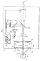
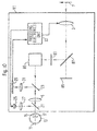
- Figure 1 is a schematic diagram of a surgical microscope 1.
- the microscope 1 comprises an objective lens 3 and an eyepiece 5, both of which are illustrated schematically by a single lens but which will, in practice, comprise a number of lenses.
- the objective lens 3 operates to generate an image of an object 7 being examined at an intermediate image plane (illustrated by the dashed line 9) which, in this embodiment is located at the focal plane of the eyepiece 5.
- an intermediate image plane illustrated by the dashed line 9
- the object 7 viewed by the observer appears to be at "infinity", i.e. the light from the object 7 emerges from the eyepiece 5 parallel to the optical axis 10 of the microscope.
- This image is then focussed by the cornea 15 and the eye lens 17 onto the retina 11 of the observer's eye 13.
- the microscope 1 also comprises two beam splitters 21 and 23 both of which are optically located along the optical axis 10 of the microscope 1.
- Beam splitter 21 operates to reflect light from an illumination source 25 onto the cornea 15 of the observer's eye 13.
- a lens 27 is provided between the illumination source 25 and the beam splitter 21 for focussing the light from the source 25 substantially onto the focal point 8 of the eyepiece 5, resulting in the light from the source 25 which exits the eyepiece 5 being substantially parallel to the axis 10 of the microscope.
- Some of this illumination light will be reflected from the surface of the cornea 15 back through the eyepiece 5 towards the beam splitter 23, where it is reflected and focussed onto a CCD sensor 29 by lens 31.
- the image generated by the CCD sensor 29 is input to a processing electronics unit 33, which is operable, in this embodiment, to process the received image to determine the observer's direction of gaze and to control the auto-focussing of the objective lens 3 in response thereto.
- the system can identify the direction of gaze at a resolution of approximately ⁇ 3% of the full field of view of the microscope, which is around what would be expected for natural saccadic movements of the eye. This implies that the tracking technique itself has a resolution that is potentially better than this figure.
- separate light sources 35a and 35b and 37a and 37b are provided around the outer rim of the eyepiece 5.
- the light sources 25, 35 and 37 emit near Infra Red (IR) light, since this is invisible to the user's eye and should not therefore, result in any reduction of the pupil size or in the quality of the image observed through the microscope.
- these sources are provided by high powered 850nm LED's which are operable to output about 0.2 mW at the front surface of the eye, which is well within current eye safety regulations.
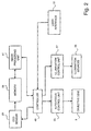
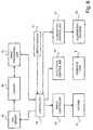
- FIG. 2 is a block diagram illustrating the principal components of the eye tracking system used in the present embodiment to determine the observer's direction of gaze.
- the output image from the CCD camera 29 is supplied to a memory 39 where it is processed by an image processing unit 41 to determine the observer's direction of gaze. This is achieved by monitoring the position of the reflected image of the illumination source 25 relative to the centre of the observer's pupil.
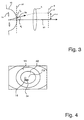
- Figure 3 schematically shows a cross section of the observer's eye showing the cornea 15, the iris 14, the eyepiece 5 and the intermediate image plane 9.
- the angle of gaze ⁇ x is related to the distance (x) between the optical axis 10 of the microscope 1 and the point (p) on the intermediate image plane 9 the observer is looking at. If the CCD camera 29 is focussed on the front surface of the observer's eye, i.e. at the plane 16, then the angle of gaze ( ⁇ x ) will also be dependent upon the distance ( ⁇ x) between the point of intersection of the axis 10 of the microscope and the plane 16 and the observed centre of the observer's pupil (c p ). Consequently, there will be a linear relationship between ⁇ x and x.
- Figure 3 illustrates a cross section of the microscope in the x-z plane
- a similar relationship exists for the angle of gaze ( ⁇ y ) in the y-z plane.
- the system uses a calibration routine (which the observer can initiate via the user interface 51) in which the observer is asked to look at a plurality of known points on the field of view of the microscope and in which the CCD camera 29 captures images of the observer's eye when the observer is looking at each of those points.
- a calibration routine which the observer can initiate via the user interface 51
- the CCD camera 29 captures images of the observer's eye when the observer is looking at each of those points.
- a scaling A x and an offset O x which relates ⁇ x to x and a scaling A y and an offset O y which relates ⁇ y to y can be determined. These scalings and offsets are then stored for use when the microscope is in its normal mode of operation.
- the observer's eye is located on the optical axis of the microscope.
- the light from the light source 25 exits the eyepiece 5 as a columnated beam, a similar relationship will exist if the observer's eye is off the axis of the microscope. Therefore, the system will be relatively insensitive to small head movements around the optical axis.
- Figure 4 schematically illustrates an example of the image generated by the CCD camera 29.
- the image shows the iris 14 and a reflection or highlight 18 of the illumination source 25 from the surface of the eye.
- Figure 4 also illustrates the distance ⁇ x between the highlight 18 and the centre of the pupil 22 at point c p .
- this distance can be determined by simple image processing techniques. Therefore, by capturing an image of the observer's eye and by measuring the distance ⁇ x and the corresponding distance ⁇ y, the point (x,y) that the observer is looking at on the image plane 9 can be determined using the stored scalings and offsets. The inventors have established through experimentation and testing with various user's that this technique can determine the observer's angle of gaze within approximately ⁇ 3% of the full field of view of the microscope.
- FIG 5a is a flowchart illustrating the processing steps employed by the controller 49 shown in Figure 2.
- the controller 49 signals the illumination control unit 57 to turn on the light source 25 and a first pair of the side light sources 35a and 35b.
- the controller 49 then signals, in step S3, the CCD camera 29 to capture a first image of the observer's eye which is then stored in the memory 39.
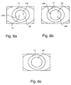
- Figure 6a illustrates the image generated by the CCD camera in this step. As shown, the image has three highlights - a central highlight 18 from the light source 25 and two outer highlights 24a and 24b generated by the light sources 35a and 35b respectively.
- the controller 49 then signals, in step S5, the illumination control unit 57 to switch off the light sources 25 and 35 and in step S7, to switch on the other pair of side illumination sources 37a and 37b. Then, in step S9, the controller 49 signals the CCD camera 29 to capture a second image of the observer's eye which is also then stored in memory 39.
- Figure 6b schematically illustrates the resulting image captured by the CCD camera 29, which shows the outer highlights 26a and 26b generated from the illumination sources 37a and 37b respectively.
- the processing then proceeds to step S11 where the controller 49 instructs the image processing unit 41 to determine the observer's direction of gaze from the two stored images. Once the image processing unit 41 determines this gaze information, it passes it back to the controller 49 which, in step S13 takes the necessary control action. In this embodiment, this involves controlling the focus of the objective lens 3 using the auto-focus control unit 55.
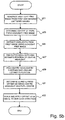
- Figure 5b is a flow chart illustrating the processing steps employed by the image processing unit 31 to determine the observer's direction of gaze.
- the image processing unit 41 generates a highlight free image from the first and second images stored in memory 39 (images shown in Figures 6a and 6b), by taking the lower of the pixel values from the two images, at each pixel.
- This highlight free image is shown in Figure 6c.
- This technique works since the highlights 18, 24 and 26 appear at different pixel locations in the two images and since the pupil is much darker than the highlights, the pixel values of the highlights will be much larger.
- the processing then proceeds to step S23 where the image processing unit 41 determines the centre of the pupil 22 from the highlight free image. It does this, in this embodiment, by thresholding the image to identify the boundary between the pupil 22 and the iris 14. A best fit circle is then fitted to the identified boundary and the centre of this circle is identified as being the pupil centre.
- step S25 the image processing unit extracts the highlights 18, 24a and 24b from the first image by subtracting the highlight free image shown in Figure 6c from the image shown in Figure 6a (i.e. subtracting the pixel values of the image shown in Figure 6c from the pixel values of the image shown in Figure 6a).
- step S27 the image processing unit determines the position of the outer highlights 24a and 24b by thresholding the image generated in step S25. From the determined position of the outer highlights 24, the image processing unit 41 estimates the position of the centre highlight 18. It can do this, since the illumination source 25 (which generates the centre highlight 18) and the illumination sources 35a and 35b (which generate the outer highlights 24) are in a known fixed position relative to each other.
- the illumination sources 35a and 35b are diametrically opposite each other on the outer rim of the eyepiece 5 and illumination source 25 is effectively on the optical axis of the microscope. Therefore, the position is estimated to be halfway between the two outer highlights.
- the processing then proceeds to step S29 where the image processing unit 41 determines a more accurate position of the centre highlight 18 by thresholding the image around the estimated position.
- the image processing unit 41 determines, in step S31, ⁇ x and ⁇ y from the determined positions of the centre highlight 18 and the pupil centre.
- step S33 the image processing unit scales ⁇ x and ⁇ y by using the stored scalings A x and A y and applies the appropriate offsets O x and O y to give the gaze direction in terms of the x,y co-ordinate of the point in the field of view 9 that the observer is looking at.
- the above processing steps are performed at approximately 25 times per second.
- the above described eye tracking technique works well in this microscope application because the observer's eye is usually located, in use, at approximately the same position relative to the eyepiece 5.
- This technique is also particularly appropriate for use in microscopes and other optical instruments in which the observer is viewing an image that appears essentially at infinity, since the x,y position on the image plane where the observer is looking is simply determined by the angle of gaze. Further, if the image is genuinely at infinity, then small head movements will have no effect on the observer's angle of gaze.
- information relating to the angle of gaze of the observer can be obtained by measuring the difference in the position of the pupil centre with respect to any of the highlights produced from any of the illumination sources.
- a highlight generated by a source (source 25) that is also effectively at infinity provides much more accurate results.
- the highlight is produced near the centre of the corneal bulge, where the radius of curvature of the cornea is relatively constant.
- the relatively large variations in curvature of the cornea that occur near the transition point from the corneal bulge to the rest of the eyeball have little effect on the measurement.
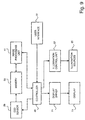
- FIG. 7 shows the processing blocks used in an embodiment where the gaze information is used to control the movement of the microscope 1. Processing blocks which are the same as those described with reference to Figure 2 have the same reference numeral. As shown, the only difference in this embodiment is the provision of a servo-controller 65 which is operable to receive the gaze information output by the controller 49 and in response thereto, is operable to control the operation of a number of motors 67 which move the microscope over the object 7 being viewed.
- Figure 8 shows the form of the processing and control electronics used in a further embodiment of the invention. As shown in Figure 8, in this embodiment, the determined direction of gaze information is used to control the positioning of the microscope and the focussing of the objective lens 3.
- Figure 9 shows the processing and control blocks used in yet another embodiment of the present invention.
- the direction of gaze information obtained by the controller is passed to a display driver 71 which controls the display of menus on a display 73 which is located within the viewfinder of the microscope.
- the CCD camera 29 was focussed onto the plane 16 shown in Figure 3. Provided the depth of field of the CCD camera is relatively large, the observer's eye does not have to be exactly at the plane 16 for the observer's eye to be in focus.
- the CCD camera 29 may have an associated autofocussing circuitry which operates to automatically focus the CCD camera onto the front surface of the observer's eye.
- the lens system for the CCD camera would either have to be telecentric or the calibration data would have to be adapted in dependence upon the current focus point of the CCD camera. This can be done, for example, by making the observer look at the calibration points for various different distances from the eyepiece 5, in order to determine the relationship between the calibration data and the focus point of the CCD camera.
- two pairs of side illumination sources 35 and 37 were provided on the outer rim of the eyepiece 5, for illuminating the observer's eye.
- illumination of the observer's eye can be achieved through the use of a single illumination source on the rim of the eyepiece. However, this is not preferred, since illumination from a single source does not provide uniform illumination of the observer's eye.
- the glints from these sources in the image can be removed by combining the images generated when only one of the side lights is switched on at any one time.
- FIG. 10 shows a schematic diagram of a camera 81 which employs the eye tracking technique discussed above.
- the camera 81 comprises an objective lens 3 for focussing the object onto the intermediate image plane.
- a real image is generated at the intermediate image plane by locating a diffusing screen 83 at the intermediate plane.
- the real image formed on the diffusing screen 83 is then viewed by the observer through the eyepiece 5 and a prism 85 which operates to reorientate the image the right way up.
- the camera 81 also has a mirror 87 which can be moved up or down so that the light from the object can be focussed onto the film 89.
- the remaining components of the eye tracking system are the same as those used in the microscope embodiments described above and will not, therefore, be described again. It should, however, be noted that, in this embodiment, the CCD sensor 29 and lens 31 are located in front of the diffusing screen 83, because the eye image cannot pass through the diffusing screen 83.
- calibration data was stored for each observer.
- the calibration data of one observer could be used for one or more other observers.
- such an embodiment is not preferred since the results will not be as accurate for the other observers. This is because the calibration data for an observer is dependent upon the radius of curvature of the observer's corneal bulge. The accuracy of such common calibration data may be improved if it is obtained by averaging several observer's calibration data.
- the system automatically changed the focus of the objective lens if the observer's direction of gaze moved to a position in the field of view which was out of focus.
- the processing electronics may be arranged so that the automatic focussing only changes either if the user remains focussed at the same point for a predetermined length of time or if the observer inputs a control command signalling that he wishes the focus to be changed.
- a beam splitter was used to effectively place the CCD sensor and the sensor lens on the axis of the microscope.
- the CCD sensor and the sensor lens can be located off the optical axis 10 of the microscope, provided the CCD sensor can still "see" the observer's eye.
- the CCD sensor is relatively small compared to the diameter of the objective lens, then the CCD sensor can be placed along the axis 10 of the objective lens.
- this embodiment is not preferred because it reduces the amount of light entering the observer's eye.
- the illumination source 25 may be located off the optical axis 10 of the microscope, provided the light from it will hit the observer's eye and be reflected back into the microscope and onto the CCD sensor.
Abstract
Description
Claims (36)
- An optical instrument for forming a viewable image of an object (7), comprising:characterised in that said eye sensor comprises:means (3) for forming a viewable image of the object (7) at an image plane (9);an eyepiece (5) through which the user can view said viewable image at said image plane (9);an eye sensor for sensing a direction of gaze of a user viewing the viewable image through said eyepiece (5); andmeans for adjusting a controllable function of said optical instrument in dependence upon the sensed direction of gaze;(i) a light source (25) for outputting light through said eyepiece towards the user's eye;(ii) a lens (27) associated with said light source for causing the light from said source to be substantially collimated when it exits said eyepiece towards said user's eye;(iii) an imaging transducer (5), (23), (31), (29) for imaging the front of the user's eye through said eyepiece and for generating an electrical image signal of the front of the user's eye; and(iv) processing means (33) for processing the electrical image signal from said imaging transducer (5), (23), (31), (29) to determine the distance between the location, within the image, of the user's pupil centre and the location, within the image, of a reflection of the light from said light source off the user's eye, and to determine said gaze information using said distance and predetermined calibration data which defines a relationship between said distance and the point on the image plane (9) the user is currently looking at.
- An instrument according to claim 1, wherein said eyepiece comprises a lens system for increasing the apparent field of view of the optical instrument.
- An instrument according to claim 2, wherein said lens associated with said light source is operable to focus the light from said light source substantially at the focal point of said eyepiece lens system.
- An instrument according to claim 2 or 3, wherein said forming means is operable to form said viewable image at an image plane which is located substantially at the focal point of said eyepiece lens system.
- An instrument according to any preceding claim, wherein said imaging transducer is located off the optical axis of said optical instrument.
- An instrument according to claim 5, further comprising a beam splitter for reflecting the light reflected from the front of the user's eye onto said imaging transducer.
- An instrument according to any preceding claim, wherein said imaging transducer comprises a CCD sensor.
- An instrument according to claim 7, wherein said CCD sensor comprises a 2D CCD sensor.
- An instrument according to claim 7 or 8, wherein said imaging transducer further comprises a lens for focussing the light from the user's eye onto said CCD sensor.
- An instrument according to claim 9, wherein said imaging transducer lens is operable to focus at a plane located at a predetermined distance in front of said eyepiece.
- An instrument according to claim 9, wherein said imaging transducer further comprises autofocus means for automatically focussing said imaging transducer lens on the front surface of said user's eye.
- An instrument according to any preceding claim, further comprising one or more further light sources for illuminating the user's eye.
- An instrument according to claim 12, wherein said one or more further light sources are located around an outer rim of said eyepiece.
- An instrument according to claim 12, wherein two pairs of additional light sources are provided around said rim.
- An instrument according to any preceding claim, wherein the or each of said light sources is operable to generate near infra-red light.
- An instrument according to claim 15, wherein the or each light source comprises an 850nm LED.
- An instrument according to any preceding claim, wherein said processing means is operable to determine said pupil centre by thresholding the image to locate the boundary between the pupil and the iris and by identifying the centre of the circle which best fits the located boundary.
- An instrument according to claim 1, wherein said calibration data is generated in advance during a calibration routine in which the user looks at different preselected locations on the image plane and in which the processing means is operable to correlate the determined distances from the corresponding images with the known points.
- An instrument according to claim 1 or 18, wherein said calibration data comprises a scaling factor for scaling said distance between said two locations.
- An instrument according to claim 19, wherein said calibration data comprises a scaling factor for an x component of said distance and a scaling factor for a y component of said distance.
- An instrument according to claim 20, wherein said calibration data further comprises an offset for said x direction and an offset for said y direction.
- An instrument according to claim 11, comprising means for varying said calibration data in dependence upon a current focal point of said imaging transducer lens.
- An instrument according to any preceding claim, wherein at least two further light sources are provided for illuminating the user's eye and wherein the instrument further comprises illumination control means for selectively illuminating different ones of said two or more further light sources and wherein said imaging transducer is operable to generate an image of the user's eye when different ones of said further light sources are illuminated and is operable to generate a highlight-free image by combining the images output from said transducer when the different light sources are illuminated.
- An instrument according to claim 23, wherein said processing means is operable to determine the centre of said pupil from said highlight-free image.
- An instrument according to claim 23 or 24, wherein said illumination control means is operable to illuminate a first pair of said further light sources during a first time interval and is operable to illuminate a second different pair of light sources during a second time interval and wherein said imaging transducer is operable to generate an image of the user's eye during said first time interval and during said second time interval.
- An instrument according to claim 25, wherein said illumination control means is operable to switch on said light source for outputting light through said eyepiece during said first time interval and wherein said processing means is operable to determine the location of said reflection by locating the reflections from said first pair of further light sources and then by estimating the position of said reflection from those locations and by thresholding the image around said estimated position.
- An instrument according to any preceding claim, wherein said light source for outputting light through said eyepiece is located off the axis of said optical instrument.
- An instrument according to claim 27, further comprising a beam splitter located on the optical axis of the instrument for reflecting the light from said source onto the user's eye.
- An instrument according to any preceding claim, wherein said imaging transducer is operable to output an image signal a plurality of times per second and wherein said processing means is operable to determine repeatedly said gaze information from said images.
- An instrument according to claim 29, wherein said imaging transducer is operable to output an image signal between ten and fifty times per second.
- An instrument according to any .preceding claim, wherein said controllable function is the automatic focussing of an objective lens forming part of said forming means so that the point in the field of view which the user is looking at is in focus.
- An instrument according to any preceding claim, wherein said controllable function is the movement of the optical instrument over the object being viewed.
- An instrument according to any preceding claim, wherein said controllable function is the content of a display which is optically superimposed on the field of view of the instrument.
- An instrument according to any preceding claim which is a microscope.
- An instrument according to any preceding claim which is a camera.
- A method of operating an optical instrument for forming a viewable image of an object (7), comprising the steps of:characterised in that said sensing step comprises the steps of:forming a viewable image of the object (7) at an image plane (9);viewing the viewable image through an eyepiece (5);sensing a direction of gaze of a user viewing the image (9); andcontrolling a controllable function of the optical instrument in dependence upon the sensed direction of gaze;(i) using a light source (25) to output light through said eyepiece (5) towards the user's eye;(ii) providing a lens (27) associated with said light source for causing the light from said source to be substantially collimated when it exits said eyepiece (5) towards said user's eye;(iii) providing an imaging transducer (5), (23), (31), (29) for imaging the front of the user's eye through said eyepiece (5) for generating an electrical image signal of the front of the user's eye; and(iv) processing the electrical image signal from said imaging transducer (5), (23), (31), (29) to determine the distance between the location, within the image of the user's pupil centre and the location, within the image, of a reflection of the light from said light source off the user's eye and to determine said gaze information using said distance and predetermined calibration data which defines a relationship between said distance and the point on the image plane (9) the user is currently looking at.
Applications Claiming Priority (3)
| Application Number | Priority Date | Filing Date | Title |
|---|---|---|---|
| GB9823977A GB9823977D0 (en) | 1998-11-02 | 1998-11-02 | Eye tracking method and apparatus |
| GB9823977 | 1998-11-02 | ||
| PCT/GB1999/003625 WO2000026713A1 (en) | 1998-11-02 | 1999-11-02 | Eye tracking system |
Publications (2)
| Publication Number | Publication Date |
|---|---|
| EP1131663A1 EP1131663A1 (en) | 2001-09-12 |
| EP1131663B1 true EP1131663B1 (en) | 2004-08-11 |
Family
ID=10841712
Family Applications (1)
| Application Number | Title | Priority Date | Filing Date |
|---|---|---|---|
| EP99954129A Revoked EP1131663B1 (en) | 1998-11-02 | 1999-11-02 | Eye tracking system |
Country Status (8)
| Country | Link |
|---|---|
| US (1) | US6634749B1 (en) |
| EP (1) | EP1131663B1 (en) |
| JP (1) | JP2002529763A (en) |
| AT (1) | ATE273525T1 (en) |
| AU (1) | AU1056800A (en) |
| DE (1) | DE69919383T2 (en) |
| GB (1) | GB9823977D0 (en) |
| WO (1) | WO2000026713A1 (en) |
Families Citing this family (53)
| Publication number | Priority date | Publication date | Assignee | Title |
|---|---|---|---|---|
| US7076118B1 (en) * | 1997-12-05 | 2006-07-11 | Sharp Laboratories Of America, Inc. | Document classification system |
| US7011410B2 (en) * | 2000-11-22 | 2006-03-14 | Eyetect, L.L.C. | Method and apparatus for monitoring eye tremor |
| US6478425B2 (en) * | 2000-12-29 | 2002-11-12 | Koninlijke Phillip Electronics N. V. | System and method for automatically adjusting a lens power through gaze tracking |
| AU2002361210A1 (en) | 2001-12-21 | 2003-07-09 | Sensomotoric Instruments Gmbh | Method and apparatus for eye registration |
| US7197165B2 (en) | 2002-02-04 | 2007-03-27 | Canon Kabushiki Kaisha | Eye tracking using image data |
| DE10250569A1 (en) | 2002-10-28 | 2004-05-13 | Carl Zeiss Meditec Ag | Ophthalmic device and device positioning method |
| ATE359533T1 (en) * | 2003-02-17 | 2007-05-15 | Topcon Corp | OPHTHALMO-SURGICAL MICROSCOPE |
| US20040174497A1 (en) * | 2003-03-07 | 2004-09-09 | Manish Sharma | Method and system for controlling the movement of a device |
| US8292433B2 (en) * | 2003-03-21 | 2012-10-23 | Queen's University At Kingston | Method and apparatus for communication between humans and devices |
| US7762665B2 (en) | 2003-03-21 | 2010-07-27 | Queen's University At Kingston | Method and apparatus for communication between humans and devices |
| US7731360B2 (en) * | 2003-11-07 | 2010-06-08 | Neuro Kinetics | Portable video oculography system |
| US20060279745A1 (en) * | 2005-06-13 | 2006-12-14 | Wenstrand John S | Color imaging system for locating retroreflectors |
| JP4797588B2 (en) * | 2005-11-17 | 2011-10-19 | アイシン精機株式会社 | Vehicle periphery display device |
| JP4356733B2 (en) * | 2006-11-09 | 2009-11-04 | アイシン精機株式会社 | In-vehicle image processing apparatus and control method thereof |
| US9655515B2 (en) * | 2008-04-08 | 2017-05-23 | Neuro Kinetics | Method of precision eye-tracking through use of iris edge based landmarks in eye geometry |
| US10398309B2 (en) | 2008-10-09 | 2019-09-03 | Neuro Kinetics, Inc. | Noninvasive rapid screening of mild traumatic brain injury using combination of subject's objective oculomotor, vestibular and reaction time analytic variables |
| US8585609B2 (en) * | 2008-10-09 | 2013-11-19 | Neuro Kinetics, Inc. | Quantitative, non-invasive, clinical diagnosis of traumatic brain injury using simulated distance visual stimulus device for neurologic testing |
| US9039631B2 (en) | 2008-10-09 | 2015-05-26 | Neuro Kinetics | Quantitative, non-invasive, clinical diagnosis of traumatic brain injury using VOG device for neurologic testing |
| US20100295782A1 (en) | 2009-05-21 | 2010-11-25 | Yehuda Binder | System and method for control based on face ore hand gesture detection |
| IT1399456B1 (en) * | 2009-09-11 | 2013-04-19 | Sr Labs S R L | METHOD AND APPARATUS FOR THE USE OF GENERIC SOFTWARE APPLICATIONS THROUGH EYE CONTROL AND INTERACTION METHODS IS APPROPRIATE. |
| DE102010038547B4 (en) * | 2010-07-28 | 2012-07-19 | Leica Microsystems (Schweiz) Ag | Image stabilization and recording sensor for an image pickup device of a surgical microscope |
| KR101824501B1 (en) * | 2011-05-19 | 2018-02-01 | 삼성전자 주식회사 | Device and method for controlling display of the image in the head mounted display |
| US8885882B1 (en) | 2011-07-14 | 2014-11-11 | The Research Foundation For The State University Of New York | Real time eye tracking for human computer interaction |
| EP2551636A1 (en) * | 2011-07-25 | 2013-01-30 | Leica Geosystems AG | Contact-free measuring device and method for controlling the same |
| CN102914932A (en) * | 2011-08-03 | 2013-02-06 | 浪潮乐金数字移动通信有限公司 | Photographic device and method for focusing by eyes of photographic device user |
| US9102269B2 (en) | 2011-08-09 | 2015-08-11 | Continental Automotive Systems, Inc. | Field of view matching video display system |
| US8808179B1 (en) | 2012-08-06 | 2014-08-19 | James Z. Cinberg | Method and associated apparatus for detecting minor traumatic brain injury |
| US9265458B2 (en) | 2012-12-04 | 2016-02-23 | Sync-Think, Inc. | Application of smooth pursuit cognitive testing paradigms to clinical drug development |
| US9380976B2 (en) | 2013-03-11 | 2016-07-05 | Sync-Think, Inc. | Optical neuroinformatics |
| CA2882413C (en) * | 2013-03-18 | 2016-10-25 | Mirametrix Inc. | System and method for on-axis eye gaze tracking |
| US9261959B1 (en) | 2013-03-28 | 2016-02-16 | Google Inc. | Input detection |
| EP2787323A1 (en) * | 2013-04-05 | 2014-10-08 | Leica Geosystems AG | Measuring device with function for calibrating a display image position of an electronic reticule |
| US8922589B2 (en) | 2013-04-07 | 2014-12-30 | Laor Consulting Llc | Augmented reality apparatus |
| CN106062665B (en) * | 2013-09-11 | 2019-05-17 | 深圳市汇顶科技股份有限公司 | The user interface of optical sensing and the tracking of eye motion and position based on user |
| US9557553B2 (en) * | 2013-10-10 | 2017-01-31 | Raytheon Canada Limited | Electronic eyebox |
| EP3065623B1 (en) | 2013-11-09 | 2020-04-22 | Shenzhen Goodix Technology Co., Ltd. | Optical eye tracking |
| KR101855196B1 (en) | 2013-11-27 | 2018-06-08 | 선전 구딕스 테크놀로지 컴퍼니, 리미티드 | Eye tracking and user reaction detection |
| WO2015086617A1 (en) * | 2013-12-09 | 2015-06-18 | SensoMotoric Instruments Gesellschaft für innovative Sensorik mbH | Method for operating an eye tracking device and eye tracking device for providing an active illumination control for improved eye tracking robustness |
| US9292765B2 (en) | 2014-01-07 | 2016-03-22 | Microsoft Technology Licensing, Llc | Mapping glints to light sources |
| US9782069B2 (en) | 2014-11-06 | 2017-10-10 | International Business Machines Corporation | Correcting systematic calibration errors in eye tracking data |
| DK179537B1 (en) * | 2015-02-04 | 2019-02-08 | Itu Business Development A/S | Tin traces and eye tracking methods |
| WO2016180702A1 (en) * | 2015-05-08 | 2016-11-17 | SensoMotoric Instruments Gesellschaft für innovative Sensorik mbH | Eye tracking device and method for operating an eye tracking device |
| KR102345652B1 (en) * | 2015-06-26 | 2021-12-30 | 삼성전자주식회사 | View finder apparatus and method for the same |
| CN107710050A (en) | 2015-06-30 | 2018-02-16 | 3M创新有限公司 | Luminaire |
| US10635901B2 (en) | 2015-08-11 | 2020-04-28 | Sony Interactive Entertainment Inc. | Head-mounted display |
| DE102015118154A1 (en) | 2015-10-23 | 2017-04-27 | Arnold & Richter Cine Technik Gmbh & Co. Betriebs Kg | Electronic microscope, in particular surgical microscope |
| CN105954992B (en) * | 2016-07-22 | 2018-10-30 | 京东方科技集团股份有限公司 | Display system and display methods |
| ES2943719T3 (en) * | 2016-07-27 | 2023-06-15 | Tobii Ab | Wearable device having a display, lens, illuminator, and image sensor |
| KR20180050143A (en) | 2016-11-04 | 2018-05-14 | 삼성전자주식회사 | Method and device for acquiring information by capturing eye |
| US10176375B2 (en) | 2017-03-29 | 2019-01-08 | Raytheon Canada Limited | High speed pupil detection system and method |
| CN110251078A (en) * | 2019-01-30 | 2019-09-20 | 北京大学第三医院(北京大学第三临床医学院) | Microscopical imaging method, imaging system and microscope |
| CN110441901A (en) * | 2019-08-14 | 2019-11-12 | 东北大学 | It is a kind of can real-time tracing watch the optical microscope system and method for position attentively |
| FI130771B1 (en) * | 2020-07-03 | 2024-03-07 | Seetrue Tech Oy | Gaze tracking |
Family Cites Families (18)
| Publication number | Priority date | Publication date | Assignee | Title |
|---|---|---|---|---|
| JPS542115A (en) | 1977-06-07 | 1979-01-09 | Fuji Photo Film Co Ltd | Data imprinting device for cameras |
| US4322752A (en) | 1980-01-16 | 1982-03-30 | Eastman Technology, Inc. | Fast frame rate sensor readout |
| IL87813A (en) | 1987-09-21 | 1993-08-18 | Udden | Measuring light intensity variations |
| US5016282A (en) * | 1988-07-14 | 1991-05-14 | Atr Communication Systems Research Laboratories | Eye tracking image pickup apparatus for separating noise from feature portions |
| US5231674A (en) * | 1989-06-09 | 1993-07-27 | Lc Technologies, Inc. | Eye tracking method and apparatus |
| US4974010A (en) * | 1989-06-09 | 1990-11-27 | Lc Technologies, Inc. | Focus control system |
| FR2672989A1 (en) | 1991-02-15 | 1992-08-21 | Sodern | DEVICE FOR DETERMINING THE DIRECTION OF A LOW - BRIGHT EMISSIVE SOURCE AND ITS APPLICATION TO THE STELLAR VISEE. |
| JPH0761314B2 (en) * | 1991-10-07 | 1995-07-05 | コナミ株式会社 | Retinal reflected light amount measuring device and eye gaze detecting device using the device |
| US5360971A (en) * | 1992-03-31 | 1994-11-01 | The Research Foundation State University Of New York | Apparatus and method for eye tracking interface |
| EP0863431B1 (en) | 1992-06-02 | 2004-10-20 | Canon Kabushiki Kaisha | Optical apparatus for detecting rotation of an eyeball of an observer |
| EP0588290A3 (en) | 1992-09-14 | 1994-05-18 | Nippon Kogaku Kk | Camera with sight line detecting device |
| JPH0694978A (en) | 1992-09-14 | 1994-04-08 | Nikon Corp | Device for detecting line of sight |
| JPH06138379A (en) | 1992-09-14 | 1994-05-20 | Nikon Corp | Camera provided with device for detecting line of sight |
| JPH06148513A (en) | 1992-10-30 | 1994-05-27 | Canon Inc | Line-of-sight detector |
| FR2719988B1 (en) | 1994-05-20 | 1996-08-02 | Centre Nat Rech Scient | Eye movement control device. |
| US5867308A (en) | 1994-10-26 | 1999-02-02 | Leica Mikroskopie Systeme Ag | Microscope, in particular for surgical operations |
| US5726916A (en) * | 1996-06-27 | 1998-03-10 | The United States Of America As Represented By The Secretary Of The Army | Method and apparatus for determining ocular gaze point of regard and fixation duration |
| CA2233047C (en) * | 1998-02-02 | 2000-09-26 | Steve Mann | Wearable camera system with viewfinder means |
-
1998
- 1998-11-02 GB GB9823977A patent/GB9823977D0/en not_active Ceased
-
1999
- 1999-11-02 US US09/830,828 patent/US6634749B1/en not_active Expired - Lifetime
- 1999-11-02 AT AT99954129T patent/ATE273525T1/en not_active IP Right Cessation
- 1999-11-02 JP JP2000580037A patent/JP2002529763A/en active Pending
- 1999-11-02 WO PCT/GB1999/003625 patent/WO2000026713A1/en not_active Application Discontinuation
- 1999-11-02 EP EP99954129A patent/EP1131663B1/en not_active Revoked
- 1999-11-02 AU AU10568/00A patent/AU1056800A/en not_active Abandoned
- 1999-11-02 DE DE1999619383 patent/DE69919383T2/en not_active Revoked
Also Published As
| Publication number | Publication date |
|---|---|
| WO2000026713A1 (en) | 2000-05-11 |
| DE69919383T2 (en) | 2005-12-01 |
| EP1131663A1 (en) | 2001-09-12 |
| GB9823977D0 (en) | 1998-12-30 |
| ATE273525T1 (en) | 2004-08-15 |
| US6634749B1 (en) | 2003-10-21 |
| JP2002529763A (en) | 2002-09-10 |
| DE69919383D1 (en) | 2004-09-16 |
| AU1056800A (en) | 2000-05-22 |
Similar Documents
| Publication | Publication Date | Title |
|---|---|---|
| EP1131663B1 (en) | Eye tracking system | |
| US6394602B1 (en) | Eye tracking system | |
| KR102000865B1 (en) | A method for operating an eye tracking device and an eye tracking device | |
| JP2003521950A6 (en) | Target tracking system | |
| US5751396A (en) | Ophthalmic apparatus including ocular fundus illuminating system for illuminating the fundus of the eye to be examined through the pupil thereof | |
| US6191892B1 (en) | Image display apparatus | |
| US5225862A (en) | Visual axis detector using plural reflected image of a light source | |
| US5386258A (en) | Optical apparatus having a visual axis direction detecting device | |
| US7298414B2 (en) | Digital camera autofocus using eye focus measurement | |
| JPH11501403A (en) | Microscopes, especially surgical microscopes | |
| KR20020086590A (en) | System and method for automatically adjusting a lens power through gaze tracking | |
| JPH0846846A (en) | Image pickup device | |
| JP2009240551A (en) | Sight line detector | |
| JPH08286144A (en) | Picture observation device and observation equipment using the device | |
| US5973737A (en) | Apparatus having an eye control unit | |
| US5767821A (en) | Communication device | |
| WO1991006263A1 (en) | A communication device | |
| CN114342352A (en) | Electronic device, electronic device control method, program, and storage medium | |
| JPH10179520A (en) | Visual axis detecting method and device, and storage medium | |
| JPH09262210A (en) | Optical system | |
| JP3171698B2 (en) | Camera focal length control device | |
| JP3320123B2 (en) | Eye gaze detecting apparatus and method, and video camera | |
| JP3134320B2 (en) | Eye gaze detection device | |
| JP2995878B2 (en) | Optical device having line-of-sight detection device | |
| JPH02213322A (en) | Method and apparatus for detecting visual axis |
Legal Events
| Date | Code | Title | Description |
|---|---|---|---|
| PUAI | Public reference made under article 153(3) epc to a published international application that has entered the european phase |
Free format text: ORIGINAL CODE: 0009012 |
|
| 17P | Request for examination filed |
Effective date: 20010530 |
|
| AK | Designated contracting states |
Kind code of ref document: A1 Designated state(s): AT BE CH CY DE DK ES FI FR GB GR IE IT LI LU MC NL PT SE |
|
| GRAG | Despatch of communication of intention to grant |
Free format text: ORIGINAL CODE: EPIDOS AGRA |
|
| 17Q | First examination report despatched |
Effective date: 20011112 |
|
| GRAG | Despatch of communication of intention to grant |
Free format text: ORIGINAL CODE: EPIDOS AGRA |
|
| RAP1 | Party data changed (applicant data changed or rights of an application transferred) |
Owner name: LEICA MICROSYSTEMS SCHWEIZ AG |
|
| GRAP | Despatch of communication of intention to grant a patent |
Free format text: ORIGINAL CODE: EPIDOSNIGR1 |
|
| GRAU | Approval following communication of intention to grant |
Free format text: ORIGINAL CODE: EPIDOSNAGR4 |
|
| GRAS | Grant fee paid |
Free format text: ORIGINAL CODE: EPIDOSNIGR3 |
|
| GRAA | (expected) grant |
Free format text: ORIGINAL CODE: 0009210 |
|
| AK | Designated contracting states |
Kind code of ref document: B1 Designated state(s): AT BE CH CY DE DK ES FI FR GB GR IE IT LI LU MC NL PT SE |
|
| PG25 | Lapsed in a contracting state [announced via postgrant information from national office to epo] |
Ref country code: NL Free format text: LAPSE BECAUSE OF FAILURE TO SUBMIT A TRANSLATION OF THE DESCRIPTION OR TO PAY THE FEE WITHIN THE PRESCRIBED TIME-LIMIT Effective date: 20040811 Ref country code: IT Free format text: LAPSE BECAUSE OF FAILURE TO SUBMIT A TRANSLATION OF THE DESCRIPTION OR TO PAY THE FEE WITHIN THE PRESCRIBED TIME-LIMIT;WARNING: LAPSES OF ITALIAN PATENTS WITH EFFECTIVE DATE BEFORE 2007 MAY HAVE OCCURRED AT ANY TIME BEFORE 2007. THE CORRECT EFFECTIVE DATE MAY BE DIFFERENT FROM THE ONE RECORDED. Effective date: 20040811 Ref country code: FI Free format text: LAPSE BECAUSE OF FAILURE TO SUBMIT A TRANSLATION OF THE DESCRIPTION OR TO PAY THE FEE WITHIN THE PRESCRIBED TIME-LIMIT Effective date: 20040811 Ref country code: CY Free format text: LAPSE BECAUSE OF FAILURE TO SUBMIT A TRANSLATION OF THE DESCRIPTION OR TO PAY THE FEE WITHIN THE PRESCRIBED TIME-LIMIT Effective date: 20040811 Ref country code: BE Free format text: LAPSE BECAUSE OF FAILURE TO SUBMIT A TRANSLATION OF THE DESCRIPTION OR TO PAY THE FEE WITHIN THE PRESCRIBED TIME-LIMIT Effective date: 20040811 Ref country code: AT Free format text: LAPSE BECAUSE OF FAILURE TO SUBMIT A TRANSLATION OF THE DESCRIPTION OR TO PAY THE FEE WITHIN THE PRESCRIBED TIME-LIMIT Effective date: 20040811 |
|
| REG | Reference to a national code |
Ref country code: GB Ref legal event code: FG4D |
|
| REG | Reference to a national code |
Ref country code: CH Ref legal event code: EP |
|
| REG | Reference to a national code |
Ref country code: IE Ref legal event code: FG4D |
|
| REF | Corresponds to: |
Ref document number: 69919383 Country of ref document: DE Date of ref document: 20040916 Kind code of ref document: P |
|
| PG25 | Lapsed in a contracting state [announced via postgrant information from national office to epo] |
Ref country code: LU Free format text: LAPSE BECAUSE OF NON-PAYMENT OF DUE FEES Effective date: 20041102 Ref country code: IE Free format text: LAPSE BECAUSE OF NON-PAYMENT OF DUE FEES Effective date: 20041102 |
|
| PG25 | Lapsed in a contracting state [announced via postgrant information from national office to epo] |
Ref country code: SE Free format text: LAPSE BECAUSE OF FAILURE TO SUBMIT A TRANSLATION OF THE DESCRIPTION OR TO PAY THE FEE WITHIN THE PRESCRIBED TIME-LIMIT Effective date: 20041111 Ref country code: GR Free format text: LAPSE BECAUSE OF FAILURE TO SUBMIT A TRANSLATION OF THE DESCRIPTION OR TO PAY THE FEE WITHIN THE PRESCRIBED TIME-LIMIT Effective date: 20041111 Ref country code: DK Free format text: LAPSE BECAUSE OF FAILURE TO SUBMIT A TRANSLATION OF THE DESCRIPTION OR TO PAY THE FEE WITHIN THE PRESCRIBED TIME-LIMIT Effective date: 20041111 |
|
| PGFP | Annual fee paid to national office [announced via postgrant information from national office to epo] |
Ref country code: CH Payment date: 20041119 Year of fee payment: 6 |
|
| PG25 | Lapsed in a contracting state [announced via postgrant information from national office to epo] |
Ref country code: ES Free format text: LAPSE BECAUSE OF FAILURE TO SUBMIT A TRANSLATION OF THE DESCRIPTION OR TO PAY THE FEE WITHIN THE PRESCRIBED TIME-LIMIT Effective date: 20041122 |
|
| PGFP | Annual fee paid to national office [announced via postgrant information from national office to epo] |
Ref country code: GB Payment date: 20041122 Year of fee payment: 6 |
|
| PGFP | Annual fee paid to national office [announced via postgrant information from national office to epo] |
Ref country code: FR Payment date: 20041123 Year of fee payment: 6 |
|
| PG25 | Lapsed in a contracting state [announced via postgrant information from national office to epo] |
Ref country code: MC Free format text: LAPSE BECAUSE OF NON-PAYMENT OF DUE FEES Effective date: 20041130 |
|
| NLV1 | Nl: lapsed or annulled due to failure to fulfill the requirements of art. 29p and 29m of the patents act | ||
| ET | Fr: translation filed | ||
| PLAQ | Examination of admissibility of opposition: information related to despatch of communication + time limit deleted |
Free format text: ORIGINAL CODE: EPIDOSDOPE2 |
|
| PLBQ | Unpublished change to opponent data |
Free format text: ORIGINAL CODE: EPIDOS OPPO |
|
| PLAQ | Examination of admissibility of opposition: information related to despatch of communication + time limit deleted |
Free format text: ORIGINAL CODE: EPIDOSDOPE2 |
|
| PLAR | Examination of admissibility of opposition: information related to receipt of reply deleted |
Free format text: ORIGINAL CODE: EPIDOSDOPE4 |
|
| PLBI | Opposition filed |
Free format text: ORIGINAL CODE: 0009260 |
|
| PLBQ | Unpublished change to opponent data |
Free format text: ORIGINAL CODE: EPIDOS OPPO |
|
| PLAB | Opposition data, opponent's data or that of the opponent's representative modified |
Free format text: ORIGINAL CODE: 0009299OPPO |
|
| PLAQ | Examination of admissibility of opposition: information related to despatch of communication + time limit deleted |
Free format text: ORIGINAL CODE: EPIDOSDOPE2 |
|
| PLAR | Examination of admissibility of opposition: information related to receipt of reply deleted |
Free format text: ORIGINAL CODE: EPIDOSDOPE4 |
|
| PLBQ | Unpublished change to opponent data |
Free format text: ORIGINAL CODE: EPIDOS OPPO |
|
| PLAX | Notice of opposition and request to file observation + time limit sent |
Free format text: ORIGINAL CODE: EPIDOSNOBS2 |
|
| 26 | Opposition filed |
Opponent name: CARL ZEISS AG Effective date: 20050506 |
|
| R26 | Opposition filed (corrected) |
Opponent name: CARL ZEISS AG Effective date: 20050506 |
|
| REG | Reference to a national code |
Ref country code: IE Ref legal event code: MM4A |
|
| PLAF | Information modified related to communication of a notice of opposition and request to file observations + time limit |
Free format text: ORIGINAL CODE: EPIDOSCOBS2 |
|
| PG25 | Lapsed in a contracting state [announced via postgrant information from national office to epo] |
Ref country code: GB Free format text: LAPSE BECAUSE OF NON-PAYMENT OF DUE FEES Effective date: 20051102 |
|
| PG25 | Lapsed in a contracting state [announced via postgrant information from national office to epo] |
Ref country code: LI Free format text: LAPSE BECAUSE OF NON-PAYMENT OF DUE FEES Effective date: 20051130 Ref country code: CH Free format text: LAPSE BECAUSE OF NON-PAYMENT OF DUE FEES Effective date: 20051130 |
|
| PLBB | Reply of patent proprietor to notice(s) of opposition received |
Free format text: ORIGINAL CODE: EPIDOSNOBS3 |
|
| REG | Reference to a national code |
Ref country code: CH Ref legal event code: PL |
|
| GBPC | Gb: european patent ceased through non-payment of renewal fee |
Effective date: 20051102 |
|
| PG25 | Lapsed in a contracting state [announced via postgrant information from national office to epo] |
Ref country code: FR Free format text: LAPSE BECAUSE OF NON-PAYMENT OF DUE FEES Effective date: 20060731 |
|
| REG | Reference to a national code |
Ref country code: FR Ref legal event code: ST Effective date: 20060731 |
|
| PGFP | Annual fee paid to national office [announced via postgrant information from national office to epo] |
Ref country code: DE Payment date: 20061124 Year of fee payment: 8 |
|
| RDAF | Communication despatched that patent is revoked |
Free format text: ORIGINAL CODE: EPIDOSNREV1 |
|
| RDAG | Patent revoked |
Free format text: ORIGINAL CODE: 0009271 |
|
| STAA | Information on the status of an ep patent application or granted ep patent |
Free format text: STATUS: PATENT REVOKED |
|
| 27W | Patent revoked |
Effective date: 20070812 |
|
| PG25 | Lapsed in a contracting state [announced via postgrant information from national office to epo] |
Ref country code: PT Free format text: LAPSE BECAUSE OF NON-PAYMENT OF DUE FEES Effective date: 20050111 |