EP1133094A2 - Dynamic assignment of retransmission slots in wireless communication links - Google Patents
Dynamic assignment of retransmission slots in wireless communication links Download PDFInfo
- Publication number
- EP1133094A2 EP1133094A2 EP01000040A EP01000040A EP1133094A2 EP 1133094 A2 EP1133094 A2 EP 1133094A2 EP 01000040 A EP01000040 A EP 01000040A EP 01000040 A EP01000040 A EP 01000040A EP 1133094 A2 EP1133094 A2 EP 1133094A2
- Authority
- EP
- European Patent Office
- Prior art keywords
- communications
- retransmission
- packet
- wireless communication
- devices
- Prior art date
- Legal status (The legal status is an assumption and is not a legal conclusion. Google has not performed a legal analysis and makes no representation as to the accuracy of the status listed.)
- Granted
Links
Images


Classifications
-
- H—ELECTRICITY
- H04—ELECTRIC COMMUNICATION TECHNIQUE
- H04L—TRANSMISSION OF DIGITAL INFORMATION, e.g. TELEGRAPHIC COMMUNICATION
- H04L1/00—Arrangements for detecting or preventing errors in the information received
- H04L1/12—Arrangements for detecting or preventing errors in the information received by using return channel
- H04L1/16—Arrangements for detecting or preventing errors in the information received by using return channel in which the return channel carries supervisory signals, e.g. repetition request signals
- H04L1/18—Automatic repetition systems, e.g. Van Duuren systems
- H04L1/1809—Selective-repeat protocols
-
- H—ELECTRICITY
- H04—ELECTRIC COMMUNICATION TECHNIQUE
- H04L—TRANSMISSION OF DIGITAL INFORMATION, e.g. TELEGRAPHIC COMMUNICATION
- H04L1/00—Arrangements for detecting or preventing errors in the information received
- H04L1/0001—Systems modifying transmission characteristics according to link quality, e.g. power backoff
-
- H—ELECTRICITY
- H04—ELECTRIC COMMUNICATION TECHNIQUE
- H04L—TRANSMISSION OF DIGITAL INFORMATION, e.g. TELEGRAPHIC COMMUNICATION
- H04L1/00—Arrangements for detecting or preventing errors in the information received
- H04L1/0078—Avoidance of errors by organising the transmitted data in a format specifically designed to deal with errors, e.g. location
- H04L1/0083—Formatting with frames or packets; Protocol or part of protocol for error control
-
- H—ELECTRICITY
- H04—ELECTRIC COMMUNICATION TECHNIQUE
- H04L—TRANSMISSION OF DIGITAL INFORMATION, e.g. TELEGRAPHIC COMMUNICATION
- H04L1/00—Arrangements for detecting or preventing errors in the information received
- H04L1/12—Arrangements for detecting or preventing errors in the information received by using return channel
- H04L1/16—Arrangements for detecting or preventing errors in the information received by using return channel in which the return channel carries supervisory signals, e.g. repetition request signals
-
- H—ELECTRICITY
- H04—ELECTRIC COMMUNICATION TECHNIQUE
- H04L—TRANSMISSION OF DIGITAL INFORMATION, e.g. TELEGRAPHIC COMMUNICATION
- H04L1/00—Arrangements for detecting or preventing errors in the information received
- H04L2001/0092—Error control systems characterised by the topology of the transmission link
- H04L2001/0093—Point-to-multipoint
-
- H—ELECTRICITY
- H04—ELECTRIC COMMUNICATION TECHNIQUE
- H04W—WIRELESS COMMUNICATION NETWORKS
- H04W72/00—Local resource management
- H04W72/04—Wireless resource allocation
- H04W72/044—Wireless resource allocation based on the type of the allocated resource
- H04W72/0446—Resources in time domain, e.g. slots or frames
-
- H—ELECTRICITY
- H04—ELECTRIC COMMUNICATION TECHNIQUE
- H04W—WIRELESS COMMUNICATION NETWORKS
- H04W76/00—Connection management
- H04W76/10—Connection setup
Definitions
- the invention relates generally to wireless communications and, more particularly, to wireless communications that utilize retransmissions.
- Dutta-Roy discusses several communication protocols in the 2.4 GHz band, including IEEE 802.11 direct-sequence spread spectrum (DSSS) and frequency-hopping (FHSS) protocols.
- DSSS direct-sequence spread spectrum
- FHSS frequency-hopping
- a disadvantage of these protocols is the high overhead associated with their implementation.
- a less complex wireless protocol known as Shared Wireless Access Protocol (SWAP) also operates in the 2.4 GHz band. This protocol has been developed by the HomeRF Working Group and is supported by North American communications companies.
- SWAP Shared Wireless Access Protocol
- the SWAP protocol uses frequency-hopping spread spectrum technology to produce a data rate of 1 Mb/sec.
- Another less complex protocol is named Bluetooth after a 10th century Scandinavian king who united several Danish kingdoms. This protocol also operates in the 2.4 GHz band and advantageously offers short-range wireless communication between Bluetooth devices without the need for a central network.
- the Bluetooth protocol provides a 1 Mb/sec data rate with low energy consumption for battery powered devices operating in the 2.4 GHz ISM (industrial, scientific, medical) band.
- the current Bluetooth protocol provides a 10-meter range and a maximum asymmetric data transfer rate of 723 kb/sec.
- the protocol supports a maximum of three voice channels for synchronous, CVSD-encoded transmission at 64 kb/sec.
- the Bluetooth protocol treats all radios as peer units except for a unique 48-bit address.
- the initiating unit is a temporary master. This temporary assignment, however, may change after initial communications are established. Each master may have active connections of up to seven slaves.
- Bluetooth master devices include cordless phone base stations, local area network (LAN) access points, laptop computers, or bridges to other networks.
- Bluetooth slave devices may include cordless handsets, cell phones, headsets, personal digital assistants, digital cameras, or computer peripherals such as printers, scanners, fax machines and other devices.
- the Bluetooth protocol uses time-division duplex (TDD) to support bi-directional communication.
- Frequency hopping permits operation in noisy environments and permits multiple piconets to exist in close proximity.
- the frequency hopping scheme permits up to 1600 hops per second over 79 1-MHZ channels or the entire 2.4 GHz ISM spectrum.
- error correcting schemes permit data packet protection by 1/3 and 2/3 rate forward error correction.
- Bluetooth uses retransmission of packets for guaranteed reliability. These schemes help correct data errors, but at the expense of throughput.
- the Bluetooth protocol is specified in detail in Specification of the Bluetooth System, Version 1.0A, July 26, 1999, which is incorporated herein by reference.
- the Bluetooth specification calls for 64 kilobits/second CVSD speech coding on an SCO (Synchronous Connection-Oriented) link.
- SCO Synchronous Connection-Oriented
- the speech can be coded using a lower rate coder, and can then be treated as data for transmission on Bluetooth ACL (Asynchronous Connection-Less) links.
- ACL links allow retransmission of packets, which can provide enhanced quality relative to SCO links which do not allow retransmission of packets.
- the present invention recognizes the desireability of further improving the quality of speech transmission on Bluetooth ACL links and other wireless communication links. To this end, the invention advantageously provides for increasing the utilization and effectiveness of retransmission communications by dynamically assigning desired communications to the respective retransmission slots.
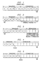
- FIGURE 1 diagrammatically illustrates an exemplary timing arrangement of transmissions and retransmissions in conventional Bluetooth ACL links.
- FIGURE 2 diagrammatically illustrates an exemplary timing arrangement of transmissions and retransmissions over Bluetooth ACL links according to the present invention.
- FIGURES 3-5 diagrammatically illustrate applications of the arrangement of FIGURE 2 wherein the amount of retransmissions varies inversely with the number of users.
- FIGURE 6 diagrammatically illustrates an exemplary application of the arrangement of FIGURE 2 wherein the communication direction of the retransmission slots is variable.
- FIGURE 7 illustrates a further exemplary application of the arrangement of FIGURE 2 wherein the same communication is transmitted in two retransmission slots.
- FIGURE 8 diagrammatically illustrates a further exemplary application of the arrangement of FIGURE 2 wherein a single retransmission slot is used for transmission of two separate communications.
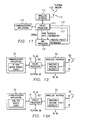
- FIGURE 9 diagrammatically illustrates pertinent portions of exemplary embodiments of the master device illustrated in FIGURES 2-8.
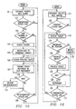
- FIGURE 10 illustrates exemplary operations which can be performed by the master device of FIGURE 9.
- FIGURE 11 diagrammatically illustrates pertinent portions of exemplary embodiments of the slave devices illustrated in FIGURES 2-8.
- FIGURE 12 illustrates exemplary operations which can be performed by the slave device of FIGURE 11.
- FIGURES 13 and 13A diagrammatically illustrate pertinent portions of further exemplary embodiments of the master device of FIGURE 9.
- FIGURES 14 and 14A diagrammatically illustrate pertinent portions of further exemplary embodiments of the slave device of FIGURE 11.
- FIGURE 15 illustrates exemplary simulation results associated with the embodiments of FIGURES 13 and 14.
- FIGURE 1 illustrates an exemplary transmission//retransmission timing arrangement associated with transmission of speech in the form of data packets transmitted over Bluetooth ACL links.
- M represents a Bluetooth master device and S1, S2 and S3 represent Bluetooth slave devices respectively associated with three users of a Bluetooth system.
- S1, S2 and S3 represent Bluetooth slave devices respectively associated with three users of a Bluetooth system.
- for each slave device there is reserved a master-to-slave transmission time slot, a corresponding slave-to-master transmission time slot, a master-to-slave retransmission time slot and a corresponding slave-to-master retransmission time slot. All of the available time slots in FIGURE 1 are thus pre-assigned to the three users associated with slave devices S1, S2 and S3.
- a master-to-slave transmission time slot and a slave-to-master transmission time slot are pre-assigned for each slave device in a Bluetooth piconet but, advantageously, the retransmission time slots are not pre-assigned, but rather are dynamically assignable by the master device in order to increase the utilization and efficiency of the retransmissions.
- the first two retransmission time slots of FIGURE 1 can be reassigned as transmission slots, thereby permitting a fourth slave device S4 to join the piconet.
- the four remaining retransmission slots in FIGURE 3 can then be assigned by the master to those slaves which either require retransmission or need to retransmit.
- the master For a slave that needs to receive a retransmission, the master retransmits the packet to the slave, and for a slave that needs to retransmit, the master sends to the slave a packet including a negative acknowledgment (NAK). This is described in more detail below.
- NAK negative acknowledgment
- FIGURES 4 and 5 illustrate further exemplary applications of the dynamic retransmission time slot assignment illustrated in FIGURE 2.
- the example of FIGURE 4, taken together with the example of FIGURE 3 illustrates a situation wherein, for example, the slave devices S3 and S4 of FIGURE 3 leave the piconet.
- the transmission slots provided for slaves S3 and S4 in FIGURE 3 are instead now designated as retransmission slots, so retransmission begins directly after slave S2 transmits to the master.
- the retransmission capabilities increase.
- FIGURE 5 when taken in conjunction with FIGURE 4, illustrates an exemplary situation wherein a slave device S3 joins the piconet.
- the first two retransmission time slots of FIGURE 4 are now designated as transmission time slots to use for transmissions to and from slave S3.
- the master device M can send to all active slaves a broadcast control packet in one of the retransmission slots (for example the first retransmission slot) including information indicative of when the last transmission slot (or the first retransmission slot) will occur.
- FIGURE 6 diagrammatically illustrates a further exemplary application of dynamic retransmission slot assignment according to the invention.
- the second retransmission slot is used to send from the master to slave S2 a packet including a negative acknowledgment, which indicates that the packet sent from S2 in the fourth transmission time slot of the transmission period was not correctly received by the master.
- the second retransmission slot is conventionally reserved for transmissions from a slave device to the master device, in contrast to the example of FIGURE 6.
- the third retransmission slot of FIGURE 6 is assigned for a retransmission of the aforementioned lost packet from slave S2 to the master device, whereas the third retransmission slot is conventionally assigned to a transmission from the master device (see also FIGURE 1).
- the fourth retransmission slot of FIGURE 6 is assigned to a transmission from the master to slave S3, whereas the fourth retransmission slot of FIGURE 1 is conventionally assigned to a slave transmission. Because transmissions from the master device to the slave devices are permitted in retransmission time slots which are conventionally reserved for transmissions from the slave devices to the master device, the slave devices must listen during each retransmission time slot in order to receive their intended packets.
- FIGURE 7 illustrates a situation where only one packet was lost during the transmission period, namely the packet transmitted by the master to slave Sl during the first transmission time slot (the slave S1 having responded with a NAK in the second transmission time slot).
- each of the two retransmission time slots can be assigned for retransmission of the lost packet from the master device to slave S1.
- a slave device is not allowed to transmit in a given time slot unless the master device addressed that slave device in the previous time slot.
- the master-to-slave link (downlink) and the slave-to-master (uplink) are often not symmetrical. Indeed, it can be expected that sometimes, for example, a master-to-slave packet will arrive correctly, but the corresponding slave-to-master packet will be lost.
- the slave device cannot transmit unless the master device has addressed it in the previous time slot, the slave device cannot, in conventional operation, retransmit the lost packet to the master device in a given time slot unless the master device sends a corresponding negative acknowledgment to that slave in the previous time slot.
- the master device when the master device retransmits a packet to a first slave device during a given retransmission slot, the master device can also advantageously use that retransmitted packet to request a second slave device to retransmit to the master device in the next time slot. So long as there are no more than fifteen slaves in the piconet, the master can use the four TYPE bits defined in the Bluetooth specification to identify which of the slave devices is requested to retransmit during the next time slot.
- One of the sixteen possible values of the four TYPE bits can be used by the master to signal that it (the master) will transmit in the next retransmission slot, and the other fifteen values can be used to designate which of up to fifteen slave devices is requested to retransmit in the next retransmission slot.
- the above-described use of a retransmission packet directed to a first slave device to request that a second slave device retransmit in the next slot is illustrated in the example of FIGURE 8.
- the master retransmits a packet to slave 1 (in response to a NAK received from slave S1 in the second transmission slot), and that retransmitted packet includes a request (NAK) for slave 2 to retransmit in the next retransmission time slot.
- the Bluetooth TYPE bits are available to designate which device is to transmit in the next time slot, because a master-to-slave retransmission packet does not need the TYPE bits to identify its packet type to the receiving slave device.
- the TYPE bits are not necessary to identify the packet type as a retransmission, because the bit SEQN, as defined in the Bluetooth specification and included in all Bluetooth packets, can be used by a slave device, such as slave S1 in FIGURE 8, to determine whether the received packet is a retransmission packet or a NAK, which are the only two possibilities for a master-to-slave packet during the retransmission period.
- FIGURE 9 diagrammatically illustrates pertinent portions of exemplary embodiments of a master device (e.g., a base unit of a cordless phone system) which can perform the operations illustrated in FIGURES 2-8.
- the embodiment of FIGURE 9 includes a packet processor 51 coupled for bidirectional communications with a communications application 52 and a wireless communications interface 53.
- the packet processor 51 can receive communication information from the communications application 52, and can use well known conventional techniques to assemble the information into appropriate packets for forwarding to the wireless communications interface 53.
- the wireless communications interface 53 can use well known conventional techniques to transmit the assembled packets to one or more slave devices via an antenna 54 and a wireless communications link 55, for example a Bluetooth radio link.
- the wireless communications interface 53 can use conventional techniques to receive packets from one or more slave devices via the wireless communications link 55 and the antenna 54.
- the received packets are then forwarded to the packet processor 51, which can use conventional techniques to disassemble the packets and recover the communication information therefrom.
- the communication information can then be forwarded to the communications application 52.
- the above-described cooperation between the packet processor 51, the communications application 52 and the wireless communications interface 53 for permitting wireless communication of packets to and from slave devices is well known in the art.
- a retransmission controller 56 is coupled to the packet processor 51 for implementing dynamic retransmission slot assignment according to the invention.
- the retransmission controller 56 has an input 57 for receiving conventionally available information indicative of any change in the number of users, for example, any change in the number of slave devices currently active in the piconet. This information is conventionally maintained in the master device.
- the retransmission controller 56 updates an internal pointer which points to the point in time where the transmission period ends and the retransmission period begins. Examples of the pointer are illustrated in FIGURES 4 and 5 above.
- the retransmission controller at 58 outputs the pointer value to the packet processor 51. From this pointer value, the packet processor 51 knows when the transmission period ends and the retransmission period begins.
- the packet processor 51 can use conventional techniques to send and receive all packets during the transmission period, and can also use conventional techniques to produce any master-to-slave (MS) packets which, in view of the packets received (or not received) from the slave devices during the transmission period, need to be transmitted to the slave devices during the retransmission period.
- MS master-to-slave
- slave S1 and slave S3 have transmitted a NAK to the master, and the CRC (cyclic redundancy code) checksum value in the packet transmitted to the master by slave S2 does not check correctly.
- the packet processor 51 would, in response to this transmission activity, conventionally prepare a retransmission packet for transmission from the master to slave S1, a NAK packet for transmission from the master to slave S2, and a retransmission packet for transmission from the master to slave S3.
- the packet processor 51 instead of transmitting these packets to the slave devices in conventional fashion, the packet processor 51 instead outputs these master-to-slave (MS) packets to an input 59 of the retransmission controller 56.
- MS master-to-slave
- the retransmission controller 56 then assigns these master-to-slave packets to the available slots in the retransmission period as desired, and outputs at 60 a modified master-to-slave packet flow reflecting the retransmission time slot assignments, for example the master-to-slave packet flow illustrated in the retransmission period of FIGURE 6.
- the retransmission controller uses a control signal 61 to control a selector 62 such that the modified master-to-slave packet flow at 60 is provided to the wireless communications interface 53 during the retransmission period.
- the control signal 61 controls selector 62 such that the output 60 of the retransmission controller 56 is coupled to the wireless interface 53 during the retransmission period.
- the control signal 61 controls selector 62 such that the output 63 of the packet processor 51 is coupled to the wireless communications interface 53 for normal transmission of packets to the slave devices.
- the master-to-slave packet flows illustrated in the retransmission periods of FIGURES 7 and 8 are further examples of the modified master-to-slave packet flow output at 60 by the retransmission controller 56 of FIGURE 9.
- the retransmission controller 56 can choose to utilize a conventional NAK packet for sending a NAK to slave S2 as shown in FIGURE 6, or the retransmission controller 56 can choose to include the NAK for slave S2 in its retransmission to slave S1, as illustrated in FIGURE 8.
- modified master-to-slave packet flow output at 60 by retransmission controller 56 can, when the number of users has changed, include a suitable broadcast packet directing each active slave in the piconet to update its record of the pointer illustrated in FIGURES 4 and 5.
- the pointer value can be sent to the slaves in a message within a Bluetooth broadcast packet.
- FIGURE 10 illustrates exemplary operations which can be performed by the master device of FIGURE 9.
- the master device exchanges packets with the slave devices of the piconet during the transmission period. After the transmission period ends (known from the pointer value) at 102, it is determined at 103 whether the number of active slave devices in the piconet has changed. If so, the pointer of FIGURES 4 and 5 is updated at 104, and a retransmission slot is assigned at 105 to broadcast the pointer to the slaves of the piconet.
- the available retransmission slots are assigned for the desired packets at 106, for example the packets illustrated in the retransmission slots of FIGURES 6-8.
- a packet is transmitted according to the slot assignment. If the packet transmitted at 107 includes a NAK at 108, then the corresponding retransmission is received at 110. Thereafter, or if the packet transmitted at 107 does not include a NAK at 108, it is determined at 109 whether or not the retransmission period has ended. If not, the next master-to-slave packet is transmitted at 107.
- FIGURE 11 diagrammatically illustrates pertinent portions of exemplary embodiments of the slave devices (e.g., mobile units in a cordless phone system) illustrated in FIGURES 2-8.
- the slave device of FIGURE 11 includes a packet processor 111 coupled for bidirectional communications with a communications application 112 and a wireless communications interface 113. These components can cooperate in generally the same conventional fashion described above with respect to the packet processor 51, communications application 52 and wireless communications interface 53 of FIGURE 9 in order to permit bidirectional wireless packet communications between the slave device of FIGURE 11 and the master device of FIGURE 9 via antenna 114 and wireless communications link 115, for example a Bluetooth radio link.
- a MAC (media access control) processor 116 is coupled to the packet processor to receive therefrom the slave address information and the TYPE bits included in the packets received by the packet processor 111.
- the MAC processor 116 can determine from the address information whether or not the received packet is addressed to the slave device of FIGURE 11. If so, the MAC processor determines whether the received packet is a retransmission from the master device and whether it includes a NAK indication from the master device. If the packet is determined to be a retransmission packet, then at 117 the MAC processor signals the packet processor 111 to process the retransmission packet in conventional fashion.
- the MAC processor 116 determines that the received packet includes a NAK indication to the slave device of FIGURE 11, then at 118 the MAC processor 116 signals the packet processor 111 to retransmit the packet that was earlier transmitted to the master device during the transmission period.
- the MAC processor 116 If the address information indicates that the received packet is not addressed to the slave device of FIGURE 11, the MAC processor 116 nevertheless inspects the TYPE bits of the received packet. If these bits indicate that the master device has sent a NAK to the device of FIGURE 11 in a packet addressed to another slave device, then at 118 the MAC processor 116 instructs the packet processor 111 to retransmit the packet that was earlier transmitted during the transmission period.
- the MAC processor receives an enable signal from the packet processor 111 so that the MAC processor 116 can be enabled for operation only during the retransmission period.
- the enable signal output by the packet processor 111 is driven in response to the pointer information extracted by the packet processor 111 from the aforementioned broadcast packet transmitted by the master.
- the packet processor 111 drives the enable signal active to enable the MAC processor 116 for operation during the retransmission period.
- the enable signal is used to disable MAC processor 116.
- FIGURE 12 illustrates exemplary operations which can be performed by the slave device of FIGURE 11.
- the slave device exchanges packets with the master device, and then awaits the end of the transmission period (known from the pointer value).
- the slave device receives a packet at 123, and thereafter determines at 124 whether or not the packet is a broadcast packet regarding a new pointer value. If so, the pointer value is updated at 125. If the received packet is not a broadcast packet regarding the new pointer value at 124, then it is determined at 126 whether or not the received packet is addressed to the slave device. If so, the received packet can be processed conventionally at 129. It is then determined at 128 whether or not the received packet includes a NAK indication. If so, a retransmission is performed at 130.
- the received packet does not address the slave device, it is thereafter determined at 128 (e.g., from the TYPE bits) whether or not the received packet nevertheless includes a NAK for the slave device. If so, a retransmission is performed at 130. After retransmitting at 130, or after determining that no NAK has been received at 128, or after updating the pointer at 125, it is determined at 131 whether or not the retransmission period has ended. If not, then the above-described operations at 123-130 are repeated until it is determined at 131 that the retransmission period has ended, whereupon the slave device exchanges packets with the master at 121 in the next transmission period.
- 128 e.g., from the TYPE bits
- FIGURE 13 diagrammatically illustrates pertinent portions of a further exemplary embodiment of the master device of FIGURE 9.
- the communications application 52 includes a conventional 32 kilobit/second ADPCM speech coder. This permits up to 4 users with 2 retransmissions.
- the wireless communications interface 53 of FIGURE 13 includes a conventional switched antenna diversity section which controls wireless communications over the wireless communications link 55 via a plurality of antennas.
- the exemplary embodiment of FIGURE 13 can otherwise be the same as FIGURE 9.
- FIGURE 13A illustrates an embodiment generally similar to FIGURE 13, but including a conventional GSM EFR speech coder.
- FIGURE 14 diagrammatically illustrates pertinent portions of a further exemplary embodiment of the slave device of FIGURE 11.
- the communications application 112 includes a conventional 32 kilobits/second ADPCM speech coder.
- the wireless communications interface 113 of FIGURE 14 includes a conventional switched antenna diversity section which controls wireless communications over the wireless communications link 115 via a plurality of antennas.
- the exemplary embodiment of FIGURE 14 can otherwise be the same as FIGURE 11.
- FIGURE 14A illustrates an embodiment generally similar to FIGURE 14, but including a conventional GSM EFR speech coder.
- FIGURE 15 illustrates exemplary simulation results 151 associated with the embodiments of FIGURES 13 and 14 (32 kbps APDCM speech coding), as compared to the embodiments of FIGURES 13A and 14A (GSM EFR speech coding) with (152) and without (153) transmission diversity.
- FIGURES 2-14A can be readily implemented, for example, by suitable modifications in software, hardware, or a combination of software and hardware, in conventional wireless communication devices such as Bluetooth masters and slaves.
Abstract
Description
- The invention relates generally to wireless communications and, more particularly, to wireless communications that utilize retransmissions.
- Present telecommunication system technology includes a wide variety of wireless networking systems associated with both voice and data communications. An overview of several of these wireless networking systems is presented by Amitava Dutta-Roy, Communications Networks for Homes, IEEE Spectrum, pg. 26, Dec. 1999. Therein, Dutta-Roy discusses several communication protocols in the 2.4 GHz band, including IEEE 802.11 direct-sequence spread spectrum (DSSS) and frequency-hopping (FHSS) protocols. A disadvantage of these protocols is the high overhead associated with their implementation. A less complex wireless protocol known as Shared Wireless Access Protocol (SWAP) also operates in the 2.4 GHz band. This protocol has been developed by the HomeRF Working Group and is supported by North American communications companies. The SWAP protocol uses frequency-hopping spread spectrum technology to produce a data rate of 1 Mb/sec. Another less complex protocol is named Bluetooth after a 10th century Scandinavian king who united several Danish kingdoms. This protocol also operates in the 2.4 GHz band and advantageously offers short-range wireless communication between Bluetooth devices without the need for a central network.
- The Bluetooth protocol provides a 1 Mb/sec data rate with low energy consumption for battery powered devices operating in the 2.4 GHz ISM (industrial, scientific, medical) band. The current Bluetooth protocol provides a 10-meter range and a maximum asymmetric data transfer rate of 723 kb/sec. The protocol supports a maximum of three voice channels for synchronous, CVSD-encoded transmission at 64 kb/sec. The Bluetooth protocol treats all radios as peer units except for a unique 48-bit address. At the start of any connection, the initiating unit is a temporary master. This temporary assignment, however, may change after initial communications are established. Each master may have active connections of up to seven slaves. Such a connection between a master and one or more slaves forms a "piconet." Link management allows communication between piconets, thereby forming "scatternets." Typical Bluetooth master devices include cordless phone base stations, local area network (LAN) access points, laptop computers, or bridges to other networks. Bluetooth slave devices may include cordless handsets, cell phones, headsets, personal digital assistants, digital cameras, or computer peripherals such as printers, scanners, fax machines and other devices.
- The Bluetooth protocol uses time-division duplex (TDD) to support bi-directional communication. Frequency hopping permits operation in noisy environments and permits multiple piconets to exist in close proximity. The frequency hopping scheme permits up to 1600 hops per second over 79 1-MHZ channels or the entire 2.4 GHz ISM spectrum. Various error correcting schemes permit data packet protection by 1/3 and 2/3 rate forward error correction. Further, Bluetooth uses retransmission of packets for guaranteed reliability. These schemes help correct data errors, but at the expense of throughput.
- The Bluetooth protocol is specified in detail in Specification of the Bluetooth System, Version 1.0A, July 26, 1999, which is incorporated herein by reference.
- For speech transmissions, the Bluetooth specification calls for 64 kilobits/second CVSD speech coding on an SCO (Synchronous Connection-Oriented) link. This means that a Bluetooth system can support up to three voice channels for up to three users. On the other hand, according to known techniques, the speech can be coded using a lower rate coder, and can then be treated as data for transmission on Bluetooth ACL (Asynchronous Connection-Less) links. In this fashion, more voice channels and users can be supported. Also, ACL links allow retransmission of packets, which can provide enhanced quality relative to SCO links which do not allow retransmission of packets.
- The present invention recognizes the desireability of further improving the quality of speech transmission on Bluetooth ACL links and other wireless communication links. To this end, the invention advantageously provides for increasing the utilization and effectiveness of retransmission communications by dynamically assigning desired communications to the respective retransmission slots.
- The present invention will now be further described, by way of example, with reference to the preferred and exemplary embodiments illustrated in the figures of the accompanying drawings in which:
- FIGURE 1 diagrammatically illustrates an exemplary timing arrangement of transmissions and retransmissions in conventional Bluetooth ACL links.
- FIGURE 2 diagrammatically illustrates an exemplary timing arrangement of transmissions and retransmissions over Bluetooth ACL links according to the present invention.
- FIGURES 3-5 diagrammatically illustrate applications of the arrangement of FIGURE 2 wherein the amount of retransmissions varies inversely with the number of users.
- FIGURE 6 diagrammatically illustrates an exemplary application of the arrangement of FIGURE 2 wherein the communication direction of the retransmission slots is variable.
- FIGURE 7 illustrates a further exemplary application of the arrangement of FIGURE 2 wherein the same communication is transmitted in two retransmission slots.
- FIGURE 8 diagrammatically illustrates a further exemplary application of the arrangement of FIGURE 2 wherein a single retransmission slot is used for transmission of two separate communications.
- FIGURE 9 diagrammatically illustrates pertinent portions of exemplary embodiments of the master device illustrated in FIGURES 2-8.
- FIGURE 10 illustrates exemplary operations which can be performed by the master device of FIGURE 9.
- FIGURE 11 diagrammatically illustrates pertinent portions of exemplary embodiments of the slave devices illustrated in FIGURES 2-8.
- FIGURE 12 illustrates exemplary operations which can be performed by the slave device of FIGURE 11.
- FIGURES 13 and 13A diagrammatically illustrate pertinent portions of further exemplary embodiments of the master device of FIGURE 9.
- FIGURES 14 and 14A diagrammatically illustrate pertinent portions of further exemplary embodiments of the slave device of FIGURE 11.
- FIGURE 15 illustrates exemplary simulation results associated with the embodiments of FIGURES 13 and 14.
- FIGURE 1 illustrates an exemplary transmission//retransmission timing arrangement associated with transmission of speech in the form of data packets transmitted over Bluetooth ACL links. In the example of FIGURE 1, M represents a Bluetooth master device and S1, S2 and S3 represent Bluetooth slave devices respectively associated with three users of a Bluetooth system. As illustrated in FIGURE 1, for each slave device there is reserved a master-to-slave transmission time slot, a corresponding slave-to-master transmission time slot, a master-to-slave retransmission time slot and a corresponding slave-to-master retransmission time slot. All of the available time slots in FIGURE 1 are thus pre-assigned to the three users associated with slave devices S1, S2 and S3.
- According to exemplary embodiments of the present invention illustrated generally in FIGURE 2, a master-to-slave transmission time slot and a slave-to-master transmission time slot are pre-assigned for each slave device in a Bluetooth piconet but, advantageously, the retransmission time slots are not pre-assigned, but rather are dynamically assignable by the master device in order to increase the utilization and efficiency of the retransmissions. According to one exemplary embodiment, whose operation is illustrated in FIGURE 3, the first two retransmission time slots of FIGURE 1 can be reassigned as transmission slots, thereby permitting a fourth slave device S4 to join the piconet. The four remaining retransmission slots in FIGURE 3 can then be assigned by the master to those slaves which either require retransmission or need to retransmit. For a slave that needs to receive a retransmission, the master retransmits the packet to the slave, and for a slave that needs to retransmit, the master sends to the slave a packet including a negative acknowledgment (NAK). This is described in more detail below.
- FIGURES 4 and 5 illustrate further exemplary applications of the dynamic retransmission time slot assignment illustrated in FIGURE 2. The example of FIGURE 4, taken together with the example of FIGURE 3 illustrates a situation wherein, for example, the slave devices S3 and S4 of FIGURE 3 leave the piconet. In this situation, the transmission slots provided for slaves S3 and S4 in FIGURE 3 are instead now designated as retransmission slots, so retransmission begins directly after slave S2 transmits to the master. Thus, according to the invention, as the size of the piconet decreases, the retransmission capabilities increase.
- FIGURE 5, when taken in conjunction with FIGURE 4, illustrates an exemplary situation wherein a slave device S3 joins the piconet. In this situation, the first two retransmission time slots of FIGURE 4 are now designated as transmission time slots to use for transmissions to and from slave S3. Referencing FIGURES 3-5, whenever a slave joins (or leaves) the piconet, the master device M can send to all active slaves a broadcast control packet in one of the retransmission slots (for example the first retransmission slot) including information indicative of when the last transmission slot (or the first retransmission slot) will occur.
- FIGURE 6 diagrammatically illustrates a further exemplary application of dynamic retransmission slot assignment according to the invention. In the example of FIGURE 6, the second retransmission slot is used to send from the master to slave S2 a packet including a negative acknowledgment, which indicates that the packet sent from S2 in the fourth transmission time slot of the transmission period was not correctly received by the master. Referring also to FIGURE 1, the second retransmission slot is conventionally reserved for transmissions from a slave device to the master device, in contrast to the example of FIGURE 6. The third retransmission slot of FIGURE 6 is assigned for a retransmission of the aforementioned lost packet from slave S2 to the master device, whereas the third retransmission slot is conventionally assigned to a transmission from the master device (see also FIGURE 1). Similarly, the fourth retransmission slot of FIGURE 6 is assigned to a transmission from the master to slave S3, whereas the fourth retransmission slot of FIGURE 1 is conventionally assigned to a slave transmission. Because transmissions from the master device to the slave devices are permitted in retransmission time slots which are conventionally reserved for transmissions from the slave devices to the master device, the slave devices must listen during each retransmission time slot in order to receive their intended packets.
- The example of FIGURE 7 illustrates a situation where only one packet was lost during the transmission period, namely the packet transmitted by the master to slave Sl during the first transmission time slot (the slave S1 having responded with a NAK in the second transmission time slot). Thus, in this example, each of the two retransmission time slots can be assigned for retransmission of the lost packet from the master device to slave S1.
- According to the Bluetooth specification, a slave device is not allowed to transmit in a given time slot unless the master device addressed that slave device in the previous time slot. However, the master-to-slave link (downlink) and the slave-to-master (uplink) are often not symmetrical. Indeed, it can be expected that sometimes, for example, a master-to-slave packet will arrive correctly, but the corresponding slave-to-master packet will be lost. However, because the slave device cannot transmit unless the master device has addressed it in the previous time slot, the slave device cannot, in conventional operation, retransmit the lost packet to the master device in a given time slot unless the master device sends a corresponding negative acknowledgment to that slave in the previous time slot.
- According to the invention, when the master device retransmits a packet to a first slave device during a given retransmission slot, the master device can also advantageously use that retransmitted packet to request a second slave device to retransmit to the master device in the next time slot. So long as there are no more than fifteen slaves in the piconet, the master can use the four TYPE bits defined in the Bluetooth specification to identify which of the slave devices is requested to retransmit during the next time slot. One of the sixteen possible values of the four TYPE bits can be used by the master to signal that it (the master) will transmit in the next retransmission slot, and the other fifteen values can be used to designate which of up to fifteen slave devices is requested to retransmit in the next retransmission slot. The above-described use of a retransmission packet directed to a first slave device to request that a second slave device retransmit in the next slot is illustrated in the example of FIGURE 8.
- In FIGURE 8, the master retransmits a packet to slave 1 (in response to a NAK received from slave S1 in the second transmission slot), and that retransmitted packet includes a request (NAK) for
slave 2 to retransmit in the next retransmission time slot. The Bluetooth TYPE bits are available to designate which device is to transmit in the next time slot, because a master-to-slave retransmission packet does not need the TYPE bits to identify its packet type to the receiving slave device. The TYPE bits are not necessary to identify the packet type as a retransmission, because the bit SEQN, as defined in the Bluetooth specification and included in all Bluetooth packets, can be used by a slave device, such as slave S1 in FIGURE 8, to determine whether the received packet is a retransmission packet or a NAK, which are the only two possibilities for a master-to-slave packet during the retransmission period. - FIGURE 9 diagrammatically illustrates pertinent portions of exemplary embodiments of a master device (e.g., a base unit of a cordless phone system) which can perform the operations illustrated in FIGURES 2-8. The embodiment of FIGURE 9 includes a
packet processor 51 coupled for bidirectional communications with acommunications application 52 and awireless communications interface 53. Thepacket processor 51 can receive communication information from thecommunications application 52, and can use well known conventional techniques to assemble the information into appropriate packets for forwarding to thewireless communications interface 53. Thewireless communications interface 53 can use well known conventional techniques to transmit the assembled packets to one or more slave devices via anantenna 54 and a wireless communications link 55, for example a Bluetooth radio link. Conversely, thewireless communications interface 53 can use conventional techniques to receive packets from one or more slave devices via the wireless communications link 55 and theantenna 54. The received packets are then forwarded to thepacket processor 51, which can use conventional techniques to disassemble the packets and recover the communication information therefrom. The communication information can then be forwarded to thecommunications application 52. The above-described cooperation between thepacket processor 51, thecommunications application 52 and thewireless communications interface 53 for permitting wireless communication of packets to and from slave devices is well known in the art. - According to the present invention, a
retransmission controller 56 is coupled to thepacket processor 51 for implementing dynamic retransmission slot assignment according to the invention. Theretransmission controller 56 has aninput 57 for receiving conventionally available information indicative of any change in the number of users, for example, any change in the number of slave devices currently active in the piconet. This information is conventionally maintained in the master device. In response to a change in the number of users, theretransmission controller 56 updates an internal pointer which points to the point in time where the transmission period ends and the retransmission period begins. Examples of the pointer are illustrated in FIGURES 4 and 5 above. Each time the retransmission controller updates the pointer in response to a change in the number of users, the retransmission controller at 58 outputs the pointer value to thepacket processor 51. From this pointer value, thepacket processor 51 knows when the transmission period ends and the retransmission period begins. - The
packet processor 51 can use conventional techniques to send and receive all packets during the transmission period, and can also use conventional techniques to produce any master-to-slave (MS) packets which, in view of the packets received (or not received) from the slave devices during the transmission period, need to be transmitted to the slave devices during the retransmission period. For example, during the transmission period in FIGURE 6, slave S1 and slave S3 have transmitted a NAK to the master, and the CRC (cyclic redundancy code) checksum value in the packet transmitted to the master by slave S2 does not check correctly. Accordingly, thepacket processor 51 would, in response to this transmission activity, conventionally prepare a retransmission packet for transmission from the master to slave S1, a NAK packet for transmission from the master to slave S2, and a retransmission packet for transmission from the master to slave S3. However, instead of transmitting these packets to the slave devices in conventional fashion, thepacket processor 51 instead outputs these master-to-slave (MS) packets to aninput 59 of theretransmission controller 56. Theretransmission controller 56 then assigns these master-to-slave packets to the available slots in the retransmission period as desired, and outputs at 60 a modified master-to-slave packet flow reflecting the retransmission time slot assignments, for example the master-to-slave packet flow illustrated in the retransmission period of FIGURE 6. - The retransmission controller uses a
control signal 61 to control aselector 62 such that the modified master-to-slave packet flow at 60 is provided to thewireless communications interface 53 during the retransmission period. Thecontrol signal 61controls selector 62 such that theoutput 60 of theretransmission controller 56 is coupled to thewireless interface 53 during the retransmission period. However, during the transmission period, thecontrol signal 61controls selector 62 such that theoutput 63 of thepacket processor 51 is coupled to thewireless communications interface 53 for normal transmission of packets to the slave devices. - The master-to-slave packet flows illustrated in the retransmission periods of FIGURES 7 and 8 are further examples of the modified master-to-slave packet flow output at 60 by the
retransmission controller 56 of FIGURE 9. Comparing the example of FIGURE 6 with the example of FIGURE 8, theretransmission controller 56 can choose to utilize a conventional NAK packet for sending a NAK to slave S2 as shown in FIGURE 6, or theretransmission controller 56 can choose to include the NAK for slave S2 in its retransmission to slave S1, as illustrated in FIGURE 8. It should also be noted that the modified master-to-slave packet flow output at 60 byretransmission controller 56 can, when the number of users has changed, include a suitable broadcast packet directing each active slave in the piconet to update its record of the pointer illustrated in FIGURES 4 and 5. For example, the pointer value can be sent to the slaves in a message within a Bluetooth broadcast packet. - FIGURE 10 illustrates exemplary operations which can be performed by the master device of FIGURE 9. At 101 and 102, the master device exchanges packets with the slave devices of the piconet during the transmission period. After the transmission period ends (known from the pointer value) at 102, it is determined at 103 whether the number of active slave devices in the piconet has changed. If so, the pointer of FIGURES 4 and 5 is updated at 104, and a retransmission slot is assigned at 105 to broadcast the pointer to the slaves of the piconet. After assigning a retransmission slot for broadcasting the pointer at 105, or if the number of slaves has not changed at 103, the available retransmission slots are assigned for the desired packets at 106, for example the packets illustrated in the retransmission slots of FIGURES 6-8. Thereafter at 107, a packet is transmitted according to the slot assignment. If the packet transmitted at 107 includes a NAK at 108, then the corresponding retransmission is received at 110. Thereafter, or if the packet transmitted at 107 does not include a NAK at 108, it is determined at 109 whether or not the retransmission period has ended. If not, the next master-to-slave packet is transmitted at 107. On the other hand, if it is determined at 109 that the retransmission period has ended, for example, either by a time-out condition or by successful retransmission of all desired packets, then operations return to 101 for the exchange of packets with slave devices during the next transmission period. All master-to-slave packets can be considered to be successfully retransmitted when the master has received the expected ACK from the associated slave. All slave-to-master packets can be considered to be successfully retransmitted when the CRC code of the packet checks correctly at the master.
- FIGURE 11 diagrammatically illustrates pertinent portions of exemplary embodiments of the slave devices (e.g., mobile units in a cordless phone system) illustrated in FIGURES 2-8. The slave device of FIGURE 11 includes a
packet processor 111 coupled for bidirectional communications with acommunications application 112 and awireless communications interface 113. These components can cooperate in generally the same conventional fashion described above with respect to thepacket processor 51,communications application 52 andwireless communications interface 53 of FIGURE 9 in order to permit bidirectional wireless packet communications between the slave device of FIGURE 11 and the master device of FIGURE 9 viaantenna 114 and wireless communications link 115, for example a Bluetooth radio link. According to the invention, a MAC (media access control)processor 116 is coupled to the packet processor to receive therefrom the slave address information and the TYPE bits included in the packets received by thepacket processor 111. TheMAC processor 116 can determine from the address information whether or not the received packet is addressed to the slave device of FIGURE 11. If so, the MAC processor determines whether the received packet is a retransmission from the master device and whether it includes a NAK indication from the master device. If the packet is determined to be a retransmission packet, then at 117 the MAC processor signals thepacket processor 111 to process the retransmission packet in conventional fashion. Furthermore, if the MAC processor determines that the received packet includes a NAK indication to the slave device of FIGURE 11, then at 118 theMAC processor 116 signals thepacket processor 111 to retransmit the packet that was earlier transmitted to the master device during the transmission period. - If the address information indicates that the received packet is not addressed to the slave device of FIGURE 11, the
MAC processor 116 nevertheless inspects the TYPE bits of the received packet. If these bits indicate that the master device has sent a NAK to the device of FIGURE 11 in a packet addressed to another slave device, then at 118 theMAC processor 116 instructs thepacket processor 111 to retransmit the packet that was earlier transmitted during the transmission period. - Note also that the MAC processor receives an enable signal from the
packet processor 111 so that theMAC processor 116 can be enabled for operation only during the retransmission period. The enable signal output by thepacket processor 111 is driven in response to the pointer information extracted by thepacket processor 111 from the aforementioned broadcast packet transmitted by the master. Thus, when thepacket processor 111 determines from its current pointer information that the transmission period has ended, thepacket processor 111 drives the enable signal active to enable theMAC processor 116 for operation during the retransmission period. After the retransmission period expires, the enable signal is used to disableMAC processor 116. - FIGURE 12 illustrates exemplary operations which can be performed by the slave device of FIGURE 11. As illustrated at 121 and 122, the slave device exchanges packets with the master device, and then awaits the end of the transmission period (known from the pointer value). After the transmission period has ended at 122, the slave device receives a packet at 123, and thereafter determines at 124 whether or not the packet is a broadcast packet regarding a new pointer value. If so, the pointer value is updated at 125. If the received packet is not a broadcast packet regarding the new pointer value at 124, then it is determined at 126 whether or not the received packet is addressed to the slave device. If so, the received packet can be processed conventionally at 129. It is then determined at 128 whether or not the received packet includes a NAK indication. If so, a retransmission is performed at 130.
- If it is determined at 126 that the received packet does not address the slave device, it is thereafter determined at 128 (e.g., from the TYPE bits) whether or not the received packet nevertheless includes a NAK for the slave device. If so, a retransmission is performed at 130. After retransmitting at 130, or after determining that no NAK has been received at 128, or after updating the pointer at 125, it is determined at 131 whether or not the retransmission period has ended. If not, then the above-described operations at 123-130 are repeated until it is determined at 131 that the retransmission period has ended, whereupon the slave device exchanges packets with the master at 121 in the next transmission period.
- FIGURE 13 diagrammatically illustrates pertinent portions of a further exemplary embodiment of the master device of FIGURE 9. In the embodiment of FIGURE 13, the communications application 52 (see also FIGURE 9) includes a conventional 32 kilobit/second ADPCM speech coder. This permits up to 4 users with 2 retransmissions. The
wireless communications interface 53 of FIGURE 13 (see also FIGURE 9) includes a conventional switched antenna diversity section which controls wireless communications over the wireless communications link 55 via a plurality of antennas. The exemplary embodiment of FIGURE 13 can otherwise be the same as FIGURE 9. - FIGURE 13A illustrates an embodiment generally similar to FIGURE 13, but including a conventional GSM EFR speech coder.
- FIGURE 14 diagrammatically illustrates pertinent portions of a further exemplary embodiment of the slave device of FIGURE 11. In the embodiment of FIGURE 14, the communications application 112 (see also FIGURE 11) includes a conventional 32 kilobits/second ADPCM speech coder. The
wireless communications interface 113 of FIGURE 14 (see also FIGURE 11) includes a conventional switched antenna diversity section which controls wireless communications over the wireless communications link 115 via a plurality of antennas. The exemplary embodiment of FIGURE 14 can otherwise be the same as FIGURE 11. - FIGURE 14A illustrates an embodiment generally similar to FIGURE 14, but including a conventional GSM EFR speech coder.
- FIGURE 15 illustrates
exemplary simulation results 151 associated with the embodiments of FIGURES 13 and 14 (32 kbps APDCM speech coding), as compared to the embodiments of FIGURES 13A and 14A (GSM EFR speech coding) with (152) and without (153) transmission diversity. - It will be evident to workers in the art that the above-described embodiments of FIGURES 2-14A can be readily implemented, for example, by suitable modifications in software, hardware, or a combination of software and hardware, in conventional wireless communication devices such as Bluetooth masters and slaves.
- Although exemplary embodiments of the invention are described above in detail, this does not limit the scope of the invention, which can be practiced in a variety of embodiments.
Claims (21)
- A method of controlling wireless communication between a first wireless communication device and a plurality of further wireless communication devices, which method comprising:attempting with the first device to perform a plurality of communications with the further devices via a wireless communication link during respective transmission time slots of a transmission period that have been assigned to the respective communications;determining which of said communications has been successfully performed and which of said communications has not been successfully performed;responsive to said determining step, assigning to respective retransmission time slots of a retransmission period a plurality of further communications between the first device and the further devices; andfor each of the further communications, one of the first device and the further devices transmitting the further communication via the wireless communication link during the retransmission time slot assigned to the further communication.
- The method of Claim 1, wherein said communications and said further communications each include a transfer of a packet of information between the first device and one of the further devices.
- The method of Claim 2, wherein said determining step includes the first device determining that the first device needs to retransmit to one of the further devices during the retransmission period a first packet that was transmitted by the first device to the one further device during the transmission period, and the first device also determining that the first device needs to transmit to a second further device during the retransmission period a second packet including an indication that the second further device should retransmit to the first device during the retransmission period a third packet that was transmitted by the second further device to the first device during the transmission period.
- The method of Claim 3, wherein said assigning step includes assigning transmission of the first and second packets, respectively, to adjacent retransmission time slots.
- The method of Claim 3, wherein said assigning step includes assigning transmission of both the first packet and said indication to a single retransmission time slot.
- The method of Claim 5, wherein said transmitting step includes the first device incorporating said indication into the first packet and transmitting the first packet to the one further device via the wireless communication link during the single retransmission time slot.
- The method of Claim 6, wherein said first packet is a packet according to Bluetooth protocol, said incorporating step including the first device using Bluetooth TYPE bits in the first packet to incorporate said indication into the first packet.
- The method of any preceding claim, wherein the first device is a master device and the further devices are slave devices, said assigning step including the first device assigning to a first retransmission time slot a first communication from the first device to one of the further devices and assigning to a second retransmission time slot adjacent the first retransmission time slot a second communication from the first device to one of the further devices.
- The method of Claim 8, wherein the first and second communications are different from one another.
- The method of Claim 8, wherein the first and second communications are both communications from the first device to the same one of the further devices.
- The method of Claim10, wherein the first and second communications are the same communication.
- The method of any Claims 1-7, wherein the first device is a Bluetooth master device, the second device is a Bluetooth slave device, the wireless communication link is a Bluetooth ACL link, and said communications and said further communications include coded speech information.
- A method of controlling wireless communication between a first wireless communication device and a group of further wireless communication devices, comprising:the first device attempting to perform a plurality of communications with the further devices via a wireless communication link during respective transmission time slots of a transmission period that have been assigned to the respective communications;the first device detecting a change in membership of said group of further devices;responsive to said detecting step, the first device assigning to a retransmission time slot of a retransmission period a further communication from the first device to the further devices which indicates that the retransmission period will change in length; andthe first device transmitting the further communication via the wireless communication link during the retransmission time slot assigned to the further communication.
- The method of Claim 13, including the first device and the further devices maintaining information indicative of the length of the retransmission period, the first device updating said length information in response to said detecting step, and the further devices updating said length information in response to said transmitting step.
- The method of Claims 13 or 14, wherein said change in membership of said group of further devices is an increase in membership, and said change in length of the retransmission period is a decrease in length.
- The method of Claims 13 or 14, wherein said change in membership of said group of further devices is a decrease in membership, and said change in length of the retransmission period is an increase in length.
- A wireless communication apparatus, comprising:a wireless communications interface for attempting to perform a plurality of communications with a plurality of further wireless communication apparatuses via a wireless communication link during respective transmission time slots of a transmission period that have been assigned to the respective communications;a controller having an input coupled to said wireless communications interface for receiving information indicative of which of said communications has been successfully performed and which of said communications has not been successfully performed, said controller responsive to said information for assigning to respective retransmission time slots of a retransmission period a plurality of further communications with the further apparatuses; andsaid wireless communications interface having an input coupled to said controller and responsive thereto for performing said further communications via the wireless communication link during the respectively assigned retransmission time slots.
- The apparatus of Claim 17, provided as a Bluetooth master device, and wherein the wireless communication link is a Bluetooth ACL link, and said communications and said further communications include coded speech information.
- The apparatus of Claim 17, provided in a base unit of a cordless telephone system.
- The apparatus of any of Claims 17-19, including one of a GSM EFR speech coder and a 32 kilobits/second ADPCM speech coder coupled to said wireless communications interface for permitting bidirectional communication of coded speech information over the wireless communication link.
- The apparatus of any of Claims 17-20, wherein the wireless communications interface includes a switched antenna diversity section and a plurality of antennas coupled thereto for performing switched antenna diversity communications over the wireless communication link.
Applications Claiming Priority (4)
| Application Number | Priority Date | Filing Date | Title |
|---|---|---|---|
| US18726000P | 2000-03-06 | 2000-03-06 | |
| US187260 | 2000-07-07 | ||
| US611879 | 2000-07-07 | ||
| US09/611,879 US7133396B1 (en) | 2000-03-06 | 2000-07-07 | Dynamic assignment of retransmission slots for enhanced quality in wireless communication links |
Publications (3)
| Publication Number | Publication Date |
|---|---|
| EP1133094A2 true EP1133094A2 (en) | 2001-09-12 |
| EP1133094A3 EP1133094A3 (en) | 2003-04-23 |
| EP1133094B1 EP1133094B1 (en) | 2008-10-01 |
Family
ID=26882875
Family Applications (1)
| Application Number | Title | Priority Date | Filing Date |
|---|---|---|---|
| EP01000040A Expired - Lifetime EP1133094B1 (en) | 2000-03-06 | 2001-03-06 | Dynamic assignment of retransmission slots in wireless communication links |
Country Status (4)
| Country | Link |
|---|---|
| US (1) | US7133396B1 (en) |
| EP (1) | EP1133094B1 (en) |
| JP (1) | JP2001285315A (en) |
| DE (1) | DE60135941D1 (en) |
Cited By (11)
| Publication number | Priority date | Publication date | Assignee | Title |
|---|---|---|---|---|
| WO2005002157A1 (en) * | 2003-06-23 | 2005-01-06 | Intel Corporation | Adaptive use of a transmit opportunity |
| WO2005099156A1 (en) * | 2004-04-05 | 2005-10-20 | Wireless Audio Ip B.V. | Wireless audio transmission system and method with dynamic slot allocation |
| WO2006121645A2 (en) | 2005-05-10 | 2006-11-16 | Microsoft Corporation | Gaming console wireless protocol for peripheral devices |
| EP2184950A1 (en) | 2008-11-07 | 2010-05-12 | Siemens Aktiengesellschaft | A method for data transmission in a local area network |
| EP2398276A1 (en) * | 2010-06-15 | 2011-12-21 | Yokogawa Electric Corporation | Wireless communication device and wireless communication system |
| US8218573B2 (en) | 2003-01-21 | 2012-07-10 | Qualcomm Incorporated | Power boosting in a wireless communication system |
| US8630168B2 (en) | 2003-06-23 | 2014-01-14 | Intel Corporation | Adaptive use of a transmit opportunity |
| WO2017222631A1 (en) * | 2016-06-22 | 2017-12-28 | Qualcomm Incorporated | Systems and methods for back channel communication |
| EP4027557A1 (en) * | 2021-01-12 | 2022-07-13 | Plantronics, Inc. | Systems and methods for managing wireless packet communications by assigning separate resources for sequential transmission attempts |
| US11510197B2 (en) | 2019-02-07 | 2022-11-22 | Plantronics, Inc. | Systems and methods for managing wireless packet communications by assigning separate resources for sequential transmission attempts |
| WO2023075982A1 (en) * | 2021-10-26 | 2023-05-04 | Qualcomm Incorporated | Techniques for resource allocation for avoiding beam conflict in sidelink communications |
Families Citing this family (27)
| Publication number | Priority date | Publication date | Assignee | Title |
|---|---|---|---|---|
| JP4724928B2 (en) * | 2001-02-27 | 2011-07-13 | ソニー株式会社 | Wireless transmission apparatus and wireless transmission method |
| US6804220B2 (en) * | 2001-05-07 | 2004-10-12 | Qualcomm Incorporated | Method and apparatus for generating control information for packet data |
| EP1286491B1 (en) * | 2001-08-22 | 2004-06-30 | Matsushita Electric Industrial Co., Ltd. | Multichannel ARQ method and apparatus |
| FI115272B (en) * | 2001-12-14 | 2005-03-31 | Abb Oy | Method and apparatus for transmitting data in a telecommunications system |
| JP3530177B2 (en) * | 2002-03-28 | 2004-05-24 | 松下電器産業株式会社 | Base station apparatus and packet transmission method |
| US7894468B2 (en) * | 2003-03-20 | 2011-02-22 | Alcatel-Lucent Usa Inc. | Transmission methods for communication systems supporting a multicast mode |
| US7420950B2 (en) * | 2004-04-05 | 2008-09-02 | Dspg Ltd. | Multiplex communication with slotted retransmission on demand |
| US7881339B2 (en) * | 2004-10-06 | 2011-02-01 | Qualcomm, Incorporated | Method and apparatus for assigning users to use interlaces in a wireless cellular communication system |
| US7647023B2 (en) * | 2005-06-10 | 2010-01-12 | Broadcom Corporation | Frequency separation for multiple bluetooth devices residing on a single platform |
| JP2007027916A (en) * | 2005-07-13 | 2007-02-01 | Matsushita Electric Ind Co Ltd | Communication terminal, communication device and transmitting method |
| US7941178B2 (en) * | 2007-04-06 | 2011-05-10 | Intel Corporation | Systems and methods for scheduling transmissions for coexistence of differing wireless radio protocols |
| KR101433939B1 (en) * | 2007-09-13 | 2014-08-26 | 삼성전자주식회사 | Method and apparatus for re-transmitting data in wireless local area network using visible light communication |
| DE102007051605A1 (en) * | 2007-10-23 | 2009-04-30 | Siemens Ag | Radio communication system, coordinator device and communication terminal |
| US20090225686A1 (en) * | 2008-03-04 | 2009-09-10 | Sony Ericsson Mobile Communications Ab | Packet Communications Methods and Apparatus Using Half-Duplex Uplink and Downlink Transmission Intervals that Support Packet Retransmission and Expansions |
| CN103477692B (en) * | 2011-03-31 | 2017-02-15 | 三洋电机株式会社 | Receiver, communication system and in-store equipment monitoring system |
| JP5047394B2 (en) * | 2012-03-02 | 2012-10-10 | 京セラ株式会社 | Wireless communication system, base station apparatus, and wireless communication method |
| US9055562B2 (en) * | 2012-09-28 | 2015-06-09 | Motorola Solutions, Inc. | Real time traffic adaptive data channel bandwidth control among agency access groups |
| WO2014144474A1 (en) * | 2013-03-15 | 2014-09-18 | Robert Bosch Gmbh | Data aggregation method and network architecture for robust real-time wireless industrial communication |
| US9859970B2 (en) * | 2015-03-09 | 2018-01-02 | Cisco Technology, Inc. | Parent device allocation of retransmit slot to child network device on behalf of peer child device in a deterministic network |
| EP3278618A4 (en) * | 2015-04-01 | 2018-11-21 | Shottracker, Inc. | Transaction scheduling system for a wireless data communications network |
| CN107786310B (en) * | 2016-08-26 | 2020-04-17 | 电信科学技术研究院 | Data packet transmission method and node |
| EP4156458A1 (en) | 2018-03-27 | 2023-03-29 | DDSports, Inc. | Wireless charging pod and charging pod rack for game devices with rechargeable batteries |
| AU2020298144B2 (en) | 2019-06-17 | 2022-05-26 | Ddsports, Inc. | Sports ball with electronics housed in shock-absorbing carrier |
| US11923981B2 (en) | 2020-10-08 | 2024-03-05 | Samsung Electronics Co., Ltd. | Electronic device for transmitting packets via wireless communication connection and method of operating the same |
| CN117501725A (en) * | 2021-09-29 | 2024-02-02 | 华为技术有限公司 | Data transmission method and device |
| US11750324B2 (en) | 2021-11-30 | 2023-09-05 | Analog Devices International Unlimited Company | Methods for adaptive error avoidance to increase re-transmission reliability in time-slotted communication links |
| CN117693031A (en) * | 2024-02-04 | 2024-03-12 | 奉加微电子(昆山)有限公司 | Wireless communication scheduling method, electronic equipment and storage medium |
Citations (1)
| Publication number | Priority date | Publication date | Assignee | Title |
|---|---|---|---|---|
| US5684791A (en) * | 1995-11-07 | 1997-11-04 | Nec Usa, Inc. | Data link control protocols for wireless ATM access channels |
Family Cites Families (10)
| Publication number | Priority date | Publication date | Assignee | Title |
|---|---|---|---|---|
| JP2730338B2 (en) * | 1991-07-15 | 1998-03-25 | 日本電気株式会社 | Satellite communication system |
| JPH0677963A (en) * | 1992-07-07 | 1994-03-18 | Hitachi Ltd | Communication system and terminal equipment |
| JP2967316B2 (en) * | 1992-12-03 | 1999-10-25 | 移動通信システム開発株式会社 | Retransmission control method |
| US5420851A (en) * | 1993-11-24 | 1995-05-30 | At&T Corp. | Method of multiple access |
| US5602836A (en) * | 1993-11-24 | 1997-02-11 | Lucent Technologies Inc. | Multiple access cellular communication with circular interleaving and reduced dropped-packet runlengths |
| JPH089455A (en) * | 1994-06-22 | 1996-01-12 | Hitachi Ltd | Radio communication system and communication equipment |
| US6026297A (en) * | 1997-09-17 | 2000-02-15 | Telefonaktiebolaget Lm Ericsson | Contemporaneous connectivity to multiple piconets |
| US6415312B1 (en) * | 1999-01-29 | 2002-07-02 | International Business Machines Corporation | Reliable multicast for small groups |
| US6690657B1 (en) * | 2000-02-25 | 2004-02-10 | Berkeley Concept Research Corporation | Multichannel distributed wireless repeater network |
| US6396457B1 (en) * | 2000-02-29 | 2002-05-28 | Texas Instruments Incorporated | Concentrator for coupling local wireless networks to a wired network |
-
2000
- 2000-07-07 US US09/611,879 patent/US7133396B1/en not_active Expired - Lifetime
-
2001
- 2001-03-05 JP JP2001060264A patent/JP2001285315A/en not_active Abandoned
- 2001-03-06 DE DE60135941T patent/DE60135941D1/en not_active Expired - Lifetime
- 2001-03-06 EP EP01000040A patent/EP1133094B1/en not_active Expired - Lifetime
Patent Citations (1)
| Publication number | Priority date | Publication date | Assignee | Title |
|---|---|---|---|---|
| US5684791A (en) * | 1995-11-07 | 1997-11-04 | Nec Usa, Inc. | Data link control protocols for wireless ATM access channels |
Non-Patent Citations (4)
| Title |
|---|
| BORGONOVO F ET AL: "CAPTURE-DIVISION PACKET ACCESS FOR WIRELESS PERSONAL COMMUNICATIONS" , IEEE JOURNAL ON SELECTED AREAS IN COMMUNICATIONS, IEEE INC. NEW YORK, US, VOL. 14, NR. 4, PAGE(S) 609-621 XP000771251 ISSN: 0733-8716 * abstract * * Section I * * Section II * * |
| HAARTSEN J C: "THE BLUETOOTH RADIO SYSTEM" , IEEE PERSONAL COMMUNICATIONS, IEEE COMMUNICATIONS SOCIETY, US, VOL. 7, NR. 1, PAGE(S) 28-36 XP000908653 ISSN: 1070-9916 * the whole document * * |
| MALKAMAKI E: "Performance of the burst-level ARQ error protection scheme in an indoor mobile radio environment" , VEHICULAR TECHNOLOGY CONFERENCE, 1994 IEEE 44TH STOCKHOLM, SWEDEN 8-10 JUNE 1994, NEW YORK, NY, USA,IEEE, PAGE(S) 1412-1416 XP010123311 ISBN: 0-7803-1927-3 * the whole document * * |
| PATENT ABSTRACTS OF JAPAN vol. 018, no. 509 (E-1610), 26 September 1994 (1994-09-26) & JP 06 177863 A (IDOU TSUSHIN SYST KAIHATSU KK), 24 June 1994 (1994-06-24) * |
Cited By (25)
| Publication number | Priority date | Publication date | Assignee | Title |
|---|---|---|---|---|
| US8218573B2 (en) | 2003-01-21 | 2012-07-10 | Qualcomm Incorporated | Power boosting in a wireless communication system |
| US8416756B2 (en) | 2003-01-21 | 2013-04-09 | Qualcomm Incorporated | Power boosting in a wireless communication system |
| US8630168B2 (en) | 2003-06-23 | 2014-01-14 | Intel Corporation | Adaptive use of a transmit opportunity |
| US7512070B2 (en) | 2003-06-23 | 2009-03-31 | Intel Corporation | Adaptive use of a transmit opportunity |
| WO2005002157A1 (en) * | 2003-06-23 | 2005-01-06 | Intel Corporation | Adaptive use of a transmit opportunity |
| EP2375655A3 (en) * | 2003-06-23 | 2014-04-30 | Intel Corporation | Adaptive use of a transmit opportunity |
| WO2005099156A1 (en) * | 2004-04-05 | 2005-10-20 | Wireless Audio Ip B.V. | Wireless audio transmission system and method with dynamic slot allocation |
| US8989171B2 (en) | 2004-04-05 | 2015-03-24 | Microchip Technology, Inc. | Wireless audio transmission system and method |
| CN1973470B (en) * | 2004-04-05 | 2011-02-02 | 无线音频Ip公司 | Wireless audio transmission system and method |
| WO2006121645A2 (en) | 2005-05-10 | 2006-11-16 | Microsoft Corporation | Gaming console wireless protocol for peripheral devices |
| EP1869809A2 (en) * | 2005-05-10 | 2007-12-26 | Microsoft Corporation | Gaming console wireless protocol for peripheral devices |
| EP1869809A4 (en) * | 2005-05-10 | 2014-03-19 | Microsoft Corp | Gaming console wireless protocol for peripheral devices |
| WO2010052162A1 (en) * | 2008-11-07 | 2010-05-14 | Siemens Aktiengesellschaft | A method for data transmission in a local area network |
| CN102210191A (en) * | 2008-11-07 | 2011-10-05 | 西门子公司 | A method for data transmission in a local area network |
| US8797885B2 (en) | 2008-11-07 | 2014-08-05 | Siemens Aktiengesellschaft | Method for data transmission in a local area network |
| EP2184950A1 (en) | 2008-11-07 | 2010-05-12 | Siemens Aktiengesellschaft | A method for data transmission in a local area network |
| CN102210191B (en) * | 2008-11-07 | 2016-06-01 | 西门子公司 | For the method that the data in LAN are launched |
| EP2398276A1 (en) * | 2010-06-15 | 2011-12-21 | Yokogawa Electric Corporation | Wireless communication device and wireless communication system |
| US9191239B2 (en) | 2010-06-15 | 2015-11-17 | Yokogawa Electric Corporation | Wireless communication device and wireless communication system |
| WO2017222631A1 (en) * | 2016-06-22 | 2017-12-28 | Qualcomm Incorporated | Systems and methods for back channel communication |
| US10154384B2 (en) | 2016-06-22 | 2018-12-11 | Qualcomm Incorporated | Systems and methods for back channel communication |
| CN109565365A (en) * | 2016-06-22 | 2019-04-02 | 高通股份有限公司 | System and method for reverse channel communications |
| US11510197B2 (en) | 2019-02-07 | 2022-11-22 | Plantronics, Inc. | Systems and methods for managing wireless packet communications by assigning separate resources for sequential transmission attempts |
| EP4027557A1 (en) * | 2021-01-12 | 2022-07-13 | Plantronics, Inc. | Systems and methods for managing wireless packet communications by assigning separate resources for sequential transmission attempts |
| WO2023075982A1 (en) * | 2021-10-26 | 2023-05-04 | Qualcomm Incorporated | Techniques for resource allocation for avoiding beam conflict in sidelink communications |
Also Published As
| Publication number | Publication date |
|---|---|
| DE60135941D1 (en) | 2008-11-13 |
| EP1133094B1 (en) | 2008-10-01 |
| EP1133094A3 (en) | 2003-04-23 |
| JP2001285315A (en) | 2001-10-12 |
| US7133396B1 (en) | 2006-11-07 |
Similar Documents
| Publication | Publication Date | Title |
|---|---|---|
| US7133396B1 (en) | Dynamic assignment of retransmission slots for enhanced quality in wireless communication links | |
| EP1130858B1 (en) | Dynamic frequency selection in frequency hopping system for master-slave communication | |
| US6396457B1 (en) | Concentrator for coupling local wireless networks to a wired network | |
| US6975613B1 (en) | System and method for scheduling communication sessions in an ad-hoc network | |
| US7333514B2 (en) | Flexible frame scheduler for simultaneous circuit-and packet-switched communication | |
| JP3981004B2 (en) | Adaptive transmission line allocation method and system for ISM (industrial-science-medical) and unlicensed frequency bands | |
| EP1107516B1 (en) | Methods and arrangements in a telecommunications system | |
| EP1107521A1 (en) | Method, node and arrangement for routing in Bluetooth network | |
| US6996100B1 (en) | Method and system for medium access on a radio channel | |
| US20040082343A1 (en) | Wireless communication device and method capable of connectionless broadcast | |
| EP1107520A1 (en) | Method and arrangement in a communication network | |
| EP1475924B1 (en) | Wireless ad hoc communication with different power levels for message header and payload | |
| US7684465B1 (en) | Frequency hopping communication protocol | |
| KR100460967B1 (en) | Wireless communication apparatus capable of improving connection rate | |
| US7161941B1 (en) | Wireless packet communications with extended addressing capability | |
| EP1124339B1 (en) | Transmission adjustment in frequency hopping wireless communications | |
| US6975684B1 (en) | Dynamic slave frequency selection for improving uplink frequency hopping wireless communications | |
| WO2002023791A2 (en) | Retransmission for broadcast information | |
| US6970440B1 (en) | Enhanced performance in frequency hopping wireless communications by combining frequency dwelling with data transmission adjustments | |
| US6973117B1 (en) | Dynamic extension of frequency hopping patterns in wireless communications | |
| KR100481529B1 (en) | Wireless communication apparatus capable of connectionless oriented broadcast and method thereof | |
| KR100538946B1 (en) | Wireless communication method capable of connectionless broadcast | |
| Subramani | Performance evaluation of Bluetooth networks |
Legal Events
| Date | Code | Title | Description |
|---|---|---|---|
| PUAI | Public reference made under article 153(3) epc to a published international application that has entered the european phase |
Free format text: ORIGINAL CODE: 0009012 |
|
| AK | Designated contracting states |
Kind code of ref document: A2 Designated state(s): AT BE CH CY DE DK ES FI FR GB GR IE IT LI LU MC NL PT SE TR |
|
| AX | Request for extension of the european patent |
Free format text: AL;LT;LV;MK;RO;SI |
|
| PUAL | Search report despatched |
Free format text: ORIGINAL CODE: 0009013 |
|
| AK | Designated contracting states |
Designated state(s): AT BE CH CY DE DK ES FI FR GB GR IE IT LI LU MC NL PT SE TR |
|
| AX | Request for extension of the european patent |
Extension state: AL LT LV MK RO SI |
|
| RIC1 | Information provided on ipc code assigned before grant |
Ipc: 7H 04L 1/00 A Ipc: 7H 04L 12/28 B Ipc: 7H 04L 1/06 B Ipc: 7H 04L 1/18 B Ipc: 7H 04L 12/56 B Ipc: 7H 04L 5/22 B |
|
| 17P | Request for examination filed |
Effective date: 20031023 |
|
| AKX | Designation fees paid |
Designated state(s): DE FR GB |
|
| 17Q | First examination report despatched |
Effective date: 20040304 |
|
| 17Q | First examination report despatched |
Effective date: 20040304 |
|
| GRAP | Despatch of communication of intention to grant a patent |
Free format text: ORIGINAL CODE: EPIDOSNIGR1 |
|
| GRAS | Grant fee paid |
Free format text: ORIGINAL CODE: EPIDOSNIGR3 |
|
| GRAA | (expected) grant |
Free format text: ORIGINAL CODE: 0009210 |
|
| AK | Designated contracting states |
Kind code of ref document: B1 Designated state(s): DE FR GB |
|
| REG | Reference to a national code |
Ref country code: GB Ref legal event code: FG4D |
|
| REF | Corresponds to: |
Ref document number: 60135941 Country of ref document: DE Date of ref document: 20081113 Kind code of ref document: P |
|
| PLBE | No opposition filed within time limit |
Free format text: ORIGINAL CODE: 0009261 |
|
| STAA | Information on the status of an ep patent application or granted ep patent |
Free format text: STATUS: NO OPPOSITION FILED WITHIN TIME LIMIT |
|
| 26N | No opposition filed |
Effective date: 20090702 |
|
| REG | Reference to a national code |
Ref country code: FR Ref legal event code: PLFP Year of fee payment: 16 |
|
| PGFP | Annual fee paid to national office [announced via postgrant information from national office to epo] |
Ref country code: GB Payment date: 20160224 Year of fee payment: 16 Ref country code: FR Payment date: 20160223 Year of fee payment: 16 |
|
| PGFP | Annual fee paid to national office [announced via postgrant information from national office to epo] |
Ref country code: DE Payment date: 20160324 Year of fee payment: 16 |
|
| REG | Reference to a national code |
Ref country code: DE Ref legal event code: R119 Ref document number: 60135941 Country of ref document: DE |
|
| GBPC | Gb: european patent ceased through non-payment of renewal fee |
Effective date: 20170306 |
|
| REG | Reference to a national code |
Ref country code: FR Ref legal event code: ST Effective date: 20171130 |
|
| PG25 | Lapsed in a contracting state [announced via postgrant information from national office to epo] |
Ref country code: DE Free format text: LAPSE BECAUSE OF NON-PAYMENT OF DUE FEES Effective date: 20171003 Ref country code: FR Free format text: LAPSE BECAUSE OF NON-PAYMENT OF DUE FEES Effective date: 20170331 |
|
| PG25 | Lapsed in a contracting state [announced via postgrant information from national office to epo] |
Ref country code: GB Free format text: LAPSE BECAUSE OF NON-PAYMENT OF DUE FEES Effective date: 20170306 |