EP1133117A2 - IP multicast services over an ATM network - Google Patents
IP multicast services over an ATM network Download PDFInfo
- Publication number
- EP1133117A2 EP1133117A2 EP01302197A EP01302197A EP1133117A2 EP 1133117 A2 EP1133117 A2 EP 1133117A2 EP 01302197 A EP01302197 A EP 01302197A EP 01302197 A EP01302197 A EP 01302197A EP 1133117 A2 EP1133117 A2 EP 1133117A2
- Authority
- EP
- European Patent Office
- Prior art keywords
- access module
- multicast
- sink node
- multicast tree
- switching network
- Prior art date
- Legal status (The legal status is an assumption and is not a legal conclusion. Google has not performed a legal analysis and makes no representation as to the accuracy of the status listed.)
- Withdrawn
Links
Images


Classifications
-
- H—ELECTRICITY
- H04—ELECTRIC COMMUNICATION TECHNIQUE
- H04L—TRANSMISSION OF DIGITAL INFORMATION, e.g. TELEGRAPHIC COMMUNICATION
- H04L47/00—Traffic control in data switching networks
- H04L47/10—Flow control; Congestion control
-
- H—ELECTRICITY
- H04—ELECTRIC COMMUNICATION TECHNIQUE
- H04L—TRANSMISSION OF DIGITAL INFORMATION, e.g. TELEGRAPHIC COMMUNICATION
- H04L12/00—Data switching networks
- H04L12/28—Data switching networks characterised by path configuration, e.g. LAN [Local Area Networks] or WAN [Wide Area Networks]
- H04L12/46—Interconnection of networks
- H04L12/4604—LAN interconnection over a backbone network, e.g. Internet, Frame Relay
- H04L12/4608—LAN interconnection over ATM networks
-
- H—ELECTRICITY
- H04—ELECTRIC COMMUNICATION TECHNIQUE
- H04L—TRANSMISSION OF DIGITAL INFORMATION, e.g. TELEGRAPHIC COMMUNICATION
- H04L45/00—Routing or path finding of packets in data switching networks
- H04L45/02—Topology update or discovery
- H04L45/10—Routing in connection-oriented networks, e.g. X.25 or ATM
-
- H—ELECTRICITY
- H04—ELECTRIC COMMUNICATION TECHNIQUE
- H04L—TRANSMISSION OF DIGITAL INFORMATION, e.g. TELEGRAPHIC COMMUNICATION
- H04L45/00—Routing or path finding of packets in data switching networks
- H04L45/16—Multipoint routing
-
- H—ELECTRICITY
- H04—ELECTRIC COMMUNICATION TECHNIQUE
- H04L—TRANSMISSION OF DIGITAL INFORMATION, e.g. TELEGRAPHIC COMMUNICATION
- H04L47/00—Traffic control in data switching networks
- H04L47/10—Flow control; Congestion control
- H04L47/15—Flow control; Congestion control in relation to multipoint traffic
-
- H—ELECTRICITY
- H04—ELECTRIC COMMUNICATION TECHNIQUE
- H04L—TRANSMISSION OF DIGITAL INFORMATION, e.g. TELEGRAPHIC COMMUNICATION
- H04L47/00—Traffic control in data switching networks
- H04L47/70—Admission control; Resource allocation
-
- H—ELECTRICITY
- H04—ELECTRIC COMMUNICATION TECHNIQUE
- H04L—TRANSMISSION OF DIGITAL INFORMATION, e.g. TELEGRAPHIC COMMUNICATION
- H04L47/00—Traffic control in data switching networks
- H04L47/70—Admission control; Resource allocation
- H04L47/80—Actions related to the user profile or the type of traffic
- H04L47/805—QOS or priority aware
-
- H—ELECTRICITY
- H04—ELECTRIC COMMUNICATION TECHNIQUE
- H04L—TRANSMISSION OF DIGITAL INFORMATION, e.g. TELEGRAPHIC COMMUNICATION
- H04L47/00—Traffic control in data switching networks
- H04L47/70—Admission control; Resource allocation
- H04L47/80—Actions related to the user profile or the type of traffic
- H04L47/806—Broadcast or multicast traffic
-
- H—ELECTRICITY
- H04—ELECTRIC COMMUNICATION TECHNIQUE
- H04Q—SELECTING
- H04Q11/00—Selecting arrangements for multiplex systems
- H04Q11/04—Selecting arrangements for multiplex systems for time-division multiplexing
- H04Q11/0428—Integrated services digital network, i.e. systems for transmission of different types of digitised signals, e.g. speech, data, telecentral, television signals
- H04Q11/0478—Provisions for broadband connections
-
- H—ELECTRICITY
- H04—ELECTRIC COMMUNICATION TECHNIQUE
- H04L—TRANSMISSION OF DIGITAL INFORMATION, e.g. TELEGRAPHIC COMMUNICATION
- H04L12/00—Data switching networks
- H04L12/54—Store-and-forward switching systems
- H04L12/56—Packet switching systems
- H04L12/5601—Transfer mode dependent, e.g. ATM
- H04L2012/5638—Services, e.g. multimedia, GOS, QOS
- H04L2012/564—Connection-oriented
- H04L2012/5642—Multicast/broadcast/point-multipoint, e.g. VOD
-
- H—ELECTRICITY
- H04—ELECTRIC COMMUNICATION TECHNIQUE
- H04L—TRANSMISSION OF DIGITAL INFORMATION, e.g. TELEGRAPHIC COMMUNICATION
- H04L12/00—Data switching networks
- H04L12/54—Store-and-forward switching systems
- H04L12/56—Packet switching systems
- H04L12/5601—Transfer mode dependent, e.g. ATM
- H04L2012/5638—Services, e.g. multimedia, GOS, QOS
- H04L2012/5665—Interaction of ATM with other protocols
- H04L2012/5667—IP over ATM
Definitions
- the present invention relates to Internet Protocol (IP) multicast services, and in particular to a method and system for grafting connections to an IP multicast tree set up through an Asynchronous Transfer Mode (ATM) switching network.
- IP Internet Protocol
- ATM Asynchronous Transfer Mode
- Multicast services distribute, for example, news, entertainment or educational content, which is transported over the network from a single source node to a plurality of sink nodes.
- the source node is typically a multicast server, such as an Internet Protocol (IP) server connected to an IP data network that outputs the multicast content.
- IP Internet Protocol
- the sink node is typically an end-user's communication device such as a personal computer (PC) connected to the network via a modem.
- PC personal computer
- DSL Digital Subscriber Loop
- PCs personal computers
- LAN Local Area Network
- Many of these access technologies are based primarily on the use of an ATM switching network for data transport, which facilitates high bandwidth data transfer, while simplifying network provisioning and management.
- Multicast data from the source node is typically routed to the ATM switching network through an Internet Protocol (IP) service gateway (IPS GWY)).
- IP Internet Protocol
- IPS GWY Internet Protocol service gateway
- Each sink node i.e. CPE
- an access module e.g. a Digital Subscriber Line Access Multiplexer (DSLAM); a cable headend; a wireless headend; a satellite base station; an optical line termination; or customer premise equipment).
- DSL Digital Subscriber Line Access Multiplexer
- a join request message originating at the end-user's CPE is forwarded to the IPS GWY.
- the IPS GWY joins the sink node directly to the multicast tree if the IPS GWY is already grafted to the multicast tree. If not, the IPS GWY establishes a connection with the multicast source node to establish a branch on the multicast tree.
- the IPS GWY joins the sink node to the multicast tree by performing standard IP routing to route the multicast traffic into a virtual channel used to provide DSL service to the end-user's CPE.
- High bandwidth multicast content originating at the source node is routed through the access module to the end-user's CPE over the end-user's channel, a switched virtual circuit (SVC) or a permanent virtual circuit (PVC), for example.
- SVC switched virtual circuit
- PVC permanent virtual circuit
- two or more participating CPEs served by the same access module results in multiple copies of the multicast traffic being routed through the ATM switching network between the IPS GWY and the access module. This can degrade performance on access feeder trunks between the access module and the ATM switching network, due to bandwidth exhaustion.
- the quality of service (QoS) associated with the respective VCs is transferred to the multicast packets. This may affect the rate of transfer of the multicast packets across the ATM switching network and degrade multicast performance.
- the invention provides a method of setting up a connection through an Asynchronous Transfer Mode (ATM) switching network between a sink node and a multicast tree, the multicast tree being coupled to the ATM switching network via an ingress node, and the sink node being coupled to the ATM switching network via an access module, the method comprising:
- the access module and the sink node are identified by the ingress node that examines a virtual channel (VC) on which a join request message was received from the sink node to identify the access module and the sink node.
- the leaf to the multicast tree at the access module is grafted to the multicast tree by performing a virtual channel (VC) merge, to merge the multicast packets with other IP packet traffic for the sink node.
- the VC merge is performed by the access module. If the access module is not branched to the multicast tree, the access module sends a signaling message to the ingress node requesting a connection with the ingress node in order to receive copies of the multicast packets.
- the invention also provides a system for setting up a connection through an Asynchronous Transfer Mode (ATM) switching network between a sink node and a multicast tree, the multicast tree being coupled to the ATM switching network via an ingress node, and the sink node being coupled to the ATM switching network via a respective one of a plurality of access modules, the system comprising:
- ATM Asynchronous Transfer Mode
- the ingress node is, for example, an Internet Protocol Service Gateway (IPS GWY), and the access module is, for example, a Digital Subscriber Line Access Multiplexer (DSLAM); a cable headend; a wireless headend; a satellite base station; and optical line termination; or, an ATM side of a customer premise equipment.
- IPS GWY Internet Protocol Service Gateway
- DSLAM Digital Subscriber Line Access Multiplexer
- the means for identifying the access module comprises a table for relating a virtual channel on which the join request was received from the sink node with an address of an access module that supports the virtual channel.
- the access module receives a connection instruction from the ingress node requesting connection of the sink node to the multicast tree.
- the connection request message includes a multicast session identifier uniquely identifying the multicast session.
- the multicast session identifier is used at the access module to determine whether multicast traffic associated with the multicast session identifier is being received at the access module.
- the sink node is grafted to the multicast tree at the access module by performing a VC merge at the access module. Consequently, only one copy of the multicast traffic traverses the ATM switching network between the ingress node and the access module while a plurality of sink nodes may be joined to the multicast tree at the access module.
- the invention further provides an IPS GWY that is adapted to reduced the duplication of multicast traffic through the ATM switching network.
- the IPS GWY is adapted to identify an access module through which the sink node that requested a join to the multicast tree is coupled to the ATM switching network.
- the IPS GWY is further adapted to request the access module to join the sink node to the multicast tree, and to set up a virtual connection with the access module to connect the access module to the multicast tree, if required.
- the IPS GWY identifies the access module using a table that relates a virtual channel (VC) on which a join request was received from the sink node with a network address of the access module.
- VC virtual channel
- the invention also provides an access module for an ATM switching network adapted to enable the grafting of a connection between a sink node and a multicast tree.
- the access module is coupled to the ATM switching network and the sink node.
- the access module comprises means for grafting a leaf to the multicast tree to connect the sink node to the multicast tree and means for performing a VC merge to merge multicast packets with other IP traffic being sent to and from the sink node.
- the access module only grafts a leaf to the multicast tree and performs a VC merge on receipt of a request message from a gateway node through which the multicast tree enters the ATM switching network.
- the signaling message requests that the access module connect the sink node to the multicast tree.
- the access module performs a VC merge to merge the multicast packets with other IP traffic for the sink node.
- the invention therefore significantly reduces congestion in an ATM switching network that provides multicast services without impacting existing Internet protocol standards.
- the invention also supports the ability to combine multiple connections together, each of the connections having a different quality of services, into a single ATM connection as a service for the end-user without the end-user being aware of the quality of service considerations at work in the network. Therefore, a single copy of an IP multicast service is shared among users.
- the access module requires no knowledge of the IP protocol used for delivering the multicast traffic to the end-users.
- the methods and apparatus in accordance with the invention significantly reduce duplication of traffic through the ATM network while ensuring high quality service without changing customer premises equipment.
- the invention provides a method and apparatus of grafting end-users to a multicast tree in which duplication of multicast traffic within the ATM switching network is reduced.
- the invention also provides a method of providing multicast services to DSL subscribers that reduces congestion on an access feeder trunk between an access module and an ATM transport network.
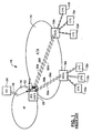
- Fig. 1 is a block diagram schematically illustrating a communications network 10 in which the present invention may be deployed.
- the communications network 10 generally comprises an asynchronous transfer mode (ATM) switching network 14 coupled to an Internet Protocol (IP) network 16 via one or more IP service gateways 28 (IPS GWY).
- IP Internet Protocol
- IPS GWY IP service gateways 28
- the ATM switching network 14 includes a plurality of access modules (AM) 18a and 18b (two are shown in Fig. 1), each of which serves to couple a respective plurality of end-user customer premise equipment (CPE) 12 (each of which may, for example, be a DSL modem connected to a PC).
- AM access modules
- CPE customer premise equipment
- this arrangement permits each CPE 12a-f to obtain high bandwidth access to the IP network 16 using conventional virtual channel (VC) connections 30a-30f mapped through the ATM switching network 14 between one of the access modules 18a,b and the IPS GWY 28.
- VC virtual channel
- a multicast server 24 can be coupled to the IP network 16 in a conventional manner.
- a CPE 12 is thereby enabled to access the multicast server 24 and send a join message via the IPS GWY 28 to the multicast server 24 to receive multicast content sourced from the multicast server 24.
- multicast packets will be routed to the end-user's CPE 12 via the IPS GWY 28 to a multicast tree 26 originating at the multicast server 24, so that the end-user's CPE 12 will be enabled to receive the multicast traffic using IP routing functions.
- the IPS GWY 28 is commonly used as a gateway for the multicast server 24 to route multicast traffic into the ATM switching network 14.
- multicast traffic sourced from the multicast server 24 (the root of the multicast tree) is conveyed to the IPS GWY 28 in a conventional manner, and then conveyed to each recipient of the multicast traffic using virtual channel connections 30a-f mapped through the ATM switching network 14 between the IPS GWY 28 and the respective access modules 18.
- the CPEs 12a-f are connected to the IPS GWY 28 by a plurality of respective VCs 30a-f.
- the VCs 30a-f may be switched virtual circuits (SVCs), or permanent virtual circuits (PVCs), as set up by a service provider.
- SVCs switched virtual circuits
- PVCs permanent virtual circuits
- join message When an end user of a CPE 12a-f sends a join message to join a multicast tree, the join message traverses the corresponding VC 30a-f to the IPS GWY, which performs an IP routing function to merge the multicast content, received from MS 24 through multicast tree 26, into a respective VC 30a-f of the end user.
- end-users at CPEs 12a,c-f are grafted to the multicast tree 26.
- service access trunks (not shown) connecting the respective AMs 18a,b to the ATM switching network 14 are congested by the heavy traffic induced by multiple copies of the bandwidth-intensive multicast content transferred simultaneously over a plurality of VCs supported by the service access links 30a-f.
- Fig. 2 is a message flow diagram illustrating the principal messages exchanged during the set up of a connection between an end-user's CPE 12a and the multicast tree in accordance with the prior art.
- an end-user at CPE 12a sends a join request (step 50) to the IPS GWY 28 to be joined to a multicast tree 26 (Fig. 1) that originates from the multicast server 24 in IP network 16.
- the IPS GWY 28 will accordingly join the multicast tree using a standard IP multicast protocol.
- the IPS GWY 28 performs an IP routing function (step 52) which merges the multicast content with other IP traffic on the VC 30a (Fig. 1) assigned to CPE 12a.
- the VC 30a transports the multicast content through the ATM switching network 14 and the service access trunk (not shown) that connects the AM 18a to the ATM switching network 14 as shown in step 54 of Fig. 2.
- regular join messages in accordance with IP multicast protocol which is well know in the art, are sent on a periodic basis at steps 56, 58 from the CPE 12a to the IPS GWY 28.
- join messages are no longer sent.
- a time-out trigger associated with the VC 30a alerts the IPS GWY 28 (step 60) that the CPE 12a is no longer sending join messages.
- the IPS GWY 28 therefore terminates the IP multicast packet merge in step 62.
- Other IP packets (step 64) continue to be transferred through the VC 30a, as it was prior to the IP multicast packet merge occurring.
- other methods may be used for disconnect, such as an explicit disconnect message sent from the end-user CPE.
- Fig. 3 shows a system in accordance with the invention.
- Each of the components of the network 10 are identical to those shown in Fig. 1 with the exception that the IPS GWY 28 and the Access Modules 18a, 18b are modified to provide multicast service in accordance with the invention.
- No modification is required at the multicast server 24 or the CPE 12a-f.
- no modification is required within the ATM switching network 14 to implement the methods in accordance with the invention.
- the end-user VCs 30a-30f which provide a connection between the CPEs 12a-12f and the IPS GWY 28 remain, in order to transfer IP packets between the IPS GWY 28 and the respective CPEs 12a-f.
- the IPS GWY 28 is modified so that it no longer performs an IP packet merge on receipt of a join request from one of the CPEs 12a-f. Instead, the multicast packets are sent to the respective access modules 18a, b using separate virtual connections 38a, b, and an ATM VC merge 40a, 40b is performed by the respective access modules 18a,b. Consequently, only one copy of the multicast packets traverses the ATM switching network 14 for each access module serving CPEs connected to the multicast tree, regardless of the number of CPEs joined to the multicast tree at each AM 18a, b.
- Congestion in the service access trunks (not shown) connecting each access module 18a,b to the ATM switching network 14 is therefore significantly reduced when two or more CPEs connected to the same AM 18a,b join the same multicast session.
- a quality of service (QoS) guarantee associated with the VCs 38a, b ensures that the multicast traffic is transferred across the ATM network at a QoS that is generally higher than the QoS associated with the end-user VCs 30a-30f. Consequently, a higher quality service is delivered to the end-user.
- QoS quality of service
- the VC merge performed by the access module 18a, b may respect the QoS associated with the respective packet streams so that the quality of service delivery is further improved.
- Fig. 4 more clearly illustrates the method in accordance with the invention by schematically showing principal messages exchanged to join a sink node (CPEs 12d, 12f) to the multicast tree 26 (Fig. 3).
- CPEs 12d, 12f sink node
- a join request message is sent from CPE 12d to an ingress node (IPS GWY 28) in step 100.
- the IPS GWY 28 responds to the join request by referring to an internal table 42 (Fig. 3) that relates the VC on which the join request was received to a network address of the access module 18b.
- the IPS GWY 28 therefore formulates a signaling message in accordance with the invention and sends the signaling message to instruct the access module 18b to connect the CPE 12d to the multicast session.
- a multicast service access point (multicast SAP) 29 may be associated with the IPS GWY 28 to handle the actual multicast packet delivery.
- the multicast SAP 29 may be an integral part of the IPS GWY 28, or a separate network element controlled by one or more IPS GWY 28.
- each multicast session is assigned a unique session identifier that enables the IPS GWY 28 to identify the multicast session to the access module 18b by including the session identifier in the signaling message.
- the access module 18b determines in step 104 whether it is branched to the multicast session. In this example, the access module 18b is not branched to the multicast session. The access module 18b therefore sends an SVC setup message in step 106 to the IPS GWY to request the setup of an SVC by the IPS GWY 28 in order to supply the multicast packets.
- multicast packets begin flowing to the access module 18b in step 110.
- PVCs permanent virtual circuits
- the IPS GWY 28 signals the MS 24 (Fig. 3) to request connection of the multicast SAP 29 to the multicast tree in order to receive the multicast packets which are sent in step 110 to the access module 18b.
- the access module 18b grafts a leaf to the multicast tree in step 112, to add the CPE 12d to the multicast tree.
- the access module 18b performs a VC merge to merge the multicast traffic with other traffic sent over the VC that serves the CPE 12d.
- the VC merge is a packet merge, and the merge may respect the respective QoS levels of the multicast packets and other IP traffic streams.
- the multicast and other IP traffic are delivered to the CPE 12d in step 116.
- CPE 12d may send join messages at regular intervals to the IPS GWY 28, as is well known in the protocol in accordance with the prior art. In accordance with the invention, this protocol remains unchanged. Consequently, CPE 12d can send join messages at regular intervals (steps 118, 126, 134) to the IPS GWY 28.
- the CPE 12f sends a join request message to the IPS GWY 28 requesting a join to the same multicast tree.
- the IPS GWY 28 responds by sending a signaling message in step 122 to the access module 18b requesting that the access module 18b join the CPE 12f to the multicast session.
- the access module 18b consults internal tables and determines that it already terminates a branch of the multicast tree. It therefore creates a leaf for the CPE 12f in step 124 and performs a VC merge in step 128 to add the multicast packet traffic to other IP traffic travelling over the VC that serves the CPE 12f (step 130).
- CPE 12f may send join messages (132, 146) at regular intervals to the IPS GWY 28 to maintain its connection to the multicast tree.
- CPE 12d ceases sending join messages after the join message sent in step 134.
- a time-out is triggered (step 136) which prompts the IPS GWY 28 to disconnect CPE 12d from the multicast tree.
- the IPS GWY 28 therefore sends a disconnect message over a signaling channel in step 138 to the access module 18b.
- the access module 18b removes the leaf that joins CPE 12d to the multicast tree (step 140) and ends the VC merge (step 142).
- step 144 the CPE 12f sends a last join message to the IPS GWY 28.
- the cessation of transmission of join messages to the IPS GWY 28 causes a time-out to be triggered in step 148.
- the IPS GWY 28 sends a disconnect message to the access module 18b requesting that the CPE 12f be disconnected from the multicast tree (step 150).
- the access module 18b removes the leaf from the multicast tree and ends the VC merge in step 154.
- the access module Since the access module no longer requires the multicast packet traffic, if the multicast packets are carried on an SVC, it sends an SVC release in step 156 to the ATM network requesting that the SVC 38b that carries the multicast traffic to the access module 18b be released. In response, the IPS GWY 28 instructs the multicast SAP 29 to cease transmitting the multicast packets over the SVC, the SVC is released and a release acknowledgement is transmitted (step 158) back to the access module 18b. It will be understood that the method of disconnecting from a multicast tree described above is only exemplary of protocols used for that purpose. Some protocols support explicit disconnect messages, while others support discrete headend queries, etc.
- the present invention provides a method and apparatus for grafting connections to a multicast tree which substantially eliminate redundant duplication of multicast traffic within the ATM switching network 4. Furthermore, since the multicast packet traffic traverses the ATM switching network via a VC that is independent of the end-user VC, quality of service (QoS) provisions in the ATM network govern delivery of the multicast packet traffic to the DSLAM. At the DSLAM, the multicast packet traffic, which has an associated QoS, is merged with other IP traffic for the end-user, which normally has a different QoS. Thus, the end-user is provided with a better service, without being aware of QoS considerations in the transport network.
- QoS quality of service
Abstract
Description
- The present invention relates to Internet Protocol (IP) multicast services, and in particular to a method and system for grafting connections to an IP multicast tree set up through an Asynchronous Transfer Mode (ATM) switching network.
- The evolution of communications networks (e.g. the Internet) has been accompanied by increasing demand by users for delivery of multicast services over such networks. Multicast services distribute, for example, news, entertainment or educational content, which is transported over the network from a single source node to a plurality of sink nodes. The source node is typically a multicast server, such as an Internet Protocol (IP) server connected to an IP data network that outputs the multicast content. The sink node is typically an end-user's communication device such as a personal computer (PC) connected to the network via a modem.
- For high bandwidth applications, the use of Digital Subscriber Loop (DSL) technology, cable modems, satellite systems, and the like, are becoming increasingly popular as a means of coupling customer-premise equipment (CPE), such as personal computers (PCs) or Local Area Network (LAN) servers to the communications network. Many of these access technologies are based primarily on the use of an ATM switching network for data transport, which facilitates high bandwidth data transfer, while simplifying network provisioning and management. Multicast data from the source node is typically routed to the ATM switching network through an Internet Protocol (IP) service gateway (IPS GWY)). Each sink node (i.e. CPE) is normally connected to the ATM switching network via an access module (e.g. a Digital Subscriber Line Access Multiplexer (DSLAM); a cable headend; a wireless headend; a satellite base station; an optical line termination; or customer premise equipment).
- When an end-user wishes to join a multicast session, a join request message originating at the end-user's CPE is forwarded to the IPS GWY. Upon receipt of the join request message, the IPS GWY joins the sink node directly to the multicast tree if the IPS GWY is already grafted to the multicast tree. If not, the IPS GWY establishes a connection with the multicast source node to establish a branch on the multicast tree. The IPS GWY joins the sink node to the multicast tree by performing standard IP routing to route the multicast traffic into a virtual channel used to provide DSL service to the end-user's CPE. Once the multicast source has been joined, high bandwidth multicast content originating at the source node is routed through the access module to the end-user's CPE over the end-user's channel, a switched virtual circuit (SVC) or a permanent virtual circuit (PVC), for example. This approach avoids supporting any IP protocols in nodes in the ATM switching network. However, a limitation of this approach is that it results in redundant duplication of multicast traffic within the ATM switching network.
- In particular, two or more participating CPEs served by the same access module results in multiple copies of the multicast traffic being routed through the ATM switching network between the IPS GWY and the access module. This can degrade performance on access feeder trunks between the access module and the ATM switching network, due to bandwidth exhaustion. Furthermore, since the multicast packets traverse the ATM switching network via virtual channels (VCs) serving the respective CPEs, the quality of service (QoS) associated with the respective VCs is transferred to the multicast packets. This may affect the rate of transfer of the multicast packets across the ATM switching network and degrade multicast performance.
- Accordingly, a way of grafting end-users to a multicast tree that minimizes duplication of traffic within the ATM switching network while preserving associated QoS is highly desirable.
- The invention provides a method of setting up a connection through an Asynchronous Transfer Mode (ATM) switching network between a sink node and a multicast tree, the multicast tree being coupled to the ATM switching network via an ingress node, and the sink node being coupled to the ATM switching network via an access module, the method comprising:
- identifying the access module through which the sink node is coupled to the ATM switching network;
- sending a message to the access module requesting that the sink node be connected to the multicast tree;
- grafting a leaf to the multicast tree at the access module to connect the sink node to the multicast tree; and
- merging multicast packets into an existing service connection for the sink node.
-
- The access module and the sink node are identified by the ingress node that examines a virtual channel (VC) on which a join request message was received from the sink node to identify the access module and the sink node. The leaf to the multicast tree at the access module is grafted to the multicast tree by performing a virtual channel (VC) merge, to merge the multicast packets with other IP packet traffic for the sink node. The VC merge is performed by the access module. If the access module is not branched to the multicast tree, the access module sends a signaling message to the ingress node requesting a connection with the ingress node in order to receive copies of the multicast packets.
- The invention also provides a system for setting up a connection through an Asynchronous Transfer Mode (ATM) switching network between a sink node and a multicast tree, the multicast tree being coupled to the ATM switching network via an ingress node, and the sink node being coupled to the ATM switching network via a respective one of a plurality of access modules, the system comprising:
- means for identifying an access module through which the sink node is coupled to the ATM switching network;
- means for determining whether the identified access module is already part of the multicast tree;
- means for grafting a leaf to the multicast tree at the identified access module when the identified access module is connected to the multicast tree; and
- means for merging multicast packets with other IP traffic on an existing service channel for the sink node.
-
- The ingress node is, for example, an Internet Protocol Service Gateway (IPS GWY), and the access module is, for example, a Digital Subscriber Line Access Multiplexer (DSLAM); a cable headend; a wireless headend; a satellite base station; and optical line termination; or, an ATM side of a customer premise equipment.
- The means for identifying the access module comprises a table for relating a virtual channel on which the join request was received from the sink node with an address of an access module that supports the virtual channel. The access module receives a connection instruction from the ingress node requesting connection of the sink node to the multicast tree. The connection request message includes a multicast session identifier uniquely identifying the multicast session. The multicast session identifier is used at the access module to determine whether multicast traffic associated with the multicast session identifier is being received at the access module. The sink node is grafted to the multicast tree at the access module by performing a VC merge at the access module. Consequently, only one copy of the multicast traffic traverses the ATM switching network between the ingress node and the access module while a plurality of sink nodes may be joined to the multicast tree at the access module.
- The invention further provides an IPS GWY that is adapted to reduced the duplication of multicast traffic through the ATM switching network. The IPS GWY is adapted to identify an access module through which the sink node that requested a join to the multicast tree is coupled to the ATM switching network. The IPS GWY is further adapted to request the access module to join the sink node to the multicast tree, and to set up a virtual connection with the access module to connect the access module to the multicast tree, if required. The IPS GWY identifies the access module using a table that relates a virtual channel (VC) on which a join request was received from the sink node with a network address of the access module.
- The invention also provides an access module for an ATM switching network adapted to enable the grafting of a connection between a sink node and a multicast tree. The access module is coupled to the ATM switching network and the sink node. The access module comprises means for grafting a leaf to the multicast tree to connect the sink node to the multicast tree and means for performing a VC merge to merge multicast packets with other IP traffic being sent to and from the sink node. The access module only grafts a leaf to the multicast tree and performs a VC merge on receipt of a request message from a gateway node through which the multicast tree enters the ATM switching network. The signaling message requests that the access module connect the sink node to the multicast tree. On receipt of the request, the access module performs a VC merge to merge the multicast packets with other IP traffic for the sink node.
- The invention therefore significantly reduces congestion in an ATM switching network that provides multicast services without impacting existing Internet protocol standards. The invention also supports the ability to combine multiple connections together, each of the connections having a different quality of services, into a single ATM connection as a service for the end-user without the end-user being aware of the quality of service considerations at work in the network. Therefore, a single copy of an IP multicast service is shared among users. The access module, however, requires no knowledge of the IP protocol used for delivering the multicast traffic to the end-users. Thus, the methods and apparatus in accordance with the invention significantly reduce duplication of traffic through the ATM network while ensuring high quality service without changing customer premises equipment.
- The invention provides a method and apparatus of grafting end-users to a multicast tree in which duplication of multicast traffic within the ATM switching network is reduced. The invention also provides a method of providing multicast services to DSL subscribers that reduces congestion on an access feeder trunk between an access module and an ATM transport network.
- Examples of the invention will now be described in detail with reference to the accompanying drawings, in which:
- Fig. 1. is a block diagram schematically illustrating respective multicast trees mapped through an ATM network in accordance with the prior art;
- Fig. 2 is a message flow diagram schematically illustrating principal messages exchanged between the IPS GWY and a CPE shown in Fig. 1, to join the CPE to a multicast tree in accordance with prior art procedures currently used;
- Fig. 3 is a schematic diagram of multicast trees mapped through an ATM switching network in accordance with the invention; and
- Fig. 4 is a message flow diagram schematically illustrating the principal messages exchanged between the IPS GWY and two CPEs shown in Fig. 3, to join the CPEs to a multicast tree in accordance with the present invention.
-
- It will be noted that throughout the appended drawings, like features are identified by like reference numerals.
- The present invention provides a method and apparatus for grafting connections to a multicast tree through an ATM switching network. Fig. 1 is a block diagram schematically illustrating a
communications network 10 in which the present invention may be deployed. Thecommunications network 10 generally comprises an asynchronous transfer mode (ATM) switchingnetwork 14 coupled to an Internet Protocol (IP)network 16 via one or more IP service gateways 28 (IPS GWY). TheATM switching network 14 includes a plurality of access modules (AM) 18a and 18b (two are shown in Fig. 1), each of which serves to couple a respective plurality of end-user customer premise equipment (CPE) 12 (each of which may, for example, be a DSL modem connected to a PC). As is known in the art, this arrangement permits eachCPE 12a-f to obtain high bandwidth access to theIP network 16 using conventional virtual channel (VC)connections 30a-30f mapped through theATM switching network 14 between one of theaccess modules 18a,b and theIPS GWY 28. - As shown in Fig. 1, a
multicast server 24 can be coupled to theIP network 16 in a conventional manner. A CPE 12 is thereby enabled to access themulticast server 24 and send a join message via theIPS GWY 28 to themulticast server 24 to receive multicast content sourced from themulticast server 24. In response to the join message, multicast packets will be routed to the end-user's CPE 12 via theIPS GWY 28 to amulticast tree 26 originating at themulticast server 24, so that the end-user's CPE 12 will be enabled to receive the multicast traffic using IP routing functions. As illustrated in Fig. 1, theIPS GWY 28 is commonly used as a gateway for themulticast server 24 to route multicast traffic into theATM switching network 14. Thus multicast traffic sourced from the multicast server 24 (the root of the multicast tree) is conveyed to theIPS GWY 28 in a conventional manner, and then conveyed to each recipient of the multicast traffic usingvirtual channel connections 30a-f mapped through theATM switching network 14 between theIPS GWY 28 and the respective access modules 18. As is well understood by those skilled in the art, theCPEs 12a-f are connected to theIPS GWY 28 by a plurality ofrespective VCs 30a-f. The VCs 30a-f may be switched virtual circuits (SVCs), or permanent virtual circuits (PVCs), as set up by a service provider. Each VC connects an ATM side of the CPE with theIPS GWY 28. When an end user of aCPE 12a-f sends a join message to join a multicast tree, the join message traverses the correspondingVC 30a-f to the IPS GWY, which performs an IP routing function to merge the multicast content, received fromMS 24 throughmulticast tree 26, into arespective VC 30a-f of the end user. As shown in Fig. 1, end-users atCPEs 12a,c-f are grafted to themulticast tree 26. Subsequently, service access trunks (not shown) connecting therespective AMs 18a,b to theATM switching network 14 are congested by the heavy traffic induced by multiple copies of the bandwidth-intensive multicast content transferred simultaneously over a plurality of VCs supported by theservice access links 30a-f. - Fig. 2 is a message flow diagram illustrating the principal messages exchanged during the set up of a connection between an end-user's
CPE 12a and the multicast tree in accordance with the prior art. As shown in Fig. 2, an end-user atCPE 12a sends a join request (step 50) to theIPS GWY 28 to be joined to a multicast tree 26 (Fig. 1) that originates from themulticast server 24 inIP network 16. TheIPS GWY 28 will accordingly join the multicast tree using a standard IP multicast protocol. On receipt of the join request atstep 50, theIPS GWY 28 performs an IP routing function (step 52) which merges the multicast content with other IP traffic on theVC 30a (Fig. 1) assigned toCPE 12a. As a consequence, theVC 30a transports the multicast content through theATM switching network 14 and the service access trunk (not shown) that connects theAM 18a to theATM switching network 14 as shown instep 54 of Fig. 2. After theCPE 12a is connected to the multicast tree, regular join messages, in accordance with IP multicast protocol which is well know in the art, are sent on a periodic basis atsteps CPE 12a to theIPS GWY 28. When the end-user atCPE 12a wishes to disconnect from the multicast server, in accordance with one IP multicast protocol, join messages are no longer sent. A time-out trigger associated with theVC 30a alerts the IPS GWY 28 (step 60) that theCPE 12a is no longer sending join messages. TheIPS GWY 28 therefore terminates the IP multicast packet merge instep 62. Other IP packets (step 64) continue to be transferred through theVC 30a, as it was prior to the IP multicast packet merge occurring. As is known in the art, other methods may be used for disconnect, such as an explicit disconnect message sent from the end-user CPE. - Fig. 3 shows a system in accordance with the invention. Each of the components of the
network 10 are identical to those shown in Fig. 1 with the exception that theIPS GWY 28 and theAccess Modules multicast server 24 or theCPE 12a-f. Furthermore, no modification is required within theATM switching network 14 to implement the methods in accordance with the invention. As may be seen in Fig. 3, the end-user VCs 30a-30f which provide a connection between theCPEs 12a-12f and theIPS GWY 28 remain, in order to transfer IP packets between theIPS GWY 28 and therespective CPEs 12a-f. However, theIPS GWY 28 is modified so that it no longer performs an IP packet merge on receipt of a join request from one of theCPEs 12a-f. Instead, the multicast packets are sent to therespective access modules 18a, b using separatevirtual connections 38a, b, and anATM VC merge respective access modules 18a,b. Consequently, only one copy of the multicast packets traverses theATM switching network 14 for each access module serving CPEs connected to the multicast tree, regardless of the number of CPEs joined to the multicast tree at eachAM 18a, b. Congestion in the service access trunks (not shown) connecting eachaccess module 18a,b to theATM switching network 14 is therefore significantly reduced when two or more CPEs connected to thesame AM 18a,b join the same multicast session. Furthermore, a quality of service (QoS) guarantee associated with the VCs 38a, b ensures that the multicast traffic is transferred across the ATM network at a QoS that is generally higher than the QoS associated with the end-user VCs 30a-30f. Consequently, a higher quality service is delivered to the end-user. It should also be noted that the VC merge performed by theaccess module 18a, b may respect the QoS associated with the respective packet streams so that the quality of service delivery is further improved. - Fig. 4 more clearly illustrates the method in accordance with the invention by schematically showing principal messages exchanged to join a sink node (
CPEs CPE 12d to an ingress node (IPS GWY 28) instep 100. TheIPS GWY 28 responds to the join request by referring to an internal table 42 (Fig. 3) that relates the VC on which the join request was received to a network address of theaccess module 18b. - The
IPS GWY 28 therefore formulates a signaling message in accordance with the invention and sends the signaling message to instruct theaccess module 18b to connect theCPE 12d to the multicast session. As shown in Fig. 4, a multicast service access point (multicast SAP) 29 may be associated with theIPS GWY 28 to handle the actual multicast packet delivery. Themulticast SAP 29 may be an integral part of theIPS GWY 28, or a separate network element controlled by one ormore IPS GWY 28. - As is well known in the art, each multicast session is assigned a unique session identifier that enables the
IPS GWY 28 to identify the multicast session to theaccess module 18b by including the session identifier in the signaling message. On receipt of the signaling message sent instep 102, theaccess module 18b determines instep 104 whether it is branched to the multicast session. In this example, theaccess module 18b is not branched to the multicast session. Theaccess module 18b therefore sends an SVC setup message instep 106 to the IPS GWY to request the setup of an SVC by theIPS GWY 28 in order to supply the multicast packets. Upon connecting to the multicast ATM SAP, multicast packets begin flowing to theaccess module 18b instep 110. It should be understood that the illustrated method of connecting theaccess module 18b to the multicast tree is only one of several methods that can be used. It should also be understood that instead of ATM SVCs, permanent virtual circuits (PVCs) may be used for multicast packet delivery to theaccess module 18b, in which case theaccess module 18b could attach a leaf to a pre-provisioned PVC when access to the multicast packets is required. - As will be understood by persons skilled in the art, if the
multicast SAP 29 is not already connected to a branch of the multicast tree 26 (Fig. 3), theIPS GWY 28 signals the MS 24 (Fig. 3) to request connection of themulticast SAP 29 to the multicast tree in order to receive the multicast packets which are sent instep 110 to theaccess module 18b. On receipt of the multicast packets, theaccess module 18b grafts a leaf to the multicast tree instep 112, to add theCPE 12d to the multicast tree. Instep 114, theaccess module 18b performs a VC merge to merge the multicast traffic with other traffic sent over the VC that serves theCPE 12d. As will be understood by persons skilled in the art, the VC merge is a packet merge, and the merge may respect the respective QoS levels of the multicast packets and other IP traffic streams. Thus, the multicast and other IP traffic are delivered to theCPE 12d instep 116. In order to remain a part of the multicast tree,CPE 12d may send join messages at regular intervals to theIPS GWY 28, as is well known in the protocol in accordance with the prior art. In accordance with the invention, this protocol remains unchanged. Consequently,CPE 12d can send join messages at regular intervals (steps IPS GWY 28. - In
step 120, theCPE 12f sends a join request message to theIPS GWY 28 requesting a join to the same multicast tree. TheIPS GWY 28 responds by sending a signaling message instep 122 to theaccess module 18b requesting that theaccess module 18b join theCPE 12f to the multicast session. On receipt of the signaling message, theaccess module 18b consults internal tables and determines that it already terminates a branch of the multicast tree. It therefore creates a leaf for theCPE 12f instep 124 and performs a VC merge instep 128 to add the multicast packet traffic to other IP traffic travelling over the VC that serves theCPE 12f (step 130). Thereafter,CPE 12f may send join messages (132, 146) at regular intervals to theIPS GWY 28 to maintain its connection to the multicast tree. In the meantime,CPE 12d ceases sending join messages after the join message sent instep 134. After a given time interval, a time-out is triggered (step 136) which prompts theIPS GWY 28 to disconnectCPE 12d from the multicast tree. TheIPS GWY 28 therefore sends a disconnect message over a signaling channel instep 138 to theaccess module 18b. On receipt of the signaling message, theaccess module 18b removes the leaf that joinsCPE 12d to the multicast tree (step 140) and ends the VC merge (step 142). Thereafter, other IP traffic is carried over the VC that serves theCPE 12d (step 144). Instep 146, theCPE 12f sends a last join message to theIPS GWY 28. In the manner described, the cessation of transmission of join messages to theIPS GWY 28 causes a time-out to be triggered instep 148. When the time-out is triggered, theIPS GWY 28 sends a disconnect message to theaccess module 18b requesting that theCPE 12f be disconnected from the multicast tree (step 150). Instep 152, theaccess module 18b removes the leaf from the multicast tree and ends the VC merge instep 154. Since the access module no longer requires the multicast packet traffic, if the multicast packets are carried on an SVC, it sends an SVC release instep 156 to the ATM network requesting that theSVC 38b that carries the multicast traffic to theaccess module 18b be released. In response, theIPS GWY 28 instructs themulticast SAP 29 to cease transmitting the multicast packets over the SVC, the SVC is released and a release acknowledgement is transmitted (step 158) back to theaccess module 18b. It will be understood that the method of disconnecting from a multicast tree described above is only exemplary of protocols used for that purpose. Some protocols support explicit disconnect messages, while others support discrete headend queries, etc. - Thus, it will be seen that the present invention provides a method and apparatus for grafting connections to a multicast tree which substantially eliminate redundant duplication of multicast traffic within the ATM switching network 4. Furthermore, since the multicast packet traffic traverses the ATM switching network via a VC that is independent of the end-user VC, quality of service (QoS) provisions in the ATM network govern delivery of the multicast packet traffic to the DSLAM. At the DSLAM, the multicast packet traffic, which has an associated QoS, is merged with other IP traffic for the end-user, which normally has a different QoS. Thus, the end-user is provided with a better service, without being aware of QoS considerations in the transport network.
- The embodiment(s) of the invention described above is(are) intended to be exemplary only. The scope of the invention is therefore intended to be limited solely by the scope of the appended claims.
Claims (24)
- A method of setting up a connection through an Asynchronous Transfer Mode (ATM) switching network between a sink node and a multicast tree, the multicast tree being coupled to the ATM switching network via an ingress node, and the sink node being coupled to the ATM switching network via an access module, CHARACTERIZED by:identifying the access module through which the sink node is coupled to the ATM switching network;sending a message to the access module requesting that the sink node be connected to the multicast tree;grafting a leaf to the multicast tree at the access module to connect the sink node to the multicast tree; andmerging multicast packets into an existing service connection for the sink node.
- A method as claimed in claim 1, wherein the step of identifying is performed by the ingress node, which is a service gateway to an Internet Protocol (IP) network, and an associated multicast service access point.
- A method as claimed in claim 1 or 2, wherein the step of identifying comprises a step of examining a virtual channel (VC) on which a join request message was received from the sink node to identify the access module and the sink node.
- A method as claimed in claim any preceding claim, wherein the access module is one of a digital subscriber line access multiplexer (DSLAM); cable headend; wireless headend; satellite base station; ATM side of customer premise equipment; and optical line termination.
- A method as claimed in any preceding claim, wherein the step of merging the multicast packets into the existing service connection further comprises a step of performing a virtual channel (VC) merge, to merge the multicast packets with other IP packet traffic for the sink node.
- A method as claimed in claim 5, wherein the step of performing the VC merge is performed by the access module.
- A method as claimed in any preceding claim, wherein if the identified access module is not branched to the multicast tree, the method further comprises a step of connecting the access module to the multicast tree.
- A method as claimed in claim 7, wherein the step of connecting the access module to the multicast tree comprises steps of:establishing a switched virtual circuit (SVC) connection between the access module and the ingress node through the ATM switching network, if required;grafting a leaf to the multi-cast tree for the sink node; andperforming a VC merge, to merge the multicast packets with other IP packet traffic for the sink node.
- A system for setting up a connection through an Asynchronous Transfer Mode (ATM) switching network between a sink node and a multicast tree, the multicast tree being coupled to the ATM switching network via an ingress node, and the sink node being coupled to the ATM switching network via a respective one of a plurality of access modules, CHARACTERIZED by:means for identifying an access module through which the sink node is coupled to the ATM switching network;means for determining whether the identified access module is already part of the multicast tree;means for grafting a leaf to the multicast tree at the identified access module when the identified access module is connected to the multicast tree; andmeans for merging multicast packets with other IP traffic on an existing service channel for the sink node.
- A system as claimed in claim 9, wherein the ingress node is a Internet Protocol Service Gateway (IPS GWY).
- A system as claimed in claim 9 or 10, wherein the means for identifying the access module and the sink node comprises means for relating a virtual channel (VC) on which a join request is received from the sink node with an access module that supports the virtual channel.
- A system as claimed in any one of claims 9 to 11, wherein the means for determining whether the identified access module is part of the multicast tree comprises:a multicast session identifier sent from the ingress node to the access module, the multicast session identifier uniquely identifying the multicast session; andmeans for using the multicast session identifier at the access module to determine whether multicast traffic associated with the multicast session identifier is being received at the access module.
- A system as claimed in any one of claims 9 to 12, further comprising means for performing a VC merge at the access module.
- A system as claimed in any one of claims 9 to 13, further comprising means for grafting a branch to the multicast tree from the ingress node to the access module, if the access module is not branched to the multicast tree.
- A system as claimed in claim 14, wherein the means for grafting the branch to the multicast tree at the access module comprises:means for establishing a virtual circuit (VC) connection between the ingress node and the access module through the ATM switching network;means for grafting the leaf to the branch of the multicast tree; andmeans for performing a VC merge to merge multicast packets with other IP packets arriving for the sink node.
- A system as claimed in claim 10 wherein the IPS GWY comprises:means for identifying an access module through which a sink node that requested a join to a multicast tree is coupled to the ATM switching network;means for requesting the access module to join the sink node to the multicast tree; andmeans for setting up a virtual connection to the access module to connect the access module to the multicast tree.
- The system as claimed in claim 16, wherein the means for identifying the access module and the sink node comprises a table that relates a virtual channel (VC) on which a join request was received with a network address of the access module and the sink node.
- The system as claimed in claim 16 or 17, wherein the means for requesting the access module to join the sink node to the multicast tree comprises means for formulating a signaling message to request the join and for sending the signaling message to the access module.
- The system as claimed in any one of claims 16 to 18, wherein the IPS GWY controls an associated multicast service access point (multicast SAP) that supplies multicast packets to the access module.
- The system as claimed in claim 19 wherein the multicast SAP is co-located with the IPS GWY.
- The system as claimed in claims 19 or 20 wherein the multicast SAP is remote from the IPS GWY and controlled by at least one IPS GWY.
- The system as claimed in any one of claims 9 to 21, wherein the access module comprises any one of a digital subscriber line access multiplexer (DSLAM); cable headend; wireless headend; satellite base station; ATM side of customer premise equipment; and optical line termination.
- The system as claimed in any one of claims 9 to 22, wherein the means for grafting comprises:means for receiving a signaling message from an ingress node through which the sink node internet protocol (IP) virtual circuit (VC) enters the ATM switching network, the signaling message requesting that the access module connect the sink node to the multicast tree; andmeans for performing a virtual channel (VC) merge to merge the multicast packets with other IP traffic for the sink node.
- The system as claimed in claim 23, wherein the access module further comprises means for receiving a further signaling message from the ingress node, the further signaling message instructing that the sink node be disconnected from the multicast tree.
Applications Claiming Priority (4)
| Application Number | Priority Date | Filing Date | Title |
|---|---|---|---|
| US18845900P | 2000-03-10 | 2000-03-10 | |
| US188459P | 2000-03-10 | ||
| US09/648,610 US6931005B1 (en) | 2000-03-10 | 2000-08-28 | IP multicast services over ATM multicast |
| US648610 | 2000-08-28 |
Publications (2)
| Publication Number | Publication Date |
|---|---|
| EP1133117A2 true EP1133117A2 (en) | 2001-09-12 |
| EP1133117A3 EP1133117A3 (en) | 2003-05-28 |
Family
ID=26884091
Family Applications (1)
| Application Number | Title | Priority Date | Filing Date |
|---|---|---|---|
| EP01302197A Withdrawn EP1133117A3 (en) | 2000-03-10 | 2001-03-09 | IP multicast services over an ATM network |
Country Status (3)
| Country | Link |
|---|---|
| US (1) | US6931005B1 (en) |
| EP (1) | EP1133117A3 (en) |
| CA (1) | CA2339721A1 (en) |
Cited By (2)
| Publication number | Priority date | Publication date | Assignee | Title |
|---|---|---|---|---|
| EP1343278A1 (en) * | 2002-03-05 | 2003-09-10 | Alcatel | Facilitating IP-Based multicasting control connections over ATM |
| WO2006049821A2 (en) | 2004-11-01 | 2006-05-11 | Cisco Technology, Inc. | A method for multicast load balancing in wireless lans |
Families Citing this family (21)
| Publication number | Priority date | Publication date | Assignee | Title |
|---|---|---|---|---|
| BR0111453A (en) * | 2000-06-08 | 2003-06-24 | Thomson Licensing Sa | Atm multicast for releasing information over a network |
| AU2002239254A1 (en) * | 2000-11-17 | 2002-06-03 | Starguide Digital Networks, Inc. | Method and apparatus for injection of ip multicast content into an atm dsl network |
| EP1340404A1 (en) * | 2000-12-04 | 2003-09-03 | Siemens Aktiengesellschaft | Method for multicasting information via at least one communications network |
| JP2004530320A (en) * | 2001-02-19 | 2004-09-30 | ブリティッシュ・テレコミュニケーションズ・パブリック・リミテッド・カンパニー | Forwarding tree generation in communication networks |
| WO2002080456A1 (en) * | 2001-03-30 | 2002-10-10 | Egc & C Co., Ltd. | Method of intermediating multicasting signal for multicasting embodiment |
| WO2002098099A1 (en) * | 2001-05-28 | 2002-12-05 | Nokia Corporation | Charging in telecommunications network |
| US7065577B1 (en) * | 2002-03-27 | 2006-06-20 | Alcatel | Facilitating IP-based multicasting control connections |
| KR100934279B1 (en) * | 2003-10-08 | 2009-12-28 | 삼성전자주식회사 | Hybrid base station device in mobile communication system |
| US7821948B2 (en) * | 2004-05-27 | 2010-10-26 | Alcatel Lucent | Network management system and method provisioning OAM support for multicast communications sessions |
| US7489684B2 (en) * | 2004-12-08 | 2009-02-10 | Alcatel Lucent | Access network architecture for multicasting using xDSL and IGMP |
| ATE413752T1 (en) * | 2005-08-29 | 2008-11-15 | Alcatel Lucent | ACCESS MULTIPLEXER |
| CN100563203C (en) * | 2005-11-11 | 2009-11-25 | 华为技术有限公司 | The method that multicast tree leaf node network element signal transmits in the communication network |
| US8018964B2 (en) * | 2005-12-16 | 2011-09-13 | Cisco Technology, Inc. | Multicast operations using prioritized state information |
| CN101179485B (en) * | 2006-11-10 | 2011-10-26 | 中兴通讯股份有限公司 | Route selecting method of new adding multicast member |
| US8018933B2 (en) | 2007-06-27 | 2011-09-13 | Microsoft Corporation | Reliable multicast with automatic session startup and client backfil support |
| US8612617B2 (en) * | 2007-06-28 | 2013-12-17 | Microsoft Corporation | Reliable multicast transport protocol |
| US8683065B2 (en) * | 2007-06-29 | 2014-03-25 | Microsoft Corporation | Multicast content provider |
| KR101087142B1 (en) | 2008-12-22 | 2011-11-25 | 한국전자통신연구원 | Apparatus and method for packet multicast |
| US8867539B2 (en) | 2009-09-18 | 2014-10-21 | At&T Intellectual Property I, L.P. | Multicast-unicast protocol converter |
| US8150993B2 (en) | 2009-10-29 | 2012-04-03 | At&T Intellectual Property I, Lp | Synchronization of clients to maximize multicast opportunities |
| US11240099B2 (en) * | 2017-10-05 | 2022-02-01 | Cable Television Laboratories, Inc. | Network grafting |
Citations (2)
| Publication number | Priority date | Publication date | Assignee | Title |
|---|---|---|---|---|
| EP0818903A2 (en) * | 1996-07-11 | 1998-01-14 | Kabushiki Kaisha Toshiba | Packet multicasting in network for providing various QOS |
| EP0854618A2 (en) * | 1997-01-17 | 1998-07-22 | Lucent Technologies Inc. | A dynamic distributed multicast routing protocol |
Family Cites Families (9)
| Publication number | Priority date | Publication date | Assignee | Title |
|---|---|---|---|---|
| US5331637A (en) * | 1993-07-30 | 1994-07-19 | Bell Communications Research, Inc. | Multicast routing using core based trees |
| US5684800A (en) | 1995-11-15 | 1997-11-04 | Cabletron Systems, Inc. | Method for establishing restricted broadcast groups in a switched network |
| US5835723A (en) | 1995-12-28 | 1998-11-10 | Intel Corporation | Dynamic assignment of multicast addresses |
| US5831975A (en) | 1996-04-04 | 1998-11-03 | Lucent Technologies Inc. | System and method for hierarchical multicast routing in ATM networks |
| KR100194608B1 (en) * | 1996-11-20 | 1999-06-15 | 이계철 | Multicast Path Allocation Method in ATM Networks |
| US6078590A (en) * | 1997-07-14 | 2000-06-20 | Cisco Technology, Inc. | Hierarchical routing knowledge for multicast packet routing |
| US6097720A (en) * | 1998-04-07 | 2000-08-01 | 3Com Corporation | Enabling multicast distribution efficiencies in a dialup access environment |
| US6611872B1 (en) * | 1999-01-11 | 2003-08-26 | Fastforward Networks, Inc. | Performing multicast communication in computer networks by using overlay routing |
| US6556544B1 (en) * | 1999-10-22 | 2003-04-29 | Nortel Networks Limited | Method and system for provisioning network resources for dynamic multicast groups |
-
2000
- 2000-08-28 US US09/648,610 patent/US6931005B1/en not_active Expired - Lifetime
-
2001
- 2001-03-08 CA CA002339721A patent/CA2339721A1/en not_active Abandoned
- 2001-03-09 EP EP01302197A patent/EP1133117A3/en not_active Withdrawn
Patent Citations (2)
| Publication number | Priority date | Publication date | Assignee | Title |
|---|---|---|---|---|
| EP0818903A2 (en) * | 1996-07-11 | 1998-01-14 | Kabushiki Kaisha Toshiba | Packet multicasting in network for providing various QOS |
| EP0854618A2 (en) * | 1997-01-17 | 1998-07-22 | Lucent Technologies Inc. | A dynamic distributed multicast routing protocol |
Non-Patent Citations (1)
| Title |
|---|
| ARMITAGE G J: "MULTICAST AND MULTIPROTOCOL SUPPORT FOR ATM BASED INTERNETS" COMPUTER COMMUNICATIONS REVIEW, ASSOCIATION FOR COMPUTING MACHINERY. NEW YORK, US, vol. 25, no. 2, 1 April 1995 (1995-04-01), pages 34-46, XP000670497 ISSN: 0146-4833 * |
Cited By (6)
| Publication number | Priority date | Publication date | Assignee | Title |
|---|---|---|---|---|
| EP1343278A1 (en) * | 2002-03-05 | 2003-09-10 | Alcatel | Facilitating IP-Based multicasting control connections over ATM |
| US7254135B2 (en) | 2002-03-05 | 2007-08-07 | Alcatel | Facilitating IP-based multicasting control connections |
| WO2006049821A2 (en) | 2004-11-01 | 2006-05-11 | Cisco Technology, Inc. | A method for multicast load balancing in wireless lans |
| EP1807955A2 (en) * | 2004-11-01 | 2007-07-18 | Cisco Technology, Inc. | A method for multicast load balancing in wireless lans |
| EP1807955A4 (en) * | 2004-11-01 | 2010-12-08 | Cisco Tech Inc | A method for multicast load balancing in wireless lans |
| US8306027B2 (en) | 2004-11-01 | 2012-11-06 | Cisco Technology, Inc. | Method for multicast load balancing in wireless LANS |
Also Published As
| Publication number | Publication date |
|---|---|
| EP1133117A3 (en) | 2003-05-28 |
| US6931005B1 (en) | 2005-08-16 |
| CA2339721A1 (en) | 2001-09-10 |
Similar Documents
| Publication | Publication Date | Title |
|---|---|---|
| US6931005B1 (en) | IP multicast services over ATM multicast | |
| US6788696B2 (en) | Transparent QoS using VC-merge capable access modules | |
| US6751218B1 (en) | Method and system for ATM-coupled multicast service over IP networks | |
| US8559444B2 (en) | Controlling data link layer elements with network layer elements | |
| US7912056B1 (en) | Dynamic traffic shaping adjustments for distributed multicast replication | |
| US8144721B2 (en) | Ring overlay network dedicated to carry broadcast traffic to DSLAMs | |
| KR100500838B1 (en) | Satellite IP multicasting system and method | |
| US5905726A (en) | Broadband communication system having a virtual circuit space switch | |
| US20060013247A1 (en) | Traffic management for a passive optical network terminal | |
| AU2006203205A1 (en) | An optical access network system and multicast communication method thereof | |
| US7489684B2 (en) | Access network architecture for multicasting using xDSL and IGMP | |
| US8144690B2 (en) | ATM multicasting for delivering information over a network | |
| US6717914B1 (en) | System for probing switched virtual circuits in a connection oriented network | |
| US6885675B1 (en) | Data transport system | |
| CN100459564C (en) | Method & apparatus for providing multicast capability within an ATM network | |
| KR101338035B1 (en) | Method, communication arrangement and communication device for transferring information | |
| Cisco | M | |
| Cisco | M | |
| Cisco | M | |
| US20040213239A1 (en) | Implementation of IP multicast on ATM network with EMCON links | |
| Boecking et al. | BERKOM multimedia transport system | |
| US7636375B2 (en) | Method for multimedia flow transport | |
| KR100564769B1 (en) | Multicast router and ethernet switch for providing broadcast stream | |
| CN100474843C (en) | Method for treating departure of user in multicast service, and network access device thereof | |
| US7383351B1 (en) | Method and apparatus for efficient SPVC destination endpoint address change |
Legal Events
| Date | Code | Title | Description |
|---|---|---|---|
| PUAI | Public reference made under article 153(3) epc to a published international application that has entered the european phase |
Free format text: ORIGINAL CODE: 0009012 |
|
| 17P | Request for examination filed |
Effective date: 20010411 |
|
| AK | Designated contracting states |
Kind code of ref document: A2 Designated state(s): AT BE CH CY DE DK ES FI FR GB GR IE IT LI LU MC NL PT SE TR |
|
| AX | Request for extension of the european patent |
Free format text: AL;LT;LV;MK;RO;SI |
|
| PUAL | Search report despatched |
Free format text: ORIGINAL CODE: 0009013 |
|
| AK | Designated contracting states |
Designated state(s): AT BE CH CY DE DK ES FI FR GB GR IE IT LI LU MC NL PT SE TR |
|
| AX | Request for extension of the european patent |
Extension state: AL LT LV MK RO SI |
|
| RIC1 | Information provided on ipc code assigned before grant |
Ipc: 7H 04Q 11/04 B Ipc: 7H 04L 12/56 A |
|
| RAP1 | Party data changed (applicant data changed or rights of an application transferred) |
Owner name: NORTEL NETWORKS LIMITED |
|
| AKX | Designation fees paid |
Designated state(s): DE FR GB |
|
| STAA | Information on the status of an ep patent application or granted ep patent |
Free format text: STATUS: THE APPLICATION IS DEEMED TO BE WITHDRAWN |
|
| 18D | Application deemed to be withdrawn |
Effective date: 20051001 |