EP1133652B1 - Manifold system of removable components for distribution of fluids - Google Patents
Manifold system of removable components for distribution of fluids Download PDFInfo
- Publication number
- EP1133652B1 EP1133652B1 EP99933722A EP99933722A EP1133652B1 EP 1133652 B1 EP1133652 B1 EP 1133652B1 EP 99933722 A EP99933722 A EP 99933722A EP 99933722 A EP99933722 A EP 99933722A EP 1133652 B1 EP1133652 B1 EP 1133652B1
- Authority
- EP
- European Patent Office
- Prior art keywords
- manifold
- flange
- manifold block
- block
- blocks
- Prior art date
- Legal status (The legal status is an assumption and is not a legal conclusion. Google has not performed a legal analysis and makes no representation as to the accuracy of the status listed.)
- Expired - Lifetime
Links
Images


Classifications
-
- C—CHEMISTRY; METALLURGY
- C23—COATING METALLIC MATERIAL; COATING MATERIAL WITH METALLIC MATERIAL; CHEMICAL SURFACE TREATMENT; DIFFUSION TREATMENT OF METALLIC MATERIAL; COATING BY VACUUM EVAPORATION, BY SPUTTERING, BY ION IMPLANTATION OR BY CHEMICAL VAPOUR DEPOSITION, IN GENERAL; INHIBITING CORROSION OF METALLIC MATERIAL OR INCRUSTATION IN GENERAL
- C23C—COATING METALLIC MATERIAL; COATING MATERIAL WITH METALLIC MATERIAL; SURFACE TREATMENT OF METALLIC MATERIAL BY DIFFUSION INTO THE SURFACE, BY CHEMICAL CONVERSION OR SUBSTITUTION; COATING BY VACUUM EVAPORATION, BY SPUTTERING, BY ION IMPLANTATION OR BY CHEMICAL VAPOUR DEPOSITION, IN GENERAL
- C23C16/00—Chemical coating by decomposition of gaseous compounds, without leaving reaction products of surface material in the coating, i.e. chemical vapour deposition [CVD] processes
- C23C16/44—Chemical coating by decomposition of gaseous compounds, without leaving reaction products of surface material in the coating, i.e. chemical vapour deposition [CVD] processes characterised by the method of coating
- C23C16/455—Chemical coating by decomposition of gaseous compounds, without leaving reaction products of surface material in the coating, i.e. chemical vapour deposition [CVD] processes characterised by the method of coating characterised by the method used for introducing gases into reaction chamber or for modifying gas flows in reaction chamber
- C23C16/45561—Gas plumbing upstream of the reaction chamber
-
- F—MECHANICAL ENGINEERING; LIGHTING; HEATING; WEAPONS; BLASTING
- F16—ENGINEERING ELEMENTS AND UNITS; GENERAL MEASURES FOR PRODUCING AND MAINTAINING EFFECTIVE FUNCTIONING OF MACHINES OR INSTALLATIONS; THERMAL INSULATION IN GENERAL
- F16K—VALVES; TAPS; COCKS; ACTUATING-FLOATS; DEVICES FOR VENTING OR AERATING
- F16K11/00—Multiple-way valves, e.g. mixing valves; Pipe fittings incorporating such valves
- F16K11/10—Multiple-way valves, e.g. mixing valves; Pipe fittings incorporating such valves with two or more closure members not moving as a unit
- F16K11/20—Multiple-way valves, e.g. mixing valves; Pipe fittings incorporating such valves with two or more closure members not moving as a unit operated by separate actuating members
- F16K11/22—Multiple-way valves, e.g. mixing valves; Pipe fittings incorporating such valves with two or more closure members not moving as a unit operated by separate actuating members with an actuating member for each valve, e.g. interconnected to form multiple-way valves
-
- F—MECHANICAL ENGINEERING; LIGHTING; HEATING; WEAPONS; BLASTING
- F16—ENGINEERING ELEMENTS AND UNITS; GENERAL MEASURES FOR PRODUCING AND MAINTAINING EFFECTIVE FUNCTIONING OF MACHINES OR INSTALLATIONS; THERMAL INSULATION IN GENERAL
- F16K—VALVES; TAPS; COCKS; ACTUATING-FLOATS; DEVICES FOR VENTING OR AERATING
- F16K27/00—Construction of housing; Use of materials therefor
- F16K27/003—Housing formed from a plurality of the same valve elements
-
- H—ELECTRICITY
- H01—ELECTRIC ELEMENTS
- H01J—ELECTRIC DISCHARGE TUBES OR DISCHARGE LAMPS
- H01J37/00—Discharge tubes with provision for introducing objects or material to be exposed to the discharge, e.g. for the purpose of examination or processing thereof
- H01J37/32—Gas-filled discharge tubes
- H01J37/32431—Constructional details of the reactor
- H01J37/3244—Gas supply means
-
- H—ELECTRICITY
- H01—ELECTRIC ELEMENTS
- H01L—SEMICONDUCTOR DEVICES NOT COVERED BY CLASS H10
- H01L21/00—Processes or apparatus adapted for the manufacture or treatment of semiconductor or solid state devices or of parts thereof
- H01L21/67—Apparatus specially adapted for handling semiconductor or electric solid state devices during manufacture or treatment thereof; Apparatus specially adapted for handling wafers during manufacture or treatment of semiconductor or electric solid state devices or components ; Apparatus not specifically provided for elsewhere
- H01L21/67005—Apparatus not specifically provided for elsewhere
- H01L21/67011—Apparatus for manufacture or treatment
- H01L21/67017—Apparatus for fluid treatment
-
- Y—GENERAL TAGGING OF NEW TECHNOLOGICAL DEVELOPMENTS; GENERAL TAGGING OF CROSS-SECTIONAL TECHNOLOGIES SPANNING OVER SEVERAL SECTIONS OF THE IPC; TECHNICAL SUBJECTS COVERED BY FORMER USPC CROSS-REFERENCE ART COLLECTIONS [XRACs] AND DIGESTS
- Y10—TECHNICAL SUBJECTS COVERED BY FORMER USPC
- Y10T—TECHNICAL SUBJECTS COVERED BY FORMER US CLASSIFICATION
- Y10T137/00—Fluid handling
- Y10T137/8593—Systems
- Y10T137/87249—Multiple inlet with multiple outlet
-
- Y—GENERAL TAGGING OF NEW TECHNOLOGICAL DEVELOPMENTS; GENERAL TAGGING OF CROSS-SECTIONAL TECHNOLOGIES SPANNING OVER SEVERAL SECTIONS OF THE IPC; TECHNICAL SUBJECTS COVERED BY FORMER USPC CROSS-REFERENCE ART COLLECTIONS [XRACs] AND DIGESTS
- Y10—TECHNICAL SUBJECTS COVERED BY FORMER USPC
- Y10T—TECHNICAL SUBJECTS COVERED BY FORMER US CLASSIFICATION
- Y10T137/00—Fluid handling
- Y10T137/8593—Systems
- Y10T137/877—With flow control means for branched passages
- Y10T137/87885—Sectional block structure
Definitions
- the present invention is directed to a manifold system for enabling a distribution of fluids and more particularly, to a modular manifold system that is subjectively adaptable to semi-conductor processing equipment to enable a distribution of gases in a semi-conductor manufacturing environment by assembling a plurality of individual manifold blocks into a gas stick
- Wafer fabrication facilities are commonly organized to include areas in which chemical vapor deposition, plasma deposition, plasma etching, sputtering and alike are carried out.
- processing gases can be inert, reactive, or can provide reactive species as desired by the particular manufacturing process.
- silicon tetrachloride in order to perform epitaxial deposition, silicon tetrachloride has bubbled through it a carrier gas such as dry nitrogen, which then carries silicon tetrachloride vapor into an epitaxial deposition chamber.
- a silicon oxide dielectric coating also known as a deposited oxide coating
- silane (SiH 4 ) is flowed into the tool and oxygen is flowed into the tool where they react to form (SiO 2 ) on the surface of the wafer.
- Plasma etching is carried out by supplying carbon tetrachloride and sulfur hexafluoride to a plasma etcher tool. The compounds are ionized, to form reactive halogen species which then etch the silicon wafer.
- Silicon nitride may be deposited by the reaction of dichlorosilane and ammonia in a tool. It may be appreciated that in each instance pure carrier gases or reactant gases must be supplied to the tool in contaminant-free, precisely metered quantities.
- the inert and reactant gases are stored in tanks which may be located in the basement of the facility and which are connected via piping or conduit to a valve manifold box.
- the tanks and the valve manifold box are considered to be part of the facility level system.
- an overall tool system such as a plasma etcher or the like, includes a gas panel and the tool itself.
- the gas panel contained in the tool includes a plurality of gas paths having connected therein active components such as manual valves, pneumatic valves, pressure regulators, pressure transducers, mass flow controllers, filters, purifiers and the like. All have the purpose of delivering precisely metered amounts of pure inert or reactant gas from the valve manifold box to the tool itself.
- the gas panel is located in the cabinet with the tool and typically occupies a relatively large amount of space, as each of the active devices are plumbed into the gas panel, either through welding tubing to the devices or combinations of welds and connectors such as VCR connectors available from Cajon Corporation or the like.
- VCR fittings often tend to come loose in transit and some gas panel manufacturers assume that the VCR fittings have loosened during transit, possibly admitting contaminants to the system.
- Welds are relatively expensive to make in such systems but are typically carried out using a tungsten inert gas (TIG) system, having an orbital welding head to weld a tube stub and a tube together.
- TIG tungsten inert gas
- the welding must take place in an inert atmosphere, such as argon, and even then leads to deterioration of the surface finish within the tubes.
- an inert atmosphere such as argon
- One of the important characteristics of modem-day gas panel systems and gas handling systems is that the surfaces of the gas handling equipment that tend to have the gas or vapor contact them must be made as smooth and nonreactive as possible in order to reduce the number of nucleation sites and collection sites where contaminants may tend to deposit in the tube, leading to the formation of particulates or dust which could contaminate the wafers being processed.
- U.S. Patent No. 5,653,259 discloses the use of a particular form of manifold block and valving system with a saw tooth design of a common fluid passageway.
- U.S. Patent No. 4,168,724 discloses a manifold block having a common conduit line that can be connected to appropriate valve members.
- U.S. Patent No. 3,384,115 discloses the mounting of pneumatic logic systems on a common manifold block.
- U.S. Patent No. 4,181,141 discloses a pneumatic control circuit that permits a sequential connection of modules by the use of cylindrical connector plugs.
- U.S. Patent No. 4,352,532 discloses a manifold system that can detachably carry a plurality of pneumatically and electrically operated control units.
- U.S. Patent No. 4,093,329 discloses a manifold assembly with a plurality of property control units.
- PCT Publication No. WO98/25058 discloses a gas panel with a plurality of interconnected discrete blocks.
- U.S. Patent No. 4,524,807 discloses a snap-together modular manifold construction.
- U.S. Patent No. 3,025,878, U.S. Patent No. 4,921,072, U.S. Patent No. 5,662,143, U.S. Patent No. 5,178,191, and PCT publication No. WO 95/10001 are cited of general interest.
- EP-A-845,623 represents the closest prior art within the meaning of Rule 29(1) EPC.
- the prior art is still seeking to optimize the delivery of fluids such as gas to semi-conductor manufacturing equipment and it is desirable to provide surface mount gas delivery systems that will permit standardized component interfaces that can be easily sealed and removed, thereby obtaining an economy of scale.
- the present invention provides a manifold system for enabling a distribution of fluids according to Claim 1.
- Embodiments of the present invention are designed to provide a manifold system for enabling the distribution of fluids such as semi-conductor processing gases and to provide an improved surface mount gas delivery system that will enable a standardization of the interface of active components.
- fluids such as semi-conductor processing gases
- surface mount gas delivery system that will enable a standardization of the interface of active components.
- Embodiments of the present invention provide a solution to the problems in the prior art by providing a plurality of individual manifold blocks with each manifold block having a fluid passageway with an entrance and exit port accessing a common surface.
- the common surface can mount standard active components such as mass flow controllers, pressure and flow measurement sensors, pressure regulators, gas dryers, filters, purifiers, valves, etc. with the common surface for each of the respective adjacent manifold blocks being maintained in a common plane to facilitate sealing requirements.
- the active components will bridge or extend across adjacent manifold blocks with the manifold blocks being removably aligned and interlocked to operatively permit the respective fluid passageways to be positioned for a sealing interconnection.
- the manifold blocks can be identical in configuration to ensure uniformity and precise production control of mounting surfaces.
- a central body portion can support a first upper flange and a second lower flange with complimentary configurations that are cantilevered from the central body portion.
- the size and position of the first upper flange and the second lower flange are such to compliment each other so that when they are interconnected by appropriate securement holes extending through the respective flanges, the common surface for their entrance and exit ports will be held in a common plane thereby ensuring an ease in sealing the passageway.
- One of the ports will extend onto the upper flange and into the central body of the manifold block.
- Self-aligning bore holes can be positioned on the upper flange to match complementary threaded bores in a lower flange of an adjacent manifold block.
- threaded screws or bolts can self-align and be used to interconnect adjacent manifold blocks with a simple tool such as an Allen wrench.
- the respective upper and lower flanges serve to provide means for removably interlocking a pair of adjacent manifold blocks.
- a second embodiment of the present invention for providing an interlocking includes a thin flat plate to extend beneath a pair of adjacent manifold blocks and to lock them together with sufficient strength to ensure that the common surface is maintained within a common plane for sealing purposes.
- a third embodiment of the present invention includes a plurality of individual manifold blocks that can be interconnected to accommodate a specific fluid distribution system.
- Each manifold block includes at least one entrance and exit port accessing a common upper surface.
- Active components are mounted with seals on the common upper surface.
- An active component can be further mounted directly to one manifold block to be anchored within the distribution system.
- Each of the manifold blocks have a central body portion with a first upper flange and a second lower flange.
- a vertical alignment system such as, but not limited to, a pair of cylindrical posts, can extend from one flange surface, while the other flange surface can support a complementary vertical receptacle system, such as, but not limited to, a pair of circular apertures for interacting with the vertical alignment system on an adjacent manifold block.
- each of the individual manifold blocks in each embodiment can be anchored to a supporting surface if desired with appropriate bore holes extending there through to facilitate a removable connection.
- the central body of the manifold block will be offset from adjacent manifold blocks to thereby not only accommodate an active component member such as a mass flow controller for bridging across the respective manifold blocks but to also permit exterior gas flow to facilitate leak detection.
- an active component member such as a mass flow controller for bridging across the respective manifold blocks but to also permit exterior gas flow to facilitate leak detection.
- standardized individual manifold blocks can be used with a standardized foot print for connection to the active components at each of the respective stations of a gas panel line.
- the composite manifold blocks are arranged so that they receive gas, fluid or vapor at an inlet and can pass the fluid along to a plurality of internal channels that are sealed and connected to a plurality of active device receiving stations with the fluid ultimately being delivered to the semi-conductor manufacturing equipment.
- the modular manifold system can be subjectively extended and will position the body of each of the active components at substantially right angles to the face of the individual manifold blocks that will be aligned along a common plane.
- the active components can be easily removed for repair or replacement and can be attached to the manifold blocks by a plurality of Allen-head bolts.
- the manifold system can be self-aligning with each of the manifold blocks being a repeatable machine component which has been pre-fabricated. There is no necessity to provide welding connections or VCR tube connections since the active devices can be directly supported on and connected to the individual manifold blocks with appropriate seals.
- Modem IC chip producers have improved the efficiency of their products by processing more semi-conductors on wafers of a larger diameter such as 300 mm size wafers. Such design goals have placed further demands on process tool makers to minimize any increase in the size and fabrication of equipment since workspace for the process tools is at a premium. There is also a desire to reduce the size of sub-systems and to increase their reliability to reduce down time.
- a semi-conductor process tool is a self-contained unit that can handle all the operations involved in fabricating IC patterns and wafers.
- One of the many sub-systems is the gas delivery system.
- the gas delivery system is critical to IC pattern development and must deliver clean and controlled gases in a reliable and maintainable manner. While the gas delivery system takes up only 10% to 20% of a process tool's volume, any reduction in its size is beneficial since it helps offset the necessary expansion of other components such as the process chamber which must be made larger to accommodate a 300 mm wafer.
- Gas delivery systems based on gas sticks constructed in the form of channeled stainless steel blocks have been proposed such as U.S. Patent No. 5,992,463 for a Gas Panel.
- the gas panel assembly embodying the present invention is easy to manufacture in that each of the active devices is separately aligned. If misalignment were to occur, for instance, between a pressure regulator and the device receiving station on the surface of a pair of manifold blocks, an adjacent valve mass flow controller or the like would not be positioned out of alignment with the general manifolding structure as a result thereof. Thus, any misalignment which may occur has been uncoupled from neighboring stations through the use of the present manifolding system. Tolerance stack-up problems are also avoided by the simultaneous ability of the manifold blocks to connect with and to register with the active devices.
- Each of the active devices which are connected to the manifold system may be prefabricated in that they include a combination seal and screw capture mechanism component, the seal including a keeper for holding the seal in alignment with the active device and the screws being held captured by nylon split rings to hold the screws within the bores of the active device mount.
- the active devices are seated upon edge seals at the active sites.
- the edge seals do not require extensive or fine surface preparation yet provide good, leak-free and contaminant-free joints at the gas flow inlets and outlets between the manifold system and the active devices.
- the seals are easily removable for replacement during repair. They include keepers for self-locating which is particularly helpful when replacing an active device on a manifold face in the field.
- the inventive gas panel manifold system also allows an entire manifolding assembly, or stick to have applied thereto heated tape or other types of heaters in order to heat all of the manifold bores extending among the active device components and maintain a low vapor pressure gas or vapor in a vapor state throughout each of the process gas lines of the system.
- the inventive gas panel manifolding system allows the gas panel to be easily reconfigured by a user in the field as welds and VCR connections need not be broken.
- An active device may be replaced or added simply by lifting it out of connection with an active device site and a new one connected thereto.
- a pair of nitrogen purge inlets can be provided, both at the upstream and the downstream end of the manifold system so that should it be necessary to remove an active device from the manifold system, dry nitrogen can be blown both backward and forward through the manifold system. Dry, clean nitrogen would exit at both the exposed inlet and outlet ports of the active device site and contamination of the rest of the manifold system during the course of the changing of the active device site can be eliminated.
- both the active component mounting interface and the manifold block incorporate machine glands, which comprise a malleable nickel seal or alternatively a stainless steel seal to produce a leak free system.
- the seal will generally produce no particulates greater than 0.1 um, and particles that may be produced can be typically purged out of the gas system in less than a minute.
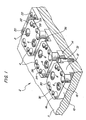
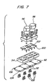
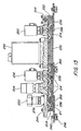
- a first embodiment of the present invention is disclosed wherein a composite manifold assembly 2 can be mounted on an appropriate support surface by combining individual manifold blocks to form an operative system.
- each of the three manifold blocks 4 are identical and are formed from a stainless steel material such as 316L stainless steel.
- V-shaped gas passageways are provided in each of the manifold blocks and as shown in Figure 1, the passageways have access ports positioned on a common upper surface 38.
- the flow path will be considered to extend from left to right although it could just as easily be reversed and, accordingly, the entrance port 6 is shown on the upper surface 38 along with an exit port 8.
- the entrance port 6 is partially on an upper flange member 10 which is cantilevered from a central manifold body portion 12.
- a lower flange member 14 is dimensioned to have a complimentary configuration to match the upper flange member 10 of the immediately adjacent manifold block.
- an active component not shown in Figure 1
- the upper flange member 10 is offset from the central manifold body portion 12 by a gap of approximately 2 inches with the distance between the center point of the respective entrance port and exit port being approximately 1/2 inch. This gap beneath an active component can facilitate the detection of any gas leakage as can be appreciated by a person skilled in this field.
- the gas stick can be mounted in a sealed housing for safety purposes and to control the purging of any leaking gases from the gas delivery system.
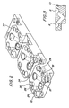
- a pair of appropriate bore holes 16 and 18 on an upper flange member 10 have a lower beveled surface to enable a self-aligning of any bolt fasteners.
- the respective bores 16 and 18 appropriately align with threaded apertures 20 and 22 on the lower flange member 14 of an adjacent manifold block.
- a pair of threaded bores 24 and 26 and 28 and 29 are provided on each perimeter side to enable the fastening of a flange on an active component as can be seen in Figure 4 and 5.
- a pair of recesses 30 and 32 on opposite sides are also provided to accommodate any protrusion of screws for fastening a keeper member to the bottom of an active component.
- the bore opening 16 and 18 have sufficient depth that when an appropriate fastener is sealed, there is still sufficient vertical room above a fastener to accommodate the protruding head of any fastening screw or bolt associated with the keeper member.
- through holes 34 and 36 are provided on either side of the lower flange members 14 to thereby accommodate a fastener 31 for attachment to a lower support surface 7.
- the upper flange member 10 are appropriately tapered or cut to facilitate access, for example, by an Allen wrench, to any such fasteners 31.
- the first embodiment of the present invention utilizes a plurality of manifold blocks 4 having specific upper flange members 10 and lower flange members 14 that are cantilevered from a central manifold body portion 12 to enable the individual manifold blocks to be interconnected to accommodate a specific fluid distribution system.
- Each of the manifold blocks 4 have a fluid passageway with an entrance port 6 and an exit port 8 that access a common upper surface 38.
- the dimensions of the upper flange member 10 and the lower flange member 14 are such that they extend across each other and thereby provide means for removably interlocking a pair of adjacent manifold blocks 4 to operatively permit their respective fluid passageways to be positioned for interconnection.
- FIG. 3 a cross-section view taken along a central longitudinal line extending from an entrance port 6 to an exit port 8 is shown for an alternative manifold block 40 that can be used as an end piece in the manifold block system.
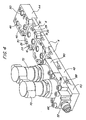
- This end piece manifold block 40 can also interface with a dual lower flange manifold block 42 in the gas stick shown in Figure 4 and 5.
- a series of three identical manifold blocks 4 are stacked from the dual lower flange manifold 42 and terminate in a junction end piece 44.
- junction end piece manifold block 44 basically discloses a passageway of T-configuration wherein the entrance port 46 is fluidly connected with a pair of exit ports 48 and 50 on either side ofthe manifold block 44. Equivalent holes and bores are included to enable an extension of the gas stick system at right angles to the longitudinal axis of the gas stick system shown in Figure 4.
- a tube coupler 52 is mounted on top of the end piece 40 manifold block with a keeper member 54 supporting an appropriate seal 56 and a pair of split ring plastic retainers 58.
- a pair of threaded bolts 60 and 62 can interlock the end piece manifold block 40 to the dual lower flange manifold block 42. The seal is accomplished by simply tightening the respective threaded bolts 66. Screws or fasteners 64 can hold the keeper member 54 with the seal member 56 and split ring retainers 58 in place to the bottom of the tube coupler 52.
- the pair of bolts 66 secure the tube coupler 52 to the surface of the end piece manifold block 40 in alignment with the entrance port 68.
- valve assemblies 70 and 72 A similar arrangement is provided with regards to each of the active components such as the valve assemblies 70 and 72.
- Appropriate keeper members 74 and 76 support seals 78 and 80 and split ring retainers 82 and 84.
- Bolts 86 are used to fasten the flanges 88 and 90 on the respective active components 70 and 72 to the upper surface of the end piece manifold block 40, the dual lower flange manifold block 42 and a manifold block 4.
- the active component 70 is mounted immediately adjacent to the tube coupler 52 which in turn can be connected to an appropriate gas line (not shown) while the active component 72 bridges the upper surface of the dual lower flange manifold block 42 and the adjacent manifold block 4 as shown in Figure 4.
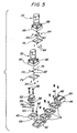
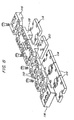
- connector plates 92 are individually provided to extend across the lower surface of individual manifold blocks 94. Again, each of the individual blocks 94 are identical and have the appropriate gas passageway and threaded bores and bore openings as described with regards to the manifold block 4. Active components 96 and 98 can be mounted on the common upper surface of the respective manifold blocks 94 within an appropriate seal keepers 100 and seals 102 as previously described with regards to the first embodiment.
- the comers of each of the connector plates 92 are appropriately notched or recessed 104 with an appropriate bore 106 at each of the comers.
- a fastener bolt 108 can extend upward for a threading engagement with a threaded bore (not shown) on the bottom of each of the manifold blocks 94.
- the thickness of the connector plates 92 and the vertical dimension of the notches 104 are such to permit the heads of the fasteners to be located within the notches.
- the connector plates 92 can be identically manufactured and will provide sufficient strength when they bridge or cross over beneath each of the manifold blocks 94 to hold the common surfaces ofthe collective manifolds blocks 94 in a common plane.
- the means for removably interlocking a pair of adjacent manifold blocks 94 to operatively permit their respective fluid passageways to be positioned for interconnection with an active component part is accomplished as a result of the identical connector plates 92.
- Figure 9 discloses a cross-sectional view of a manifold block 110.
- a plan view of the bottom side of the manifold block 110 is shown in Figure 10 wherein a central rib member 112 accommodates the V-gas passageway.
- the connector plates 114 are appropriately notched at each side of the connector plate 114 to thereby accommodate the rib projection 112.
- a plurality of different manifold blocks can be used in this system starting with the L-shaped end manifold block 116, the subsequent adjacent manifold blocks 110, the T-shaped manifold block 118 and terminating with another end manifold block 116.
- Appropriate fastener bolts can be used to join the individual manifold blocks to the appropriate connector plates as previously described with appropriate keepers and seals.
- each of the manifold blocks will have an entrance and exit port for accessing a common surface although the individual manifold blocks can be varied in shape.
- the means for removably interlocking a pair of adjacent manifold blocks to operatively permit the respective fluid passageways to be positioned for interconnection on a common surface can be provided by the connector plates 114 and the spacer connector plate 120.
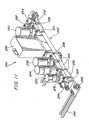
- a third embodiment of the present invention is disclosed in Figures 11-22.
- the third embodiment incorporates the advantages of individual manifold blocks that can be used to construct a manifold system and can enable the easy removal and replacement of active components in a gas stick.
- the third embodiment further provides an advantage in disclosing a vertical alignment system that helps ensure that a common surface is maintained on each of the individual surfaces of the manifold blocks with the collective surfaces being in a common plane to facilitate a sealing connection between active components and their respective manifold blocks.
- the third embodiment can have an active component firmly fixed to only a single manifold block, while still permitting the active component to bridge over a pair of individual adjacent manifold blocks to form with those individual manifold blocks an operative gas stick to deliver gas to a semiconductor tool.
- manifold blocks can comprise the plurality of manifold blocks used to construct the manifold system of the third embodiment.
- the different manifold blocks can be used to accommodate different types of active components, branching of the fluid passageway and active components that can interconnect with more than a single pair of entrance and exit ports.
- Each of the entrance and exit ports are provided on an upper surface of the manifold blocks so that they will share a common surface and be positioned within a common longitudinal plane.
- the upper and lower flanges that extend from a central body portion are further defined to be in the shape of a male and female structure or a dovetail configuration.
- the particular shape of the interconnection between the flanges is not as important as the ability to accommodate an alignment system and sets of mounting apertures to ensure a precise sealing between each of the active components and their interface with the manifold blocks.
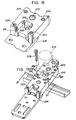
- a gas stick 200 is shown with a manifold system 202 constructed of a plurality of individual manifold blocks.
- An end manifold block 204 includes an upper flange portion 206 connected to a central body portion 208. Since this end manifold block 204 is designed to only interface with the first adjacent manifold block 214, it does not have a lower complementary flange on the opposite side of the central body portion 208 from the upper flange 206.
- the upper flange 206 provides a male member of a substantially square configuration cantilevered from a larger central body portion 208.
- the upper flange member 206 has an exit port 210 that is connected by a fluid passageway 211 of a V-shape that extends through the central body portion 208 and a portion of the fluid passageway can be seen in Figure 13 and also in Figure 22.
- the fluid passageway 211 contacts the entrance port 212.
- the manifold blocks can be formed of a 316L stainless steel.
- a plurality of identical manifold blocks 214 with both an upper flange 216 of a male configuration and a lower flange 218 of a female configuration can be interconnected, as shown in Figure 11.
- the lower flange 218 is encompassed on three sides by a continuation of the common surface from the central body portion 220, thereby providing a relief of the configuration of the upper flange 216.
- the resulting side legs or prongs 222 that extend upward on opposite sides of the lower flange 218 advantageously support mounting apertures 224.
- An additional pair of mounting apertures 224 are also positioned on the central body portion 220 to enable the ends or corners of an active component to be firmly fastened to a single manifold block.
- the adjacent upper flange 216 or male component can be mounted within the female component and its vertical thickness is such to provide a common upper surface with the central body portion 220. In essence, the male upper flange 216 with an exit port will be compressed or pinched between the lower flange 218 surface and the bottom ofthe active component to ensure appropriate alignment of the exit port 210.
- Figure 17 discloses in phantom lines the passageway between an entrance port and exit port in a manifold block 214.
- the vertical alignment system which can include a pair of dowel pins or mounting posts 226, extends vertically upward from the lower flange surface 218.
- the cylindrical dowel pins 226 can be press-fit into appropriate apertures that are drilled and sized on the surface on the lower flange 218 to form the post members.
- machining cost can be substantially reduced and the dowel pins 226 can be purchased with accurate dimensions.
- a vertical receptacle system can include a pair of appropriately spaced and sized through-bores 228 to receive the post members 226.
- the thickness of the male member relative to the height of the dowel pins 226 ensures that there will be no tilting between adjacent manifold blocks when interconnected and aligned so that there will be no accumulative bowing across the length of the gas stick. While the vertical alignment system is disclosed with a pair of post members, a single pin of a configuration that would prevent any horizontal pivotal movement, such as an oval pin, diamond, square, etc., could be used.
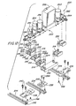
- a double female connector block 230 can be used to link a pair of male ends of manifold blocks 214.
- a double exit port end manifold block 232 completes the manifold system 202.
- Conventional mounting channels 234 can be combined with mounting brackets 236 and 238 to secure the manifold system to a support surface (not shown).
- Bolts with hex heads 240 for receiving an Allen wrench can be used to secure a mounting bracket to a mounting channel 234.
- the bolts 240 can be secured to a spring nut 242 that can be subjectively positioned anywhere along the mounting channel 234, as known in the art
- an initial VCR fitting 244 can be directly secured to the manifold block 204 to provide a fitting for connection to a source of gas.
- the exit port 210 on the upper flange 206 will be nestled within and over the lower flange 218 on the adjacent manifold block 214.
- the mounting apertures 246 which constitute the vertical alignment receptacles will receive the post members 226 that extend vertically upward from the lower flange 218.
- the relative thickness in the vertical direction of the upper flange 206 ensures that there will be no tilt because of the close tolerances of the post members 226 when received within the mounting apertures 246.
- the horizontal upper surface of the end mounting manifold block 204 will lie in a common plane with a horizontal upper surface of the adjacent manifold block 214.
- an active component such as a manual on/off valve 250
- a sealing connection is made with the entrance port 252 so that the manual on/off valve 250 can control gas into the gas stick.
- the base of the manual on/off valve 250 is anchored securely by bolts 278 to only the manifold block 214, although it is sealed across the common surfaces of the end manifold block 204 and the manifold block 214, as can be seen in the cross-sectional configuration of Figure 13.
- a cross-section of the manifold system is taken along the center line so that the active component mounting apertures are not shown.
- the active components such as the manual on/off valve 250, will bridge across adjacent manifold blocks, such as the end manifold block 204 and the immediately adjacent manifold block 214 to provide a continuity of a fluid passageway through the gas stick.
- the active component 250 is only anchored and secured to provide an appropriate pressure seal by bolts 278, that can be manually tightened from above the manifold system, with the bolts 278 extending through sets of mounting apertures 224 in the central portion 220 and the prongs 222 of the manifold block 214.
- Similar arrangements of mounting active components on adjacent manifold blocks, all of which share the common horizontal surface, is repeated across the gas stick shown in Figures 11 and 13.
- pressure regulator 254 is anchored only on the second manifold block 214, while a pneumatic shut-off valve 256 is likewise mounted only on the succeeding manifold block 214.
- a mass flow controller 258 is mounted only on the double female connector manifold block 230, while a pneumatic shut-off valve 260 is mounted directly on another manifold block 214 with its male upper flange member aligned and captured by the appropriate alignment systems between the double female connector manifold block 230 and the vertical receptacle system of the male flange member.
- VCR fittings 262 and 264 are mounted on a double exit port manifold block 232. These fittings permit a branching of the gas flow path to an adjacent set of manifold distribution systems.
- the mounting brackets 236 and 238 can be attached by bolts 240 to the mounting channels 234 through the spring nuts 242. Screws 266 can be mounted from underneath the appropriate mounting brackets 236, 238 for securing the appropriate manifold blocks through threaded apertures.
- the mounting apertures 224 can be seen extending vertically downward from the horizontal surface.
- the lower flange 218 supports the post members 226.
- Centrally positioned between the mounting post 226 is a threaded hole 268 that can receive a screw 266 for attachment to the mounting bracket.
- the threaded hole could also accommodate a longer threaded screw to exert an upper force, if desired, in releasing a male upper flange from a female interconnection.
- the male configuration is dimensioned to be smaller and not come into contact with the internal walls of the female connection.
- an exit fluid passageway 270 is disclosed.
- an active component when appropriately mounted into the mounting apertures 224 is firmly anchored on only one manifold block 214, although it is capable of bridging over the male upper flange 216 of an adjacent manifold block.
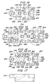
- FIG. 14 a top plan view of a manifold block having one entrance port and two exit ports is disclosed.
- Through-holes 280 can permit access from the upper surface to Allen head bolts 282, as shown in Figure 21.
- Threaded mounting holes 224 are disclosed to receive the mounting bolts 278 for fastening an active component to the manifold block.
- Mounting posts 248 are positioned on either side of the threaded hole 268.
- the mounting apertures 246 on the male member is shown and has a size that complements the mounting posts 248
- a series of blind holes that are counter bores 286 can be provided on the horizontal surface ofthe manifold block to accommodate screw heads, for example, in mounting the keepers for sealing the blocks.
- Threaded holes 294 can be used as mounting holes for providing a branching function, mounting fittings, etc.
- the counter bores 292 can function in a manner analogous to the counter bores 286.
- the threaded holes and counter bores while provided on a manifold block, need not be utilized in each arrangement or construction of a gas stick, but rather are optionally provided to permit different configurations.
- the dotted lines between the ports 296 on each of the manifold blocks shown in Figures 14, 15, and 16 disclose the flow paths through the body of the manifold blocks.
- the manifold block of Figure 14 can be used to provide a complementary fluid path branch between two active components.
- the manifold block of Figure 15 provides a provision for an interconnection with a fluid path traverse to the flow direction of interlocking manifold blocks, while having an active component modify the flow through such a cross-connection, for example, to implement a purging function.
- the manifold block of Figure 16 would enable interconnection, for example, of a T-shape block 232 into the middle of a gas stick to permit a branching of the flow path traverse to the flow direction ofthe interlocking manifold blocks.
- manifold blocks can be provided for specific flow connections by a person of skill in the field, while still enjoying the benefits of the present invention.
- a keeper 274 can mount an annular seal 276 to ensure appropriate sealing in the interconnection between an active component and a fluid conduit in a manifold block.
- the seal 276 can be deformed under the sealing pressure that is applied by the tightening of the mounting bolts 278. Similar keepers and seals are mounted between each active component and its corresponding manifold blocks.
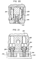
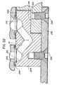
- FIG 20 a cross-sectional view taken along the line 20-20 in Figure 19 of the interface between the coupling of a pair of manifold blocks and their relationship to an overlaying active component is disclosed.
- the dowel pins that form the mounting post 248 are aligned within the mounting apertures 246.
- the threaded bore hole that is positioned between the two apertures in the lower flange precedes the flat-headed screw 266 for securing the manifold block to a mounting bracket 236.
- FIG. 21 An alternative cross-sectional view is shown in Figure 21, which could be taken along the line 21-21 in Figure 19.
- the through hole 280 is not threaded and opens into an enlarged offset 282 that can accommodate mounting bolts 283.
- an Allen wrench can be inserted down the through holes 280 to permit a tightening and a loosening of the Allen-headed bolts 284.
- the spring nuts 242 can secure the mounting bracket 238 to the mounting channel 234.
Abstract
Description
Claims (37)
- A manifold system (2) for enabling a distribution of fluids comprising:wherein the means for removably interlocking the pair of adjacent manifold blocks is characterised in that it includes, on a first manifold block (4) of the plurality of individual manifold blocks, a central body portion (12), a first flange (10) extending in a first direction from the central body portion (12), and a second flange (14) extending in a second direction from the central body portion (12).a plurality of individual manifold blocks (4), each manifold block (4) having a fluid passageway with an entrance (6) and exit (8) port accessing a common surface (38); andmeans for removably interlocking a pair of adjacent manifold blocks (4) to operatively permit their respective fluid passageways to be positioned for interconnection;
- The manifold system of claim 1, wherein the first direction is opposite to the second direction.
- The manifold system of any of claims 1-2, wherein the first flange (10) extends in a cantilevered manner from an upper surface of the central body portion (12) of the first manifold block (4), and wherein the second flange (14) extends in a cantilevered manner from a lower surface of the central body portion (12) of the first manifold block (4).
- The manifold system of claim 3, wherein the upper surface of the central body portion (12) of the first manifold block (4) is co-planar with the common surface (38).
- The manifold system of any of claims 1-4, wherein the first flange (10) and the second flange (14) have complimentary configurations that permit the first manifold block (4) to be interlocked with an adjacent manifold block (4).
- The manifold system of any of claims 1-2, wherein the first flange and the second flange extend in a cantilevered manner from an upper surface of the central body portion of the first manifold block (118).
- The manifold system of claim 6, wherein the center body portion of the first manifold block (110) includes a rib (112) that accommodates the fluid passageway.
- The manifold system of any of claims 6-7, wherein the upper surface of the central body portion of the first manifold block (110) is co-planar with the common surface.
- The manifold system of any of claims 1-2, wherein the first flange and the second flange extend in a cantilevered manner from a lower surface of the central body portion of the first manifold block (42).
- The manifold system of claim 9, wherein an upper surface of the central body portion of the first manifold block (42) is co-planar with the common surface.
- The manifold system of any of claims 1-8, wherein one of the entrance (6) and exit (8) ports extends onto the first flange (10) of the first manifold block (4).
- The manifold system of any of claims 1-11, wherein the first flange (10) has at least one aperture (16, 18) to enable attachment of the first flange (10) to a cantilevered flange (14) of an adjacent manifold block (4).
- The manifold system of any of claims 1-12, wherein each of the first flange (10) and the second flange (14) has at least one aperture (36) to enable attachment of the first manifold block (4) to a support surface (7).
- The manifold system of any of claims 1-13, wherein the first manifold block (4) has a fastening aperture (24, 26, 28, 29) to permit an active component (70, 72) to be mounted directly to the first manifold block (4) in sealing engagement therewith.
- The manifold system of claim 14, wherein the fastening aperture (24, 26, 28, 29) permits the active component (70, 72) to be mounted directly to the first manifold block (4) in sealing engagement therewith while also being sealingly connected to an adjacent manifold block (4).
- The manifold system of any of claims 1-15, wherein each of the plurality of manifold blocks (4) has entrance (6) and exit (8) ports positioned only upon an upper horizontal surface that forms the common surface (38).
- The manifold system of any of claims 1-5, wherein the first flange (216) has a male configuration and the second flange (218) has a female configuration.
- The manifold system of claim 17, wherein one of the entrance and exit ports of the first manifold block (214) is positioned on the first flange (216).
- The manifold system of any of claims 17-18, wherein one of the first flange (216) and the second flange (218) includes an alignment aperture (228) and the other of the first flange and the second flange includes an alignment post (226) having a complimentary configuration.
- The manifold system of any of claims 17-18, wherein one of the first flange (216) and the second flange (218) includes a pair of alignment apertures (228) of circular configuration and the other of the first flange (216) and the second flange (218) includes a pair of alignment posts (226) of a cylindrical configuration, a respective depth of the alignment apertures (228) and a height of the alignment posts (226) being dimensioned such that when mated, the common surface extends in a same plane between the first manifold block (214) and an adj acent manifold block (214) with the first manifold block (214) and the adjacent manifold block (214) being maintained along a common longitudinal axis.
- The manifold system of any of claims 1-5, wherein one ofthe first flange (216) and the second flange (218) has a vertical alignment system (226) extending therefrom and the other of the first flange (216) and the second flange (218) has a complimentary vertical receptacle system (228) for interacting with a vertical alignment system on an adjacent manifold block (214).
- The manifold system of any of claims 1-5 or 16-20, wherein the plurality of individual manifold blocks (4) includes a second manifold block (4) that is identical to the first manifold block (4), and wherein the first flange (10) of the first manifold block (4) overlays the second flange (14) of the second manifold block (4).
- The manifold system of any of claims 1-21, wherein the plurality of individual manifold blocks (4) includes a second manifold block (4) having a central body portion (12) and at least one flange (10, 14) extending in cantilevered manner from the central body portion (12) of the second manifold block (4), and wherein one of the first flange (10) and the second flange (14) of the first manifold block (4) extends across the at least one flange (10, 14) of the second manifold block (4) while permitting the central body portions (12) of the first and second manifold blocks (4) to be offset from each other.
- The manifold system of any of claims 1-5, 9-10, or 17-22, wherein the plurality of individual manifold blocks includes an end piece manifold block (40) having only one flange extending from an upper surface of a body portion thereof.
- The manifold system of any of claims 1-24, wherein the common surface (38) of each of the plurality of manifold blocks (4) is aligned in a common plane to facilitate a sealing of interconnected fluid passageways.
- The manifold system of any of claims 1-25, wherein at least one of the plurality of individual manifold blocks (44) has a plurality of exit ports (48, 50).
- The manifold system of any of claims 1-26, wherein at least one of the manifold blocks (44) has a plurality of entrance ports (48, 50).
- The manifold system of any of claims 1 or 6-7, further comprising a connector plate (92) that extends to overlay the first manifold block and an adjacent manifold block.
- The manifold system of claim 28, wherein the connector plate (92) has notched lower comers (104) with a bore hole (106) and the first manifold block has corresponding bore holes to enable a fastener to fixedly interconnect the connector plate (92) to the first manifold block and the adjacent manifold block whereby the common surface of each manifold block lies in a common plane.
- The manifold system of any of claims 28-29, wherein the connector plate (92) is thin and has sufficient strength to prevent the first manifold block and the adjacent manifold block from tilting their respective common surfaces.
- The manifold system of any of claims 28-30, as dependent upon claim 7, wherein the connector plate (114) includes a notch (116) to accommodate the rib (112) of the first manifold block (110).
- The manifold system of any of claims 1-31, wherein the first manifold block (4) is removably interconnected to an adjacent manifold block (4) with a fastener (31) that can be manually applied and removed with a hand tool.
- The manifold system of any of claims 1-32, in combination with at least one active component (70, 72) that is mounted in sealing engagement with the first manifold block (4).
- The manifold system of claim 33, wherein the at least one active component (70, 72) bridges over the first manifold block (4) and an adjacent manifold block (4).
- The manifold system of any of claims 33-34, wherein the first manifold block (4) and the active component (70, 72) form at least a portion of a gas panel distribution system for semiconductor manufacturing.
- The manifold system of any of claims 33-34, wherein the first manifold block (4) and the active component (70, 72) form at least a portion of an operative gas stick to deliver gas to a semiconductor tool.
- The manifold system of any of claims 33-36, further comprising a seal assembly (74, 78, 82) that extends across the first manifold block (4) and lies in a common plane with the common surface (38) of the first manifold block (4), wherein the active component (70, 72) is mounted on the seal assembly (74, 78, 82) and is fastened to the first manifold block (4) so that it extends across the first manifold block (4) to an adjacent manifold block (4).
Applications Claiming Priority (5)
| Application Number | Priority Date | Filing Date | Title |
|---|---|---|---|
| US09/111,999 US6374859B1 (en) | 1996-10-30 | 1998-07-08 | Manifold system for enabling a distribution of fluids |
| US111999 | 1998-07-08 | ||
| US229722 | 1999-01-13 | ||
| US09/229,722 US6394138B1 (en) | 1996-10-30 | 1999-01-13 | Manifold system of removable components for distribution of fluids |
| PCT/US1999/015272 WO2000003169A2 (en) | 1998-07-08 | 1999-07-07 | Manifold system of removable components for distribution of fluids |
Publications (2)
| Publication Number | Publication Date |
|---|---|
| EP1133652A2 EP1133652A2 (en) | 2001-09-19 |
| EP1133652B1 true EP1133652B1 (en) | 2004-05-06 |
Family
ID=26809455
Family Applications (1)
| Application Number | Title | Priority Date | Filing Date |
|---|---|---|---|
| EP99933722A Expired - Lifetime EP1133652B1 (en) | 1998-07-08 | 1999-07-07 | Manifold system of removable components for distribution of fluids |
Country Status (6)
| Country | Link |
|---|---|
| US (1) | US6394138B1 (en) |
| EP (1) | EP1133652B1 (en) |
| JP (1) | JP3972172B2 (en) |
| AT (1) | ATE266166T1 (en) |
| DE (1) | DE69917064T2 (en) |
| WO (1) | WO2000003169A2 (en) |
Cited By (3)
| Publication number | Priority date | Publication date | Assignee | Title |
|---|---|---|---|---|
| CN101325150B (en) * | 2007-06-11 | 2010-06-02 | 朗姆研究公司 | Flexible manifold for integrated gas system gas panels |
| CN101506561B (en) * | 2006-08-23 | 2012-04-18 | 株式会社堀场Stec | Integrated gas panel apparatus |
| DE212020000662U1 (en) | 2019-06-24 | 2022-06-30 | Run Ze Gao | Air microfluidic and air minifluidic based active compression device and clothing |
Families Citing this family (57)
| Publication number | Priority date | Publication date | Assignee | Title |
|---|---|---|---|---|
| WO2001059343A1 (en) * | 2000-02-10 | 2001-08-16 | Pall Corporation | Fluid device assembly |
| JP3482601B2 (en) * | 2000-06-30 | 2003-12-22 | 東京エレクトロン株式会社 | Fluid control device |
| US6953048B2 (en) * | 2001-09-07 | 2005-10-11 | Circle Seal Controls, Inc. | Modular surface-mount fluid-flow system |
| US20030079786A1 (en) * | 2001-10-30 | 2003-05-01 | Diana Michael J. | Modular fluid pressure regulator with bypass |
| JP2003280745A (en) * | 2002-03-25 | 2003-10-02 | Stec Inc | Mass-flow controller |
| GB2391278A (en) * | 2002-07-30 | 2004-02-04 | David Williams | Pipe Coupling |
| US6827728B2 (en) * | 2002-08-08 | 2004-12-07 | Medivance Incorporated | Patient temperature control system |
| US6802855B2 (en) * | 2002-08-08 | 2004-10-12 | Medivance Incorporated | Patient temperature control system connector apparatus |
| WO2004021412A2 (en) * | 2002-08-27 | 2004-03-11 | Celerity Group, Inc. | Modular substrate gas panel having manifold connections in a common plane |
| GB2411696B (en) * | 2002-11-26 | 2007-05-30 | Swagelok Co | Modular surface mount fluid system |
| JP2004186243A (en) * | 2002-11-29 | 2004-07-02 | Motoyama Eng Works Ltd | Block valve, mono-block valve, and method for washing valve |
| JP4314425B2 (en) * | 2002-12-02 | 2009-08-19 | 株式会社フジキン | Fluid control device |
| US20040163590A1 (en) * | 2003-02-24 | 2004-08-26 | Applied Materials, Inc. | In-situ health check of liquid injection vaporizer |
| US6874538B2 (en) * | 2003-03-26 | 2005-04-05 | Kevin S. Bennett | Fluid delivery system |
| US7178556B2 (en) * | 2003-08-07 | 2007-02-20 | Parker-Hannifin Corporation | Modular component connector substrate assembly system |
| KR101176825B1 (en) * | 2003-10-09 | 2012-08-24 | 브룩스 인스트러먼트, 엘엘씨, | Valve assembly |
| TWI279158B (en) * | 2003-11-07 | 2007-04-11 | Celerity Group Inc | Surface mount heater |
| US7048008B2 (en) * | 2004-04-13 | 2006-05-23 | Ultra Clean Holdings, Inc. | Gas-panel assembly |
| US7320339B2 (en) * | 2005-06-02 | 2008-01-22 | Ultra Clean Holdings, Inc. | Gas-panel assembly |
| US7299825B2 (en) * | 2005-06-02 | 2007-11-27 | Ultra Clean Holdings, Inc. | Gas-panel assembly |
| US7628168B2 (en) | 2005-06-10 | 2009-12-08 | Lam Research Corporation | Optimized activation prevention assembly for a gas delivery system and methods therefor |
| JP4589846B2 (en) * | 2005-08-24 | 2010-12-01 | 株式会社堀場エステック | Body structure for mass flow controller |
| DE102005047041B3 (en) * | 2005-09-30 | 2006-12-14 | Siemens Ag | Micro fluidic system, has modules and fluid line for rinsing fluid and running into rear wall unit, where pipe flows into distributor chamber and inside of modules at its lower or back side has outlet for rinsing fluid |
| JP4780558B2 (en) * | 2005-12-09 | 2011-09-28 | 株式会社フジキン | Fitting for fluid control device and fluid control device using the same |
| US7575616B2 (en) * | 2006-02-10 | 2009-08-18 | Entegris, Inc. | Low-profile surface mount filter |
| US20070224708A1 (en) * | 2006-03-21 | 2007-09-27 | Sowmya Krishnan | Mass pulse sensor and process-gas system and method |
| US8196480B1 (en) * | 2006-04-03 | 2012-06-12 | A+ Manufacturing, Llc | Modular sample conditioning system |
| US20080009977A1 (en) * | 2006-07-10 | 2008-01-10 | Ultra Clean Holdings | Apparatus and Method for Monitoring a Chemical-Supply System |
| US20100112814A1 (en) * | 2006-09-06 | 2010-05-06 | Sowmya Krishnan | Pre-certified process chamber and method |
| TW200820318A (en) * | 2006-10-27 | 2008-05-01 | Applied Materials Inc | Facility connection positioning template |
| JP5079393B2 (en) * | 2007-05-25 | 2012-11-21 | サーパス工業株式会社 | Fluid equipment unit structure |
| US20080302426A1 (en) * | 2007-06-06 | 2008-12-11 | Greg Patrick Mulligan | System and method of securing removable components for distribution of fluids |
| US20090078324A1 (en) * | 2007-09-21 | 2009-03-26 | Ultra Clean Technology, Inc. | Gas-panel system |
| US20090114295A1 (en) * | 2007-11-06 | 2009-05-07 | Ultra Clean Holdings, Inc. | Gas-panel assembly |
| US8307854B1 (en) | 2009-05-14 | 2012-11-13 | Vistadeltek, Inc. | Fluid delivery substrates for building removable standard fluid delivery sticks |
| KR101779849B1 (en) * | 2009-06-10 | 2017-10-10 | 비스타델텍, 엘엘씨 | Extreme flow rate and/or high temperature fluid delivery substrates |
| JP5456879B2 (en) * | 2010-02-22 | 2014-04-02 | 株式会社フジキン | Mixed gas supply device |
| EP2567100B1 (en) * | 2010-05-04 | 2018-11-28 | Fluid Automation Systems S.A. | Valve sub-base |
| US8950433B2 (en) | 2011-05-02 | 2015-02-10 | Advantage Group International Inc. | Manifold system for gas and fluid delivery |
| JP5785813B2 (en) * | 2011-08-10 | 2015-09-30 | 株式会社フジキン | Fluid control device |
| JP5890984B2 (en) * | 2011-08-30 | 2016-03-22 | 株式会社フジキン | Fluid control device |
| US9188990B2 (en) | 2011-10-05 | 2015-11-17 | Horiba Stec, Co., Ltd. | Fluid mechanism, support member constituting fluid mechanism and fluid control system |
| US9109732B2 (en) | 2012-04-18 | 2015-08-18 | Vistadeltek, Llc | EZ-seal gasket for joining fluid pathways |
| US20140137961A1 (en) * | 2012-11-19 | 2014-05-22 | Applied Materials, Inc. | Modular chemical delivery system |
| US9869409B2 (en) * | 2013-01-15 | 2018-01-16 | Vistadeltek, Llc | Gasket retainer for surface mount fluid component |
| US10502321B2 (en) | 2014-01-14 | 2019-12-10 | Compart Systems Pte, Ltd. | Gasket retainer for surface mount fluid component |
| JP6186275B2 (en) * | 2013-12-27 | 2017-08-23 | 株式会社フジキン | Fluid control device |
| JP6346304B2 (en) | 2014-04-15 | 2018-06-20 | ブ、キム ゴックVU, Kim Ngoc | Malleable gasket suitable for high purity fluid transportation system |
| US10460960B2 (en) * | 2016-05-09 | 2019-10-29 | Applied Materials, Inc. | Gas panel apparatus and method for reducing exhaust requirements |
| US9785154B2 (en) * | 2017-02-13 | 2017-10-10 | Robert M. McMillan | Reconfigurable modular fluid flow control system for liquids or gases |
| US10400332B2 (en) * | 2017-03-14 | 2019-09-03 | Eastman Kodak Company | Deposition system with interlocking deposition heads |
| KR102341939B1 (en) * | 2017-11-30 | 2021-12-22 | 가부시키가이샤 후지킨 | Valve device, fluid control device and semiconductor manufacturing device using the valve device |
| WO2019112512A1 (en) * | 2017-12-05 | 2019-06-13 | 鑑鋒國際股份有限公司 | Fluid control device and joint for fluid control device |
| US10982694B2 (en) | 2017-12-05 | 2021-04-20 | Siw Engineering Pte. Ltd. | Fluid control device and connector for fluid control device |
| SG11202100362TA (en) * | 2018-07-17 | 2021-02-25 | Compart Systems Pte Ltd | Mounting structures for flow substrates |
| US20220199431A1 (en) * | 2019-04-15 | 2022-06-23 | Lam Research Corporation | Modular-component system for gas delivery |
| US20230097346A1 (en) * | 2021-09-30 | 2023-03-30 | Applied Materials, Inc. | Flow guide apparatuses for flow uniformity control in process chambers |
Family Cites Families (37)
| Publication number | Priority date | Publication date | Assignee | Title |
|---|---|---|---|---|
| US3025878A (en) | 1959-06-02 | 1962-03-20 | Robert C Hupp | Mounting panel for fluid control components |
| AT255802B (en) | 1964-09-29 | 1967-07-25 | Zd Y Prumyslove Automatisace N | Pneumatic logic system |
| US3476214A (en) | 1968-02-01 | 1969-11-04 | Mccord Corp | Divisional lubricant feeder with bypass means |
| DE2302267B1 (en) | 1973-01-18 | 1974-06-12 | Abex Gmbh Denison, 4010 Hilden | Line column for hydraulic valves |
| FR2257846B1 (en) | 1973-07-03 | 1976-05-28 | Legris France Sa | |
| FR2250907A1 (en) | 1973-11-09 | 1975-06-06 | Bouteille Daniel | Assembly baseplates for pneumatic or hydraulic distributors - tongue and groove are standard modules which connect with into rigid block |
| US4080752A (en) | 1975-05-01 | 1978-03-28 | Burge David A | Toy blocks with conduits and fluid seal means |
| US3993091A (en) | 1975-10-06 | 1976-11-23 | General Gas Light Company | Manifold and valve system |
| DE2648751C2 (en) | 1976-10-27 | 1986-04-30 | Max-Planck-Gesellschaft zur Förderung der Wissenschaften e.V., 3400 Göttingen | Device for feeding liquid or gaseous substances to a processing vessel |
| DE2704869C3 (en) | 1977-02-05 | 1980-11-20 | Festo-Maschinenfabrik Gottlieb Stoll, 7300 Esslingen | In a modular design, fluidic control circuit composed of the same assemblies containing logic circuit elements |
| US4093329A (en) | 1977-03-22 | 1978-06-06 | Robertshaw Controls Company | Manifolding means and system for electrical and/or pneumatic control devices and methods |
| DE2852685A1 (en) | 1978-12-06 | 1980-06-19 | Wabco Fahrzeugbremsen Gmbh | DEVICE WITH BASE PLATES FOR A VALVE BATTERY |
| US4352532A (en) | 1980-09-15 | 1982-10-05 | Robertshaw Controls Company | Manifolding means for electrical and/or pneumatic control units and parts and methods therefor |
| US4524807A (en) | 1982-05-21 | 1985-06-25 | Humphrey Products Company | Snap-together modular manifold construction |
| IT1222940B (en) | 1987-10-19 | 1990-09-12 | Dropsa Spa | MODULAR PROGRESSIVE HYDRAULIC DISTRIBUTOR FOR LUBRICATION SYSTEMS |
| JP2633060B2 (en) | 1990-05-30 | 1997-07-23 | ファナック株式会社 | Stacked work supply device |
| EP0485625B1 (en) | 1990-05-30 | 1995-11-22 | Fanuc Ltd. | Device for keeping and feeding stacked works |
| US5178191A (en) | 1990-09-05 | 1993-01-12 | Newmatic Controls Inc. | Modular pneumatic control systems |
| US5368062A (en) * | 1992-01-29 | 1994-11-29 | Kabushiki Kaisha Toshiba | Gas supplying system and gas supplying apparatus |
| JPH0778128A (en) | 1993-06-17 | 1995-03-20 | Kanebo Ltd | Method and device for reverse discrete cosine transformation |
| FR2708702B1 (en) | 1993-08-06 | 1995-10-20 | Vygon | Ramp of taps. |
| JPH0758721A (en) | 1993-08-17 | 1995-03-03 | Fujitsu Denso Ltd | Multiple transmission system |
| WO1995010001A1 (en) | 1993-10-06 | 1995-04-13 | Unit Instruments, Inc. | Apparatus for handling process fluid |
| US5653259A (en) | 1994-10-17 | 1997-08-05 | Applied Biosystems, Inc. | Valve block |
| US5605179A (en) | 1995-03-17 | 1997-02-25 | Insync Systems, Inc. | Integrated gas panel |
| EP0733810B1 (en) | 1995-03-24 | 2002-09-11 | Rexroth Mecman GmbH | Modular valve arrangement |
| WO1996034705A1 (en) | 1995-05-05 | 1996-11-07 | Insync Systems, Inc. | Mfc-quick change method and apparatus |
| JP2832166B2 (en) | 1995-05-19 | 1998-12-02 | シーケーディ株式会社 | Gas supply integrated unit |
| JP3546275B2 (en) | 1995-06-30 | 2004-07-21 | 忠弘 大見 | Fluid control device |
| JP3605705B2 (en) | 1995-07-19 | 2004-12-22 | 株式会社フジキン | Fluid controller |
| TW347460B (en) | 1995-11-29 | 1998-12-11 | Applied Materials Inc | Flat bottom components and flat bottom architecture for fluid and gas systems |
| KR100232112B1 (en) * | 1996-01-05 | 1999-12-01 | 아마노 시게루 | Gas supply unit |
| US5662143A (en) | 1996-05-16 | 1997-09-02 | Gasonics International | Modular gas box system |
| US5992463A (en) | 1996-10-30 | 1999-11-30 | Unit Instruments, Inc. | Gas panel |
| JP4022696B2 (en) * | 1996-11-20 | 2007-12-19 | 忠弘 大見 | Circuit breaker |
| US6302141B1 (en) | 1996-12-03 | 2001-10-16 | Insync Systems, Inc. | Building blocks for integrated gas panel |
| US5860676A (en) | 1997-06-13 | 1999-01-19 | Swagelok Marketing Co. | Modular block assembly using angled fasteners for interconnecting fluid components |
-
1999
- 1999-01-13 US US09/229,722 patent/US6394138B1/en not_active Expired - Lifetime
- 1999-07-07 DE DE1999617064 patent/DE69917064T2/en not_active Expired - Fee Related
- 1999-07-07 JP JP2000559369A patent/JP3972172B2/en not_active Expired - Fee Related
- 1999-07-07 EP EP99933722A patent/EP1133652B1/en not_active Expired - Lifetime
- 1999-07-07 AT AT99933722T patent/ATE266166T1/en not_active IP Right Cessation
- 1999-07-07 WO PCT/US1999/015272 patent/WO2000003169A2/en active IP Right Grant
Cited By (3)
| Publication number | Priority date | Publication date | Assignee | Title |
|---|---|---|---|---|
| CN101506561B (en) * | 2006-08-23 | 2012-04-18 | 株式会社堀场Stec | Integrated gas panel apparatus |
| CN101325150B (en) * | 2007-06-11 | 2010-06-02 | 朗姆研究公司 | Flexible manifold for integrated gas system gas panels |
| DE212020000662U1 (en) | 2019-06-24 | 2022-06-30 | Run Ze Gao | Air microfluidic and air minifluidic based active compression device and clothing |
Also Published As
| Publication number | Publication date |
|---|---|
| WO2000003169A3 (en) | 2001-07-05 |
| EP1133652A2 (en) | 2001-09-19 |
| WO2000003169A2 (en) | 2000-01-20 |
| JP3972172B2 (en) | 2007-09-05 |
| US6394138B1 (en) | 2002-05-28 |
| ATE266166T1 (en) | 2004-05-15 |
| DE69917064T2 (en) | 2005-01-20 |
| DE69917064D1 (en) | 2004-06-09 |
| JP2002520554A (en) | 2002-07-09 |
Similar Documents
| Publication | Publication Date | Title |
|---|---|---|
| EP1133652B1 (en) | Manifold system of removable components for distribution of fluids | |
| US6374859B1 (en) | Manifold system for enabling a distribution of fluids | |
| US6435215B1 (en) | Gas panel | |
| US5836355A (en) | Building blocks for integrated gas panel | |
| TWI481792B (en) | Universal fluid flow adaptor, method of forming the smae and gas delivery apparatus | |
| US6302141B1 (en) | Building blocks for integrated gas panel | |
| US8122910B2 (en) | Flexible manifold for integrated gas system gas panels | |
| US7299825B2 (en) | Gas-panel assembly | |
| US6349744B1 (en) | Manifold for modular gas box system | |
| US20080302426A1 (en) | System and method of securing removable components for distribution of fluids | |
| JPH1151226A (en) | Process gas supply unit | |
| KR100556162B1 (en) | Manifold system of removable components for distribution of fluids | |
| WO2006130774A1 (en) | Gas-panel assembly | |
| MXPA00004198A (en) | Gas panel |
Legal Events
| Date | Code | Title | Description |
|---|---|---|---|
| PUAI | Public reference made under article 153(3) epc to a published international application that has entered the european phase |
Free format text: ORIGINAL CODE: 0009012 |
|
| 17P | Request for examination filed |
Effective date: 20010205 |
|
| AK | Designated contracting states |
Kind code of ref document: A2 Designated state(s): AT BE CH CY DE DK ES FI FR GB GR IE IT LI LU MC NL PT SE |
|
| 17Q | First examination report despatched |
Effective date: 20021029 |
|
| GRAP | Despatch of communication of intention to grant a patent |
Free format text: ORIGINAL CODE: EPIDOSNIGR1 |
|
| RAP1 | Party data changed (applicant data changed or rights of an application transferred) |
Owner name: CELERITY GROUP, INC. |
|
| GRAS | Grant fee paid |
Free format text: ORIGINAL CODE: EPIDOSNIGR3 |
|
| GRAA | (expected) grant |
Free format text: ORIGINAL CODE: 0009210 |
|
| AK | Designated contracting states |
Kind code of ref document: B1 Designated state(s): AT BE CH CY DE DK ES FI FR GB GR IE IT LI LU MC NL PT SE |
|
| PG25 | Lapsed in a contracting state [announced via postgrant information from national office to epo] |
Ref country code: NL Free format text: LAPSE BECAUSE OF FAILURE TO SUBMIT A TRANSLATION OF THE DESCRIPTION OR TO PAY THE FEE WITHIN THE PRESCRIBED TIME-LIMIT Effective date: 20040506 Ref country code: LI Free format text: LAPSE BECAUSE OF FAILURE TO SUBMIT A TRANSLATION OF THE DESCRIPTION OR TO PAY THE FEE WITHIN THE PRESCRIBED TIME-LIMIT Effective date: 20040506 Ref country code: FI Free format text: LAPSE BECAUSE OF FAILURE TO SUBMIT A TRANSLATION OF THE DESCRIPTION OR TO PAY THE FEE WITHIN THE PRESCRIBED TIME-LIMIT Effective date: 20040506 Ref country code: CY Free format text: LAPSE BECAUSE OF FAILURE TO SUBMIT A TRANSLATION OF THE DESCRIPTION OR TO PAY THE FEE WITHIN THE PRESCRIBED TIME-LIMIT Effective date: 20040506 Ref country code: CH Free format text: LAPSE BECAUSE OF FAILURE TO SUBMIT A TRANSLATION OF THE DESCRIPTION OR TO PAY THE FEE WITHIN THE PRESCRIBED TIME-LIMIT Effective date: 20040506 Ref country code: BE Free format text: LAPSE BECAUSE OF FAILURE TO SUBMIT A TRANSLATION OF THE DESCRIPTION OR TO PAY THE FEE WITHIN THE PRESCRIBED TIME-LIMIT Effective date: 20040506 Ref country code: AT Free format text: LAPSE BECAUSE OF FAILURE TO SUBMIT A TRANSLATION OF THE DESCRIPTION OR TO PAY THE FEE WITHIN THE PRESCRIBED TIME-LIMIT Effective date: 20040506 |
|
| REG | Reference to a national code |
Ref country code: GB Ref legal event code: FG4D |
|
| REG | Reference to a national code |
Ref country code: CH Ref legal event code: EP |
|
| REF | Corresponds to: |
Ref document number: 69917064 Country of ref document: DE Date of ref document: 20040609 Kind code of ref document: P |
|
| REG | Reference to a national code |
Ref country code: IE Ref legal event code: FG4D |
|
| PG25 | Lapsed in a contracting state [announced via postgrant information from national office to epo] |
Ref country code: LU Free format text: LAPSE BECAUSE OF NON-PAYMENT OF DUE FEES Effective date: 20040707 |
|
| PG25 | Lapsed in a contracting state [announced via postgrant information from national office to epo] |
Ref country code: MC Free format text: LAPSE BECAUSE OF NON-PAYMENT OF DUE FEES Effective date: 20040731 |
|
| PG25 | Lapsed in a contracting state [announced via postgrant information from national office to epo] |
Ref country code: SE Free format text: LAPSE BECAUSE OF FAILURE TO SUBMIT A TRANSLATION OF THE DESCRIPTION OR TO PAY THE FEE WITHIN THE PRESCRIBED TIME-LIMIT Effective date: 20040806 Ref country code: GR Free format text: LAPSE BECAUSE OF FAILURE TO SUBMIT A TRANSLATION OF THE DESCRIPTION OR TO PAY THE FEE WITHIN THE PRESCRIBED TIME-LIMIT Effective date: 20040806 Ref country code: DK Free format text: LAPSE BECAUSE OF FAILURE TO SUBMIT A TRANSLATION OF THE DESCRIPTION OR TO PAY THE FEE WITHIN THE PRESCRIBED TIME-LIMIT Effective date: 20040806 |
|
| PG25 | Lapsed in a contracting state [announced via postgrant information from national office to epo] |
Ref country code: ES Free format text: LAPSE BECAUSE OF FAILURE TO SUBMIT A TRANSLATION OF THE DESCRIPTION OR TO PAY THE FEE WITHIN THE PRESCRIBED TIME-LIMIT Effective date: 20040817 |
|
| NLV1 | Nl: lapsed or annulled due to failure to fulfill the requirements of art. 29p and 29m of the patents act | ||
| REG | Reference to a national code |
Ref country code: CH Ref legal event code: PL |
|
| ET | Fr: translation filed | ||
| PLBE | No opposition filed within time limit |
Free format text: ORIGINAL CODE: 0009261 |
|
| STAA | Information on the status of an ep patent application or granted ep patent |
Free format text: STATUS: NO OPPOSITION FILED WITHIN TIME LIMIT |
|
| 26N | No opposition filed |
Effective date: 20050208 |
|
| PGFP | Annual fee paid to national office [announced via postgrant information from national office to epo] |
Ref country code: IE Payment date: 20070726 Year of fee payment: 9 |
|
| PGFP | Annual fee paid to national office [announced via postgrant information from national office to epo] |
Ref country code: DE Payment date: 20070831 Year of fee payment: 9 |
|
| PG25 | Lapsed in a contracting state [announced via postgrant information from national office to epo] |
Ref country code: PT Free format text: LAPSE BECAUSE OF NON-PAYMENT OF DUE FEES Effective date: 20041006 |
|
| PGFP | Annual fee paid to national office [announced via postgrant information from national office to epo] |
Ref country code: GB Payment date: 20070727 Year of fee payment: 9 |
|
| PGFP | Annual fee paid to national office [announced via postgrant information from national office to epo] |
Ref country code: IT Payment date: 20070726 Year of fee payment: 9 |
|
| PGFP | Annual fee paid to national office [announced via postgrant information from national office to epo] |
Ref country code: FR Payment date: 20070717 Year of fee payment: 9 |
|
| GBPC | Gb: european patent ceased through non-payment of renewal fee |
Effective date: 20080707 |
|
| REG | Reference to a national code |
Ref country code: IE Ref legal event code: MM4A |
|
| PG25 | Lapsed in a contracting state [announced via postgrant information from national office to epo] |
Ref country code: DE Free format text: LAPSE BECAUSE OF NON-PAYMENT OF DUE FEES Effective date: 20090203 |
|
| REG | Reference to a national code |
Ref country code: FR Ref legal event code: ST Effective date: 20090331 |
|
| PG25 | Lapsed in a contracting state [announced via postgrant information from national office to epo] |
Ref country code: GB Free format text: LAPSE BECAUSE OF NON-PAYMENT OF DUE FEES Effective date: 20080707 |
|
| PG25 | Lapsed in a contracting state [announced via postgrant information from national office to epo] |
Ref country code: IE Free format text: LAPSE BECAUSE OF NON-PAYMENT OF DUE FEES Effective date: 20080707 |
|
| PG25 | Lapsed in a contracting state [announced via postgrant information from national office to epo] |
Ref country code: IT Free format text: LAPSE BECAUSE OF NON-PAYMENT OF DUE FEES Effective date: 20080707 Ref country code: FR Free format text: LAPSE BECAUSE OF NON-PAYMENT OF DUE FEES Effective date: 20080731 |