EP1137209A2 - Method and receiver for receiving digital broadcast signals - Google Patents
Method and receiver for receiving digital broadcast signals Download PDFInfo
- Publication number
- EP1137209A2 EP1137209A2 EP01000054A EP01000054A EP1137209A2 EP 1137209 A2 EP1137209 A2 EP 1137209A2 EP 01000054 A EP01000054 A EP 01000054A EP 01000054 A EP01000054 A EP 01000054A EP 1137209 A2 EP1137209 A2 EP 1137209A2
- Authority
- EP
- European Patent Office
- Prior art keywords
- digital radio
- radio signal
- digital
- information
- receiver
- Prior art date
- Legal status (The legal status is an assumption and is not a legal conclusion. Google has not performed a legal analysis and makes no representation as to the accuracy of the status listed.)
- Withdrawn
Links
Images


Classifications
-
- H—ELECTRICITY
- H04—ELECTRIC COMMUNICATION TECHNIQUE
- H04H—BROADCAST COMMUNICATION
- H04H60/00—Arrangements for broadcast applications with a direct linking to broadcast information or broadcast space-time; Broadcast-related systems
- H04H60/35—Arrangements for identifying or recognising characteristics with a direct linkage to broadcast information or to broadcast space-time, e.g. for identifying broadcast stations or for identifying users
-
- H—ELECTRICITY
- H04—ELECTRIC COMMUNICATION TECHNIQUE
- H04H—BROADCAST COMMUNICATION
- H04H60/00—Arrangements for broadcast applications with a direct linking to broadcast information or broadcast space-time; Broadcast-related systems
- H04H60/09—Arrangements for device control with a direct linkage to broadcast information or to broadcast space-time; Arrangements for control of broadcast-related services
- H04H60/13—Arrangements for device control affected by the broadcast information
-
- H—ELECTRICITY
- H04—ELECTRIC COMMUNICATION TECHNIQUE
- H04H—BROADCAST COMMUNICATION
- H04H60/00—Arrangements for broadcast applications with a direct linking to broadcast information or broadcast space-time; Broadcast-related systems
- H04H60/27—Arrangements for recording or accumulating broadcast information or broadcast-related information
-
- H—ELECTRICITY
- H04—ELECTRIC COMMUNICATION TECHNIQUE
- H04H—BROADCAST COMMUNICATION
- H04H60/00—Arrangements for broadcast applications with a direct linking to broadcast information or broadcast space-time; Broadcast-related systems
- H04H60/35—Arrangements for identifying or recognising characteristics with a direct linkage to broadcast information or to broadcast space-time, e.g. for identifying broadcast stations or for identifying users
- H04H60/49—Arrangements for identifying or recognising characteristics with a direct linkage to broadcast information or to broadcast space-time, e.g. for identifying broadcast stations or for identifying users for identifying locations
- H04H60/51—Arrangements for identifying or recognising characteristics with a direct linkage to broadcast information or to broadcast space-time, e.g. for identifying broadcast stations or for identifying users for identifying locations of receiving stations
-
- H—ELECTRICITY
- H04—ELECTRIC COMMUNICATION TECHNIQUE
- H04H—BROADCAST COMMUNICATION
- H04H60/00—Arrangements for broadcast applications with a direct linking to broadcast information or broadcast space-time; Broadcast-related systems
- H04H60/61—Arrangements for services using the result of monitoring, identification or recognition covered by groups H04H60/29-H04H60/54
- H04H60/65—Arrangements for services using the result of monitoring, identification or recognition covered by groups H04H60/29-H04H60/54 for using the result on users' side
-
- H—ELECTRICITY
- H04—ELECTRIC COMMUNICATION TECHNIQUE
- H04H—BROADCAST COMMUNICATION
- H04H20/00—Arrangements for broadcast or for distribution combined with broadcast
- H04H20/53—Arrangements specially adapted for specific applications, e.g. for traffic information or for mobile receivers
- H04H20/59—Arrangements specially adapted for specific applications, e.g. for traffic information or for mobile receivers for emergency or urgency
-
- H—ELECTRICITY
- H04—ELECTRIC COMMUNICATION TECHNIQUE
- H04H—BROADCAST COMMUNICATION
- H04H20/00—Arrangements for broadcast or for distribution combined with broadcast
- H04H20/65—Arrangements characterised by transmission systems for broadcast
- H04H20/67—Common-wave systems, i.e. using separate transmitters operating on substantially the same frequency
-
- H—ELECTRICITY
- H04—ELECTRIC COMMUNICATION TECHNIQUE
- H04H—BROADCAST COMMUNICATION
- H04H20/00—Arrangements for broadcast or for distribution combined with broadcast
- H04H20/86—Arrangements characterised by the broadcast information itself
- H04H20/88—Stereophonic broadcast systems
- H04H20/89—Stereophonic broadcast systems using three or more audio channels, e.g. triphonic or quadraphonic
-
- H—ELECTRICITY
- H04—ELECTRIC COMMUNICATION TECHNIQUE
- H04H—BROADCAST COMMUNICATION
- H04H20/00—Arrangements for broadcast or for distribution combined with broadcast
- H04H20/86—Arrangements characterised by the broadcast information itself
- H04H20/91—Arrangements characterised by the broadcast information itself broadcasting computer programmes
-
- H—ELECTRICITY
- H04—ELECTRIC COMMUNICATION TECHNIQUE
- H04H—BROADCAST COMMUNICATION
- H04H20/00—Arrangements for broadcast or for distribution combined with broadcast
- H04H20/86—Arrangements characterised by the broadcast information itself
- H04H20/95—Arrangements characterised by the broadcast information itself characterised by a specific format, e.g. MP3 (MPEG-1 Audio Layer 3)
-
- H—ELECTRICITY
- H04—ELECTRIC COMMUNICATION TECHNIQUE
- H04H—BROADCAST COMMUNICATION
- H04H2201/00—Aspects of broadcast communication
- H04H2201/70—Aspects of broadcast communication characterised in that receivers can be addressed
-
- H—ELECTRICITY
- H04—ELECTRIC COMMUNICATION TECHNIQUE
- H04H—BROADCAST COMMUNICATION
- H04H60/00—Arrangements for broadcast applications with a direct linking to broadcast information or broadcast space-time; Broadcast-related systems
- H04H60/09—Arrangements for device control with a direct linkage to broadcast information or to broadcast space-time; Arrangements for control of broadcast-related services
- H04H60/14—Arrangements for conditional access to broadcast information or to broadcast-related services
-
- H—ELECTRICITY
- H04—ELECTRIC COMMUNICATION TECHNIQUE
- H04H—BROADCAST COMMUNICATION
- H04H60/00—Arrangements for broadcast applications with a direct linking to broadcast information or broadcast space-time; Broadcast-related systems
- H04H60/25—Arrangements for updating broadcast information or broadcast-related information
-
- H—ELECTRICITY
- H04—ELECTRIC COMMUNICATION TECHNIQUE
- H04H—BROADCAST COMMUNICATION
- H04H60/00—Arrangements for broadcast applications with a direct linking to broadcast information or broadcast space-time; Broadcast-related systems
- H04H60/68—Systems specially adapted for using specific information, e.g. geographical or meteorological information
- H04H60/70—Systems specially adapted for using specific information, e.g. geographical or meteorological information using geographical information, e.g. maps, charts or atlases
Definitions
- the present invention relates to digital radio.
- FM Frequency Modulation
- AM Amplitude Modulation
- DAB Digital Audio Broadcast
- IBOC In-Band On-Channel
- satellite based broadcasts are in development.
- ISDB-T is under development as a standard.
- the invention provides a method for receiving information.
- the method comprises the steps of providing a search criteria, monitoring two or more digital radio signals for the search criteria, and performing an action in response to a found search criteria.
- the search criteria may be a transmission selected from a group consisting of at least one song title, at least one artist's name, at least one product, at least one program, and combinations thereof.
- the invention provides a method for verifying a credit card or check.
- the method comprises the steps of receiving a digital radio transmission comprising a list of at least one of bad credit cards and bad checking accounts; storing the list; comparing at least one of a presented credit card and a presented check to the stored list; and providing an output indicating results of the comparison.
- the invention provides a system for recording digital radio.
- the system comprises a receiver for receiving a first digital radio signal, a processor for processing the first digital radio signal, an input device for entering user preferences, a memory for storing the user preferences, and an output.
- the processor compares the first digital radio signal to the user preferences to determine whether to amplify the first digital radio signal.
- the invention provides a method for digital radio recording.
- the method comprises the steps of storing a user preference, receiving a first digital radio signal, comparing the user preference to the first digital radio signal to determine whether to amplify the first digital radio signal, and amplifying the first digital radio signal responsive to a positive determination.
- the invention provides a system for low power digital radio transmission.
- the system comprises a low power digital radio transmitter for transmitting a digital radio signal, a digital radio receiver for receiving the digital radio signal, and a processor for processing the digital radio signal.
- the invention provides a system for global positioning.
- the system comprises at least three digital radio transmission stations, each digital radio transmitters transmitting a digital signal comprising a location identification and a timestamp; a digital radio receiver for receiving the digital radio signals; and a processor for processing the digital radio signals and determining a global position of the digital radio receiver.
- the invention provides an animated toy.
- the toy comprises a figure (e.g., an animal or human doll or a car or truck), a digital radio receiver in the figure; and an output device selected from the group consisting of motors for moving a part of the figure and speakers.
- the digital radio receiver receives digital radio signals, and the digital radio signals comprising instructions.
- the invention provides a speaker system.
- the system comprises a transmitter for transmitting at least one digital radio signal, and at least one speaker.
- the speaker comprises a digital radio receiver.
- the invention provides a system for controlling public utility use.
- the system comprises a transmitter for transmitting a digital radio signal and a device conducting the public utility product (e.g., water, natural gas, or electricity) to a consumer's residence or place of business.
- the device comprises a digital radio receiver.
- the digital radio receiver receives the digital radio signal and controls the use of the public utility product in response to the digital radio signal.
- the invention provides a method of transmitting digital data.
- the method comprises the steps of transmitting an executable file; and transmitting a data file executed by the executable file.
- the invention provides a method for receiving digital data.
- the method comprises the steps of receiving a digital radio broadcast, in which the digital radio broadcast comprises an executable file and a data file; separating the executable file from the data file; loading the executable file on a processor; and playing the data file.
- This method may further comprise the step of storing the executable file in a memory.
- the invention provides a method of playing digital data.
- the method comprises the steps of receiving a digital radio broadcast, in which the digital radio broadcast comprises a datafile; determining a file type of the data file; determining whether an executable file that is necessary to play the data file is stored in a memory; downloading the executable file in response to a determination that the executable file is not present in the memory; loading the executable file on a processor; and playing the data file.
- the system of Fig. 1 includes transmitter 100, which broadcasts a digital radio signal.
- the digital radio signal may be broadcast to vehicles, including delivery trucks 102 and automobiles 104.
- Delivery trucks 102 and automobiles 104 may use the digital radio signal to assist in delivery planning, to receive weather and traffic updates for on-vehicle programmable devices, to receive recall notices regarding the vehicle, to receive software updates, to send and/or receive pages, to provide a personal computer terminal in the vehicle or for combinations thereof.
- the digital radio signal also may be broadcast to buildings, such as store 106 and home 108.
- the digital radio signal may be used to broadcast information regarding "bad" credit cards or checking accounts to merchants; to provide information regarding home appliances, such as recall notices or software updates; to provide a "feature phone” which provides the ability to put a person on hold with music broadcast by the digital signal; and to provide a jukebox with a source of digital music.
- the digital signal also may be broadcast to individuals 110, who use accessories. These accessories may include cellular phones, digital cameras, watches, personal data appliances (e.g., Palm PilotTM devices, manufactured by Palm, Inc.), and the like. Digital radio may enhance these accessories.
- the digital radio broadcast may include a description of a popular picture taking spot, and may be stored along with an image taken with a digital still camera. Further, digital radio may be used to transmit a signal akin to the atomic clock to watches, providing accurate timekeeping.
- search criteria is provided. This may include information, such as a model number for a recalled device, such as an appliance or an automobile; a manufacturing date for the device; a serial number for the device; and the like. It also may include a location and an orientation for a person or a vehicle. Further, it may include musical preferences, including a user's favorite artist(s); a user's favorite radio programs; a user's favorite products; or a type of product for which a user wishes to hear advertisements. Other search criteria are within the scope and spirit of this invention.
- step 204 at least one digital radio signal is monitored for the search criteria.
- a separate receiver may be provided solely to scan at least one digital radio frequency for information that matches the search criteria. It is within the scope and spirit of the present invention that a separate digital radio channel may be established to provide information for appliances. Further, it also is within the scope and spirit of the present invention that companies may establish their own digital radio station to provide information regarding that company's products.
- the digital radio broadcast that is provided may be a low power transmission. This may be the equivalent of the low power FM transmission service authorized by the Federal Communication Commission (FCC). Thus, in an embodiment of the present invention, multiple low power transmitters may be used to provide multiple digital radio signals.
- FCC Federal Communication Commission
- step 206 a determination is made as to whether the identified search criteria is found in the digital radio signal. For example, if the search criteria includes a model number for a refrigerator, a match is found when the model number is broadcast over digital radio. If the search criteria are not met, however, the system continues to monitor the digital radio.
- step 208 if a match is found, the system takes an action.
- this action may include notifying a user of the match.
- the action may include updating the software of an automobile, an appliance, or a device; switching the station being amplified to the station playing the preferred song, program, or commercial; and recording the preferred song, program, or commercial for later retrieval by a user;
- Fig. 3a relates to recall or maintenance information
- Fig. 3b relates to safety information or software updates for products.
- information identifying a specific automobile is entered. This information may include the automobile vehicle identification number (VIN), make, model, year, and the like. Alternatively, this information may be pre-programmed in the system when the vehicle is delivered from the manufacturer. Such information also may be obtained by linking a newly installed digital radio to a vehicles on-board computer.
- VIN automobile vehicle identification number
- step 304 digital radio broadcasts are monitored for recall information matching the specific automobile information. If there is a match, in step 306, the owner or operator of the automobile may be notified by suitable means, such as a light on the console; a sound, including synthesized voice; a text message; or the like; or combinations thereof.
- a maintenance organization such as an vehicle dealer or service center, may send maintenance coupons to a vehicle owner or operator for use during a future visit, such as sending a coupon every three months for a discounted oil change.
- the automobile may be equipped with a transmitting device, such as a low power analog or digital radio transmitter, that allows it to transmit vehicle information, such as diagnostic information to a local receiver.
- vehicle information such as diagnostic information
- This vehicle information then may be transmitted to a maintenance organization, where a vehicle's operating condition may be determined remotely.
- the vehicle may send a signal indicating vehicle mileage, so that necessary or routine maintenance may be scheduled.
- step 350 product information about a product, including, inter alia, an appliance or an automobile is entered.
- the product information may be preloaded on the system when it is provided from the manufacturer.
- the product information may be entered by a keyboard, a touch pad, a bar code scanner, or another suitable input device.
- step 352 the system scans the digital radio broadcasts for safety notices and product software updates. If the product information matches, in step 354, the user may be notified of the safety notice or software update. In step 356, if a software update is to be installed, in step 358, the update may be downloaded to the automobile or appliance in the form of signal encoded in the digital radio broadcast and installed to the product.
- step 354 may occur after step 356. In addition, step 354 also may occur in response to the results from decision box 356 and the return after step 358.
- a separate monitoring device may be provided for monitoring information for one or more appliances, automobiles, or devices. Therefore, a single radio receiver may be provided to monitor for safety notices or software updates for several devices, and may function to inform the user of any safety notices or software updates to the user's products. Such a radio receiver also may be equipped with a memory for storing such software upgrades, so that they may later be downloaded to the appropriate device.
- Digital audio receiver 406 includes audio output 408 and memory 410.
- a user may program digital audio receiver 406 with his or her favorite or desired radio broadcast triggers, including favorite songs, favorite artists, favorite radio programs, favorite style(s) or music, or favorite advertisements, or combinations thereof.
- a user may program receiver 406 t monitor a default station.
- Digital audio receiver 406 may have the capability of monitoring more than one station simultaneously. Referring again to Fig. 4, digital audio receiver 406 may first be tuned to listen to channel 1. When a favorite radio broadcast trigger is played on channel 2, digital audio receiver 406 takes an action. This action may include providing an alert to a user, which may be a visual or an audio alert; recording the favorite radio program; or automatically switching receiver 406 to listen to channel 2.
- the system may record the triggered broadcast on the other channel for future playback.
- the user preferences may be updated, so that favorite radio program is acquired at the earliest possible time.
- digital audio receiver 406 may provide the ability to actively "learn" a user's favorite song, artists, programs, music styles, or advertisements by monitoring the programming manually selected by the user to.
- digital audio receiver 406 may rank a user's preferences, and determine whether a discovered or located preference, e.g., the favorite song, artist, program, styles, or advertisement, on the other channel is of a higher priority than the favorite song, artist, program, styles, or advertisement on the current channel. Therefore, the user may be presented with the user's "most" favorite song, artist, program, styles, or advertisement.
- a user may have the ability to store information about a song, program, or advertisement stored in a memory for future referral.
- This information may be stored in a purely textual format, but may provide the user with information such as the song's title, artist, recording date, or information for purchasing the song, or product information, such as the name of the product in the advertisement, pricing, and retailer locations.
- a flowchart for digital audio recording is provided.
- music is received through radio 502
- it is compared to music list 504 to determine if the user has indicated a desire to obtain that music. If the music is desired, radio 502 than may determine if the music has already been saved in database 514. If the music has not been saved already, the music is saved in database 516. If the music is not included on music list 504, the user may be questioned as to whether the music playing is a desired piece of music 512. If it is desired, music list is updated in step 506 and saved in database 516. In all cases, the music is played over the radio.
- music list 504 may be updated manually 502. It can be updated to reflect the changing tastes of the user by such options as the style of music, the group, the title of the song, or some other attribute.
- Dispatch 602 serves as the operator for a plurality of delivery vehicles, such as delivery trucks 610 and 612. Dispatch may be provided with the locations of its delivery vehicles, which may be determined by Global Positioning System (GPS) 608, by radio triangulation, or by driver's reports. This information may be sent automatically by a transmitter on the delivery vehicle, or it may be sent manually.
- GPS Global Positioning System
- dispatch 602 may receive information regarding traffic patterns. This information may be received from digital radio station 604, or the information may be received from other sources. Dispatch 602 then determines a route for delivery that minimizes a particular variable. This variable may include delivery time, driving time, mileage, highway miles, city miles, or it may conform to the operator's start and stopping points. The use of other variables are within the scope and spirit of this invention.
- dispatch 602 may provide radio station 604 with the route information. Radio station 604 may transmit the route information over antenna 606 to delivery vehicles 610 and 612.
- the route information may be in the form of a map or a textual description, or both. Further, traffic information or weather information, or both, may be provided.
- dispatch 602 may be able to provide real-time directions to delivery vehicles 610 and 612 using GPS 608.
- first vehicle 702 is amplifying channel 1, which has, for example, a loud subwoofer channel, from broadcaster 706.
- Second vehicle 704 does not wish to hear or feel the subwoofer of first vehicle 704.
- a channel may be provided with independent subwoofer data in the digital radio signal from the broadcaster.
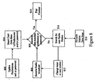
- a flow chart for setting up preferences for a radio is provided.
- the user may create a database of preferences or passwords 804 by various means 802.
- a received radio broadcast 806 matches a broadcast identified in the database of preferences 804
- the radio plays the content. If broadcast 806 does not match, the radio searches for the next radio station 814, taking advantage of the database of favorite radio stations 816. Once a new station is found, the tuner is changed to the next station 812. At this point, the process is repeated.
- the preference data base may be updated based on the recorded history of the user's listening habits.
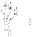
- a digital radio broadcaster 902 "stamps" a message with a pager identification code (ID) and transmits the message.
- pages are multiplexed for efficiency.
- digital radio channels may be dedicated to paging, so that receivers will recognize the channel on which their pages receive messages.
- user preference channels may be used for paging, so that the receiver need not scan or switch tuning frequency to receive the page.
- a wideband receiver may be used to detect all pages on the spectrum.
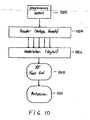
- a low power transmitter according to an embodiment of the present invention is provided.
- Programming content 1002 which may include music, data, or video, or combinations thereof, is provided for encoder 1004.
- Encoder 1004 encodes programming content 1002 into an appropriate format, such as AAC, MP3, ATRAC, Liquid Audio, or the like.
- Modulator 1006 digitally modulates the encoded programming content 1002, and passes it to RF front end 1008, which then transmits the signal via antenna 1010.
- System 1100 includes emergency vehicle 1104, such as a police vehicle, a fire truck, or an ambulance, responding to an emergency.
- Emergency vehicle 1104 includes low power transmitter 1106 for alerting vehicles, such as vehicle 1102, that such vehicles are in the path of emergency vehicle 1104, and of the presence of emergency vehicle 1100.
- Low power transmitter 1106 transmits digital radio signal 1108, which may be a siren or a voice, e.g., "Please pull to the side of the road. There is an emergency vehicle behind you.”), text, or similar means for communicating the presence of emergency vehicle 1104.
- a receiver in vehicle 1102 receives the digital radio signal and turns off any program that the driver was listening to in order to amplify digital radio signal 1108.
- the receiver in vehicle 1102 may simply mute itself until emergency vehicle 1104 passes.
- the receiver in vehicle 1102 may "turn on" when it receives digital radio signal 1108 in order to amplify it for the driver.
- a receiver receives radio broadcast data.
- This radio broadcast data may include, inter alia, an executable code (such as a decoder signal) and data.
- the executable code is separated from the data.
- the receiver determines whether the executable code is a new feature or not. For example, if a new decoding method is used, and the receiver has never received a file in this format, the decoding method or signal may be a new feature, and, in step 1208, the executable code may be loaded onto the processor. If the feature is not new, in step 1210, the data is passed onto the processor, and in step 1212, the data is executed or played.
- a "dumb" receiver may be provided. The "dumb" receiver does not store any executable code, so with every new transmission, the executable code must be passed and loaded onto the processor before the data may be executed.
- System 1300 includes at least one antenna 1306 for neighborhood 1302.
- the signal strength of the digital radio signal determines the distance of transmission of the digital radio signal.
- directional antennas may be used to "shape" neighborhood 1302 to which the signal is broadcast.
- two additional neighborhoods 1304 are shown, which are out of range of system 1300.
- Such low power digital radio transmissions may include, without limitation, neighborhood information, weather information, local events or activities (e.g., parades and marches), school closings, and other similar information that may be relevant.
- homes 1308 may receive digital radio signal from antenna 1306.
- homes 1308 include a return path 1310 via telephone line, cable TV lines, internet access lines, or the like, for providing uplink data.
- Internet service may be provided by digital radio signal.
- a conventional phone line may be used to provide the uplink to an internet service provider, while the graphic intense data is provided by the digital radio.
- Such a configuration may serve as a replacement Local Multipoint Distribution Service (LMDS), which relies on a radio transmitter at the home to send data and information back to main antenna 1306.
- LMDS Local Multipoint Distribution Service
- This method may enable feature phone or internet services with local neighborhood information broadcast content. This method also may personalize individualized Internet access through time or frequency division multiplexing of the broadcast signal.
- a feature phone may be provided.
- the feature phone of the present invention includes a digital radio receiver, and provides the ability to allow the user to place a caller on hold to digital music.
- a speaker phone-type phone may be used to amplify digital music received.
- the feature phone may receive pages, digital messages, or other sorts of transmissions.
- full power digital radio signals may be provided for several appliances.
- cellular phones may receive and amplify digital music.
- a synchronization signal may be provided for watches, so that they may remain accurate.
- digital radio jukeboxes may be provided.
- the digital radio jukebox may include a digital radio receiver that receives digital music signals from a digital radio station.
- the jukebox may be updated periodically to receive and store a new musical selection or program of selections. For example, every month, the jukebox may receive an updated music selection in order to provide variety or to stay current with the latest popular music.
- the digital radio jukebox may include a digital display to display the songs stored in the memory of the digital radio jukebox.
- a jukebox may include an uplink to a music source, so that the jukebox may request a song from a very large catalog.
- New songs or requested songs may be transmitted to the jukebox by digital radio transmission.
- a catalog of songs may be compressed and continuously transmitted.
- the jukebox would search the broadcast signal for the requested song, retrieve it, and play it at the particular jukebox.
- catalogues of different music styles such as jazz, country, rock, and classical. This would permit a single jukebox to supply almost any song desired.
- Other applications for the digital radio jukebox are within the scope and spirit of the present invention.
- system 1400 includes digital radio broadcaster 1402, which broadcasts advertisements and voice (e.g., disc jockey) and compressed audio (e.g., in MP3 format) on separate channels.
- Digital radio broadcaster 1402 broadcasts advertisements and voice (e.g., disc jockey) and compressed audio (e.g., in MP3 format) on separate channels.
- Receiver 1404 receives the digital signal from broadcaster 1404, and amplifies it via speaker 1406.
- Speaker 1406 amplifies music, advertisements, and the disc jockey.
- a display may be provided for displaying the artist's name, song title, and any visual advertisements from broadcaster 1402.
- Receiver 1404 also may include memory 1408 for storing songs that are purchased.
- Receiver 1404 may include a secure back channel that allows a user to transmit information to the broadcaster, such as a purchase account number, credit card number, and the like, to allow the user to record the song and store it in memory for future playback.
- the song may be saved in its entirety without any advertisements or without the disc jockey's voiceover.
- the song may be stored to disk storage, and then activated (e.g., paid for) at a later date by transferring the data to a personal computer and paying for the song.
- System 1500 includes first broadcaster 1502 and second broadcaster 1504, both of which broadcast digital radio signals to receiver 1510. Nevertheless, many more broadcasters may be provided. Only two are shown in the figure for simplicity of depiction.
- First broadcaster 1502 and second broadcaster 1504 each are provided with advertisements 1506, which may be local or national advertisements. Advertisements 1506 may be provided for broadcasters 1504 and 1506 by any suitable means.
- Receiver 1510 may include at least one filter 1512 for filtering incoming advertisements.
- Memory 1516 may be used to store a user's advertisement preferences (which may be entered by any suitable means, including by keyboard, by touch pad, by user listening history, or by a input device, such as a card reader, and the like.), as well as to store advertisements for a user. In one embodiment, memory 1516 also may store advertisements which a user does not want to immediately receive.
- At least one filter 1512 filters incoming advertisements 1506. Advertisements 1506 that pass through at least one filter 1512 may be displayed for a user on display 1514, amplified through a speaker (not shown), or stored in memory 1516 for future reference.
- Fig. 16a represents a FM radio spectrum between about 88.0 MHz and about 104.7 MHz.
- station 1 exists at 88.0 MHz.
- Station 2 exists at 91.7 MHz through 92.5 MHz.
- Station 3 exists at 104.7.
- Sidebands are depicted on the figure for each station. Assuming that each station provides an analog channel and a digital signal with a bit rate of 96 kBits/sec; station 2 may provide a significantly higher bit rate (i.e., 3 x 96 kBits/sec.).
- tuner 2 receives a signal having a higher bit rate than tuner 1 or tuner 3.
- a wide band tuner may be provided.
- Wide band tuner may be able to receive a significantly larger signal.
- tuner 4 may be able to receive the entire FM spectrum (from about 88 MHz to about 108 MHz), providing a very high bit rate.
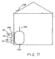
- Residential gateway 1700 includes data server 1702, which receives signals from satellite receiver 1704; radio antenna 1706 (for receiving both analog AM and FM broadcasts, as well as digital radio); cable box/modem 1708 connected to cable 1710; phone box 1712, which may include a xDSL modem, connected to phone line 1714; and power box, which may include a power line modem, connected to power line 1718.
- Residential gateway 1700 provides a user's home with several portals for accessing and for receiving data. However, it is not necessary for all portals to be provided in data server 1702.
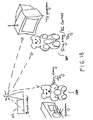
- System 1800 includes digital radio station 1802, which broadcasts a digital radio signal.
- Toy 1804 which may resemble any object, including stuffed animals, humans, robots, vehicles, and the like, may be provided with an antenna (not shown) for receiving the digital radio signal from digital radio station 1802.
- Toy 1804 may include motors, speakers, and the like for responding physically or audibly, or both, to the digital radio signal.
- Contemplated actions include singing along with a radio broadcast, moving body parts, interacting with a radio or television program, and combination thereof.
- a plurality of toys 1804 may receive one or more digital radio signals and may interact with each other.
- a low power transmitter may transmit low power digital radio signal to toy 1804.
- the digital signal may be included in a video tape, a DVD, or on a television or radio program.
- a small digital radio transmitter may be used as a remote control device for remote control toys, such as remote control cars, boats, planes, other vehicles, animals, and the like.
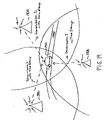
- System 1900 includes at least three digital radio stations 1902, 1904, and 1906.
- Digital radio stations 1902, 1904, and 1906 each provide a transmission that includes a time stamp.
- the transmissions also may include location information for its respective station.
- Vehicle 1910 which may be stationary, or may be traveling, receives the at least three transmissions with the time stamps.
- a processor (not shown) in vehicle 1910 processes the transmissions, and, by using the time stamp, determines the location of the vehicle.
- utility service 2002 which may be an electric company, a water company, or any other suitable utility service may communicate with digital radio station 2004.
- Digital radio station 2004 may be dedicated to utility service 2002, or it may be independent.
- Buildings 2006 which may be homes, office buildings, and the like, may include appliances (not shown) that are equipped with digital radio receiver (not shown). Examples of such appliances include, but are not limited to, air conditioning units, heat pumps, refrigerators, sprinkler systems, and water spigots.
- Digital radio station 2004 receives instruction information from utility service 2002, such as reduce water usage, reduce electricity usage, or usage of a similar public utility commodity. When an appliance receives the instruction, it complies with it until further instructions are received, or until a condition (e.g., a certain amount of time passes) is achieved.
- Examples of such actions may include: an electric utility service instructing air conditioning units to shut off for ten (10) minutes every hour during peak usage, a water utility service regulating the times that automatic sprinklers may be turned on during water rationing periods, and similar limitations on utility usage.
- a utility company may better be able to control electricity demand during a restart of service following a blackout or brownout by regulating devices that impose a heavy drain on electricity.
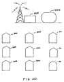
- FIG. 21 depicts wireless speaker home theater system 2100 according to one embodiment of the present invention.
- System 2100 includes a television 2102 and a digital radio transmitter 2104.
- Digital radio transmitter 2104 transmits digital radio signals to speakers which include digital radio receivers.
- Speakers may include center speaker 2106, subwoofer 2108, left front speaker 2110, right front speaker 2112, left rear speaker 2114, and right rear speaker 2116.
- Digital radio transmitter 2104 may have the capability of providing six (6) separate digital radio frequencies for the six (6) separate channels (for example, in Dolby Digital 5.1 format), such that center speaker 2106 receives f 1 , subwoofer 2108 receives f 2 , left front speaker 2110 receives f 3 , right front speaker 2112 receives f 4 , left rear speaker 2114 receives f 5 , and right rear speaker 2116 receives f 6 .
- transmitter 2104 may include conventional wire jacks for speakers, such as center speaker 2106, which may be located near transmitter 2104.
- each speaker may receive the same frequency digital radio signal and may decode the signal to determine what part of the signal it is to amplify.
- the digital radio signal received by each speaker includes the signal for all six speakers, but the speaker only amplifies the signal for its location.
- the speakers 2106-2116 may receive the signal from a remote transmitter (e.g., a broadcast tower) rather than from the local transmitter unit 2104. Each speaker again decodes the complete radio signal to determine the signal to amplify for its location.
- System 2200 includes transmitter 2202, which has antenna 2204.
- Transmitter 2202 may include an audio input device, such as microphone 2206.
- Other input devices such as music sources (including CDs, tapes, and the like) may also serve as audio inputs for transmitter 2202.
- Transmitter 2202 transmits the audio signal to speakers 2208, each of which includes digital radio receiver(s).
- Speakers 2208 are tuned to the same frequency as transmitter 2202.
- system 2200 replaces wires in a conventional paging or intercom system.
- Figs. 23-26 an application of digital radio for low power transmission is provided.
- several low power transmitters 2302 are positioned throughout a city. All of the transmitters 2302 may operate on the same frequency, but are of such a power level that their signals do not substantially interfere with each other.
- the digital radio receiver may be programmed only to "play" the signal from the strongest station. Alternatively, the digital radio may be programmed to "play" only those stations having an energy level above a given threshold.
- Each transmitter 2302 may contain information about the block or area of the city in which it is placed, such as restaurants, attractions, detailed maps, sales, entertainment, or the like. This information may be received by many devices, including receivers for amplifying the content for a user, a PDA, or similar devices.
- System 2400 includes a plurality of low power transmitters 2402 which are located on the side of a highway. Each transmitter 2402 has a limited range because of its low power nature. Each transmitter 2402 may transmit information, such as advertisements, information on services available at upcoming exits, etc. As vehicle 2404 approaches transmitter 2402, a digital radio signal is transmitted to a receiver in vehicle 2404. The digital radio signal may be amplified for the user through speakers, or it may be displayed on a display device in vehicle 2404.
- Transmitters 2402 may be provided at corners to warn of intersections, may be located near exits on highways, may be located in billboards along highways, etc.
- museum 2500 includes several low power transmitters 2502. Each low power transmitter may be positioned near an exhibit, and may transmit a digital radio signal describing the exhibit. Transmitters 2502 may have a limited range, and, therefore, may operate on the same channel. A tourist may receive the digital radio signal on a receiver, such as a PDA. Other receiving devices are within the scope and spirit of the present invention. In another embodiment, directional antennas also may be used to change the shape (and, consequently, the directional range) of the broadcast of transmitters 2502.
- a system for vehicle to vehicle communication is shown.
- vehicles 2604, 2606, 2608, 2610, and 2612 are traveling on road 2602. Nevertheless, vehicles 2604, 2606, 2608, 2610, and 2612 may be on different road, or may be stationary.
- vehicles 2608 and 2610 are transmitting low power digital radio signals having a range of 2614 and 2616, respectively.
- Radio signal 2616 from vehicle 2610 reaches vehicles 2608 and 2606, and may be received by receivers 2620, 2622, 2624, 2626, and 2628 in those vehicles.
- Radio signal 2614 from vehicle 2608 only reaches receiver 2628 in vehicle 2610.
- a method and system for the delivery of applications in digital radio is provided.
- radio broadcast technology moves towards a digital medium, the market is seeking to provide consumers with low-cost, high performance receivers that are able to decode the more complex digital signals that will be broadcast by the radio stations.
- the encoding and decoding algorithms used to transmit various types of data may be different, optimizing for performance, or bandwidth depending on the type of digital content being broadcast (i.e. music, graphics, speech, or text).
- new protocols are defined for both the transmitter and receiver.
- Another feature that may be incorporated is the reprogramming of the receiving device itself into different devices to accommodate the type of data being received.
- the "Digital Radio" medium may accommodate a wide range data types and end-use devices.
- the receiving device may be a simple device that may only recognize different encoding formats for music data (MP3, AAC, and the like), graphic data (JPEG and BMP), or encoded speech or text.
- the transmitter merely sends a data packet consisting of a header file with the encoding/encryption type (for the receiver to use in decoding the data) and the encoded data itself.
- the header portion of this packet also may include information for the number of songs/pictures that will be transmitted using the sent encoding method. For example, the header may inform the device that the next five songs will be encoded with MP3, 128kbps format). This simple packet is shown in Fig. 27a.
- the receiver may be a more complicated device, capable of reconfiguring itself depending on the application broadcast by the transmitter. This would allow the device to be, for example, initially, a cell-phone; subsequently, a radio; and, still later, a GPS mapping device.
- the reconfiguration of the device may be implemented via JavaScript (or other programming languages) running on the receiver to emulate different end equipment.
- the protocol required for this instrument is more extensive and is shown in Fig. 27b. Both protocols in Fig. 27a and Fig. 27b are standardized between the transmitter and the receiver, with respect to the number of bits in the header portion, number of bits in data type portion, and the meaning of the various configuration codes.
- These protocols require a method for transmitting a frame of data, which includes instructions (Java, C, C++, and the like), to the receiver to set its initial configuration (cell-phone, radio, and the like), the type of data to be transmitted, how the data is encoded, and finally the data itself.
- a possible implementation of the transmitter is shown in Fig. 28.
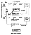
- the receiver demodulates the transmitted frame of data and examine the header packet to determine the device that the receiver should emulate. Subsequently, the receiver will identify the data type and encoding, decode the data, check for authorization keys (if appropriate) or a user identification code (if this is a subscription service), and then play the song, display the video, or the like.
- This reconfiguration may be implemented via different programs stored in local or off-chip memory, and may be initiated by the either the transmitter or the receiver.
- the reconfiguration also may be implemented in the receiver via a SIMM card or other external storage device, with a different card for each end product or service (e.g., cell-phone, web-surfing, video, and the like).
- Most receivers include two decoding paths, with the second path used for antenna diversity (to improve multipath performance) or for scanning broadcast signals for data that matches the user's preferences. Further, the receiver may recognize preferences input via a SIMM card (or similar device) or into a local memory of the receiver. In this case, the receiver decodes the frame of data and scans the data type field for information on the type of data and appropriate tags of information such as traffic, type of music, artist, song title, and the like.
- a receiver that does not have a reconfiguration capability ignores the initial header portion and only uses the data type and data portions of the frame.
- the receiver also may be narrowband, wideband, or a combination thereof (e.g., narrowband for the reception/play side, and wideband for scanning section). Possible receiver configurations are depicted in Fig. 29.
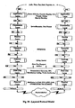
- OSI Open Systems Interconnection
- the Network layer controls who is sending the data and who should receive it.
- the Transport layer may be used to multiplex several different sources of data on to the transmission.
- the Data link layer accommodates error detection and correction functions on the channel.
- the Physical layer is the modulation mechanism itself. Referring to Fig. 30, a diagram depicts this process.
- Each layer adds at the transmitter (and strips at the receiver) header information or trailer information, or both, to the data stream that it transmits (or receives).
- the functionality of the layers is not limited to adding headers and trailers, and the layers may work with the data itself in the case of the interleaver which requires the data to be rearranged in the Data link layer.
- Security features also may be added in the application protocol layer. This allows the device to incorporate features, such as SDMI security for material recorded from the radio to limit or prevent unauthorized copying and distribution of the broadcast music.
- the security feature takes a serial number or other unique identifier from the radio hardware platform and incorporates it as part of the software encryption during recording of the broadcast. Recorded material then may only be played in the original recording device and not re-distributed.
- FIG. 31 hardware for a digital radio receiver system according to an embodiment of the present invention is depicted.
- the "Digital Radio" medium can accommodate a wide range data types and end-use devices.
- the architecture for a digital receiver system that would be used in this environment is shown in Fig. 31.
- the device contains at least two RF front ends.
- the at least two RF front ends may be used with antenna diversity algorithms to improve multipath performance.
- the second front end also allows the device to receive one channel for listening/display purposes while using the second RF front end (in combination with scanning and comparing devices or algorithms) to scan for preferred broadcast information or alerts and notify the user.
- the device also contains an input device for the user to specify preferences - i.e., preferred music, particular ads, traffic reports, artist, and the like.
- this input device may be a smart card, flash card, keypad, touch screen, or voice input.
- the system may included a location/orientation based on GPS or triangulation of the radio signals to determine the radio's position. Inclusion of a locating device, such as GPS, may be useful in automobiles to locate the position of the car and scan for traffic or weather alerts in the path of the automobile.
- the device also may contain an optional recording/storage means, such as a compact flash card or hard disk, to record music and other information for later playback.
- the system also may contain a programmable processor. At a minimum, this processor may be used to tailor the user interface to the individual. This processor also may be used to implement the scanning and comparing algorithms used to find particular broadcast information of interest to the user.
- the programmable processor also enables the receiver to be a more complicated device, capable of reconfiguring itself depending on the application broadcast by the transmitter. This added complexity allows the device to be, for example, initially, a cell-phone; subsequently, a radio; and, still later, a GPS mapping device the following minute.
- the reconfiguration of the device may be implemented via JavaScript (or other programming languages) running on the receiver to emulate different end equipment.
- the programmable processor also may be used to verify authorization keys or user ID (if this is a subscription service).
- a system and method for the transparent upgrading of technology and applications in digital radio using programmable transmitters and receivers is provided.
- the main constraint involved in the design of next generation receivers is backward compatibility to existing transmitters.
- the static nature of existing transmitter designs limits the amount of upgrading (or simplifying) that may be done to the receiver design because the receiver must adhere to a system specification that is highly dependent on the transmitter.
- the use of a programmable transmitter allows drastic changes to the overall architecture of the broadcast system. After upgrading its transmitters, the broadcaster then may either automatically upgrade the programmable receivers as the changes are made or allow the upgrade to be offered as a service feature. Therefore, the added cost of upgrading to receiver users and broadcasters is eliminated or reduced because upgrades that are programmable in nature may be readily implemented in both the receiver and the transmitter.
- Upgrades to the transmitters may take one of at least two forms.
- the upgrade may be to the system (i.e., to the technology of digital radio itself).
- the upgrade may be a service provided by the broadcaster as it incorporates new services to the digital information that it transmits.
- the former case is a design issue. Advances in algorithms, data encoding methods, error correction techniques, and other technological advances will improve the system and enable system enhancements such as better multi-path performance, higher data rates, lower noise, better audio quality, and the like.
- the programmable nature of both the transmitters and receivers may allow for a range of simple to drastic changes to be made to the overall system. The changes may be broadcast to the receivers that are already in service and incorporated to the ones that are still in design.
- the effective lifetime of the receivers and transmitters may increase, and users may avoid the necessity of constantly upgrading obsolete technology, up to an extent. Changes involving major hardware improvements or changes still must be addressed. Nevertheless, all transmitters need not be upgraded at the same time or with the same enhancements. Moreover, not all transmitters must be originally configured the same. For example, a broadcaster may chose a method of data encoding and transmission which enhances the data rate capabilities of the system, while another service provider may emphasize the audio quality at the expense of data rate transmissions. The appropriate transmission standard may be downloaded to the programmable receiver at the start of delivery of the program/service (i.e., when the listener tunes his or her dial to the radio station).
- the second of the two upgrade issues involves the services provided by the broadcasters to the users.
- the end user may be enabled to directly download (or be upgraded automatically) applications or features required to use this service.
- the term service provider here is used interchangeably with broadcaster because such solutions to the radio broadcast system deficiencies will cause broadcasters to play the role of a "service providers.”
- Such extra services may involve different software for localized mapping programs, customized program services for the individual (assuming some pre-registration for service or return path back to the broadcast service provider), and the like.
- This programmable system has an inherent, fixed physical layer portion that is the RF transmission frequency, as dictated by the government standards for the system.
- This programmable transmitter/receiver system allows the customization of service offerings per radio station and also allows broadcasters to select the preferred data encoding methods to meet their needs.
- the system also allows easy upgrades to both the transmitter and receiver sides of the system.
- a schematic of a platform for implementing a global, digital radio solution is provided.
- Current radio solutions consist of dedicated chips to meet each radio solution.
- This proliferation of chipsets may be compounded as manufacturers try to add even more products (GPS, multimedia) to their systems.
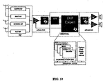
- Fig. 32 shows an implementation of such a digital radio platform according to an embodiment of the present invention.
- the platform is based on a single programmable Digital Signal Processor core that is enhanced with various custom configurable/programmable peripherals.
- This architecture will allow for rapid porting between systems because such an architecture only requires different software modules. This allows the system to decode any radio standard by loading the appropriate software from either on-chip ROM or off-chip memory.
- This DSP platform also may include a microprocessor to handle user interface tasks, LCD displays, and other add-on features.
- the various required peripherals include:
- the RF front end of the system may be replaceable because a single device may not be capable of handling the width of the required tuning spectrum, although some re-use is possible.
- the IBOC standard may use the same RF front-end as the standard AM/FM radio. Eureka-147 and Satellite may require separate front-ends.
- One approach to aggregating all the inputs is to convert the RF (Radio Frequency) signals down to a common IF (Intermediate Frequency) signal that then may be digitized by the A/D converter. Assuming common values for the IF (for example, 10.7 MHz), such digitization is within the range of fast sampling A/D converters.
- RF signals are converted directly to baseband using a zero-IF or Low-IF approach.
- the advantage of this approach is cheaper filters and cheaper A/D converters.
- a wideband RF front-end is used, the entire RF signal is frequency translated to low-IF or baseband frequencies, and the entire RF signal is digitized. This allows the DSP to extract the digital "data" information from one station and the digital "music' information from another station.
- the A/D converter may be implemented with a variable sample rate for the different standards, although this may not be necessary if a common IF or conversion to baseband method is used. Nevertheless a variable rate A/D may permit the sampling rate to be decreased when possible to conserve energy.
- the digital down converter (“DDC”) block has a programmable frequency to accommodate the different standards. This block would most likely be integrated as part of the DSP platform. Further, the output drive to the speakers would vary depending on the final end-equipment (e.g., portable, car stereo, home stereo), but would consist of a stereo (or more channel) D/A and power amplifiers.
- DDC digital down converter
- a second RF tuner may be used (with either one antenna or two antennae) to provide antenna diversity in the received signal. This diversity is used to improve the quality of the received signal in the presence of multipath signals.
- Multipath signals are delayed versions of the desired signal which are delayed in reaching the receiver due to obstructions, such as trees, buildings, or the like. The two inputs are combined at the DSP, which separates the desired signal from the delayed versions of the signal (which appear as interference signals to the desired signal).
- This additional RF tuner also may be used to capture the digital data from one radio station while the digital or analog music signal is received on the first tuner. As noted above, this data may be combined in the DSP, but used for a separate display instead of signal improvement. If this additional tuner was a wideband tuner or a narrowband tuner that was swept continuously, the DSP may be programmed to scan the digitized output for desired messages, data, or types of music. In a vehicle with separate front and back speaker systems, this dual receiver architecture also permits the user to program the second RF tuner to a separate radio signal (rather than in scan mode), so that the passengers in the front and back could listen to different stations. The RF scan mode/station selection may be under the control of the DSP/MCU.
- the platform according to the present invention also may be used to solve this problem as well.
- the DSP and microprocessor may implement the appropriate software to change the instrument to a GPS device (for example) and access data from the GPS specific front-end.
- the platform multiplexes the two RF inputs and operates as both a radio and a GPS receiver at the same time.
Abstract
Description
- The present invention relates to digital radio.
- There are various methods in place and in development for radio broadcasts around the world today. The most common standards are analog Frequency Modulation (FM) and Amplitude Modulation (AM), which are used world-wide. Even looking back at traditional FM and AM, however, variations in the spectrum used for transmission are evident.
- Various regions of the world, however, are developing new standards for transmitting and receiving digital information, rather than the traditional analog information. In Europe, Digital Audio Broadcast (DAB) is accomplished by the Eureka-147 system. In the United States of America, a method known as In-Band On-Channel (IBOC) is under development to transmit and receive digital information over the existing FM spectrum. In addition to IBOC, satellite based broadcasts are in development. In Japan, ISDB-T is under development as a standard.
- In one embodiment, the invention provides a method for receiving information. The method comprises the steps of providing a search criteria, monitoring two or more digital radio signals for the search criteria, and performing an action in response to a found search criteria. The search criteria may be a transmission selected from a group consisting of at least one song title, at least one artist's name, at least one product, at least one program, and combinations thereof.
- In another embodiment, the invention provides a method for verifying a credit card or check. The method comprises the steps of receiving a digital radio transmission comprising a list of at least one of bad credit cards and bad checking accounts; storing the list; comparing at least one of a presented credit card and a presented check to the stored list; and providing an output indicating results of the comparison.
- In still another embodiment of the invention, the invention provides a system for recording digital radio. The system comprises a receiver for receiving a first digital radio signal, a processor for processing the first digital radio signal, an input device for entering user preferences, a memory for storing the user preferences, and an output. The processor compares the first digital radio signal to the user preferences to determine whether to amplify the first digital radio signal.
- In yet another embodiment, the invention provides a method for digital radio recording. The method comprises the steps of storing a user preference, receiving a first digital radio signal, comparing the user preference to the first digital radio signal to determine whether to amplify the first digital radio signal, and amplifying the first digital radio signal responsive to a positive determination.
- In a further embodiment, the invention provides a system for low power digital radio transmission. The system comprises a low power digital radio transmitter for transmitting a digital radio signal, a digital radio receiver for receiving the digital radio signal, and a processor for processing the digital radio signal.
- In still a further embodiment, the invention provides a system for global positioning. The system comprises at least three digital radio transmission stations, each digital radio transmitters transmitting a digital signal comprising a location identification and a timestamp; a digital radio receiver for receiving the digital radio signals; and a processor for processing the digital radio signals and determining a global position of the digital radio receiver.
- In yet a further embodiment, the invention provides an animated toy. The toy comprises a figure (e.g., an animal or human doll or a car or truck), a digital radio receiver in the figure; and an output device selected from the group consisting of motors for moving a part of the figure and speakers. The digital radio receiver receives digital radio signals, and the digital radio signals comprising instructions.
- In still yet a further embodiment, the invention provides a speaker system. The system comprises a transmitter for transmitting at least one digital radio signal, and at least one speaker. The speaker comprises a digital radio receiver.
- In an additional embodiment, the invention provides a system for controlling public utility use. The system comprises a transmitter for transmitting a digital radio signal and a device conducting the public utility product (e.g., water, natural gas, or electricity) to a consumer's residence or place of business. The device comprises a digital radio receiver. The digital radio receiver receives the digital radio signal and controls the use of the public utility product in response to the digital radio signal.
- In still an additional embodiment, the invention provides a method of transmitting digital data. The method comprises the steps of transmitting an executable file; and transmitting a data file executed by the executable file.
- In yet an additional embodiment, the invention provides a method for receiving digital data. The method comprises the steps of receiving a digital radio broadcast, in which the digital radio broadcast comprises an executable file and a data file; separating the executable file from the data file; loading the executable file on a processor; and playing the data file. This method may further comprise the step of storing the executable file in a memory.
- In still yet an additional embodiment, the invention provides a method of playing digital data. The method comprises the steps of receiving a digital radio broadcast, in which the digital radio broadcast comprises a datafile; determining a file type of the data file; determining whether an executable file that is necessary to play the data file is stored in a memory; downloading the executable file in response to a determination that the executable file is not present in the memory; loading the executable file on a processor; and playing the data file.
- Other objects, features, and advantages will be apparent to persons skilled in the art by the following detailed description and the accompanying drawings.
- The present invention may be more readily understood with reference to the following drawings in which:
- Fig. 1 is a schematic of a digital radio system according to one embodiment of the present invention;
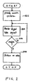
- Fig. 2 is a flowchart of a method for receiving information according to an embodiment of the present invention.;
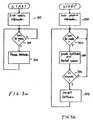
- Figs. 3a and 3b are flowcharts of methods for receiving information according to further embodiments of the present invention;
- Fig. 4 depicts a system for a recording digital audio according to an embodiment of the present invention;
- Fig. 5 is a flowchart for recording digital audio according to another embodiment of the present invention;
- Fig. 6 depicts a system for delivery planning according to an embodiment of the present invention;
- Fig. 7 depicts a system for canceling or enhancing subwoofer noise according to an embodiment of the present invention;
- Fig. 8 is a flowchart for setting digital radio preferences;
- Fig. 9 depicts a system for digital radio paging according to an embodiment of the present invention
- Fig. 10 depicts a low power transmitter according to an embodiment of the present invention;
- Fig. 11 depicts a system for low power transmitting for use with emergency vehicles according to an embodiment of the present invention;
- Fig. 12 is a flowchart for a programmable platform according to an embodiment of the present invention.;
- Fig. 13 depicts a schematic of a neighborhood digital radio broadcast system according to an embodiment of the present invention;
- Fig. 14 depicts a system for encryption in digital radio according to an embodiment of the present invention;
- Fig. 15 depicts a system for receiving preference programmable advertisements according to an embodiment of the present invention;
- Figs. 16a and 16b depict a system for providing a wideband pipe according to embodiments of the present invention;
- Fig. 17 depicts a schematic of a residential gateway according to an embodiment of the present invention;
- Fig. 18 depicts a system for entertainment according to an embodiment of the present invention;
- Fig. 19 depicts a system for global positioning according to an embodiment of the present invention;
- Fig. 20 depicts a schematic of a system for utility control according to an embodiment of the present invention;
- Fig. 21 depicts a system for digital radio receivers according to an embodiment of the present invention;
- Fig. 22 depicts a system for digital radio receivers according to an embodiment of the present invention;
- Fig. 23 depicts an application for localized low power transmission according to an embodiment of the present invention;
- Fig. 24 depicts a low power transmission, highway information system according to an embodiment of the present invention;
- Fig. 25 depicts a system for providing museum information according to an embodiment of the present invention;
- Fig. 26 depicts a system for vehicle to vehicle communication according to an embodiment of the present invention;
- Figs. 27a and 27b depict protocol packet forms according to embodiments of the present invention;
- Fig. 28 depicts a transmitter architecture according to an embodiment of the present invention;
- Fig. 29 depicts a receiver architecture according to an embodiment of the present invention;
- Fig. 30 depicts a layered protocol model according to an embodiment of the present invention;
- Fig. 31 depicts a receiver architecture according to an embodiment of the present invention; and
- Fig. 32 depicts a receiver configuration for receiving and processing various formats of digital and analog radio broadcast.
-
- Embodiments of the present invention and their technical advantages may be better understood by referring to Fig. 1. The system of Fig. 1 includes
transmitter 100, which broadcasts a digital radio signal. The digital radio signal may be broadcast to vehicles, includingdelivery trucks 102 andautomobiles 104.Delivery trucks 102 andautomobiles 104 may use the digital radio signal to assist in delivery planning, to receive weather and traffic updates for on-vehicle programmable devices, to receive recall notices regarding the vehicle, to receive software updates, to send and/or receive pages, to provide a personal computer terminal in the vehicle or for combinations thereof. - The digital radio signal also may be broadcast to buildings, such as
store 106 andhome 108. The digital radio signal may be used to broadcast information regarding "bad" credit cards or checking accounts to merchants; to provide information regarding home appliances, such as recall notices or software updates; to provide a "feature phone" which provides the ability to put a person on hold with music broadcast by the digital signal; and to provide a jukebox with a source of digital music. - The digital signal also may be broadcast to
individuals 110, who use accessories. These accessories may include cellular phones, digital cameras, watches, personal data appliances (e.g., Palm Pilot™ devices, manufactured by Palm, Inc.), and the like. Digital radio may enhance these accessories. For example, the digital radio broadcast may include a description of a popular picture taking spot, and may be stored along with an image taken with a digital still camera. Further, digital radio may be used to transmit a signal akin to the atomic clock to watches, providing accurate timekeeping. - Referring to Fig. 2, a method for receiving information is provided. In
step 202, search criteria is provided. This may include information, such as a model number for a recalled device, such as an appliance or an automobile; a manufacturing date for the device; a serial number for the device; and the like. It also may include a location and an orientation for a person or a vehicle. Further, it may include musical preferences, including a user's favorite artist(s); a user's favorite radio programs; a user's favorite products; or a type of product for which a user wishes to hear advertisements. Other search criteria are within the scope and spirit of this invention. - In
step 204, at least one digital radio signal is monitored for the search criteria. In an embodiment, a separate receiver may be provided solely to scan at least one digital radio frequency for information that matches the search criteria. It is within the scope and spirit of the present invention that a separate digital radio channel may be established to provide information for appliances. Further, it also is within the scope and spirit of the present invention that companies may establish their own digital radio station to provide information regarding that company's products. - The digital radio broadcast that is provided may be a low power transmission. This may be the equivalent of the low power FM transmission service authorized by the Federal Communication Commission (FCC). Thus, in an embodiment of the present invention, multiple low power transmitters may be used to provide multiple digital radio signals.
- In
step 206, a determination is made as to whether the identified search criteria is found in the digital radio signal. For example, if the search criteria includes a model number for a refrigerator, a match is found when the model number is broadcast over digital radio. If the search criteria are not met, however, the system continues to monitor the digital radio. - In
step 208, if a match is found, the system takes an action. In an embodiment, this action may include notifying a user of the match. In other embodiments, the action may include updating the software of an automobile, an appliance, or a device; switching the station being amplified to the station playing the preferred song, program, or commercial; and recording the preferred song, program, or commercial for later retrieval by a user; - Referring to Figs. 3a and 3b, flowcharts of a method for receiving information are provided. Fig. 3a relates to recall or maintenance information, while Fig. 3b relates to safety information or software updates for products. In Fig. 3a, in
step 302, information identifying a specific automobile is entered. This information may include the automobile vehicle identification number (VIN), make, model, year, and the like. Alternatively, this information may be pre-programmed in the system when the vehicle is delivered from the manufacturer. Such information also may be obtained by linking a newly installed digital radio to a vehicles on-board computer. - In
step 304, digital radio broadcasts are monitored for recall information matching the specific automobile information. If there is a match, instep 306, the owner or operator of the automobile may be notified by suitable means, such as a light on the console; a sound, including synthesized voice; a text message; or the like; or combinations thereof. In another embodiment, a maintenance organization, such as an vehicle dealer or service center, may send maintenance coupons to a vehicle owner or operator for use during a future visit, such as sending a coupon every three months for a discounted oil change. - In another embodiment, the automobile may be equipped with a transmitting device, such as a low power analog or digital radio transmitter, that allows it to transmit vehicle information, such as diagnostic information to a local receiver. This vehicle information then may be transmitted to a maintenance organization, where a vehicle's operating condition may be determined remotely. In addition, the vehicle may send a signal indicating vehicle mileage, so that necessary or routine maintenance may be scheduled.
- Referring now to Fig. 3b, in
step 350, product information about a product, including, inter alia, an appliance or an automobile is entered. The product information may be preloaded on the system when it is provided from the manufacturer. In another embodiment, the product information may be entered by a keyboard, a touch pad, a bar code scanner, or another suitable input device. - In
step 352, the system scans the digital radio broadcasts for safety notices and product software updates. If the product information matches, in step 354, the user may be notified of the safety notice or software update. Instep 356, if a software update is to be installed, instep 358, the update may be downloaded to the automobile or appliance in the form of signal encoded in the digital radio broadcast and installed to the product. - In another embodiment, step 354 may occur after
step 356. In addition, step 354 also may occur in response to the results fromdecision box 356 and the return afterstep 358. - In another embodiment, a separate monitoring device may be provided for monitoring information for one or more appliances, automobiles, or devices. Therefore, a single radio receiver may be provided to monitor for safety notices or software updates for several devices, and may function to inform the user of any safety notices or software updates to the user's products. Such a radio receiver also may be equipped with a memory for storing such software upgrades, so that they may later be downloaded to the appropriate device.
- Referring to Fig. 4, a system for a recording digital audio is provided. In the figure, two broadcasters are depicted. It should be recognized, however, that many different broadcasters may be provided.
First broadcaster 402 andsecond broadcaster 404broadcast channel 1 andchannel 2, respectively. Digitalaudio receiver 406 includesaudio output 408 andmemory 410. A user may programdigital audio receiver 406 with his or her favorite or desired radio broadcast triggers, including favorite songs, favorite artists, favorite radio programs, favorite style(s) or music, or favorite advertisements, or combinations thereof. In a further embodiment, a user may program receiver 406 t monitor a default station. - Digital
audio receiver 406 may have the capability of monitoring more than one station simultaneously. Referring again to Fig. 4,digital audio receiver 406 may first be tuned to listen tochannel 1. When a favorite radio broadcast trigger is played onchannel 2,digital audio receiver 406 takes an action. This action may include providing an alert to a user, which may be a visual or an audio alert; recording the favorite radio program; or automatically switchingreceiver 406 to listen tochannel 2. - In another embodiment, if a user is listening to a favorite radio program, and another favorite radio or desired broadcast trigger is found on another channel, the system may record the triggered broadcast on the other channel for future playback. In still another embodiment, when a favorite radio program is missed, the user preferences may be updated, so that favorite radio program is acquired at the earliest possible time.
- Additional programming logic for
digital audio receiver 406 may be available. This logic may provide the ability to actively "learn" a user's favorite song, artists, programs, music styles, or advertisements by monitoring the programming manually selected by the user to. In another embodiment,digital audio receiver 406 may rank a user's preferences, and determine whether a discovered or located preference, e.g., the favorite song, artist, program, styles, or advertisement, on the other channel is of a higher priority than the favorite song, artist, program, styles, or advertisement on the current channel. Therefore, the user may be presented with the user's "most" favorite song, artist, program, styles, or advertisement. - In another embodiment, a user may have the ability to store information about a song, program, or advertisement stored in a memory for future referral. This information may be stored in a purely textual format, but may provide the user with information such as the song's title, artist, recording date, or information for purchasing the song, or product information, such as the name of the product in the advertisement, pricing, and retailer locations.
- Referring to Fig. 5, a flowchart for digital audio recording is provided. When music is received through
radio 502, it is compared tomusic list 504 to determine if the user has indicated a desire to obtain that music. If the music is desired,radio 502 than may determine if the music has already been saved indatabase 514. If the music has not been saved already, the music is saved indatabase 516. If the music is not included onmusic list 504, the user may be questioned as to whether the music playing is a desired piece ofmusic 512. If it is desired, music list is updated instep 506 and saved indatabase 516. In all cases, the music is played over the radio. - Alternatively,
music list 504 may be updated manually 502. It can be updated to reflect the changing tastes of the user by such options as the style of music, the group, the title of the song, or some other attribute. - Referring to Fig. 6, a system for delivery planning is provided.
Dispatch 602 serves as the operator for a plurality of delivery vehicles, such asdelivery trucks - For example, dispatch 602 may receive information regarding traffic patterns. This information may be received from
digital radio station 604, or the information may be received from other sources.Dispatch 602 then determines a route for delivery that minimizes a particular variable. This variable may include delivery time, driving time, mileage, highway miles, city miles, or it may conform to the operator's start and stopping points. The use of other variables are within the scope and spirit of this invention. - Once
dispatch 602 determines the delivery route, it may provideradio station 604 with the route information.Radio station 604 may transmit the route information overantenna 606 todelivery vehicles delivery vehicles GPS 608. - Referring to Fig. 7, a system for canceling or providing subwoofer noise is provided. In
system 700,first vehicle 702 is amplifyingchannel 1, which has, for example, a loud subwoofer channel, frombroadcaster 706.Second vehicle 704 does not wish to hear or feel the subwoofer offirst vehicle 704.Second vehicle 704, which is equipped with a low power transmitter, which reverses the phase of the subwoofer channel ofchannel 1, which results in the subwoofer noise fromfirst vehicle 702 being locally canceled. As is apparent form the description above, in another embodiment of the present invention, a channel may be provided with independent subwoofer data in the digital radio signal from the broadcaster. - Referring to Fig. 8, a flow chart for setting up preferences for a radio is provided. The user may create a database of preferences or
passwords 804 byvarious means 802. When a receivedradio broadcast 806 matches a broadcast identified in the database ofpreferences 804, the radio plays the content. Ifbroadcast 806 does not match, the radio searches for thenext radio station 814, taking advantage of the database offavorite radio stations 816. Once a new station is found, the tuner is changed to thenext station 812. At this point, the process is repeated. Alternatively, the preference data base may be updated based on the recorded history of the user's listening habits. - Referring to Fig. 9, a system for digital radio paging is provided. A
digital radio broadcaster 902 "stamps" a message with a pager identification code (ID) and transmits the message. In an embodiment, pages are multiplexed for efficiency. A plurality of pagers, each with a unique pager ID, shown in the figure as pager ID:1 904, pager ID:2 906, and pager ID:3 908, all receive the broadcast fromdigital radio broadcaster 902. Only pager ID:2 906, however, displays the page. The other pagers ignore the message. - In another embodiment, digital radio channels may be dedicated to paging, so that receivers will recognize the channel on which their pages receive messages. In yet another embodiment, user preference channels may be used for paging, so that the receiver need not scan or switch tuning frequency to receive the page. In still another embodiment, a wideband receiver may be used to detect all pages on the spectrum.
- Referring to Fig. 10, a low power transmitter according to an embodiment of the present invention is provided.
Programming content 1002, which may include music, data, or video, or combinations thereof, is provided forencoder 1004. Encoder 1004 encodesprogramming content 1002 into an appropriate format, such as AAC, MP3, ATRAC, Liquid Audio, or the like.Modulator 1006 digitally modulates the encodedprogramming content 1002, and passes it to RFfront end 1008, which then transmits the signal via antenna 1010. - Referring to Fig. 11, a system for low power transmitting for use with emergency vehicles is provided.
System 1100 includesemergency vehicle 1104, such as a police vehicle, a fire truck, or an ambulance, responding to an emergency.Emergency vehicle 1104 includes low power transmitter 1106 for alerting vehicles, such asvehicle 1102, that such vehicles are in the path ofemergency vehicle 1104, and of the presence ofemergency vehicle 1100. Low power transmitter 1106 transmitsdigital radio signal 1108, which may be a siren or a voice, e.g., "Please pull to the side of the road. There is an emergency vehicle behind you."), text, or similar means for communicating the presence ofemergency vehicle 1104. In one embodiment, a receiver invehicle 1102 receives the digital radio signal and turns off any program that the driver was listening to in order to amplifydigital radio signal 1108. In another embodiment, the receiver invehicle 1102 may simply mute itself untilemergency vehicle 1104 passes. In yet another embodiment, the receiver invehicle 1102 may "turn on" when it receivesdigital radio signal 1108 in order to amplify it for the driver. - Referring to Fig. 12, a flowchart for a programmable platform is provided. In
step 1202, a receiver receives radio broadcast data. This radio broadcast data may include, inter alia, an executable code (such as a decoder signal) and data. Instep 1204, the executable code is separated from the data. In step 1206, the receiver determines whether the executable code is a new feature or not. For example, if a new decoding method is used, and the receiver has never received a file in this format, the decoding method or signal may be a new feature, and, instep 1208, the executable code may be loaded onto the processor. If the feature is not new, instep 1210, the data is passed onto the processor, and instep 1212, the data is executed or played. In another embodiment, a "dumb" receiver may be provided. The "dumb" receiver does not store any executable code, so with every new transmission, the executable code must be passed and loaded onto the processor before the data may be executed. - Referring to Fig. 13, a schematic of a neighborhood digital
radio broadcast system 1300 is provided.System 1300 includes at least oneantenna 1306 forneighborhood 1302. The signal strength of the digital radio signal determines the distance of transmission of the digital radio signal. In addition, directional antennas may be used to "shape"neighborhood 1302 to which the signal is broadcast. In Fig. 13, twoadditional neighborhoods 1304 are shown, which are out of range ofsystem 1300. Such low power digital radio transmissions may include, without limitation, neighborhood information, weather information, local events or activities (e.g., parades and marches), school closings, and other similar information that may be relevant. Further,homes 1308 may receive digital radio signal fromantenna 1306. In one embodiment,homes 1308 include areturn path 1310 via telephone line, cable TV lines, internet access lines, or the like, for providing uplink data. - In one embodiment, Internet service may be provided by digital radio signal. A conventional phone line may be used to provide the uplink to an internet service provider, while the graphic intense data is provided by the digital radio. Such a configuration may serve as a replacement Local Multipoint Distribution Service (LMDS), which relies on a radio transmitter at the home to send data and information back to
main antenna 1306. This method may enable feature phone or internet services with local neighborhood information broadcast content. This method also may personalize individualized Internet access through time or frequency division multiplexing of the broadcast signal. - In another embodiment, a feature phone may be provided. The feature phone of the present invention includes a digital radio receiver, and provides the ability to allow the user to place a caller on hold to digital music. In another embodiment, a speaker phone-type phone may be used to amplify digital music received. In yet another embodiment, the feature phone may receive pages, digital messages, or other sorts of transmissions. In another embodiment, full power digital radio signals may be provided for several appliances. In an embodiment, cellular phones may receive and amplify digital music. In another embodiment, a synchronization signal may be provided for watches, so that they may remain accurate.
- In a further embodiment, digital radio jukeboxes may be provided. The digital radio jukebox may include a digital radio receiver that receives digital music signals from a digital radio station. In an embodiment, the jukebox may be updated periodically to receive and store a new musical selection or program of selections. For example, every month, the jukebox may receive an updated music selection in order to provide variety or to stay current with the latest popular music. The digital radio jukebox may include a digital display to display the songs stored in the memory of the digital radio jukebox. In another embodiment, a jukebox may include an uplink to a music source, so that the jukebox may request a song from a very large catalog. New songs or requested songs may be transmitted to the jukebox by digital radio transmission. In still another embodiment, a catalog of songs may be compressed and continuously transmitted. When a song was requested at a particular jukebox, the jukebox would search the broadcast signal for the requested song, retrieve it, and play it at the particular jukebox. As is discussed in greater detail below, be used to transmit catalogues of different music styles, such as jazz, country, rock, and classical. This would permit a single jukebox to supply almost any song desired. Other applications for the digital radio jukebox are within the scope and spirit of the present invention.
- Referring to Fig. 14, a system for encryption in digital radio is provided. In the figure, system 1400 includes digital radio broadcaster 1402, which broadcasts advertisements and voice (e.g., disc jockey) and compressed audio (e.g., in MP3 format) on separate channels.
Receiver 1404 receives the digital signal frombroadcaster 1404, and amplifies it viaspeaker 1406.Speaker 1406 amplifies music, advertisements, and the disc jockey. A display may be provided for displaying the artist's name, song title, and any visual advertisements from broadcaster 1402. -
Receiver 1404 also may include memory 1408 for storing songs that are purchased.Receiver 1404 may include a secure back channel that allows a user to transmit information to the broadcaster, such as a purchase account number, credit card number, and the like, to allow the user to record the song and store it in memory for future playback. - In one embodiment, the song may be saved in its entirety without any advertisements or without the disc jockey's voiceover. In another embodiment, the song may be stored to disk storage, and then activated (e.g., paid for) at a later date by transferring the data to a personal computer and paying for the song.
- Referring to Fig. 15, a system for preference programmable advertisement receiving is provided.
System 1500 includesfirst broadcaster 1502 andsecond broadcaster 1504, both of which broadcast digital radio signals toreceiver 1510. Nevertheless, many more broadcasters may be provided. Only two are shown in the figure for simplicity of depiction. -
First broadcaster 1502 andsecond broadcaster 1504 each are provided withadvertisements 1506, which may be local or national advertisements.Advertisements 1506 may be provided forbroadcasters -
Receiver 1510 may include at least onefilter 1512 for filtering incoming advertisements.Memory 1516 may be used to store a user's advertisement preferences (which may be entered by any suitable means, including by keyboard, by touch pad, by user listening history, or by a input device, such as a card reader, and the like.), as well as to store advertisements for a user. In one embodiment,memory 1516 also may store advertisements which a user does not want to immediately receive. At least onefilter 1512 filtersincoming advertisements 1506.Advertisements 1506 that pass through at least onefilter 1512 may be displayed for a user on display 1514, amplified through a speaker (not shown), or stored inmemory 1516 for future reference. - Referring to Figs. 16a and 16b, a system for providing a wideband pipe is provided. Fig. 16a represents a FM radio spectrum between about 88.0 MHz and about 104.7 MHz. For example,
station 1 exists at 88.0 MHz.Station 2 exists at 91.7 MHz through 92.5 MHz.Station 3 exists at 104.7. Sidebands are depicted on the figure for each station. Assuming that each station provides an analog channel and a digital signal with a bit rate of 96 kBits/sec;station 2 may provide a significantly higher bit rate (i.e., 3 x 96 kBits/sec.). Thus, in the figure,tuner 2 receives a signal having a higher bit rate thantuner 1 ortuner 3. - Referring to Fig. 16b, in another embodiment, a wide band tuner may be provided. Wide band tuner may be able to receive a significantly larger signal. For example,
tuner 4 may be able to receive the entire FM spectrum (from about 88 MHz to about 108 MHz), providing a very high bit rate. - Referring to Fig. 17, a schematic of a residential gateway is provided. Residential gateway 1700 includes
data server 1702, which receives signals fromsatellite receiver 1704; radio antenna 1706 (for receiving both analog AM and FM broadcasts, as well as digital radio); cable box/modem 1708 connected tocable 1710;phone box 1712, which may include a xDSL modem, connected tophone line 1714; and power box, which may include a power line modem, connected topower line 1718. - Residential gateway 1700 provides a user's home with several portals for accessing and for receiving data. However, it is not necessary for all portals to be provided in
data server 1702. - Referring to Fig. 18, a system for entertainment is provided. System 1800 includes digital radio station 1802, which broadcasts a digital radio signal.
Toy 1804, which may resemble any object, including stuffed animals, humans, robots, vehicles, and the like, may be provided with an antenna (not shown) for receiving the digital radio signal from digital radio station 1802.Toy 1804 may include motors, speakers, and the like for responding physically or audibly, or both, to the digital radio signal. Contemplated actions include singing along with a radio broadcast, moving body parts, interacting with a radio or television program, and combination thereof. In one embodiment, a plurality oftoys 1804 may receive one or more digital radio signals and may interact with each other. - In yet another embodiment, a low power transmitter may transmit low power digital radio signal to
toy 1804. The digital signal may be included in a video tape, a DVD, or on a television or radio program. In still another embodiment, a small digital radio transmitter may be used as a remote control device for remote control toys, such as remote control cars, boats, planes, other vehicles, animals, and the like. - Referring to Fig. 19, a system for global positioning is provided. System 1900 includes at least three
digital radio stations Digital radio stations - Referring to Fig. 20, a schematic of a system for utility control is provided. In system 2000,
utility service 2002, which may be an electric company, a water company, or any other suitable utility service may communicate withdigital radio station 2004.Digital radio station 2004 may be dedicated toutility service 2002, or it may be independent. -
Buildings 2006, which may be homes, office buildings, and the like, may include appliances (not shown) that are equipped with digital radio receiver (not shown). Examples of such appliances include, but are not limited to, air conditioning units, heat pumps, refrigerators, sprinkler systems, and water spigots.Digital radio station 2004 receives instruction information fromutility service 2002, such as reduce water usage, reduce electricity usage, or usage of a similar public utility commodity. When an appliance receives the instruction, it complies with it until further instructions are received, or until a condition (e.g., a certain amount of time passes) is achieved. Examples of such actions may include: an electric utility service instructing air conditioning units to shut off for ten (10) minutes every hour during peak usage, a water utility service regulating the times that automatic sprinklers may be turned on during water rationing periods, and similar limitations on utility usage. In addition, a utility company may better be able to control electricity demand during a restart of service following a blackout or brownout by regulating devices that impose a heavy drain on electricity. - Referring to Figs. 21-22, systems for digital radio receivers/speakers are provided. Fig. 21 depicts wireless speaker
home theater system 2100 according to one embodiment of the present invention.System 2100 includes atelevision 2102 and adigital radio transmitter 2104.Digital radio transmitter 2104 transmits digital radio signals to speakers which include digital radio receivers. Speakers may includecenter speaker 2106,subwoofer 2108, leftfront speaker 2110,right front speaker 2112, leftrear speaker 2114, and rightrear speaker 2116.Digital radio transmitter 2104 may have the capability of providing six (6) separate digital radio frequencies for the six (6) separate channels (for example, in Dolby Digital 5.1 format), such thatcenter speaker 2106 receives f1,subwoofer 2108 receives f2, leftfront speaker 2110 receives f3,right front speaker 2112 receives f4, leftrear speaker 2114 receives f5, and rightrear speaker 2116 receives f6. In another embodiment,transmitter 2104 may include conventional wire jacks for speakers, such ascenter speaker 2106, which may be located neartransmitter 2104. - In another embodiment, each speaker may receive the same frequency digital radio signal and may decode the signal to determine what part of the signal it is to amplify. Thus, the digital radio signal received by each speaker includes the signal for all six speakers, but the speaker only amplifies the signal for its location. In still another embodiment, the speakers 2106-2116 may receive the signal from a remote transmitter (e.g., a broadcast tower) rather than from the
local transmitter unit 2104. Each speaker again decodes the complete radio signal to determine the signal to amplify for its location. - Referring to Fig. 22, a paging or intercom system including digital radio is provided.
System 2200 includestransmitter 2202, which hasantenna 2204.Transmitter 2202 may include an audio input device, such asmicrophone 2206. Other input devices, such as music sources (including CDs, tapes, and the like) may also serve as audio inputs fortransmitter 2202.Transmitter 2202 transmits the audio signal tospeakers 2208, each of which includes digital radio receiver(s).Speakers 2208 are tuned to the same frequency astransmitter 2202. In a further embodiment,system 2200 replaces wires in a conventional paging or intercom system. - Referring to Figs. 23-26, an application of digital radio for low power transmission is provided. In the figure, several
low power transmitters 2302 are positioned throughout a city. All of thetransmitters 2302 may operate on the same frequency, but are of such a power level that their signals do not substantially interfere with each other. Specifically, the digital radio receiver may be programmed only to "play" the signal from the strongest station. Alternatively, the digital radio may be programmed to "play" only those stations having an energy level above a given threshold. Eachtransmitter 2302 may contain information about the block or area of the city in which it is placed, such as restaurants, attractions, detailed maps, sales, entertainment, or the like. This information may be received by many devices, including receivers for amplifying the content for a user, a PDA, or similar devices. - Referring to Fig. 24, a low power transmission highway information system is provided.
System 2400 includes a plurality oflow power transmitters 2402 which are located on the side of a highway. Eachtransmitter 2402 has a limited range because of its low power nature. Eachtransmitter 2402 may transmit information, such as advertisements, information on services available at upcoming exits, etc. Asvehicle 2404 approachestransmitter 2402, a digital radio signal is transmitted to a receiver invehicle 2404. The digital radio signal may be amplified for the user through speakers, or it may be displayed on a display device invehicle 2404. -
Transmitters 2402 may be provided at corners to warn of intersections, may be located near exits on highways, may be located in billboards along highways, etc. - Referring to Fig. 25, a system for providing museum information is provided. In the figure,
museum 2500 includes severallow power transmitters 2502. Each low power transmitter may be positioned near an exhibit, and may transmit a digital radio signal describing the exhibit.Transmitters 2502 may have a limited range, and, therefore, may operate on the same channel. A tourist may receive the digital radio signal on a receiver, such as a PDA. Other receiving devices are within the scope and spirit of the present invention. In another embodiment, directional antennas also may be used to change the shape (and, consequently, the directional range) of the broadcast oftransmitters 2502. - Referring to Fig. 26, a system for vehicle to vehicle communication is shown. In the figure,
vehicles road 2602. Nevertheless,vehicles - As shown in the figure,
vehicles 2608 and 2610 are transmitting low power digital radio signals having a range of 2614 and 2616, respectively.Radio signal 2616 fromvehicle 2610 reaches vehicles 2608 and 2606, and may be received byreceivers Radio signal 2614 from vehicle 2608 only reaches receiver 2628 invehicle 2610. - Referring to Figs. 27-31 a method and system for the delivery of applications in digital radio according to an embodiment of the present invention is provided. As radio broadcast technology moves towards a digital medium, the market is seeking to provide consumers with low-cost, high performance receivers that are able to decode the more complex digital signals that will be broadcast by the radio stations. At a minimum, the encoding and decoding algorithms used to transmit various types of data may be different, optimizing for performance, or bandwidth depending on the type of digital content being broadcast (i.e. music, graphics, speech, or text). In order to manage the changeable encoding of this data stream, new protocols are defined for both the transmitter and receiver. Another feature that may be incorporated is the reprogramming of the receiving device itself into different devices to accommodate the type of data being received.
- By enabling the transmitter and receiver to both be programmable, the "Digital Radio" medium may accommodate a wide range data types and end-use devices. The receiving device may be a simple device that may only recognize different encoding formats for music data (MP3, AAC, and the like), graphic data (JPEG and BMP), or encoded speech or text. In this case, the transmitter merely sends a data packet consisting of a header file with the encoding/encryption type (for the receiver to use in decoding the data) and the encoded data itself. The header portion of this packet also may include information for the number of songs/pictures that will be transmitted using the sent encoding method. For example, the header may inform the device that the next five songs will be encoded with MP3, 128kbps format). This simple packet is shown in Fig. 27a.
- Alternatively, the receiver may be a more complicated device, capable of reconfiguring itself depending on the application broadcast by the transmitter. This would allow the device to be, for example, initially, a cell-phone; subsequently, a radio; and, still later, a GPS mapping device. The reconfiguration of the device may be implemented via JavaScript (or other programming languages) running on the receiver to emulate different end equipment. The protocol required for this instrument is more extensive and is shown in Fig. 27b. Both protocols in Fig. 27a and Fig. 27b are standardized between the transmitter and the receiver, with respect to the number of bits in the header portion, number of bits in data type portion, and the meaning of the various configuration codes. These protocols require a method for transmitting a frame of data, which includes instructions (Java, C, C++, and the like), to the receiver to set its initial configuration (cell-phone, radio, and the like), the type of data to be transmitted, how the data is encoded, and finally the data itself. A possible implementation of the transmitter is shown in Fig. 28.
- The receiver demodulates the transmitted frame of data and examine the header packet to determine the device that the receiver should emulate. Subsequently, the receiver will identify the data type and encoding, decode the data, check for authorization keys (if appropriate) or a user identification code (if this is a subscription service), and then play the song, display the video, or the like. This reconfiguration may be implemented via different programs stored in local or off-chip memory, and may be initiated by the either the transmitter or the receiver. The reconfiguration also may be implemented in the receiver via a SIMM card or other external storage device, with a different card for each end product or service (e.g., cell-phone, web-surfing, video, and the like).
- Most receivers include two decoding paths, with the second path used for antenna diversity (to improve multipath performance) or for scanning broadcast signals for data that matches the user's preferences. Further, the receiver may recognize preferences input via a SIMM card (or similar device) or into a local memory of the receiver. In this case, the receiver decodes the frame of data and scans the data type field for information on the type of data and appropriate tags of information such as traffic, type of music, artist, song title, and the like.
- After demodulation, a receiver that does not have a reconfiguration capability ignores the initial header portion and only uses the data type and data portions of the frame. The receiver also may be narrowband, wideband, or a combination thereof (e.g., narrowband for the reception/play side, and wideband for scanning section). Possible receiver configurations are depicted in Fig. 29.
- As the need for additional functionality increases in devices that use the data transmission capabilities that the digital radio medium offers, a more involved and complete set of rules and protocols may be required in order to define all levels of communications between the transmitter and receiver. One way to approach this is to use the seven-layered generic Open Systems Interconnection (OSI) reference model. The OSI model is familiar to persons skilled in the art and will not be described here in detail. Nevertheless, the seven layers may be summarized as:
- 1. Application Layer,
- 2. Presentation Layer,
- 3. Session Layer,
- 4. Transport Layer,
- 5. Network Layer,
- 6. Data Link Layer, and
- 7. Physical Layer.
-
- Adapting such a model to the digital radio medium demonstrates its benefits in improved programmability and transparency whereby each layer may be replaced on both the receiver and transmitter, as technology advances. Some of the obvious functions of the layers are summarized as follows. The Network layer controls who is sending the data and who should receive it. Thus, the Network layer is useful in subscription-based custom services where only persons with authorized keys are allowed to receive the transmissions. The Transport layer may be used to multiplex several different sources of data on to the transmission. The Data link layer accommodates error detection and correction functions on the channel. The Physical layer is the modulation mechanism itself. Referring to Fig. 30, a diagram depicts this process. Each layer adds at the transmitter (and strips at the receiver) header information or trailer information, or both, to the data stream that it transmits (or receives). The functionality of the layers is not limited to adding headers and trailers, and the layers may work with the data itself in the case of the interleaver which requires the data to be rearranged in the Data link layer.
- Security features also may be added in the application protocol layer. This allows the device to incorporate features, such as SDMI security for material recorded from the radio to limit or prevent unauthorized copying and distribution of the broadcast music. The security feature takes a serial number or other unique identifier from the radio hardware platform and incorporates it as part of the software encryption during recording of the broadcast. Recorded material then may only be played in the original recording device and not re-distributed.
- Referring to Fig. 31, hardware for a digital radio receiver system according to an embodiment of the present invention is depicted. By enabling the transmitter and receiver to both be programmable, the "Digital Radio" medium can accommodate a wide range data types and end-use devices. The architecture for a digital receiver system that would be used in this environment is shown in Fig. 31. The device contains at least two RF front ends. The at least two RF front ends may be used with antenna diversity algorithms to improve multipath performance. The second front end also allows the device to receive one channel for listening/display purposes while using the second RF front end (in combination with scanning and comparing devices or algorithms) to scan for preferred broadcast information or alerts and notify the user. This feature also enables the user to listen to an audio broadcast from one station and view a video or text display from another station. The device also contains an input device for the user to specify preferences - i.e., preferred music, particular ads, traffic reports, artist, and the like. Moreover, this input device may be a smart card, flash card, keypad, touch screen, or voice input.
- In addition, the system may included a location/orientation based on GPS or triangulation of the radio signals to determine the radio's position. Inclusion of a locating device, such as GPS, may be useful in automobiles to locate the position of the car and scan for traffic or weather alerts in the path of the automobile. The device also may contain an optional recording/storage means, such as a compact flash card or hard disk, to record music and other information for later playback. The system also may contain a programmable processor. At a minimum, this processor may be used to tailor the user interface to the individual. This processor also may be used to implement the scanning and comparing algorithms used to find particular broadcast information of interest to the user. The programmable processor also enables the receiver to be a more complicated device, capable of reconfiguring itself depending on the application broadcast by the transmitter. This added complexity allows the device to be, for example, initially, a cell-phone; subsequently, a radio; and, still later, a GPS mapping device the following minute. The reconfiguration of the device may be implemented via JavaScript (or other programming languages) running on the receiver to emulate different end equipment. The programmable processor also may be used to verify authorization keys or user ID (if this is a subscription service).
- According to another embodiment of the present invention, a system and method for the transparent upgrading of technology and applications in digital radio using programmable transmitters and receivers is provided. The main constraint involved in the design of next generation receivers is backward compatibility to existing transmitters. The static nature of existing transmitter designs limits the amount of upgrading (or simplifying) that may be done to the receiver design because the receiver must adhere to a system specification that is highly dependent on the transmitter. Thus, the use of a programmable transmitter allows drastic changes to the overall architecture of the broadcast system. After upgrading its transmitters, the broadcaster then may either automatically upgrade the programmable receivers as the changes are made or allow the upgrade to be offered as a service feature. Therefore, the added cost of upgrading to receiver users and broadcasters is eliminated or reduced because upgrades that are programmable in nature may be readily implemented in both the receiver and the transmitter.
- Upgrades to the transmitters may take one of at least two forms. First, the upgrade may be to the system (i.e., to the technology of digital radio itself). Second, the upgrade may be a service provided by the broadcaster as it incorporates new services to the digital information that it transmits. The former case is a design issue. Advances in algorithms, data encoding methods, error correction techniques, and other technological advances will improve the system and enable system enhancements such as better multi-path performance, higher data rates, lower noise, better audio quality, and the like. The programmable nature of both the transmitters and receivers may allow for a range of simple to drastic changes to be made to the overall system. The changes may be broadcast to the receivers that are already in service and incorporated to the ones that are still in design.
- With this capability, the effective lifetime of the receivers and transmitters may increase, and users may avoid the necessity of constantly upgrading obsolete technology, up to an extent. Changes involving major hardware improvements or changes still must be addressed. Nevertheless, all transmitters need not be upgraded at the same time or with the same enhancements. Moreover, not all transmitters must be originally configured the same. For example, a broadcaster may chose a method of data encoding and transmission which enhances the data rate capabilities of the system, while another service provider may emphasize the audio quality at the expense of data rate transmissions. The appropriate transmission standard may be downloaded to the programmable receiver at the start of delivery of the program/service (i.e., when the listener tunes his or her dial to the radio station).
- The second of the two upgrade issues involves the services provided by the broadcasters to the users. As new services are incorporated into the service spectrum of the service providers (broadcasters), the end user may be enabled to directly download (or be upgraded automatically) applications or features required to use this service. The term service provider here is used interchangeably with broadcaster because such solutions to the radio broadcast system deficiencies will cause broadcasters to play the role of a "service providers." Such extra services may involve different software for localized mapping programs, customized program services for the individual (assuming some pre-registration for service or return path back to the broadcast service provider), and the like.
- This programmable system has an inherent, fixed physical layer portion that is the RF transmission frequency, as dictated by the government standards for the system. This programmable transmitter/receiver system, however, allows the customization of service offerings per radio station and also allows broadcasters to select the preferred data encoding methods to meet their needs. The system also allows easy upgrades to both the transmitter and receiver sides of the system.
- Referring to Fig. 32, a schematic of a platform for implementing a global, digital radio solution is provided. Current radio solutions consist of dedicated chips to meet each radio solution. For example, there is a dedicated hardware solution for Eureka-147, a separate solution for digital AM/FM, a separate chipset for satellite radio, and yet another separate hardware solution for the new IBOC solution. This proliferation of chipsets may be compounded as manufacturers try to add even more products (GPS, multimedia) to their systems.
- This proliferation problem may be solved through the use of a common platform to digital radio. Fig. 32 shows an implementation of such a digital radio platform according to an embodiment of the present invention. The platform is based on a single programmable Digital Signal Processor core that is enhanced with various custom configurable/programmable peripherals. This architecture will allow for rapid porting between systems because such an architecture only requires different software modules. This allows the system to decode any radio standard by loading the appropriate software from either on-chip ROM or off-chip memory. This DSP platform also may include a microprocessor to handle user interface tasks, LCD displays, and other add-on features.
- Because the received data is "digitized" by the A/D converter, the commonality between the various radio standards leads to peripherals that may be re-used as the situation arises. As a result of an initial study of commonality between the platforms, the various required peripherals include:
- An FFT engine for Orthogonal Frequency Division Multiplexing (OFDM) or Coded Orthogonal Frequency Division Multiplexing (COFDM) purposes;
- A de-interleaver with proper amounts of dynamic memory;
- A configurable Viterbi engine; and
- A configurable Reed-Solomon engine.
- The RF front end of the system may be replaceable because a single device may not be capable of handling the width of the required tuning spectrum, although some re-use is possible. The IBOC standard may use the same RF front-end as the standard AM/FM radio. Eureka-147 and Satellite may require separate front-ends. One approach to aggregating all the inputs is to convert the RF (Radio Frequency) signals down to a common IF (Intermediate Frequency) signal that then may be digitized by the A/D converter. Assuming common values for the IF (for example, 10.7 MHz), such digitization is within the range of fast sampling A/D converters.
- According to another embodiment, RF signals are converted directly to baseband using a zero-IF or Low-IF approach. The advantage of this approach is cheaper filters and cheaper A/D converters. According to yet another embodiment of the present invention, a wideband RF front-end is used, the entire RF signal is frequency translated to low-IF or baseband frequencies, and the entire RF signal is digitized. This allows the DSP to extract the digital "data" information from one station and the digital "music' information from another station.
- The A/D converter may be implemented with a variable sample rate for the different standards, although this may not be necessary if a common IF or conversion to baseband method is used. Nevertheless a variable rate A/D may permit the sampling rate to be decreased when possible to conserve energy.
- The digital down converter ("DDC") block has a programmable frequency to accommodate the different standards. This block would most likely be integrated as part of the DSP platform. further, the output drive to the speakers would vary depending on the final end-equipment (e.g., portable, car stereo, home stereo), but would consist of a stereo (or more channel) D/A and power amplifiers.
- While Fig. 32 shows only a single RF tuner path, a second RF tuner may be used (with either one antenna or two antennae) to provide antenna diversity in the received signal. This diversity is used to improve the quality of the received signal in the presence of multipath signals. Multipath signals are delayed versions of the desired signal which are delayed in reaching the receiver due to obstructions, such as trees, buildings, or the like. The two inputs are combined at the DSP, which separates the desired signal from the delayed versions of the signal (which appear as interference signals to the desired signal).
- This additional RF tuner also may be used to capture the digital data from one radio station while the digital or analog music signal is received on the first tuner. As noted above, this data may be combined in the DSP, but used for a separate display instead of signal improvement. If this additional tuner was a wideband tuner or a narrowband tuner that was swept continuously, the DSP may be programmed to scan the digitized output for desired messages, data, or types of music. In a vehicle with separate front and back speaker systems, this dual receiver architecture also permits the user to program the second RF tuner to a separate radio signal (rather than in scan mode), so that the passengers in the front and back could listen to different stations. The RF scan mode/station selection may be under the control of the DSP/MCU.
- A trend has been deserved in the automobile industry, in which the automobile is used as a multi-media platform. Car manufacturers want to offer the latest in digital radio techniques, GPS, cell phone capabilities, and other multimedia platforms. This is sometime referred to as the "Auto-PC" solution. The problem is that each of these systems requires is own unique hardware solution, which makes the entire solution too expensive. The platform according to the present invention also may be used to solve this problem as well. The DSP and microprocessor may implement the appropriate software to change the instrument to a GPS device (for example) and access data from the GPS specific front-end. Alternatively, the platform multiplexes the two RF inputs and operates as both a radio and a GPS receiver at the same time.
- While the invention has been described in connection with preferred embodiments and examples, it will be understood by those skilled in the art that other variations and modifications of the preferred embodiments described above may be made without departing from the scope and spirit of the invention. Other embodiments will be apparent to those skilled in the art from a consideration of the specification or practice of the invention disclosed herein. It is intended that the specification is considered as exemplary only, with the true scope and spirit of the invention.
Claims (50)
- A method for receiving information, comprising the steps of:providing a search criteria;monitoring at least one digital radio signal for the search criteria; andperforming an action in response to a found search criteria.
- The method of claim 1, wherein the search criteria is selected from the group consisting of a device model number, a device serial number, a device manufacture date, and combinations thereof.
- The method of claim 2, wherein the device is selected from the group consisting of a vehicle and an appliance.
- The method of claim 1, wherein the search criteria is a transmission selected from the group consisting of at least one song title, at least one artist name, at least one product, at least one program, and combinations thereof.
- The method of claim 4, wherein the at least one program is a radio program.
- The method of claim 1, wherein the search criteria comprises a location and an orientation.
- The method of claim 6, wherein the location and the orientation are determined by at least one of a global positioning system, radio signal triangulation, and combinations thereof.
- The method of claim 1, wherein the step of performing an action in response to a found search criteria comprises:
receiving information related to the search criteria. - The method of claim 8, wherein the information comprises recall information.
- The method of claim 8, wherein the information comprises software updates.
- The method of claim 4, wherein the step of performing an action in response to found search criteria comprises a step selected from the group consisting of providing a notification of the transmission, recording the transmission, amplifying the transmission; and combinations thereof.
- The method of claim 1, wherein the search criteria comprises a page.
- The method of claim 12, wherein the step of performing an action in response to found search criteria comprises a step selected from the group consisting of providing a notification of the page, displaying the page, storing the page, and combinations thereof.
- A method for verifying a credit card or check, comprising the steps of:receiving a digital radio transmission comprising a list of at least one of bad credit cards and bad checking accounts;storing the list;comparing at least one of a presented credit card and a presented check to the stored list; andproviding an output indicating results of the comparison.
- A system for recording digital radio, comprising:a receiver for receiving a first digital radio signal;a processor for processing the first digital radio signal;an input device for entering user preferences;a memory for storing the user preferences; andan output;wherein the processor compares the first digital radio signal to the user preferences to determine whether to amplify the first digital radio signal.
- The system of claim 15, wherein the first digital radio signal comprises digital music.
- The system of claim 15, further comprising a second receiver for receiving a second digital radio signal.
- The system of claim 17, wherein the processor selects at least one of the first digital radio signal and the second digital radio signal to amplify.
- The system of claim 17, wherein the processor selectively switches between amplifying the first digital radio signal and amplifying the second digital radio signal in accordance with the user preferences.
- A method for digital radio recording, comprising the steps of:storing a user preference;receiving a first digital radio signal;comparing the user preference to the first digital radio signal to determine whether to amplify the first digital radio signal; andamplifying the first digital radio signal responsive to a positive determination.
- The method for digital radio recording of claim 20, further comprising the step of:receiving a second digital radio signal; andselectively switching between the first and second digital radio signals.
- The method of claim 21, further comprising the step of:
recording at least one of the first digital radio signal and the second digital radio signal. - A system for low power digital radio transmission, comprising:a low power digital radio transmitter for transmitting a digital radio signal;a digital radio receiver for receiving the digital radio signal; anda processor for processing the digital radio signal.
- The system of claim 23, further comprising a plurality of low power digital transmitters.
- The system of claim 24, wherein the plurality of low power digital transmitters operate on the same frequency.
- The system of claim 24, wherein the plurality of low power digital transmitters are positioned such that there is substantially no overlap between transmitter ranges.
- The system of claim 24, wherein the plurality of low power digital transmitters are positioned such that there is a handoff between transmission signals.
- The system of claim 23, wherein the digital radio signal comprises paging information.
- The system of claim 23, wherein the digital radio signal comprises museum information.
- The system of claim 23, wherein the digital radio signal comprises city information.
- The system of claim 30, wherein the city information is selected from the group consisting of history information, digital maps, restaurant information, and combinations thereof.
- The system of claim 23, wherein the digital radio signal comprises emergency vehicle information.
- The system of claim 23, wherein the digital radio signal comprises audio information.
- The system of claim 23, wherein the digital radio signal comprises toy motor instructions.
- The system of claim 23, wherein the digital radio signal comprises advertisement information.
- The system of claim 23, wherein the digital radio signal comprises exit service information.
- A system for global positioning, comprising:at least three digital radio transmission stations, each digital radio transmitters transmitting a digital signal comprising a location identification and a timestamp;a digital radio receiver for receiving the digital radio signals;a processor for processing the digital radio signals and determining a global position of the digital radio receiver.
- The system of claim 37, further comprising a display.
- The system of claim 38, wherein the receiver comprises a transceiver.
- An animated toy comprising:a figure;a digital radio receiver in the figure;an output device selected from the group consisting of motors for moving a part of the figure and speakers;wherein the digital radio receiver receives digital radio signals and wherein the digital radio signals comprising instructions.
- The animated toy of claim 40, wherein the instructions comprise audio.
- The animated toy of claim 40, wherein the instructions comprise motor instructions.
- A speaker system comprising:a transmitter for transmitting at least one digital radio signal; andat least one speaker, the speaker comprising a digital radio receiver.
- The speaker system of claim 43, wherein the transmitter transmits a plurality of digital radio signals, each digital radio signal comprising audio information for each speaker channel.
- The speaker system of claim 43, wherein the transmitter transmits one digital radio signal, the digital radio signal including audio information for all speaker channels.
- A system for controlling public utility use, comprising:a transmitter for transmitting a digital radio signal;a device using the public utility ,the device comprising a digital radio receiver;wherein the digital radio receiver receives the digital radio signal and controls the use of the public utility in response to the digital radio signal.
- A method of transmitting digital data, comprising the steps of:transmitting an executable file; andtransmitting a data file executed by the executable file.
- A method for receiving digital data, comprising the steps of:receiving a digital radio broadcast, the digital radio broadcast comprising an executable file and a data file;separating the executable file from the data file;loading the executable file on a processor; andplaying the data file.
- The method of claim 48, further comprising the step of:
storing the executable file in a memory. - A method of playing digital data, comprising the steps of:receiving a digital radio broadcast, the digital radio broadcast comprising a datafile;determining a file type of the data file;determining whether an executable file that is necessary to play the data file is stored in a memory;downloading the executable file in response to a determination that the executable file is not present in the memory;loading the executable file on a processor; andplaying the data file.
Applications Claiming Priority (2)
| Application Number | Priority Date | Filing Date | Title |
|---|---|---|---|
| US18869600P | 2000-03-13 | 2000-03-13 | |
| US188696P | 2000-03-13 |
Publications (2)
| Publication Number | Publication Date |
|---|---|
| EP1137209A2 true EP1137209A2 (en) | 2001-09-26 |
| EP1137209A3 EP1137209A3 (en) | 2005-06-01 |
Family
ID=22694161
Family Applications (1)
| Application Number | Title | Priority Date | Filing Date |
|---|---|---|---|
| EP01000054A Withdrawn EP1137209A3 (en) | 2000-03-13 | 2001-03-12 | Method and receiver for receiving digital broadcast signals |
Country Status (2)
| Country | Link |
|---|---|
| EP (1) | EP1137209A3 (en) |
| JP (1) | JP2001298375A (en) |
Cited By (22)
| Publication number | Priority date | Publication date | Assignee | Title |
|---|---|---|---|---|
| WO2003032112A2 (en) * | 2001-10-09 | 2003-04-17 | Goldman, Sachs & Co. | Electronic subpoena service |
| EP1447928A1 (en) * | 2003-02-13 | 2004-08-18 | Harman/Becker Automotive Systems (Becker Division) GmbH | Receiver for TV and/or radio programs and method for monitoring TV and/or radio programs |
| WO2005015793A1 (en) * | 2003-08-07 | 2005-02-17 | Radioscape Limited | Method of displaying a message sent over a digital radio or tv wireless transmission network to a specific user |
| WO2005101707A1 (en) * | 2004-04-15 | 2005-10-27 | Imagination Technologies Limited | Digital radio broadcasting system for transmitting software updates to target receivers |
| EP1750436A1 (en) * | 2005-08-05 | 2007-02-07 | Seiko Epson Corporation | Receiving device |
| EP1659716A3 (en) * | 2004-11-22 | 2007-07-18 | LG Electronics Inc. | Program searching in digital multimedia terminal |
| WO2007115780A1 (en) * | 2006-04-11 | 2007-10-18 | Nokia Corporation | Electronic device and method therefor |
| US7548883B2 (en) | 2001-03-20 | 2009-06-16 | Goldman Sachs & Co | Construction industry risk management clearinghouse |
| US7702574B2 (en) | 2002-11-14 | 2010-04-20 | Goldman Sachs & Co. | Independent research consensus earnings estimates and methods of determining such |
| US7899722B1 (en) | 2001-03-20 | 2011-03-01 | Goldman Sachs & Co. | Correspondent bank registry |
| US7904361B2 (en) | 2001-03-20 | 2011-03-08 | Goldman Sachs & Co. | Risk management customer registry |
| US7958027B2 (en) | 2001-03-20 | 2011-06-07 | Goldman, Sachs & Co. | Systems and methods for managing risk associated with a geo-political area |
| US8069105B2 (en) | 2001-03-20 | 2011-11-29 | Goldman Sachs & Co. | Hedge fund risk management |
| US8121937B2 (en) | 2001-03-20 | 2012-02-21 | Goldman Sachs & Co. | Gaming industry risk management clearinghouse |
| US8285615B2 (en) | 2001-03-20 | 2012-10-09 | Goldman, Sachs & Co. | Construction industry risk management clearinghouse |
| US8762191B2 (en) | 2004-07-02 | 2014-06-24 | Goldman, Sachs & Co. | Systems, methods, apparatus, and schema for storing, managing and retrieving information |
| WO2015026388A1 (en) * | 2013-08-23 | 2015-02-26 | Thomson Licensing | Geolocation information for a dvb-t2 style system |
| US8996481B2 (en) | 2004-07-02 | 2015-03-31 | Goldman, Sach & Co. | Method, system, apparatus, program code and means for identifying and extracting information |
| US9058581B2 (en) | 2004-07-02 | 2015-06-16 | Goldman, Sachs & Co. | Systems and methods for managing information associated with legal, compliance and regulatory risk |
| US9063985B2 (en) | 2004-07-02 | 2015-06-23 | Goldman, Sachs & Co. | Method, system, apparatus, program code and means for determining a redundancy of information |
| US9484041B1 (en) | 2014-09-25 | 2016-11-01 | Hm Electronics, Inc. | Backward-compatible communication system components |
| US9917731B1 (en) | 2015-03-18 | 2018-03-13 | Hm Electronics, Inc. | System and method for configuring communication devices |
Families Citing this family (5)
| Publication number | Priority date | Publication date | Assignee | Title |
|---|---|---|---|---|
| US8140415B2 (en) | 2001-03-20 | 2012-03-20 | Goldman Sachs & Co. | Automated global risk management |
| US8209246B2 (en) | 2001-03-20 | 2012-06-26 | Goldman, Sachs & Co. | Proprietary risk management clearinghouse |
| US8621520B2 (en) * | 2009-05-19 | 2013-12-31 | Qualcomm Incorporated | Delivery of selective content to client applications by mobile broadcast device with content filtering capability |
| JP5137928B2 (en) * | 2009-09-29 | 2013-02-06 | 三菱電機株式会社 | Management system |
| EP3098716A4 (en) | 2014-01-20 | 2017-10-11 | Kyocera Corporation | Control system, control device, subject device, and control method |
Citations (11)
| Publication number | Priority date | Publication date | Assignee | Title |
|---|---|---|---|---|
| US4322842A (en) * | 1979-10-23 | 1982-03-30 | Altran Electronics | Broadcast system for distribution automation and remote metering |
| GB2183376A (en) * | 1985-02-06 | 1987-06-03 | Colin Philip Westlake | Data distribution |
| GB2268294A (en) * | 1992-11-14 | 1994-01-05 | Htec Ltd | Data validation system. |
| EP0582798A1 (en) * | 1992-07-15 | 1994-02-16 | GRUNDIG E.M.V. Elektro-Mechanische Versuchsanstalt Max Grundig GmbH & Co. KG | Method and circuit arrangement for determining the geographic position of a broadcast receiver |
| WO1996042144A1 (en) * | 1995-06-12 | 1996-12-27 | Oy Nokia Ab | Transmission of multimedia objects in a digital broadcasting system |
| WO1997029550A1 (en) * | 1996-02-07 | 1997-08-14 | L.S. Research, Inc. | Digital wireless speaker system |
| US5733131A (en) * | 1994-07-29 | 1998-03-31 | Seiko Communications Holding N.V. | Education and entertainment device with dynamic configuration and operation |
| EP0881792A2 (en) * | 1997-05-26 | 1998-12-02 | Alpine Electronics, Inc. | Method of receiving programs, and use of this method in a DAB receiver |
| EP0905931A2 (en) * | 1997-09-29 | 1999-03-31 | Alpine Electronics, Inc. | Receiver for Digital Audio Broadcast comprising a plurality of decoding means for independently decoding a plurality of programmes |
| DE19744420A1 (en) * | 1997-10-08 | 1999-04-15 | Techno Trend Systemtechnik Gmb | Method of transmitting information in a common wave network, esp. for networks with narrowly regionally limited interests |
| US5946326A (en) * | 1995-05-11 | 1999-08-31 | Nokia Telecommunications Oy | Method and an equipment for transmitting a file-based multimedia and hypermedia service to a mobile receiver |
-
2001
- 2001-03-12 EP EP01000054A patent/EP1137209A3/en not_active Withdrawn
- 2001-03-13 JP JP2001070709A patent/JP2001298375A/en not_active Abandoned
Patent Citations (11)
| Publication number | Priority date | Publication date | Assignee | Title |
|---|---|---|---|---|
| US4322842A (en) * | 1979-10-23 | 1982-03-30 | Altran Electronics | Broadcast system for distribution automation and remote metering |
| GB2183376A (en) * | 1985-02-06 | 1987-06-03 | Colin Philip Westlake | Data distribution |
| EP0582798A1 (en) * | 1992-07-15 | 1994-02-16 | GRUNDIG E.M.V. Elektro-Mechanische Versuchsanstalt Max Grundig GmbH & Co. KG | Method and circuit arrangement for determining the geographic position of a broadcast receiver |
| GB2268294A (en) * | 1992-11-14 | 1994-01-05 | Htec Ltd | Data validation system. |
| US5733131A (en) * | 1994-07-29 | 1998-03-31 | Seiko Communications Holding N.V. | Education and entertainment device with dynamic configuration and operation |
| US5946326A (en) * | 1995-05-11 | 1999-08-31 | Nokia Telecommunications Oy | Method and an equipment for transmitting a file-based multimedia and hypermedia service to a mobile receiver |
| WO1996042144A1 (en) * | 1995-06-12 | 1996-12-27 | Oy Nokia Ab | Transmission of multimedia objects in a digital broadcasting system |
| WO1997029550A1 (en) * | 1996-02-07 | 1997-08-14 | L.S. Research, Inc. | Digital wireless speaker system |
| EP0881792A2 (en) * | 1997-05-26 | 1998-12-02 | Alpine Electronics, Inc. | Method of receiving programs, and use of this method in a DAB receiver |
| EP0905931A2 (en) * | 1997-09-29 | 1999-03-31 | Alpine Electronics, Inc. | Receiver for Digital Audio Broadcast comprising a plurality of decoding means for independently decoding a plurality of programmes |
| DE19744420A1 (en) * | 1997-10-08 | 1999-04-15 | Techno Trend Systemtechnik Gmb | Method of transmitting information in a common wave network, esp. for networks with narrowly regionally limited interests |
Non-Patent Citations (2)
| Title |
|---|
| KOZAMERNIK F: "DIGITAL AUDIO BROADCASTING - RADIO NOW AND FOR THE FUTURE" EBU REVIEW- TECHNICAL, EUROPEAN BROADCASTING UNION. BRUSSELS, BE, no. 265, 21 September 1995 (1995-09-21), pages 2-27, XP000535348 ISSN: 0251-0936 * |
| KOZAMERNIK F: "DIGITAL AUDIO BROADCASTING" EBU REVIEW- TECHNICAL, EUROPEAN BROADCASTING UNION. BRUSSELS, BE, no. 279, 21 March 1999 (1999-03-21), pages 13-27, XP000848407 ISSN: 0251-0936 * |
Cited By (34)
| Publication number | Priority date | Publication date | Assignee | Title |
|---|---|---|---|---|
| US7904361B2 (en) | 2001-03-20 | 2011-03-08 | Goldman Sachs & Co. | Risk management customer registry |
| US8121937B2 (en) | 2001-03-20 | 2012-02-21 | Goldman Sachs & Co. | Gaming industry risk management clearinghouse |
| US8069105B2 (en) | 2001-03-20 | 2011-11-29 | Goldman Sachs & Co. | Hedge fund risk management |
| US7958027B2 (en) | 2001-03-20 | 2011-06-07 | Goldman, Sachs & Co. | Systems and methods for managing risk associated with a geo-political area |
| US8285615B2 (en) | 2001-03-20 | 2012-10-09 | Goldman, Sachs & Co. | Construction industry risk management clearinghouse |
| US7548883B2 (en) | 2001-03-20 | 2009-06-16 | Goldman Sachs & Co | Construction industry risk management clearinghouse |
| US7899722B1 (en) | 2001-03-20 | 2011-03-01 | Goldman Sachs & Co. | Correspondent bank registry |
| WO2003032112A3 (en) * | 2001-10-09 | 2003-11-13 | Goldman Sachs & Co | Electronic subpoena service |
| WO2003032112A2 (en) * | 2001-10-09 | 2003-04-17 | Goldman, Sachs & Co. | Electronic subpoena service |
| US8364580B2 (en) | 2002-11-14 | 2013-01-29 | Goldman, Sachs & Co. | Independent research consensus earnings estimates and methods of determining such |
| US7702574B2 (en) | 2002-11-14 | 2010-04-20 | Goldman Sachs & Co. | Independent research consensus earnings estimates and methods of determining such |
| US8792842B2 (en) | 2003-02-13 | 2014-07-29 | Harman Becker Automotive Systems Gmbh | Searching receiver |
| EP1447928A1 (en) * | 2003-02-13 | 2004-08-18 | Harman/Becker Automotive Systems (Becker Division) GmbH | Receiver for TV and/or radio programs and method for monitoring TV and/or radio programs |
| WO2005015793A1 (en) * | 2003-08-07 | 2005-02-17 | Radioscape Limited | Method of displaying a message sent over a digital radio or tv wireless transmission network to a specific user |
| WO2005101707A1 (en) * | 2004-04-15 | 2005-10-27 | Imagination Technologies Limited | Digital radio broadcasting system for transmitting software updates to target receivers |
| US9063985B2 (en) | 2004-07-02 | 2015-06-23 | Goldman, Sachs & Co. | Method, system, apparatus, program code and means for determining a redundancy of information |
| US8996481B2 (en) | 2004-07-02 | 2015-03-31 | Goldman, Sach & Co. | Method, system, apparatus, program code and means for identifying and extracting information |
| US8762191B2 (en) | 2004-07-02 | 2014-06-24 | Goldman, Sachs & Co. | Systems, methods, apparatus, and schema for storing, managing and retrieving information |
| US9058581B2 (en) | 2004-07-02 | 2015-06-16 | Goldman, Sachs & Co. | Systems and methods for managing information associated with legal, compliance and regulatory risk |
| US8136137B2 (en) | 2004-11-22 | 2012-03-13 | Lg Electronics Inc. | Program searching in digital multimedia terminal |
| US8181202B2 (en) | 2004-11-22 | 2012-05-15 | Lg Electronics Inc. | Program searching in digital multimedia terminal |
| EP1659716A3 (en) * | 2004-11-22 | 2007-07-18 | LG Electronics Inc. | Program searching in digital multimedia terminal |
| EP1750436A1 (en) * | 2005-08-05 | 2007-02-07 | Seiko Epson Corporation | Receiving device |
| WO2007115780A1 (en) * | 2006-04-11 | 2007-10-18 | Nokia Corporation | Electronic device and method therefor |
| WO2015026388A1 (en) * | 2013-08-23 | 2015-02-26 | Thomson Licensing | Geolocation information for a dvb-t2 style system |
| US9484041B1 (en) | 2014-09-25 | 2016-11-01 | Hm Electronics, Inc. | Backward-compatible communication system components |
| US9905238B2 (en) | 2014-09-25 | 2018-02-27 | Hm Electronics, Inc. | Backward-compatible communication system components |
| US9917731B1 (en) | 2015-03-18 | 2018-03-13 | Hm Electronics, Inc. | System and method for configuring communication devices |
| US10263843B2 (en) | 2015-03-18 | 2019-04-16 | Hm Electronics, Inc. | System and method for configuring communication devices |
| US10484241B2 (en) | 2015-03-18 | 2019-11-19 | Hm Electronics, Inc. | System and method for configuring communication devices |
| US10756972B1 (en) | 2015-03-18 | 2020-08-25 | Hm Electronics, Inc. | System and method for configuring communication devices |
| US10756973B1 (en) | 2015-03-18 | 2020-08-25 | Hm Electronics, Inc. | System and method for configuring communication devices |
| US10826765B2 (en) | 2015-03-18 | 2020-11-03 | H.M. Electronics, Inc. | System and method for configuring communication devices |
| US11652687B2 (en) | 2015-03-18 | 2023-05-16 | H.M. Electronics, Inc. | System and method for configuring communication devices |
Also Published As
| Publication number | Publication date |
|---|---|
| EP1137209A3 (en) | 2005-06-01 |
| JP2001298375A (en) | 2001-10-26 |
Similar Documents
| Publication | Publication Date | Title |
|---|---|---|
| EP1137209A2 (en) | Method and receiver for receiving digital broadcast signals | |
| AU2002315430B2 (en) | Dynamic creation, selection, and scheduling of radio frequency communications | |
| US5999126A (en) | Position measuring apparatus, position measuring method, navigation apparatus, navigation method, information service method, automotive vehicle, and audio information transmitting and receiving method | |
| US7518530B2 (en) | Method and system for broadcasting audio and visual display messages to a vehicle | |
| US6728531B1 (en) | Method and apparatus for remotely configuring a wireless communication device | |
| US7224935B2 (en) | Telematics application for implementation in conjunction with a satellite broadcast delivery system | |
| EP2302634B1 (en) | Vehicle infotainment system with personalized content | |
| US6829475B1 (en) | Method and apparatus for saving enhanced information contained in content sent to a wireless communication device | |
| US6529804B1 (en) | Method of and apparatus for enabling the selection of content on a multi-media device | |
| US7362999B2 (en) | Method and system for customized music delivery | |
| US20150339646A1 (en) | Method and system for purchasing access to a recording | |
| CN100444212C (en) | Apparatus and method for providing location-based information | |
| EP2163434A2 (en) | Vehicle infotainment system with virtual personalization settings | |
| US8583177B2 (en) | Receiver for audio player | |
| US20030040272A1 (en) | Location-based selection of radio content sources | |
| AU2002315430A1 (en) | Dynamic creation, selection, and scheduling of radio frequency communications | |
| US7751804B2 (en) | Dynamic creation, selection, and scheduling of radio frequency communications | |
| CN101155002A (en) | Method and terminal for receiving traffic information and method for providing traffic information | |
| JP2003526971A (en) | Method and apparatus for remote configuration of a wireless communication device | |
| CA2616267C (en) | Vehicle infotainment system with personalized content | |
| US20030033385A1 (en) | System and method for utilizing broadcast synchronized data triggers | |
| CN202221649U (en) | Vehicle-mounted music playing device | |
| US20030153329A1 (en) | Method for broadcast filtering using convex hulls | |
| US6697607B1 (en) | Automatic receiver control upon initialization | |
| US8954348B2 (en) | Electronically ordering a product |
Legal Events
| Date | Code | Title | Description |
|---|---|---|---|
| PUAI | Public reference made under article 153(3) epc to a published international application that has entered the european phase |
Free format text: ORIGINAL CODE: 0009012 |
|
| AK | Designated contracting states |
Kind code of ref document: A2 Designated state(s): AT BE CH CY DE DK ES FI FR GB GR IE IT LI LU MC NL PT SE TR |
|
| AX | Request for extension of the european patent |
Free format text: AL;LT;LV;MK;RO;SI |
|
| RIN1 | Information on inventor provided before grant (corrected) |
Inventor name: SALAHUDDIN, AAMER Inventor name: LEVASSEUR, CAROL A. Inventor name: FRANTZ, GENE A. Inventor name: GARDNER, JOHN H. Inventor name: COPPISETTI, NARESH Inventor name: DEMOOR, ROBERT Inventor name: SIMSEK, BURC A. Inventor name: STETZLER, TRUDY D. |
|
| RIC1 | Information provided on ipc code assigned before grant |
Ipc: 7H 04B 5/00 B Ipc: 7A 63H 30/04 B Ipc: 7H 04H 3/00 B Ipc: 7G 07F 7/08 B Ipc: 7H 04H 1/00 A |
|
| PUAL | Search report despatched |
Free format text: ORIGINAL CODE: 0009013 |
|
| AK | Designated contracting states |
Kind code of ref document: A3 Designated state(s): AT BE CH CY DE DK ES FI FR GB GR IE IT LI LU MC NL PT SE TR |
|
| AX | Request for extension of the european patent |
Extension state: AL LT LV MK RO SI |
|
| 17P | Request for examination filed |
Effective date: 20051201 |
|
| AKX | Designation fees paid |
Designated state(s): AT BE CH CY DE DK ES FI FR GB GR IE IT LI LU MC NL PT SE TR |
|
| 17Q | First examination report despatched |
Effective date: 20070307 |
|
| RIN1 | Information on inventor provided before grant (corrected) |
Inventor name: RASOR, DOUGLAS S. Inventor name: STETSON, PHILIP S. Inventor name: GUTIERREZ, KEITH Inventor name: SALAHUDDIN, AAMER Inventor name: LEVASSEUR, CAROL A. Inventor name: FRANTZ, GENE A. Inventor name: GARDNER, JOHN H. Inventor name: COPPISETTI, NARESH Inventor name: DEMOOR, ROBERT Inventor name: SIMSEK, BURC A. Inventor name: STETZLER, TRUDY D. |
|
| STAA | Information on the status of an ep patent application or granted ep patent |
Free format text: STATUS: THE APPLICATION IS DEEMED TO BE WITHDRAWN |
|
| 18D | Application deemed to be withdrawn |
Effective date: 20080405 |