EP1138341B1 - Humidification apparatus - Google Patents
Humidification apparatus Download PDFInfo
- Publication number
- EP1138341B1 EP1138341B1 EP01106827A EP01106827A EP1138341B1 EP 1138341 B1 EP1138341 B1 EP 1138341B1 EP 01106827 A EP01106827 A EP 01106827A EP 01106827 A EP01106827 A EP 01106827A EP 1138341 B1 EP1138341 B1 EP 1138341B1
- Authority
- EP
- European Patent Office
- Prior art keywords
- gases
- humidification
- conduit
- humidity
- flow
- Prior art date
- Legal status (The legal status is an assumption and is not a legal conclusion. Google has not performed a legal analysis and makes no representation as to the accuracy of the status listed.)
- Expired - Lifetime
Links
Images
Classifications
-
- A—HUMAN NECESSITIES
- A61—MEDICAL OR VETERINARY SCIENCE; HYGIENE
- A61M—DEVICES FOR INTRODUCING MEDIA INTO, OR ONTO, THE BODY; DEVICES FOR TRANSDUCING BODY MEDIA OR FOR TAKING MEDIA FROM THE BODY; DEVICES FOR PRODUCING OR ENDING SLEEP OR STUPOR
- A61M16/00—Devices for influencing the respiratory system of patients by gas treatment, e.g. mouth-to-mouth respiration; Tracheal tubes
- A61M16/10—Preparation of respiratory gases or vapours
- A61M16/14—Preparation of respiratory gases or vapours by mixing different fluids, one of them being in a liquid phase
- A61M16/16—Devices to humidify the respiration air
- A61M16/161—Devices to humidify the respiration air with means for measuring the humidity
-
- A—HUMAN NECESSITIES
- A61—MEDICAL OR VETERINARY SCIENCE; HYGIENE
- A61M—DEVICES FOR INTRODUCING MEDIA INTO, OR ONTO, THE BODY; DEVICES FOR TRANSDUCING BODY MEDIA OR FOR TAKING MEDIA FROM THE BODY; DEVICES FOR PRODUCING OR ENDING SLEEP OR STUPOR
- A61M16/00—Devices for influencing the respiratory system of patients by gas treatment, e.g. mouth-to-mouth respiration; Tracheal tubes
- A61M16/0003—Accessories therefor, e.g. sensors, vibrators, negative pressure
-
- A—HUMAN NECESSITIES
- A61—MEDICAL OR VETERINARY SCIENCE; HYGIENE
- A61M—DEVICES FOR INTRODUCING MEDIA INTO, OR ONTO, THE BODY; DEVICES FOR TRANSDUCING BODY MEDIA OR FOR TAKING MEDIA FROM THE BODY; DEVICES FOR PRODUCING OR ENDING SLEEP OR STUPOR
- A61M16/00—Devices for influencing the respiratory system of patients by gas treatment, e.g. mouth-to-mouth respiration; Tracheal tubes
- A61M16/021—Devices for influencing the respiratory system of patients by gas treatment, e.g. mouth-to-mouth respiration; Tracheal tubes operated by electrical means
- A61M16/022—Control means therefor
- A61M16/024—Control means therefor including calculation means, e.g. using a processor
-
- A—HUMAN NECESSITIES
- A61—MEDICAL OR VETERINARY SCIENCE; HYGIENE
- A61M—DEVICES FOR INTRODUCING MEDIA INTO, OR ONTO, THE BODY; DEVICES FOR TRANSDUCING BODY MEDIA OR FOR TAKING MEDIA FROM THE BODY; DEVICES FOR PRODUCING OR ENDING SLEEP OR STUPOR
- A61M16/00—Devices for influencing the respiratory system of patients by gas treatment, e.g. mouth-to-mouth respiration; Tracheal tubes
- A61M16/10—Preparation of respiratory gases or vapours
- A61M16/1075—Preparation of respiratory gases or vapours by influencing the temperature
- A61M16/1085—Preparation of respiratory gases or vapours by influencing the temperature after being humidified or mixed with a beneficial agent
-
- A—HUMAN NECESSITIES
- A61—MEDICAL OR VETERINARY SCIENCE; HYGIENE
- A61M—DEVICES FOR INTRODUCING MEDIA INTO, OR ONTO, THE BODY; DEVICES FOR TRANSDUCING BODY MEDIA OR FOR TAKING MEDIA FROM THE BODY; DEVICES FOR PRODUCING OR ENDING SLEEP OR STUPOR
- A61M16/00—Devices for influencing the respiratory system of patients by gas treatment, e.g. mouth-to-mouth respiration; Tracheal tubes
- A61M16/10—Preparation of respiratory gases or vapours
- A61M16/1075—Preparation of respiratory gases or vapours by influencing the temperature
- A61M16/109—Preparation of respiratory gases or vapours by influencing the temperature the humidifying liquid or the beneficial agent
-
- A—HUMAN NECESSITIES
- A61—MEDICAL OR VETERINARY SCIENCE; HYGIENE
- A61M—DEVICES FOR INTRODUCING MEDIA INTO, OR ONTO, THE BODY; DEVICES FOR TRANSDUCING BODY MEDIA OR FOR TAKING MEDIA FROM THE BODY; DEVICES FOR PRODUCING OR ENDING SLEEP OR STUPOR
- A61M16/00—Devices for influencing the respiratory system of patients by gas treatment, e.g. mouth-to-mouth respiration; Tracheal tubes
- A61M16/10—Preparation of respiratory gases or vapours
- A61M16/1075—Preparation of respiratory gases or vapours by influencing the temperature
- A61M16/1095—Preparation of respiratory gases or vapours by influencing the temperature in the connecting tubes
-
- A—HUMAN NECESSITIES
- A61—MEDICAL OR VETERINARY SCIENCE; HYGIENE
- A61M—DEVICES FOR INTRODUCING MEDIA INTO, OR ONTO, THE BODY; DEVICES FOR TRANSDUCING BODY MEDIA OR FOR TAKING MEDIA FROM THE BODY; DEVICES FOR PRODUCING OR ENDING SLEEP OR STUPOR
- A61M16/00—Devices for influencing the respiratory system of patients by gas treatment, e.g. mouth-to-mouth respiration; Tracheal tubes
- A61M16/10—Preparation of respiratory gases or vapours
- A61M16/14—Preparation of respiratory gases or vapours by mixing different fluids, one of them being in a liquid phase
- A61M16/142—Preparation of respiratory gases or vapours by mixing different fluids, one of them being in a liquid phase with semi-permeable walls separating the liquid from the respiratory gas
-
- A—HUMAN NECESSITIES
- A61—MEDICAL OR VETERINARY SCIENCE; HYGIENE
- A61M—DEVICES FOR INTRODUCING MEDIA INTO, OR ONTO, THE BODY; DEVICES FOR TRANSDUCING BODY MEDIA OR FOR TAKING MEDIA FROM THE BODY; DEVICES FOR PRODUCING OR ENDING SLEEP OR STUPOR
- A61M16/00—Devices for influencing the respiratory system of patients by gas treatment, e.g. mouth-to-mouth respiration; Tracheal tubes
- A61M16/10—Preparation of respiratory gases or vapours
- A61M16/14—Preparation of respiratory gases or vapours by mixing different fluids, one of them being in a liquid phase
- A61M16/16—Devices to humidify the respiration air
-
- A—HUMAN NECESSITIES
- A61—MEDICAL OR VETERINARY SCIENCE; HYGIENE
- A61M—DEVICES FOR INTRODUCING MEDIA INTO, OR ONTO, THE BODY; DEVICES FOR TRANSDUCING BODY MEDIA OR FOR TAKING MEDIA FROM THE BODY; DEVICES FOR PRODUCING OR ENDING SLEEP OR STUPOR
- A61M16/00—Devices for influencing the respiratory system of patients by gas treatment, e.g. mouth-to-mouth respiration; Tracheal tubes
- A61M16/08—Bellows; Connecting tubes ; Water traps; Patient circuits
- A61M16/0875—Connecting tubes
-
- A—HUMAN NECESSITIES
- A61—MEDICAL OR VETERINARY SCIENCE; HYGIENE
- A61M—DEVICES FOR INTRODUCING MEDIA INTO, OR ONTO, THE BODY; DEVICES FOR TRANSDUCING BODY MEDIA OR FOR TAKING MEDIA FROM THE BODY; DEVICES FOR PRODUCING OR ENDING SLEEP OR STUPOR
- A61M16/00—Devices for influencing the respiratory system of patients by gas treatment, e.g. mouth-to-mouth respiration; Tracheal tubes
- A61M16/08—Bellows; Connecting tubes ; Water traps; Patient circuits
- A61M16/0883—Circuit type
-
- A—HUMAN NECESSITIES
- A61—MEDICAL OR VETERINARY SCIENCE; HYGIENE
- A61M—DEVICES FOR INTRODUCING MEDIA INTO, OR ONTO, THE BODY; DEVICES FOR TRANSDUCING BODY MEDIA OR FOR TAKING MEDIA FROM THE BODY; DEVICES FOR PRODUCING OR ENDING SLEEP OR STUPOR
- A61M16/00—Devices for influencing the respiratory system of patients by gas treatment, e.g. mouth-to-mouth respiration; Tracheal tubes
- A61M16/0003—Accessories therefor, e.g. sensors, vibrators, negative pressure
- A61M2016/003—Accessories therefor, e.g. sensors, vibrators, negative pressure with a flowmeter
-
- A—HUMAN NECESSITIES
- A61—MEDICAL OR VETERINARY SCIENCE; HYGIENE
- A61M—DEVICES FOR INTRODUCING MEDIA INTO, OR ONTO, THE BODY; DEVICES FOR TRANSDUCING BODY MEDIA OR FOR TAKING MEDIA FROM THE BODY; DEVICES FOR PRODUCING OR ENDING SLEEP OR STUPOR
- A61M16/00—Devices for influencing the respiratory system of patients by gas treatment, e.g. mouth-to-mouth respiration; Tracheal tubes
- A61M16/10—Preparation of respiratory gases or vapours
- A61M16/1005—Preparation of respiratory gases or vapours with O2 features or with parameter measurement
- A61M2016/102—Measuring a parameter of the content of the delivered gas
-
- A—HUMAN NECESSITIES
- A61—MEDICAL OR VETERINARY SCIENCE; HYGIENE
- A61M—DEVICES FOR INTRODUCING MEDIA INTO, OR ONTO, THE BODY; DEVICES FOR TRANSDUCING BODY MEDIA OR FOR TAKING MEDIA FROM THE BODY; DEVICES FOR PRODUCING OR ENDING SLEEP OR STUPOR
- A61M2205/00—General characteristics of the apparatus
- A61M2205/33—Controlling, regulating or measuring
- A61M2205/3368—Temperature
-
- A—HUMAN NECESSITIES
- A61—MEDICAL OR VETERINARY SCIENCE; HYGIENE
- A61M—DEVICES FOR INTRODUCING MEDIA INTO, OR ONTO, THE BODY; DEVICES FOR TRANSDUCING BODY MEDIA OR FOR TAKING MEDIA FROM THE BODY; DEVICES FOR PRODUCING OR ENDING SLEEP OR STUPOR
- A61M2205/00—General characteristics of the apparatus
- A61M2205/50—General characteristics of the apparatus with microprocessors or computers
Definitions
- the present invention relates to the use of an humidification system particularly, but not solely, for providing respiratory assistance to patients receiving mechanical ventilation or respiratory support.
- Such prior art humidifiers generally comprise a source of pressurised air (or other mixture of gases), a humidification chamber including a source of water and a heating means to vaporise the water, and a conduit to convey the humidified gases to the patient or user.
- US patent 5,092,326 also describes the use of a humidity sensor in a humidifier. It describes a high frequency ventilation system that incorporates a heated humidifier and a humidity sensor, where these are linked to a central microprocessor. Apparatus is disclosed to moisten a gas mixture supplied to the airway, and a microprocessor controls the amount of moisture supplied to the gas mixture. While it discloses a humidity sensor at the patient airway, it doesn't describe the actual humidification configuration to be used.
- US patent 5,769,071 describes a humidifier incorporating a heat and moisture exchanger (HME), supply of water to the HME, heater element and humidity sensor.
- the humidity sensor can control humidity via water supply rate or temperature (via the heater element). Also the humidity sensor is described as being at the patient airway.
- US patent 5,988,164 describes a heated breathing tube system for use with a humidifier. This uses a relative humidity sensor (located near the patient) to control the amount of heating provided by the heated breathing circuit so that the gas is at a constant level of relative humidity.
- the heated breathing circuit may use either electrical heating, or heating via warm recirculating water in a tube. Also described is a method of control of the electric heater wire or heated water tube based on the output of relative humidity sensor.
- JP (A) 09234247 which is considered to represent the closest prior art, discloses a humidification apparatus, comprising: a humidification chamber; a chamber heater; a gases transportation pathway; and humidity sensing means.
- a third disadvantage of such prior art systems is where the gas leaving the humidifier is at 100% relative humidity it must be heated immediately by some form of conduit heater or it may lose heat through the walls of the conduit, which results in condensation and therefore a drop in the amount of absolute humidity contained in the gas.
- Another fourth disadvantage of the prior art systems is the need for a sensor very near to the patient, which adds to the weight and bulk of equipment at the patient's airway.
- a fifth disadvantage of the prior art systems is that intermittent or varying flow rates will cause the absolute humidity that is generated by the humidifier to be uneven. This is because the flow rate is varying faster than any control loop that might operate in such humidifiers. Air which passes through the humidifier at a high flow rate has had little time to be heated and humidified, while air that passes through the chamber at a low flow rate will be hotter and contain higher absolute humidity. Consequently it is difficult for a conduit in such prior art systems to transport these high humidity boluses without condensation and consequent loss of absolute humidity.
- Figure 1 illustrates a typical respiratory humidification system, comprised of three parts:
- the gas to be humidified flows into the chamber 1 from port 4 and leaves the delivery system 2 at gas exit port 5.
- Gas from exit port 5 flows to a patient via a face mask or similar (not shown).
- the system is controlled using sensors located at positions 7 and 8 - typically temperature probes. Dry gases at the gas input 4 are heated and humidified by passing over the surface of hot water 6 in the chamber 1 so that they are substantially saturated with water vapour when they leave chamber 1 at exit port 10. Hot water 6 is heated by heater plate 9 and the amount of heating is controlled so that the gas reaches a predetermined temperature at exit port 10. This temperature is measured by sensor 7. Therefore the humidification chamber 1 acts to heat and humidify the medical gases so that they are substantially saturated at the output of chamber 1, and are at a predetermined temperature.
- the gas delivery system 2 (also known as a delivery tube or breathing circuit) consists of a flexible tube 11 containing a heater 12, which may consist of a heated resistance wire.
- the gas from the humidification chamber 1 passes through the tube 11 and is heated by heater 12 to offset heat losses through the walls of tube 11.
- the amount of heating applied to heater 12 is regulated so that the gas reaches a predetermined temperature at gas outlet 5, as measured by sensor 8.
- the control temperature at sensor 8 is usually higher than the control temperature at sensor 7, so that the gas is heated along tube 11 to ensure that condensation doesn't occur in the tube.
- the system as described has gas entering gas inlet 4 from a continuous flow gas source (not shown) and exiting the system through gas outlet 5.
- the gas source is a ventilator, which creates intermittent flow patterns to provide breaths to a patient.
- gas outlet port 5 is connected directly to gas inlet port 16.
- the patient is connected to port 17 via an endotracheal tube or similar (not shown).
- During patient inspiration dry gases from the ventilator enter the system at inlet port 4, pass through chamber 1, delivery system 2, pass through wye-piece 13 and reach the patient through port 17.
- During patient exhalation gases pass back through port 17, through wye-piece 13, tube 14 and leave through gas outlet port 18.
- Tube 14 may also be heated by heater 15 to prevent condensation.
- Humidifiers incorporating humidity sensors for display or control have been described in the prior art, however all used humidity sensors which were positioned at the patient airway.
- the current work describes novel humidifier configurations incorporating a humidity generating chamber located at a position which is remote from the patient, a heated breathing circuit to transfer humidity to the patient, and humidity sensors to control the level of absolute or relative humidity supplied to the patient. These humidity sensors are to be located either:
- One aspect of the present invention would be to use a humidity sensor as sensor 7.
- the purpose of humidity sensor 7 is to determine the absolute amount of humidity which is being generated by chamber 1. Accordingly an absolute humidity sensor would be ideal for use as sensor 7, although the use of a relative humidity sensor with associated temperature sensor could equally be used.
- This system has the advantage of creating a controlled level of absolute humidity at chamber outlet 10, however this level of absolute humidity may not reach the patient if condensation is allowed to occur in tube 11.
- An system according to the invention which would overcome this disadvantage is to use a second absolute humidity sensor at point 8 instead of a temperature sensor.
- the difference in absolute humidity between sensors 7 and 8 allows the humidifier to determine whether condensation is occurring between the two points. If the two absolute humidity sensors 7 and 8 read the same level of absolute humidity then no condensation is occurring in the tube. If the absolute humidity at sensor 7 is greater than at sensor 8, then the difference shows the rate of condensation that is occurring.
- One control strategy would be to control the amount of heating provided to heater 12 so that the absolute humidity difference is reduced to zero.
- the tube may still contain mobile condensate because the humidity difference only describes the rate of condensation, not the absolute amount of condensate in the tube.
- Another control strategy is to remove this condensate and hence create a dry tube by heating heater 12 so that the rate of measured condensation is negative (i.e. condensation is being evaporated in tube 11) until the measured condensation rate reaches zero, indicating that all of the condensate has been removed.
- the amount of heating can then be reduced until the sensors show that condensation has just started to occur, then the heating can be increased slightly to the optimum level. Drying out of the tube may be a continuous process, or may be initiated at regular time intervals.
- FIG. 1 Another variation of the system shown in Figure 1 would be to use a temperature sensor for sensor 7 and an absolute humidity sensor at point 8. This system is simpler than having an absolute humidity at both points 7 and 8.
- the controller would have to adjust the amount of heating at heater 12 and heater plate 9 so that the correct level of absolute humidity was reached without condensate in delivery tube 12.
- two separate control algorithms would be required, one to control the amount of heating occurring in tube 11 so that no condensation occurred, and another to control heater plate 9 so that the desired level of absolute humidity was generated in chamber 1. The two algorithms could work concurrently because the heater plate 9 will respond slower than heater 12, so quick changes in absolute humidity would indicate the action of heater 12.
- Sensor 7 provides a control point for heater plate 9, but may not be needed.
- the first advantage is that it is easier to design a heated delivery system to transport such a gas without condensation, since the gas doesn't need to be heated immediately after it enters the delivery tube to prevent condensation.
- the use of low relative humidity gases leaving the chamber means that the heater element 12 can be rated at a lower power than would otherwise be the case, as the gas already has a higher energy content and can tolerate a greater loss of energy before the gas condenses in the tube 12. It may even be possible to use an unheated, well insulated breathing circuit instead of a heated breathing circuit if the chamber provides gas with enough energy. Note that low relative humidity chambers can only be used if the heating to the chamber is controlled using an absolute humidity sensor, not a temperature sensor, since otherwise the absolute humidity output would be too low.
- FIG. 2 shows a chamber which incorporates a metal element 20 (e.g. a spiral scroll shape), but without wicking paper attached. This provides both dry heating (via the metal element) and heated humidification from the heated water 21.
- the chamber 19 provides gas which is not saturated because some of the heating provided to the gas is dry heating via the metal scroll.
- the relative humidity generated by the chamber is affected by the gas flow path, scroll shape, dimensions, and the water level, and so is not readily adjustable in use.
- chamber 19 does give the condensate reducing advantages provided by a low relative humidity, controlled absolute humidity output.
- Figures 3 and 4 are alternative humidification chambers which provide low relative humidity, high temperature gases at their output.
- Figure 3 shows a chamber using a porous material 22 (such as a porous ceramic) containing water 23 to provide a heating and humidifying function
- Figure 4 shows a chamber using a semipermeable membrane 24 to provide a barrier to the water 25 in the chamber.
- these chambers provide dry heating via the porous or semipermeable material, as well as heated humidification from the water.
- the ratio of heating to humidifying is fixed and cannot be easily adjusted except by limiting the water supply.
- Figures 5 to 8 show chambers that can supply gases at varying levels of relative humidity and temperature.
- a variable valve 26 allows us to adjust the ratio of gas which passes through the dry bypass tube 27 to that which flows across the surface of the water 28.
- the bypass tube passes under the water to heat the gas.
- the two gas streams merge at the output 29.
- the gas is again split into two gas paths using an adjustable valve 30. One part of the gas gets humidified by passing across the water 31 in chamber 32, while the other is heated by heater 58, which surrounds tube 33.
- the gas paths merge at junction 34.
- the angle of variable valves 26 and 30 in Figures 5 and 6 may be permanently set, may be manually adjustable, or may be automatically adjustable.
- One advantage of an automatically adjustable valve would be to provide a constant level of humidity out of the chamber when used with intermittent flow rates, for example when used with a ventilator. These flow patterns can be a problem because parts of the breath cycle contain less humidity than other parts, due to the chamber providing less humidity at higher flow rates.
- One way to overcome this problem is to measure the instantaneous flow rate using a fast response flow sensor, and then rapidly adjusting the angle of the variable valve. A more practical method of achieving this effect would be to spring-load valves 26 and 30 using springs 70 and 71.
- Figures 7 and 8 show alternative series configurations for low relative humidity chambers, where the dry gas entering chamber 35 containing heated water 36 is either pre-heated via heater 37 in Figure 7, or heated via heater 38 in Figure 8 after leaving the chamber. In both cases the heater provides dry heating to the gas and results in a low relative humidity, high temperature gas leaving outlet 39.
- any of the low relative humidity, high temperature chambers shown in Figures 2 to 8 can be used in conjunction with the humidity control schemes described previously in this patent, but not successfully with the prior art humidifier due to it being temperature controlled, not humidity controlled.
- FIG. 9 Another facet of the invention is shown in Figure 9.
- the low relative humidity, high temperature humidification system from Figure 8 has been combined with an unheated, well insulated delivery tube.
- the incoming gas enters at port 35 into the standard humidification chamber 36 containing water 37 which is heated by heater plate 38.
- the gas is substantially saturated in the chamber then leaves the chamber through gas outlet 39 and enters heated tube section 40 which heats the humid gas to a higher temperature, so that it has a low relative humidity.
- the gas then passes through tube 41 which has an insulating layer 42 around it.
- the insulating layer is a thin jacket of stagnant air which reduces heat loss.
- the amount of heating applied to heater 40 is controlled, so that the gas is never allowed to cool below its dewpoint, which would result in condensation within tube 41.
- sensor 43 could be an absolute humidity sensor which controls heater plate 38 so that chamber 36 produces the desired level of humidity.
- sensor 45 is a temperature sensor, which controls heater 40 so that the gas passing sensor 45 remains at a certain desired temperature. If this temperature is greater than the dewpoint of the gas at sensor 43, then condensation should not occur in tube 41. However there may already be condensate in tube 41 when the humidifier is turned on. If a humidity sensor is used for sensor 45 instead of a temperature sensor, then the level of condensate occurring in the tube 41 can be controlled.
- the algorithms described earlier in this patent for dual-humidity sensor control can be used with this system.
- An alternative location for the absolute humidity sensor is at position 44 instead of 43.
- the absolute humidity here should be the same as at 43 because the gas has been heated and so hasn't lost any moisture.
- This location for the absolute humidity sensor can be used with either a temperature or absolute humidity sensor at location 45.
- Yet another aspect relates to removing the need for a sensor at the patient airway.
- the gas entering the delivery tube has a safe level of temperature and absolute humidity, and that the surfaces inside the delivery tube do not exceed safe temperature levels. This implies a delivery tube that has a constant internal wall temperature.
- the heater could either be embedded in the wall of the delivery tube itself, or it could lie inside the lumen of the delivery tube, or it could be wrapped around the outside of the delivery tube.
- Such a heater could be made from positive temperature coefficient (PTC) material (such as "Winterguard” from Raychem Corp., Menlo Park, California USA), so that the resistance of the heater increases if the heater is hot, resulting in reduced power.
- PTC positive temperature coefficient
- the delivery tube may pass through more than one environment, or may have localised drafts present on certain parts of the tube. If the PTC elements are arranged in parallel, then the full benefit of the PTC heater can be envisaged. If the PTC elements are arranged in parallel, then the cold portions of the tube will have a lower resistance, which will result in more heat being dissipated. Thus the tube will tend to regulate its own temperature.
- FIG 10 shows construction of a tube incorporating flexible PTC elements in a parallel wire configuration.
- the tube 48 is made of a flexible PTC material, which has two low resistive strip connections, 46 and 47, on either side of it. This allows each portion of the tube to consist of short conducting segments of tube connected in parallel between conductors 46 and 47. These segments are represented by dotted lines encircling the tube in Figure 10.
- the conductors 46 and 47 are connected to adjustable voltage source 49, which may be AC or DC.
- the tube would have an outer layer (not shown) which provides electrical insulation and thermal insulation to the tube.
- Each longitudinal segment of the tube will be able to regulate its own temperature independently of the rest of the tube. To enhance this operation, it may be necessary to provide parallel slots 50 running perpendicular to the axis of the tube, to eliminate electrical cross-connection between the different PTC segments.
- PTC heated tube design Although one specific PTC heated tube design has been envisaged and described, other PTC tube designs could be used. It may also be of advantage to create a PTC tube that has a differing temperature profile along its length rather than a constant temperature profile.
- the PTC design could also be extended to incorporate PTC heaters in other parts of the patient breathing circuit, such as the flexible extension tube which is usually connected between the Y-piece (port 17 of Figure 1) and the patient's endotracheal tube. A further extension of the PTC tube concept would be into a self-heated and temperature controlled endotracheal tube.
- FIG. 10 shows a humidifier configuration using this tube.
- Gas enters humidification chamber 52 via inlet port 51 and is humidified by water 53, heated by heater plate 54.
- Absolute humidity sensor 55 controls the heater plate so that the gas passing sensor 55 is at a desired level of absolute humidity.
- PTC tube 56 is heated by an external voltage (not shown) so that the internal surface temperature is at a constant desired temperature, which is selected to be above the dewpoint of the gas. The gas which leaves tube 56 at outlet 57 will therefore be near the temperature of the tube, and containing the desired level of absolute humidity which was controlled by absolute humidity sensor 55.
- a variation of the system shown in Figure 11 would be to use a temperature sensor at position 55.
- Another variation of a tube with a constant internal wall temperature would a delivery tube with heated water or other fluid pumped through smaller conduits in the wall of the delivery tube. Since the heated fluid has a high specific heat relative to air, the temperature of the fluid remains fairly constant during passage through the delivery wall conduits.
- the humidification chamber 60 is a removable item which can be slid onto the humidifier base 61 as shown in Figure 12. As the chamber 60 is slid onto the humidifier base 61, its base makes contact with heater plate 62 and its inlet and outlet ports 63 and 64 make contact with holes 67 and 68 inside the manifold 59. Dry air to be humidified enters the manifold at port 65, passes out of the manifold through port 67, and flows through port 63 into the chamber 60, where it is humidified.
- the manifold may be a separate, removable assembly, or it may be an integral part of the humidifier base. It may contain temperature sensors, humidity sensors, flow sensors, or a heater element. These would be located inside the manifold 59 at positions 72 and 73.
- the manifold 59 may be heated to prevent condensation of humid gas. It could connect to both chamber ports 63 and 64 as described, or it may only connect to the outlet port 64.
- One advantage of using a manifold is that many sensors or heaters can be combined in a single, cleanable assembly, rather than requiring separate probes which need to be plugged into the breathing circuit. This simplifies connection and setup for the user.
- Another advantage of a manifold is that the incoming dry gas temperature and flow rate can easily be measured without additional probes and connections.
- relative humidity sensors have been described with all of the different humidification schemes described in this patent, relative humidity sensors could also be used. This may involve slightly different control algorithms to the ones described in this patent. Alternatively, a relative humidity sensor could be combined with a temperature sensor. This allows the absolute humidity to be calculated from relative humidity and temperature, rather than being measured directly.
- flow sensors could be incorporated within any of the previously described systems.
- One useful prior art flow sensor construction would be to use a sensor based on heat loss from a hot element in the airstream. If a heated humidity sensor is used, the amount of heating that is required for the sensor to achieve temperature can be used to determine the gas flow rate.
- Infection control is a prime consideration when designing medical components.
- any parts which come in contact with the gas stream could be made out of antibacterial plastic.
- the probe ports could incorporate a disposable sheath which protects the probe from pathogens in the breathing circuit. This would be particularly applicable to temperature probes.
- humidity probes need to have contact with the gas stream so a disposable sheath would be inapplicable to humidity sensors, unless they worked on optical principles, or unless the sheath was made of water vapour permeable material, which did not allow the passage of pathogens.
- the protective sheath could be an integral part of a disposable breathing circuit.
Abstract
Description
- The present invention relates to the use of an humidification system particularly, but not solely, for providing respiratory assistance to patients receiving mechanical ventilation or respiratory support.
- A number of methods are known in the art for supplying humidified gases to a patient requiring breathing assistance. Such prior art humidifiers generally comprise a source of pressurised air (or other mixture of gases), a humidification chamber including a source of water and a heating means to vaporise the water, and a conduit to convey the humidified gases to the patient or user.
- For example US patent 4,03 8,980 describes a "flash vaporisation" humidifier where water drips onto a low thermal mass heater to create respiratory humidity. It mentions "control means may be provided automatically to regulate the water supply rate in response to means sensing the relative humidity", however they prefer a manual control of water flow rate. Thus it incorporates a humidity sensor and controls the water rate, as opposed to controlling the amount of electrical heating.
- US patent 5,092,326 also describes the use of a humidity sensor in a humidifier. It describes a high frequency ventilation system that incorporates a heated humidifier and a humidity sensor, where these are linked to a central microprocessor. Apparatus is disclosed to moisten a gas mixture supplied to the airway, and a microprocessor controls the amount of moisture supplied to the gas mixture. While it discloses a humidity sensor at the patient airway, it doesn't describe the actual humidification configuration to be used.
- US patent 5,769,071 describes a humidifier incorporating a heat and moisture exchanger (HME), supply of water to the HME, heater element and humidity sensor. The humidity sensor can control humidity via water supply rate or temperature (via the heater element). Also the humidity sensor is described as being at the patient airway.
- US patent 5,988,164 describes a heated breathing tube system for use with a humidifier. This uses a relative humidity sensor (located near the patient) to control the amount of heating provided by the heated breathing circuit so that the gas is at a constant level of relative humidity. The heated breathing circuit may use either electrical heating, or heating via warm recirculating water in a tube. Also described is a method of control of the electric heater wire or heated water tube based on the output of relative humidity sensor.
- The previously mentioned US patents 4,038,980 and 5,769,071 both describe humidifiers where the humidification chamber is located close (proximal) to the patient. These have the disadvantage of introducing weight, heat and complexity near the patient which is inconvenient and could be painful to the patient. Of the cited prior art only US patent 5,988,164 specifically describes the humidification chamber as being located remotely from the patient.
- JP (A) 09234247, which is considered to represent the closest prior art, discloses a humidification apparatus, comprising: a humidification chamber; a chamber heater; a gases transportation pathway; and humidity sensing means.
- There are several disadvantages of the prior art systems using a humidification chamber located remotely from the patient. It is normally assumed that gases leaving such prior art humidifiers are saturated with water vapour (100% relative humidity). However there is no guarantee that the gases leaving such humidifiers are in fact saturated with water vapour. In certain circumstances (e.g. with the incoming air already warm), the gases leaving such humidifiers can be significantly less than 100% relative humidity. This is because as they are typically controlled to achieve a desired outlet gas temperature, which in such cases may not be much more than the incoming air.
- Another drawback of the prior art systems is that condensation can occur in the (sometimes heated) conduits connecting the patient to the respiratory assistance equipment. This may occur if the temperature profile along such conduits is not even and allows some parts of the conduit to be colder than the gas at these points.
- A third disadvantage of such prior art systems is where the gas leaving the humidifier is at 100% relative humidity it must be heated immediately by some form of conduit heater or it may lose heat through the walls of the conduit, which results in condensation and therefore a drop in the amount of absolute humidity contained in the gas.
- Another fourth disadvantage of the prior art systems is the need for a sensor very near to the patient, which adds to the weight and bulk of equipment at the patient's airway.
- A fifth disadvantage of the prior art systems is that intermittent or varying flow rates will cause the absolute humidity that is generated by the humidifier to be uneven. This is because the flow rate is varying faster than any control loop that might operate in such humidifiers. Air which passes through the humidifier at a high flow rate has had little time to be heated and humidified, while air that passes through the chamber at a low flow rate will be hotter and contain higher absolute humidity. Consequently it is difficult for a conduit in such prior art systems to transport these high humidity boluses without condensation and consequent loss of absolute humidity.
- It is therefore an object of the present invention to provide a humidification apparatus as defined in
claim 1. - To those skilled in the art to which the invention relates, many changes in construction and widely differing embodiments and applications of the invention will suggest themselves without departing from the scope of the invention as defined in the appended claims. The disclosures and the descriptions herein are purely illustrative and are not intended to be in any sense limiting.
- The invention consists in the foregoing and also envisages constructions of which the following gives examples.
- One preferred form of the present invention will now be described with reference to the accompanying drawings in which;
- Figure 1 shows an example of an humidification system, comprised of three parts,
- Figure 2 shows a chamber which incorporates a metal element,
- Figure 3 shows a chamber using a porous material to provide a heating and humidifying function,
- Figure 4 shows a chamber using a semipermeable membrane,
- Figure 5 shows a chamber with a variable valve to adjust the ratio of gas which are bypassed,
- Figure 6 shows a chamber with an
adjustable valve 30 where one part of the gas gets humidified while the other is heated, - Figure 7 shows a chamber where the dry gas entering chamber is pre-heated,
- Figure 8 shows a chamber where the dry gas entering chamber is heated after leaving the chamber,
- Figure 9 shows a chamber combined with an unheated, well insulated delivery tube,
- Figure 10 shows construction of a tube incorporating flexible PTC elements in a parallel wire configuration,
- Figure 11 shows a humidifier configuration using the tube in Figure 10, and
- Figure 12 shows a chamber manifold.
- Figure 1 illustrates a typical respiratory humidification system, comprised of three parts:
- 1) a humidification chamber located at a distance from the patient, which heats and substantially saturates gases flowing through it ;
- 2) a delivery system consisting of a flexible tube which carries humidified gases from the
humidification chamber 1 to thegas outlet 5 ; and - 3) a heater base which heats the
humidification chamber 1 and provides measurement and control functions. - The gas to be humidified flows into the
chamber 1 from port 4 and leaves thedelivery system 2 atgas exit port 5. Gas fromexit port 5 flows to a patient via a face mask or similar (not shown). The system is controlled using sensors located at positions 7 and 8 - typically temperature probes. Dry gases at the gas input 4 are heated and humidified by passing over the surface ofhot water 6 in thechamber 1 so that they are substantially saturated with water vapour when they leavechamber 1 atexit port 10.Hot water 6 is heated byheater plate 9 and the amount of heating is controlled so that the gas reaches a predetermined temperature atexit port 10. This temperature is measured by sensor 7. Therefore thehumidification chamber 1 acts to heat and humidify the medical gases so that they are substantially saturated at the output ofchamber 1, and are at a predetermined temperature. - The gas delivery system 2 (also known as a delivery tube or breathing circuit) consists of a
flexible tube 11 containing aheater 12, which may consist of a heated resistance wire. The gas from thehumidification chamber 1 passes through thetube 11 and is heated byheater 12 to offset heat losses through the walls oftube 11. The amount of heating applied toheater 12 is regulated so that the gas reaches a predetermined temperature atgas outlet 5, as measured bysensor 8. The control temperature atsensor 8 is usually higher than the control temperature at sensor 7, so that the gas is heated alongtube 11 to ensure that condensation doesn't occur in the tube. - The system as described has gas entering gas inlet 4 from a continuous flow gas source (not shown) and exiting the system through
gas outlet 5. However the system is equally applicable where the gas source is a ventilator, which creates intermittent flow patterns to provide breaths to a patient. In this casegas outlet port 5 is connected directly togas inlet port 16. The patient is connected to port 17 via an endotracheal tube or similar (not shown). During patient inspiration dry gases from the ventilator enter the system at inlet port 4, pass throughchamber 1,delivery system 2, pass through wye-piece 13 and reach the patient throughport 17. During patient exhalation gases pass back throughport 17, through wye-piece 13,tube 14 and leave throughgas outlet port 18.Tube 14 may also be heated byheater 15 to prevent condensation. - Humidifiers incorporating humidity sensors for display or control have been described in the prior art, however all used humidity sensors which were positioned at the patient airway. The current work describes novel humidifier configurations incorporating a humidity generating chamber located at a position which is remote from the patient, a heated breathing circuit to transfer humidity to the patient, and humidity sensors to control the level of absolute or relative humidity supplied to the patient. These humidity sensors are to be located either:
- 1) at the chamber outlet only,
- 2) at both the chamber outlet and near the patient, or
- 3) near the patient only.
- One aspect of the present invention would be to use a humidity sensor as sensor 7. The purpose of humidity sensor 7 is to determine the absolute amount of humidity which is being generated by
chamber 1. Accordingly an absolute humidity sensor would be ideal for use as sensor 7, although the use of a relative humidity sensor with associated temperature sensor could equally be used. This system has the advantage of creating a controlled level of absolute humidity atchamber outlet 10, however this level of absolute humidity may not reach the patient if condensation is allowed to occur intube 11. - An system according to the invention which would overcome this disadvantage is to use a second absolute humidity sensor at
point 8 instead of a temperature sensor. The difference in absolute humidity betweensensors 7 and 8 allows the humidifier to determine whether condensation is occurring between the two points. If the twoabsolute humidity sensors 7 and 8 read the same level of absolute humidity then no condensation is occurring in the tube. If the absolute humidity at sensor 7 is greater than atsensor 8, then the difference shows the rate of condensation that is occurring. - One control strategy would be to control the amount of heating provided to
heater 12 so that the absolute humidity difference is reduced to zero. However the tube may still contain mobile condensate because the humidity difference only describes the rate of condensation, not the absolute amount of condensate in the tube. Another control strategy is to remove this condensate and hence create a dry tube byheating heater 12 so that the rate of measured condensation is negative (i.e. condensation is being evaporated in tube 11) until the measured condensation rate reaches zero, indicating that all of the condensate has been removed. The amount of heating can then be reduced until the sensors show that condensation has just started to occur, then the heating can be increased slightly to the optimum level. Drying out of the tube may be a continuous process, or may be initiated at regular time intervals. - Another variation of the system shown in Figure 1 would be to use a temperature sensor for sensor 7 and an absolute humidity sensor at
point 8. This system is simpler than having an absolute humidity at bothpoints 7 and 8. In operation the controller would have to adjust the amount of heating atheater 12 andheater plate 9 so that the correct level of absolute humidity was reached without condensate indelivery tube 12. In practice two separate control algorithms would be required, one to control the amount of heating occurring intube 11 so that no condensation occurred, and another to controlheater plate 9 so that the desired level of absolute humidity was generated inchamber 1. The two algorithms could work concurrently because theheater plate 9 will respond slower thanheater 12, so quick changes in absolute humidity would indicate the action ofheater 12. Sensor 7 provides a control point forheater plate 9, but may not be needed. - All systems described so far have used a
chamber 1 which attempts to humidify the gas leavinggas outlet 10 to a high level of relative humidity. While this condition isn't essential for the correct operation of the new humidification configurations just described because they use humidity control, it was essential for the prior art humidifier where control is purely based on temperature. However there are some advantages to be gained from using a chamber which heats gases to the correct absolute humidity, but at a low relative humidity (i.e. the temperature of the gas is higher than the dewpoint of the gas, therefore the gas is not saturated). - The first advantage is that it is easier to design a heated delivery system to transport such a gas without condensation, since the gas doesn't need to be heated immediately after it enters the delivery tube to prevent condensation. Secondly, the use of low relative humidity gases leaving the chamber means that the
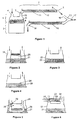
heater element 12 can be rated at a lower power than would otherwise be the case, as the gas already has a higher energy content and can tolerate a greater loss of energy before the gas condenses in thetube 12. It may even be possible to use an unheated, well insulated breathing circuit instead of a heated breathing circuit if the chamber provides gas with enough energy. Note that low relative humidity chambers can only be used if the heating to the chamber is controlled using an absolute humidity sensor, not a temperature sensor, since otherwise the absolute humidity output would be too low. - To this end, some humidification chamber configurations which provide a high temperature, low relative humidity gas output are shown in Figures 2 - 8. Figure 2 shows a chamber which incorporates a metal element 20 (e.g. a spiral scroll shape), but without wicking paper attached. This provides both dry heating (via the metal element) and heated humidification from the
heated water 21. With this configuration thechamber 19 provides gas which is not saturated because some of the heating provided to the gas is dry heating via the metal scroll. The relative humidity generated by the chamber is affected by the gas flow path, scroll shape, dimensions, and the water level, and so is not readily adjustable in use. Howeverchamber 19 does give the condensate reducing advantages provided by a low relative humidity, controlled absolute humidity output. - Figures 3 and 4 are alternative humidification chambers which provide low relative humidity, high temperature gases at their output. Figure 3 shows a chamber using a porous material 22 (such as a porous ceramic) containing water 23 to provide a heating and humidifying function, while Figure 4 shows a chamber using a
semipermeable membrane 24 to provide a barrier to thewater 25 in the chamber. In both cases these chambers provide dry heating via the porous or semipermeable material, as well as heated humidification from the water. In both cases the ratio of heating to humidifying is fixed and cannot be easily adjusted except by limiting the water supply. - Figures 5 to 8 show chambers that can supply gases at varying levels of relative humidity and temperature. In Figure 5 a
variable valve 26 allows us to adjust the ratio of gas which passes through thedry bypass tube 27 to that which flows across the surface of thewater 28. The bypass tube passes under the water to heat the gas. The two gas streams merge at theoutput 29. This is an example of a "parallel" system where the gas splits and takes two different paths to provide heating and humidification. In Figure 6 the gas is again split into two gas paths using anadjustable valve 30. One part of the gas gets humidified by passing across thewater 31 inchamber 32, while the other is heated byheater 58, which surroundstube 33. The gas paths merge atjunction 34. - The angle of
variable valves load valves springs - Figures 7 and 8 show alternative series configurations for low relative humidity chambers, where the dry
gas entering chamber 35 containingheated water 36 is either pre-heated viaheater 37 in Figure 7, or heated viaheater 38 in Figure 8 after leaving the chamber. In both cases the heater provides dry heating to the gas and results in a low relative humidity, high temperaturegas leaving outlet 39. - Any of the low relative humidity, high temperature chambers shown in Figures 2 to 8 can be used in conjunction with the humidity control schemes described previously in this patent, but not successfully with the prior art humidifier due to it being temperature controlled, not humidity controlled.
- Another facet of the invention is shown in Figure 9. Here the low relative humidity, high temperature humidification system from Figure 8 has been combined with an unheated, well insulated delivery tube. The incoming gas enters at
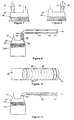
port 35 into thestandard humidification chamber 36 containingwater 37 which is heated byheater plate 38. The gas is substantially saturated in the chamber then leaves the chamber throughgas outlet 39 and entersheated tube section 40 which heats the humid gas to a higher temperature, so that it has a low relative humidity. The gas then passes throughtube 41 which has an insulatinglayer 42 around it. Preferably the insulating layer is a thin jacket of stagnant air which reduces heat loss. As the high temperature gas, low relative humidity gas passes through the insulating tube, a small amount of heat is lost through the tube walls, and therefore the gas cools. However the amount of heating applied toheater 40 is controlled, so that the gas is never allowed to cool below its dewpoint, which would result in condensation withintube 41. - Several different sensor configurations are proposed. Firstly,
sensor 43 could be an absolute humidity sensor which controlsheater plate 38 so thatchamber 36 produces the desired level of humidity. In oneembodiment sensor 45 is a temperature sensor, which controlsheater 40 so that thegas passing sensor 45 remains at a certain desired temperature. If this temperature is greater than the dewpoint of the gas atsensor 43, then condensation should not occur intube 41. However there may already be condensate intube 41 when the humidifier is turned on. If a humidity sensor is used forsensor 45 instead of a temperature sensor, then the level of condensate occurring in thetube 41 can be controlled. The algorithms described earlier in this patent for dual-humidity sensor control can be used with this system. - An alternative location for the absolute humidity sensor is at
position 44 instead of 43. The absolute humidity here should be the same as at 43 because the gas has been heated and so hasn't lost any moisture. However there may be advantages to placing the absolute humidity sensor at 44, for instance due to better sensor operation in a low relative humidity environment. This location for the absolute humidity sensor can be used with either a temperature or absolute humidity sensor atlocation 45. - Yet another aspect relates to removing the need for a sensor at the patient airway. To remove this sensor safely, we must be certain that the gas entering the delivery tube has a safe level of temperature and absolute humidity, and that the surfaces inside the delivery tube do not exceed safe temperature levels. This implies a delivery tube that has a constant internal wall temperature.
- It would be desirable, therefore, to have a heated delivery tube which self-regulates its temperature at a desired level. The heater could either be embedded in the wall of the delivery tube itself, or it could lie inside the lumen of the delivery tube, or it could be wrapped around the outside of the delivery tube. Such a heater could be made from positive temperature coefficient (PTC) material (such as "Winterguard" from Raychem Corp., Menlo Park, California USA), so that the resistance of the heater increases if the heater is hot, resulting in reduced power. However the delivery tube may pass through more than one environment, or may have localised drafts present on certain parts of the tube. If the PTC elements are arranged in parallel, then the full benefit of the PTC heater can be envisaged. If the PTC elements are arranged in parallel, then the cold portions of the tube will have a lower resistance, which will result in more heat being dissipated. Thus the tube will tend to regulate its own temperature.
- Figure 10 shows construction of a tube incorporating flexible PTC elements in a parallel wire configuration. The
tube 48 is made of a flexible PTC material, which has two low resistive strip connections, 46 and 47, on either side of it. This allows each portion of the tube to consist of short conducting segments of tube connected in parallel betweenconductors conductors adjustable voltage source 49, which may be AC or DC. The tube would have an outer layer (not shown) which provides electrical insulation and thermal insulation to the tube. Each longitudinal segment of the tube will be able to regulate its own temperature independently of the rest of the tube. To enhance this operation, it may be necessary to provideparallel slots 50 running perpendicular to the axis of the tube, to eliminate electrical cross-connection between the different PTC segments. - Although one specific PTC heated tube design has been envisaged and described, other PTC tube designs could be used. It may also be of advantage to create a PTC tube that has a differing temperature profile along its length rather than a constant temperature profile. The PTC design could also be extended to incorporate PTC heaters in other parts of the patient breathing circuit, such as the flexible extension tube which is usually connected between the Y-piece (
port 17 of Figure 1) and the patient's endotracheal tube. A further extension of the PTC tube concept would be into a self-heated and temperature controlled endotracheal tube. - The PTC tube described in Figure 10 allows us to create a humidifier which doesn't use any sensor at the patient airway. Figure 11 shows a humidifier configuration using this tube. Gas enters
humidification chamber 52 viainlet port 51 and is humidified bywater 53, heated byheater plate 54.Absolute humidity sensor 55 controls the heater plate so that thegas passing sensor 55 is at a desired level of absolute humidity.PTC tube 56 is heated by an external voltage (not shown) so that the internal surface temperature is at a constant desired temperature, which is selected to be above the dewpoint of the gas. The gas which leavestube 56 atoutlet 57 will therefore be near the temperature of the tube, and containing the desired level of absolute humidity which was controlled byabsolute humidity sensor 55. - A variation of the system shown in Figure 11 would be to use a temperature sensor at
position 55. Another variation of a tube with a constant internal wall temperature would a delivery tube with heated water or other fluid pumped through smaller conduits in the wall of the delivery tube. Since the heated fluid has a high specific heat relative to air, the temperature of the fluid remains fairly constant during passage through the delivery wall conduits. - Traditional humidifiers have tended to use sensors that are probe shaped, so that they can be inserted through specifically designed holes in the side of the breathing circuit to measure temperature. However the humidifier configurations that have been described in this patent incorporate many sensors around the chamber, so the use of a manifold 59 as shown in Figure 12 may be useful.
- The
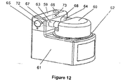
humidification chamber 60 is a removable item which can be slid onto thehumidifier base 61 as shown in Figure 12. As thechamber 60 is slid onto thehumidifier base 61, its base makes contact withheater plate 62 and its inlet andoutlet ports holes manifold 59. Dry air to be humidified enters the manifold atport 65, passes out of the manifold throughport 67, and flows throughport 63 into thechamber 60, where it is humidified. - After leaving
chamber 60 the humid gas passes throughchamber port 64 intomanifold port 68. Finally the humid gas leavesmanifold 59 throughport 66 and passes to the breathing circuit. - The manifold may be a separate, removable assembly, or it may be an integral part of the humidifier base. It may contain temperature sensors, humidity sensors, flow sensors, or a heater element. These would be located inside the manifold 59 at
positions chamber ports outlet port 64. One advantage of using a manifold is that many sensors or heaters can be combined in a single, cleanable assembly, rather than requiring separate probes which need to be plugged into the breathing circuit. This simplifies connection and setup for the user. Another advantage of a manifold is that the incoming dry gas temperature and flow rate can easily be measured without additional probes and connections. - Although absolute humidity sensors have been described with all of the different humidification schemes described in this patent, relative humidity sensors could also be used. This may involve slightly different control algorithms to the ones described in this patent. Alternatively, a relative humidity sensor could be combined with a temperature sensor. This allows the absolute humidity to be calculated from relative humidity and temperature, rather than being measured directly.
- All of the humidification schemes that have been previously described could be used with additional temperature sensors. These may provide additional benefits such as providing a safety backup in the event of a failed humidity sensor. Another benefit would be maintaining the temperature being delivered to the patient within certain limits so that the relative humidity is not too low, even though the absolute humidity was acceptable.
- Similarly it may be useful to measure the air flowrate through the humidifier, as this is an important parameter which affects humidifier control. Therefore flow sensors could be incorporated within any of the previously described systems. One useful prior art flow sensor construction would be to use a sensor based on heat loss from a hot element in the airstream. If a heated humidity sensor is used, the amount of heating that is required for the sensor to achieve temperature can be used to determine the gas flow rate.
- Infection control is a prime consideration when designing medical components. To prevent bacterial colonisation of the components in the humidification system, any parts which come in contact with the gas stream could be made out of antibacterial plastic. To prevent contamination of sensor probes, the probe ports could incorporate a disposable sheath which protects the probe from pathogens in the breathing circuit. This would be particularly applicable to temperature probes. In general humidity probes need to have contact with the gas stream so a disposable sheath would be inapplicable to humidity sensors, unless they worked on optical principles, or unless the sheath was made of water vapour permeable material, which did not allow the passage of pathogens. The protective sheath could be an integral part of a disposable breathing circuit.
Claims (14)
- A humidification apparatus for humidifying a gases flow to be supplied to a patient or other person in need of such gases comprising:humidification chamber means (1) and having an inlet (4) and an outlet (10) to allow said gases flow to pass through said humidification chamber means (1),chamber heating means (9) provided adjacent said humidification chamber means (1) and adapted to vaporise liquid water (6) in said humidification chamber means (1) in order to provide water vapour to said gases flow passing through said humidification chamber means (1),conduit (11) connected to said outlet (10) of said humidification chamber means (1) to convey said gases flow to said patient or other person in need of such gases,
control means to control said chamber heater means,
humidity sensing means (7, 8) configured to provide an indication of the absolute humidity of said gases flow, where said control means is configured or programmed to receive as inputs said indication of the absolute humidity of said gases flow,
said humidity sensing means are configured to provide an indication of the absolute humidity of said gases flow at least at one of said humidification chamber means and at a point along said conduit in said gases flow, and
said control means are configured or programmed to estimate a rate of condensation of said gases in said conduit based on said inputs and control said chamber heating means based on said rate of condensation to minimise condensation of gases in said conduit. - A humidification apparatus as claimed in claim 1 wherein said conduit includes conduit heating means to heat said gases flow, and said control means is configured to control said conduit heater based on said rate of condensation to minimise condensation of said gases in said conduit (11).
- A humidification apparatus as claimed in claim 2 wherein said humidity sensing means including a first absolute humidity sensor (7) in substantial proximity to said outlet (10) of said humidification chamber means (1).
- A humidification apparatus as claimed in claim 3 wherein said conduit (11) having a patient end (5), distal to said end connected to said outlet (10) of said humidification chamber means (1), and said humidity sensing means further comprising a second absolute humidity sensor (8) in substantial proximity to said patient end (5) of said conduit (2).
- A humidification apparatus as claimed in claim 4 wherein said estimate of the rate of condensation is based on the difference between the absolute humidity at said outlet (10) of said humidification chamber means (1), as indicated by the output of said first absolute humidity sensor (7), and the absolute humidity at said patient end (5) of said conduit (11), as indicated by the output of said second absolute humidity sensor (8).
- A humidification apparatus as claimed in claim 5 wherein said control means is configured to:i) energise said conduit heating means (12) depending on at least said estimate of the rate of condensation, to a level appropriate to substantially vaporise any liquid condensate present in said conduit (11); andii) energise said conduit heating means (12) depending on at least said estimate of the rate of condensation, to a level appropriate to minimise any condensation of the vapour from said gases in said conduit (11).
- A humidification apparatus as claimed in claim 6 wherein said steps (i) and (ii) are repeated continually at regular intervals.
- A humidification apparatus as claimed in claim 6 wherein said steps (i) and (ii) are alternated at regular intervals.
- A humidification apparatus as claimed in claim 2 wherein said conduit (11) having a patient end (5), distal to said end connected to said outlet (10) of said humidification chamber means (1)and said apparatus further comprising a first temperature sensor (7) in substantial proximity to said outlet (10) of said humidification chamber means (1) and an absolute humidity sensor (8) in substantial proximity to said patient end (5) of said conduit (11).
- A humidification apparatus as claimed in claim 2 further comprising at least a temperature sensor and at least one relative humidity sensor providing an indication of the temperature and relative humidity at least at one point in the flow path of said gases flow through said apparatus.
- A humidification apparatus as claimed in claim 2 wherein further comprising flow sensing means adapted to provide an indication of the rate of flow of said gases flown through said apparatus.
- A humidification apparatus as claimed in claim 11 wherein said flow sensing means comprising a heated element adapted to maintain a substantially constant temperature and being provided in the flow path of said gases through said apparatus, the heat loss therefrom providing an indication of the rate of flow of said gases.
- A humidification apparatus as claimed in claims 1 or 2 wherein said humidity sensing means further comprising a disposable cover means for providing porous material as a substantial barrier to microorganisms between said flow of gases and said humidity sensor.
- A humidification apparatus as claimed in claims 1 or 2 wherein said humidity sensing means (7, 8) further comprising porous disposable cover means for providing porous material as a substantial barrier to microorganisms between said flow of gases and said humidity sensing means (7, 8).
Priority Applications (4)
| Application Number | Priority Date | Filing Date | Title |
|---|---|---|---|
| EP04028254A EP1522326B1 (en) | 2000-03-21 | 2001-03-19 | Breathing assistance apparatus |
| EP07001891A EP1790370A1 (en) | 2000-03-21 | 2001-03-19 | Humidification apparatus |
| EP07001892A EP1790371B1 (en) | 2000-03-21 | 2001-03-19 | Humidification apparatus |
| EP06006595A EP1681072B1 (en) | 2000-03-21 | 2001-03-19 | Breathing assistance apparatus |
Applications Claiming Priority (2)
| Application Number | Priority Date | Filing Date | Title |
|---|---|---|---|
| NZ50349500 | 2000-03-21 | ||
| NZ50349500 | 2000-03-21 |
Related Child Applications (3)
| Application Number | Title | Priority Date | Filing Date |
|---|---|---|---|
| EP06006595A Division EP1681072B1 (en) | 2000-03-21 | 2001-03-19 | Breathing assistance apparatus |
| EP07001891A Division EP1790370A1 (en) | 2000-03-21 | 2001-03-19 | Humidification apparatus |
| EP04028254A Division EP1522326B1 (en) | 2000-03-21 | 2001-03-19 | Breathing assistance apparatus |
Publications (3)
| Publication Number | Publication Date |
|---|---|
| EP1138341A2 EP1138341A2 (en) | 2001-10-04 |
| EP1138341A3 EP1138341A3 (en) | 2003-08-13 |
| EP1138341B1 true EP1138341B1 (en) | 2006-06-28 |
Family
ID=19927797
Family Applications (5)
| Application Number | Title | Priority Date | Filing Date |
|---|---|---|---|
| EP04028254A Expired - Lifetime EP1522326B1 (en) | 2000-03-21 | 2001-03-19 | Breathing assistance apparatus |
| EP06006595A Expired - Lifetime EP1681072B1 (en) | 2000-03-21 | 2001-03-19 | Breathing assistance apparatus |
| EP07001891A Withdrawn EP1790370A1 (en) | 2000-03-21 | 2001-03-19 | Humidification apparatus |
| EP01106827A Expired - Lifetime EP1138341B1 (en) | 2000-03-21 | 2001-03-19 | Humidification apparatus |
| EP07001892A Expired - Lifetime EP1790371B1 (en) | 2000-03-21 | 2001-03-19 | Humidification apparatus |
Family Applications Before (3)
| Application Number | Title | Priority Date | Filing Date |
|---|---|---|---|
| EP04028254A Expired - Lifetime EP1522326B1 (en) | 2000-03-21 | 2001-03-19 | Breathing assistance apparatus |
| EP06006595A Expired - Lifetime EP1681072B1 (en) | 2000-03-21 | 2001-03-19 | Breathing assistance apparatus |
| EP07001891A Withdrawn EP1790370A1 (en) | 2000-03-21 | 2001-03-19 | Humidification apparatus |
Family Applications After (1)
| Application Number | Title | Priority Date | Filing Date |
|---|---|---|---|
| EP07001892A Expired - Lifetime EP1790371B1 (en) | 2000-03-21 | 2001-03-19 | Humidification apparatus |
Country Status (10)
| Country | Link |
|---|---|
| US (6) | US6918389B2 (en) |
| EP (5) | EP1522326B1 (en) |
| JP (5) | JP4386595B2 (en) |
| CN (4) | CN102580219B (en) |
| AT (4) | ATE465766T1 (en) |
| AU (1) | AU784172B2 (en) |
| CA (4) | CA2617234C (en) |
| DE (4) | DE60141995D1 (en) |
| ES (2) | ES2266038T3 (en) |
| HK (1) | HK1089115A1 (en) |
Cited By (1)
| Publication number | Priority date | Publication date | Assignee | Title |
|---|---|---|---|---|
| US8851071B2 (en) | 2007-08-08 | 2014-10-07 | Dräger Medical GmbH | Respiration humidifier |
Families Citing this family (196)
| Publication number | Priority date | Publication date | Assignee | Title |
|---|---|---|---|---|
| JP4695318B2 (en) | 1999-08-05 | 2011-06-08 | エムアーペー メディツィンテクノロジー ゲゼルシャフト・ミット・ベシュレンクテル・ハフツング | Apparatus for supplying exhaled gas, humidifier, breathing tube connection device, breathing tube and connection structure |
| US6918389B2 (en) | 2000-03-21 | 2005-07-19 | Fisher & Paykel Healthcare Limited | Breathing assistance apparatus |
| US7111624B2 (en) | 2000-03-21 | 2006-09-26 | Fisher & Paykel Healthcare Limited | Apparatus for delivering humidified gases |
| US7120354B2 (en) | 2000-03-21 | 2006-10-10 | Fisher & Paykel Healthcare Limited | Gases delivery conduit |
| US7588029B2 (en) * | 2000-03-21 | 2009-09-15 | Fisher & Paykel Healthcare Limited | Humidified gases delivery apparatus |
| JP4180367B2 (en) | 2000-10-16 | 2008-11-12 | フィッシャー アンド ペイケル ヘルスケア リミテッド | Equipment used for humidifying gases in medical procedures |
| US7708013B2 (en) | 2000-12-08 | 2010-05-04 | Vapotherm, Inc. | Apparatus and method for delivering water vapor to a gas |
| US6935337B2 (en) | 2001-02-16 | 2005-08-30 | Resmed Limited | Humidifier with structure to prevent backflow of liquid through the humidifier inlet |
| DE10139881B4 (en) * | 2001-08-20 | 2017-06-08 | Resmed R&D Germany Gmbh | Apparatus for supplying a breathing gas and method for controlling the same |
| EP1295621B1 (en) * | 2001-09-19 | 2018-11-07 | Fisher & Paykel Healthcare Limited | Humidified gases delivery apparatus |
| JP4401287B2 (en) * | 2002-05-29 | 2010-01-20 | ベーフェーベーアー・メディシーゼ・ベルギー | Respiratory heating humidifier |
| AU2003237692A1 (en) * | 2002-05-29 | 2003-12-12 | Jean-Michel Anthony | Device for heating and moistening a breathing gas |
| EP1542756B1 (en) * | 2002-08-30 | 2016-10-19 | Fisher & Paykel Healthcare Limited | Humidification system |
| DE19212475T1 (en) * | 2002-09-17 | 2020-05-28 | Fisher & Paykel Healthcare Limited | HUMIDIFIED GAS DELIVERY DEVICE |
| DE10318383B3 (en) * | 2003-04-23 | 2004-07-01 | Dräger Medical AG & Co. KGaA | Breathing gas moisturizer for CPAP breathing apparatus has evaporator in side branch from inspiration line and has temperature and humidity sensors connected to control circuit |
| NZ585683A (en) * | 2003-06-20 | 2011-12-22 | Resmed Ltd | Breathable gas apparatus with humidifier |
| AU2003903139A0 (en) * | 2003-06-20 | 2003-07-03 | Resmed Limited | Breathable gas apparatus with humidifier |
| DK1656173T3 (en) * | 2003-08-20 | 2016-04-11 | Fisher & Paykel Healthcare Ltd | Humidifier water chamber |
| US7396995B2 (en) * | 2003-09-19 | 2008-07-08 | Fisher & Paykel Healthcare Limited | Connector |
| ES2564979T3 (en) * | 2003-12-15 | 2016-03-30 | Teijin Pharma Limited | Humidification device and oxygen concentration system |
| DE102004037823A1 (en) * | 2004-08-04 | 2006-03-16 | Viasys Healthcare Gmbh | Evaporator, ventilator and evaporation process |
| NZ553013A (en) * | 2004-08-10 | 2010-12-24 | Resmed Ltd | Method and apparatus for humidification of breathable gas with profiled varying humidity setting delivery |
| EP4049703B1 (en) | 2004-08-20 | 2023-09-27 | Fisher & Paykel Healthcare Limited | Apparatus for measuring properties of gases supplied to a patient |
| FR2875138B1 (en) | 2004-09-15 | 2008-07-11 | Mallinckrodt Dev France Sa | CONTROL METHOD FOR A HEATING HUMIDIFIER |
| US7428902B2 (en) * | 2004-12-15 | 2008-09-30 | Newport Medical Instruments, Inc. | Humidifier system for artificial respiration |
| DE102005000690B3 (en) * | 2005-01-04 | 2006-05-11 | Dräger Medical AG & Co. KG | Artificial ventilation humidifier for use in active humidification system, has evaporator that has non-heated region made of porous glass or ceramic sinter at lower portion and heated region made of porous metal sinter at upper portion |
| AU2006250091B2 (en) | 2005-05-26 | 2009-07-23 | Fisher & Paykel Healthcare Limited | Breathing assistance apparatus |
| JP4990891B2 (en) | 2005-07-01 | 2012-08-01 | フィッシャー アンド ペイケル ヘルスケア リミテッド | Respiratory support device with manifold for adding auxiliary gas to ambient gas |
| US8640696B2 (en) * | 2005-07-07 | 2014-02-04 | Ric Investments Llc | System and method for determining humidity in a respiratory treatment system |
| EP1924312B1 (en) | 2005-08-15 | 2016-06-29 | ResMed Limited | Humidifier tub for cpap device |
| CN101242867B (en) | 2005-08-15 | 2011-05-18 | 雷斯梅德有限公司 | Humidifier and/or flow generator for CPAP device |
| US8739780B2 (en) | 2005-08-15 | 2014-06-03 | Resmed Limited | Low cost CPAP flow generator and humidifier assembly |
| US7677246B2 (en) * | 2005-09-23 | 2010-03-16 | Ric Investments, Llc | Modular pressure support system |
| US8997740B2 (en) * | 2005-09-27 | 2015-04-07 | Ric Investments, Llc | Humidifier with back-flow prevention valve |
| US8701662B2 (en) * | 2005-09-27 | 2014-04-22 | Ric Investments, Llc | Humidifier with back-flow prevention valve |
| JP5340739B2 (en) * | 2005-12-01 | 2013-11-13 | ハイドレイト、インコーポレイテッド | Inline vaporizer |
| CN103463722B (en) | 2005-12-15 | 2015-12-09 | 菲舍尔和佩克尔保健有限公司 | Respiratory assistance apparatus |
| DE102006006183A1 (en) * | 2006-02-10 | 2007-08-16 | Pari GmbH Spezialisten für effektive Inhalation | Inhalation therapy device for use in premature babies and toddlers |
| US7913985B2 (en) * | 2006-03-09 | 2011-03-29 | Invacare Corporation | Cap |
| US8074645B2 (en) | 2006-04-10 | 2011-12-13 | Somnetics Global Pte. Ltd. | Apparatus and methods for providing humidity in respiratory therapy |
| JP2008006067A (en) * | 2006-06-29 | 2008-01-17 | Senko Medical Instr Mfg Co Ltd | Temperature adjusting structure of temperature/humidity exchanger for respiration, and jacket used for the same |
| JP5019156B2 (en) * | 2006-08-21 | 2012-09-05 | ウシオ電機株式会社 | Excimer lamp device |
| JP5009989B2 (en) * | 2006-08-25 | 2012-08-29 | フィッシャー アンド ペイケル ヘルスケア リミテッド | Humidifier with internal heating element and heater plate |
| JP5443991B2 (en) | 2006-11-08 | 2014-03-19 | レスメド・リミテッド | Conduit for use in respiratory equipment |
| CN101541367B (en) * | 2006-11-08 | 2014-02-26 | 雷斯梅德有限公司 | Conduit for use in a respiratory apparatus |
| WO2008060587A2 (en) * | 2006-11-15 | 2008-05-22 | Vapotherm, Inc. | Nasal cannula with reduced heat loss to reduce rainout |
| CN101220988B (en) * | 2007-01-12 | 2010-09-29 | 雃博股份有限公司 | Warming disk assembly of respiration therapeutic equipment |
| AU2008208148B2 (en) * | 2007-01-23 | 2014-04-17 | Fisher & Paykel Healthcare Limited | Humidification apparatus having RFID tag sensor at patient end of gas pathway |
| DE102007015038B3 (en) * | 2007-02-08 | 2008-03-27 | Dräger Medical AG & Co. KG | Device for preparing respiration gas, uses control device for determining temperature of output gas at given desired moisture level |
| US8944056B2 (en) * | 2007-02-09 | 2015-02-03 | Resmed Limited | Humidification arrangement for a respiratory apparatus |
| DE102007011544B3 (en) * | 2007-03-09 | 2008-06-05 | Dräger Medical AG & Co. KG | Breathing moistener controlling method, involves adjusting output of dampness of gas, where measured electrical resistance or capacitance lies as measure of dew of gas, in preset desired value range with maximum and minimum values |
| US8365726B2 (en) | 2007-06-07 | 2013-02-05 | Resmed Limited | Tub for humidifier |
| US8550075B2 (en) * | 2007-06-28 | 2013-10-08 | Resmed Limited | Removable and/or replaceable humidifier |
| ITMI20071347A1 (en) * | 2007-07-06 | 2009-01-07 | Fabrizio Cattaneo | INHALATION DEVICE FOR RESPIRATORY ADMINISTRATION OF MEDICATIONS IN GENERAL. |
| US8677993B2 (en) * | 2007-07-18 | 2014-03-25 | Vapotherm, Inc. | Humidifier for breathing gas heating and humidification system |
| CN101808689B (en) * | 2007-08-14 | 2013-10-09 | 柔性塑料集团 | A respiratory system |
| DE102007039391B4 (en) * | 2007-08-21 | 2016-06-09 | Drägerwerk AG & Co. KGaA | respiratory humidifier |
| US8196579B2 (en) * | 2007-08-29 | 2012-06-12 | Smiths Medical Asd, Inc. | Nose cannula heated/humidified gas delivery system |
| US8905023B2 (en) | 2007-10-05 | 2014-12-09 | Vapotherm, Inc. | Hyperthermic humidification system |
| US8049143B2 (en) * | 2007-10-29 | 2011-11-01 | Smiths Medical Asd, Inc. | Hot plate heater for a respiratory system |
| US7983542B2 (en) * | 2007-10-29 | 2011-07-19 | Smiths Medical Asd, Inc. | PID coefficient adjustment for respiratory heater closed loop control |
| US7777635B2 (en) * | 2007-10-29 | 2010-08-17 | Smiths Medical Asd, Inc. | Power failure management for respiratory system heater unit |
| US8122882B2 (en) * | 2007-10-29 | 2012-02-28 | Smiths Medical Asd, Inc. | Rainout reduction in a breathing circuit |
| US8059947B2 (en) * | 2007-10-29 | 2011-11-15 | Smiths Medical Asd, Inc. | Environmentally protected thermistor for respiratory system |
| US8772681B2 (en) * | 2007-11-15 | 2014-07-08 | Electronic Instrumentation And Technology, Inc. | Method and apparatus for forced air heater measurement and control |
| ES2391595T3 (en) * | 2008-02-18 | 2012-11-28 | Covidien Ag | Device for detecting relative humidity in a respiratory circuit |
| BRPI0908524A2 (en) * | 2008-02-26 | 2015-09-29 | Konink Philips Eletronics N V | pressure support system, and method for providing a humidified breathing gas flow |
| US9802022B2 (en) | 2008-03-06 | 2017-10-31 | Resmed Limited | Humidification of respiratory gases |
| US8361801B2 (en) * | 2008-04-14 | 2013-01-29 | Deka Products Limited Partnership | Devices, systems, and methods for aiding in the detection of a physiological abnormality |
| DE102008022663B4 (en) | 2008-05-07 | 2012-10-31 | Schauenburg Hose Technology Gmbh | Stretch hose |
| US9505164B2 (en) | 2009-12-30 | 2016-11-29 | Schauenburg Technology Se | Tapered helically reinforced hose and its manufacture |
| AU2009251939B2 (en) * | 2008-05-27 | 2015-08-06 | Fisher & Paykel Healthcare Limited | Control of humidifier chamber temperature for accurate humidity control |
| US20090301476A1 (en) * | 2008-06-05 | 2009-12-10 | Neil Alex Korneff | Heat and moisture exchange unit |
| NZ742900A (en) | 2008-06-05 | 2020-02-28 | ResMed Pty Ltd | Treatment of respiratory conditions by automatic control of flow and/or temperature and/or humidity independently to nares via separate flow paths |
| US8561606B2 (en) * | 2008-06-05 | 2013-10-22 | Carefusion 2200, Inc. | Heat and moisture exchange unit |
| US20090301477A1 (en) * | 2008-06-05 | 2009-12-10 | Brian William Pierro | Heat and moisture exchange unit with check valve |
| WO2010016838A1 (en) | 2008-08-06 | 2010-02-11 | Ric Investments, Llc | System and method for determining humidity in a respiratory treatment system |
| CN109481813B (en) | 2008-09-17 | 2022-01-11 | 瑞思迈私人有限公司 | A case and humidifier for inserting into humidifier chamber |
| CA2743776A1 (en) * | 2008-12-05 | 2010-06-10 | Philip Morris Products S.A. | Apparatus and method for treatment of gaseous material |
| US9964238B2 (en) | 2009-01-15 | 2018-05-08 | Globalmed, Inc. | Stretch hose and hose production method |
| US20100242961A1 (en) * | 2009-03-31 | 2010-09-30 | Nellcor Puritan Bennett Llc | Systems and methods for preventing water damage in a breathing assistance system |
| US8539948B2 (en) | 2009-05-19 | 2013-09-24 | William Beaumont Hospital | Hyperthermia assisted radiation therapy |
| US20100300446A1 (en) * | 2009-05-26 | 2010-12-02 | Nellcor Puritan Bennett Llc | Systems and methods for protecting components of a breathing assistance system |
| US8931481B2 (en) | 2009-06-04 | 2015-01-13 | Redmed Limited | Flow generator chassis assembly with suspension seal |
| AU2010206053B2 (en) | 2009-07-31 | 2014-08-07 | ResMed Pty Ltd | Wire Heated Tube with Temperature Control System, Tube Type Detection, and Active Over Temperature Protection for Humidifier for Respiratory Apparatus |
| DE102009038635B4 (en) * | 2009-08-26 | 2015-02-19 | F. Stephan Gmbh Medizintechnik | Device for breathing gas humidification |
| WO2011030251A1 (en) * | 2009-09-11 | 2011-03-17 | Koninklijke Philips Electronics N.V. | Humidifier with wireless temperature sensing |
| US20110108031A1 (en) * | 2009-11-11 | 2011-05-12 | Carefusion 2200 Inc. | Heated conduit for respiratory humidification |
| JP2011125618A (en) * | 2009-12-21 | 2011-06-30 | Pacific Medico Co Ltd | Heating/humidifying apparatus for artificial respirator |
| WO2011078701A1 (en) | 2009-12-23 | 2011-06-30 | Fisher & Paykel Healthcare Limited | Improvements relating to systems for laparoscopic surgery |
| CN104888330B (en) * | 2009-12-23 | 2019-01-08 | 费雪派克医疗保健有限公司 | Humidified gases delivery apparatus and its control method |
| JP5995289B2 (en) * | 2010-04-27 | 2016-09-21 | フィッシャー アンド ペイケル ヘルスケア リミテッド | Water out alarm |
| CN103037928B (en) * | 2010-04-27 | 2016-10-12 | 费雪派克医疗保健有限公司 | For supplying the device of gas to patient |
| WO2011151741A1 (en) * | 2010-06-04 | 2011-12-08 | Koninklijke Philips Electronics N.V. | Automatic humidity control in a pressure support system |
| EA201300255A1 (en) | 2010-08-23 | 2013-06-28 | Такеда Гмбх | MOUNTED PARTICLES, CONTAINING A THERAPEUTICALLY ACTIVE SUBSTANCE |
| WO2012025846A1 (en) * | 2010-08-27 | 2012-03-01 | Koninklijke Philips Electronics N.V. | Portable humidification system and adaptor therefore |
| WO2012031315A1 (en) * | 2010-09-06 | 2012-03-15 | Resmed Limited | Methods and apparatus for preventing rainout |
| US20120060836A1 (en) * | 2010-09-10 | 2012-03-15 | Michael El-Shammaa | Patient circuit for improved support delivery |
| CN103167891B (en) * | 2010-10-21 | 2016-04-20 | 皇家飞利浦电子股份有限公司 | Humidifier bypass valve |
| NZ716600A (en) | 2010-11-15 | 2017-08-25 | Resmed Humidification Tech Gmbh | Methods and devices in the field of treatment with medical gases |
| US9314582B2 (en) | 2010-11-23 | 2016-04-19 | Carefusion 2200, Inc. | Humidification system |
| AU2012211031B2 (en) * | 2011-01-24 | 2015-04-23 | ResMed Pty Ltd | Humidifier |
| US8511651B2 (en) | 2011-03-29 | 2013-08-20 | Smiths Medical Asd, Inc. | Heater unit humidification chamber monitor |
| US10080866B2 (en) | 2011-06-03 | 2018-09-25 | Fisher & Paykel Healthcare Limited | Medical tubes and methods of manufacture |
| US9038634B2 (en) | 2011-06-22 | 2015-05-26 | Breathe Technologies, Inc. | Ventilation mask with integrated piloted exhalation valve |
| US9486602B2 (en) | 2011-06-22 | 2016-11-08 | Breathe Technologies, Inc. | Ventilation mask with integrated piloted exhalation valve and method of ventilating a patient using the same |
| US8839791B2 (en) | 2011-06-22 | 2014-09-23 | Breathe Technologies, Inc. | Ventilation mask with integrated piloted exhalation valve |
| US10010693B2 (en) | 2011-06-28 | 2018-07-03 | Fisher & Paykel Healthcare Limited | Medical tubing |
| US8733348B2 (en) | 2011-09-30 | 2014-05-27 | Carefusion 207, Inc. | Humidifying respiratory gases |
| US9205220B2 (en) | 2011-09-30 | 2015-12-08 | Carefusion 207, Inc. | Fluted heater wire |
| US10168046B2 (en) | 2011-09-30 | 2019-01-01 | Carefusion 207, Inc. | Non-metallic humidification component |
| US9212673B2 (en) * | 2011-09-30 | 2015-12-15 | Carefusion 207, Inc. | Maintaining a water level in a humidification component |
| EP2817058B1 (en) | 2012-02-24 | 2016-06-29 | Koninklijke Philips N.V. | Rainout protection for respiratory therapy including humidification |
| CN104144723A (en) * | 2012-03-01 | 2014-11-12 | 皇家飞利浦有限公司 | Method and apparatus for determining a liquid level in a humidified pressure support device |
| WO2013137753A1 (en) * | 2012-03-15 | 2013-09-19 | Fisher & Paykel Healthcare Limited | Respiratory gas humidification system |
| US9272113B2 (en) | 2012-03-30 | 2016-03-01 | Carefusion 207, Inc. | Transporting liquid in a respiratory component |
| EP3998097A1 (en) | 2012-04-05 | 2022-05-18 | Fisher & Paykel Healthcare Limited | Respiratory assistance apparatus |
| GB2577634B (en) | 2012-04-27 | 2020-09-30 | Fisher & Paykel Healthcare Ltd | Respiratory humidification apparatus |
| GB2504076A (en) | 2012-07-16 | 2014-01-22 | Nicoventures Holdings Ltd | Electronic smoking device |
| US10300236B2 (en) | 2012-10-31 | 2019-05-28 | Vapotherm, Inc. | Quiet nasal cannula |
| CH707162A1 (en) * | 2012-11-06 | 2014-05-15 | Condair Ag | Evaporation apparatus. |
| CN104955510B (en) * | 2012-11-14 | 2017-05-10 | 费雪派克医疗保健有限公司 | Zone heating for respiratory circuits |
| WO2014088430A1 (en) * | 2012-12-04 | 2014-06-12 | Fisher & Paykel Healthcare Limited | Medical tubes and methods of manufacture |
| CN102989077B (en) * | 2012-12-13 | 2014-12-24 | 王路维 | Humidity-adjustable noise-free oxygen humidifying device |
| US10314989B2 (en) | 2013-01-28 | 2019-06-11 | Hancock Medical, Inc. | Position control devices and methods for use with positive airway pressure systems |
| NZ743034A (en) | 2013-02-01 | 2019-12-20 | ResMed Pty Ltd | Wire heated tube with temperature control system for humidifier for respiratory apparatus |
| US9878121B2 (en) | 2013-03-13 | 2018-01-30 | Breathe Technologies, Inc. | Ventilation mask with heat and moisture exchange device |
| TWI626962B (en) | 2013-03-15 | 2018-06-21 | 澳大利亞商瑞思邁有限公司 | Humidifier reservoir, an apparatus for humidifying and a method of preventing overfilling |
| CA3093754A1 (en) * | 2013-03-15 | 2014-09-18 | Fisher & Paykel Healthcare Limited | Components for medical circuits |
| WO2014142679A1 (en) * | 2013-03-15 | 2014-09-18 | Fisher & Paykel Healthcare Limited | Drying expiratory limb with tailored temperature profile and multi-lumen configuration |
| US9861778B2 (en) | 2013-03-15 | 2018-01-09 | Resmed Limited | Humidifier reservoir |
| KR20150133807A (en) * | 2013-03-23 | 2015-11-30 | 라이노케어 엘티디 | Systems and methods of preparing a controlled mixture for hyperthermal treatment |
| US9561341B2 (en) * | 2013-05-17 | 2017-02-07 | Katarina Short | Humidification of ventilator gases |
| CN105764560B (en) * | 2013-09-13 | 2018-04-06 | 费雪派克医疗保健有限公司 | Connection for humidification system |
| CA3176048A1 (en) | 2013-09-13 | 2015-03-19 | Fisher And Paykel Healthcare Limited | Humidification system |
| US10814091B2 (en) | 2013-10-24 | 2020-10-27 | Fisher & Paykel Healthcare Limited | System for delivery of respiratory gases |
| US20150165146A1 (en) | 2013-12-17 | 2015-06-18 | Bruce Bowman | Humidification system and positive airway pressure apparatus incorporating same |
| BR122017027113B1 (en) | 2013-12-20 | 2022-07-19 | Fisher & Paykel Healthcare Limited | CIRCUIT CONNECTOR FOR HUMIDIFICATION SYSTEM, BASE UNIT AND CONDUIT |
| US10449319B2 (en) | 2014-02-07 | 2019-10-22 | Fisher & Paykel Healthcare Limited | Respiratory humidification system |
| CN111481797B (en) | 2014-03-13 | 2023-03-21 | 瑞思迈私人有限公司 | Humidifier for respiratory therapy device |
| JP6731398B2 (en) | 2014-03-17 | 2020-07-29 | フィッシャー アンド ペイケル ヘルスケア リミテッド | Medical tubing for respiratory system |
| US11173272B2 (en) | 2014-05-02 | 2021-11-16 | Fisher & Paykel Healthcare Limited | Gas humidification arrangement |
| CN110124174A (en) | 2014-05-13 | 2019-08-16 | 费雪派克医疗保健有限公司 | Availability aspect for breathing humidification system |
| CN106535972B (en) | 2014-05-27 | 2019-09-03 | 费雪派克医疗保健有限公司 | Gas mixing and measurement for medical device |
| US11324911B2 (en) | 2014-06-03 | 2022-05-10 | Fisher & Paykel Healthcare Limited | Flow mixers for respiratory therapy systems |
| EP3498325B1 (en) * | 2014-06-10 | 2022-01-12 | Stamford Devices Limited | An aerosol delivery system with humidification |
| EP3166671B1 (en) * | 2014-07-10 | 2019-09-04 | Fisher & Paykel Healthcare Limited | Metal-organic framework materials in gases delivery systems |
| GB2528673B (en) * | 2014-07-25 | 2020-07-01 | Nicoventures Holdings Ltd | Aerosol provision system |
| WO2016028525A1 (en) | 2014-08-18 | 2016-02-25 | Hancock Medical, Inc. | Portable pap device with humidification |
| TWI785521B (en) * | 2014-09-03 | 2022-12-01 | 紐西蘭商費雪派克保健有限公司 | Respiratory humidification system, heater element for the system and method to deterministically deliver gases |
| US9649468B2 (en) | 2014-09-03 | 2017-05-16 | Fisher & Paykel Healthcare Limited | Respiratory gas humidifier |
| US11278689B2 (en) | 2014-11-17 | 2022-03-22 | Fisher & Paykel Healthcare Limited | Humidification of respiratory gases |
| CN107106830B (en) * | 2014-11-25 | 2022-01-11 | 费雪派克医疗保健有限公司 | Substance delivery device for a gas treatment apparatus |
| AU2015360692B2 (en) | 2014-12-09 | 2020-07-02 | Flexicare, Inc. | Systems and methods for heating and humidifying inspired gases during mechanical ventilation |
| US10596345B2 (en) | 2014-12-31 | 2020-03-24 | Vapotherm, Inc. | Systems and methods for humidity control |
| JP2016123744A (en) * | 2015-01-06 | 2016-07-11 | アトムメディカル株式会社 | Heating and humidifying device for respiratory gas and jacket heater |
| WO2016139645A1 (en) | 2015-03-05 | 2016-09-09 | Resmed Limited | A humidifier for a respiratory therapy device |
| US10398871B2 (en) | 2015-03-31 | 2019-09-03 | Vapotherm, Inc. | Systems and methods for patient-proximate vapor transfer for respiratory therapy |
| CN104784800A (en) * | 2015-04-23 | 2015-07-22 | 刘茹涵 | Breathing long tube heating device having automatic temperature control function |
| JP2018514301A (en) | 2015-04-27 | 2018-06-07 | テレフレックス メディカル インコーポレイテッド | Humidification device |
| AU2016203593B1 (en) * | 2015-06-02 | 2016-11-10 | Roger Foote | Medical humidifier |
| TWI720015B (en) | 2015-09-09 | 2021-03-01 | 紐西蘭商費雪派克保健有限公司 | Zone heating for respiratory circuits |
| DE102015119523B4 (en) * | 2015-11-12 | 2024-02-22 | Wilamed Gmbh | Ventilation circuit |
| WO2017095241A2 (en) | 2015-12-02 | 2017-06-08 | Fisher & Paykel Healthcare Limited | Flow path sensing for flow therapy apparatus |
| EP4169561A1 (en) * | 2015-12-11 | 2023-04-26 | Fisher & Paykel Healthcare Limited | Humidification system |
| US11305089B2 (en) | 2016-04-13 | 2022-04-19 | Metran Co., Ltd. | Humidifier and respiratory assistance device |
| CN105664321A (en) * | 2016-04-25 | 2016-06-15 | 湖南明康中锦医疗科技发展有限公司 | Control device of respirator |
| CN109310348B (en) | 2016-05-19 | 2022-01-25 | 汉考克医药公司 | Posture obstructive sleep apnea detection system |
| CN106178220B (en) * | 2016-07-12 | 2019-02-22 | 湖南明康中锦医疗科技发展有限公司 | A kind of ventilator condensation-proof control system and method |
| CN213642639U (en) | 2016-10-14 | 2021-07-09 | 蒸汽热能公司 | System for fluid circulation in a respiratory therapy unit and vapor transfer system |
| CN106267498B (en) * | 2016-10-26 | 2018-11-27 | 广西大学 | Infiltration type humidification heating electric pulmotor |
| WO2018081272A1 (en) | 2016-10-26 | 2018-05-03 | Teleflex Medical Incorporated | System and method for on-demand near-patient humidification |
| CN106288299B (en) * | 2016-10-31 | 2022-04-12 | 广东美的制冷设备有限公司 | System for preventing water vapor condensation and control method |
| WO2018106126A1 (en) | 2016-12-07 | 2018-06-14 | Fisher And Paykel Healthcare Limited | Sensing arrangements for medical devices |
| EP3544662A4 (en) * | 2016-12-22 | 2020-07-29 | Fisher & Paykel Healthcare Limited | Medical tubes and methods of manufacture |
| US10768160B2 (en) * | 2017-01-12 | 2020-09-08 | Regents Of The University Of Minnesota | Artificial gut simulator and method |
| EP3565700A4 (en) | 2017-01-30 | 2020-01-15 | GlobalMed, Inc. | Heated respiratory hose assembly |
| WO2019043110A1 (en) * | 2017-09-01 | 2019-03-07 | Koninklijke Philips N.V. | A mask-based breathing apparatus and control method |
| CN108245759A (en) * | 2017-12-16 | 2018-07-06 | 湖南明康中锦医疗科技发展有限公司 | Breathe humidification instrument humiture output control system and method |
| CN108283753A (en) * | 2017-12-16 | 2018-07-17 | 湖南明康中锦医疗科技发展有限公司 | Breathe humidification instrument anti-dry detecting system and method |
| US11338105B2 (en) | 2018-03-27 | 2022-05-24 | Globalmed, Inc. | Respiratory humidification device |
| CN108619601B (en) * | 2018-05-04 | 2021-06-08 | 东莞永胜医疗制品有限公司 | Heating pipe for respiratory system, respiratory system and control method of respiratory system |
| CN112135653A (en) | 2018-05-14 | 2020-12-25 | 柯惠有限合伙公司 | System and method for ventilation humidification |
| EP3586897A1 (en) | 2018-06-29 | 2020-01-01 | Koninklijke Philips N.V. | Humidifier for a system for providing a flow of breathable gas |
| US11071842B2 (en) | 2018-07-09 | 2021-07-27 | Perma Pure Llc | Low-flow oxygen therapy humidifier and method |
| US20200016360A1 (en) * | 2018-07-11 | 2020-01-16 | Martin Allan Morris | Low flow adaptor to deliver aerosols via nasal cannula without crashout |
| EP3857239A4 (en) * | 2018-09-28 | 2021-11-10 | Siemens Healthcare Diagnostics, Inc. | Positive temperature coefficient heating of laboratory diagnostic instruments |
| CN113301935A (en) * | 2018-12-13 | 2021-08-24 | 斐雪派克医疗保健有限公司 | System and method for detecting water in a conduit of a respiratory therapy system |
| CN109999306A (en) * | 2019-04-09 | 2019-07-12 | 天津怡和嘉业医疗科技有限公司 | For the heating component of pipeline, heating pipeline and ventilation therapy equipment |
| WO2020231936A1 (en) * | 2019-05-14 | 2020-11-19 | Kci Licensing, Inc. | Wound therapy system with humidifier |
| CN110575591A (en) * | 2019-09-09 | 2019-12-17 | 浙江莱福医疗科技有限公司 | breathing pipeline interface and breathing machine applying same |
| CN111110980A (en) * | 2019-12-31 | 2020-05-08 | 湖南明康中锦医疗科技发展有限公司 | Humidification adjusting method of respiratory support equipment and respiratory support equipment |
| CN111142599B (en) * | 2019-12-31 | 2021-11-02 | 湖南明康中锦医疗科技发展有限公司 | Humidification amount control system and method for respiratory support equipment and respiratory support equipment |
| CN111539161B (en) * | 2020-04-21 | 2022-05-17 | 中国石油大学(华东) | Multi-performance optimization method for mask design parameters |
| CN111939421A (en) * | 2020-07-24 | 2020-11-17 | 天津怡和嘉业医疗科技有限公司 | Ventilation therapy device |
| IL276649A (en) * | 2020-08-11 | 2022-03-01 | Sodastream Ind Ltd | Respiratory machine |
Family Cites Families (124)
| Publication number | Priority date | Publication date | Assignee | Title |
|---|---|---|---|---|
| US485127A (en) | 1892-10-25 | Island | ||
| GB1167551A (en) | 1965-12-01 | 1969-10-15 | Texas Instruments Inc | Heaters and Methods of Making Same |
| US3638926A (en) * | 1967-09-27 | 1972-02-01 | Alfred W Melville | Humidification |
| CH489758A (en) | 1968-04-25 | 1970-04-30 | Badertscher Hans | Water evaporator |
| US3582968A (en) | 1968-12-23 | 1971-06-01 | Texas Instruments Inc | Heaters and methods of making same |
| CH507715A (en) | 1969-07-01 | 1971-05-31 | Hirtz Hans | Device for treating the respiratory tract with warm air |
| US3766914A (en) | 1970-07-29 | 1973-10-23 | H Jacobs | High pressure resuscitating and ventilating system incorporating humidifying means for the breathing mixture |
| SU379270A1 (en) | 1971-02-01 | 1973-04-20 | DRUG ADAPTER | |
| US4060576A (en) | 1972-09-13 | 1977-11-29 | Graham Cameron Grant | Method and apparatus for vapor saturated gas delivery |
| US4051205A (en) * | 1972-09-13 | 1977-09-27 | Graham Cameron Grant | Apparatus for saturated gas delivery |
| US3914349A (en) | 1973-04-23 | 1975-10-21 | Sunbeam Corp | Portable humidifier |
| GB1490974A (en) | 1973-11-12 | 1977-11-09 | Fodor I | Air humidifiers |
| DE2436406C2 (en) | 1974-07-29 | 1986-04-03 | Volker O. Prof. Dr.Med. 8012 Ottobrunn Lang | Device for humidifying and heating gases, preferably breathing gases in respirators |
| US4110419A (en) | 1975-04-18 | 1978-08-29 | Respiratory Care, Inc. | High-volume disposable and semi-disposable cartridge humidifier with self-contained cartridge sterilizing means, and related method |
| US4013122A (en) | 1975-05-05 | 1977-03-22 | Richard William Long | Diver's gas heater |
| US4172105A (en) | 1979-02-15 | 1979-10-23 | Respiratory Care, Inc. | Pediatric cartridge humidifier |
| US4574188A (en) | 1982-04-16 | 1986-03-04 | Raychem Corporation | Elongate electrical assemblies |
| US4500480A (en) | 1982-08-23 | 1985-02-19 | Respiratory Care, Inc. | Pediatric cartridge humidifier |
| DE3311811A1 (en) * | 1983-03-31 | 1984-10-04 | Hirtz & Co, 5000 Köln | Device for treating the airways with hot air |
| US4753758A (en) | 1983-05-19 | 1988-06-28 | Intertech Resources Inc. | Respiratory humidifier |
| US4529867A (en) * | 1984-02-09 | 1985-07-16 | Inspiron Corporation | Humidifier and heater |
| JPS60159931U (en) | 1984-04-02 | 1985-10-24 | シャープ株式会社 | humidifier |
| US4684786A (en) | 1984-08-01 | 1987-08-04 | Navistar International Corporation | Electrically heated fuel pick-up assembly for vehicle fuel tanks |
| CA1222300A (en) * | 1984-08-21 | 1987-05-26 | Her Majesty The Queen, In Right Of Canada, As Represented By The Minister Of National Defence | Computer controlled constant concentration and size particulate aerosol generation system |
| US4621632A (en) | 1984-11-01 | 1986-11-11 | Bear Medical Systems, Inc. | Humidifier system |
| US4676237A (en) | 1985-01-29 | 1987-06-30 | Boutade Worldwide Investments Nv | Inhaler device |
| US4674494A (en) * | 1985-05-10 | 1987-06-23 | The Kendall Company | Humidifying device |
| AU581986B2 (en) | 1985-05-22 | 1989-03-09 | Fisher & Paykel Healthcare Limited | Improvements in or relating to methods of and/or apparatus for humidifying gases |
| CN85104144B (en) * | 1985-05-28 | 1988-04-13 | 江西医学院第一附属医院 | Heating and humidifing equipment for inhailing gas |
| US4722334A (en) | 1985-07-16 | 1988-02-02 | Transpirator Technologies, Inc. | Method and apparatus for pulmonary and cardiovascular conditioning of racehorses and competition animals |
| JPS6265401A (en) | 1985-09-18 | 1987-03-24 | 安田 繁之 | Regulating method for ordinary heating temperature in thermosensitive electric resistance compositiion |
| DE3629916A1 (en) * | 1986-01-21 | 1987-07-23 | Venta Gmbh | DEVICE FOR PURIFYING AND / OR HUMIDIFYING AND DEHUMIDIFYING GASES, IN PARTICULAR AIR |
| BE905330A (en) | 1986-08-26 | 1986-12-16 | Anthony Jean M | Humidifier and heater for medical breathing appts. - is electrically regulated and is of hygienic modular construction |
| DE3629353C1 (en) | 1986-08-28 | 1988-01-07 | Draegerwerk Ag | Ventilation device |
| US4941469A (en) | 1987-11-12 | 1990-07-17 | Carmeli Adahan | Portable ventilator apparatus |
| US5092326A (en) | 1987-11-19 | 1992-03-03 | Winn Bryan D | Apparatus and method for a ventilator system |
| US4921642A (en) | 1987-12-03 | 1990-05-01 | Puritan-Bennett Corporation | Humidifier module for use in a gas humidification assembly |
| US4911157A (en) | 1988-01-07 | 1990-03-27 | Pegasus Research Corporation | Self-regulating, heated nebulizer system |
| US4829998A (en) * | 1988-02-25 | 1989-05-16 | Jackson Richard R | Delivering breathable gas |
| US4911357A (en) * | 1988-04-11 | 1990-03-27 | Shibaura Electronics Company, Ltd. | Humidity controller utilizing absolute humidity |
| NZ226784A (en) | 1988-09-29 | 1992-10-28 | Fisher & Paykel | Gas humidifier with microporous wall |
| US5101820A (en) | 1989-11-02 | 1992-04-07 | Christopher Kent L | Apparatus for high continuous flow augmentation of ventilation and method therefor |
| US5148801A (en) * | 1990-03-23 | 1992-09-22 | University Of Victoria | Electronic heater-humidifier for hypothermia treatment |
| US5224923A (en) | 1990-03-26 | 1993-07-06 | Air-Shields, Inc. | Infant incubator |
| BR9101157A (en) | 1990-03-26 | 1991-11-05 | Air Shields | INCUBATOR WETCH FOR NEWBORNS |
| US5031612A (en) * | 1990-04-24 | 1991-07-16 | Devilbiss Health Care, Inc. | System and method for delivering warm humidified air |
| IT1243853B (en) | 1990-10-19 | 1994-06-28 | Hospital Hi Tec S R L | ALVEOLAR CONTINUOUS POSITIVE PRESSURE BREATHING EQUIPMENT. |
| DE4034611A1 (en) | 1990-10-31 | 1992-05-07 | Stiebel Eltron Gmbh & Co Kg | Two=stage throughflow electric heater - has NTC resistance in second stage avoiding abrupt temp. rise on switching to higher flow rate |
| DE4102223A1 (en) | 1991-01-23 | 1992-07-30 | Peter Dr Sc Techn Schaller | Patient hose heating for respirator - has heat exchanger heated by controlled heating element between breathing gas humidifier and inspiration hose |
| US5529060A (en) * | 1991-05-22 | 1996-06-25 | Fisher & Paykel Limited | Humidifiers with control systems to prevent condensation |
| DE69228694T2 (en) * | 1991-09-20 | 1999-07-08 | Hans Ivar Wallsten | DEVICE FOR TREATING BY HYPERTHERMY |
| SE503089C2 (en) * | 1991-09-20 | 1996-03-25 | Gibeck Respiration Ab | Apparatus for connecting a patient to a respirator comprising a humidifier heat exchanger and use of a humidifier for heat exchanger in this apparatus |
| EP0535952B1 (en) * | 1991-10-04 | 1997-12-29 | FISHER & PAYKEL LIMITED | Humidifier |
| JP3463303B2 (en) | 1991-12-27 | 2003-11-05 | 日産自動車株式会社 | Heat pump type air conditioner for vehicles |
| DE4244493A1 (en) | 1992-01-18 | 1993-07-22 | Eilentropp Hew Kabel | |
| US5231979A (en) | 1992-02-14 | 1993-08-03 | Puritan-Bennett Corporation | Humidifier for CPAP device |
| AU3713193A (en) | 1992-04-24 | 1993-10-28 | Fisher & Paykel Limited | Humidifier apparatus and/or gases distribution chambers and/or temperature probes for the same |
| JP2654887B2 (en) | 1992-05-22 | 1997-09-17 | 将秀 大塚 | Humidifier with additional condensation sensor |
| US5544275A (en) | 1993-03-17 | 1996-08-06 | Applied Materials, Inc. | Electrically heated fluid carrying conduit having integrated heating elements and electrical conductors |
| GB9309294D0 (en) | 1993-05-06 | 1993-06-16 | Smiths Ind Public Ltd | Heaters and heated devices |
| DE69423257T2 (en) * | 1993-05-28 | 2000-07-06 | Matsushita Electric Ind Co Ltd | Denitrification system |
| US5388443A (en) * | 1993-06-24 | 1995-02-14 | Manaka; Junji | Atmosphere sensor and method for manufacturing the sensor |
| US5392770A (en) | 1993-06-29 | 1995-02-28 | Clawson; Burrell E. | Tubing circuit systems for humidified respiratory gas |
| US5346128A (en) | 1993-07-22 | 1994-09-13 | Honeywell Inc. | Humidity control system |
| GB2284356B (en) | 1993-11-22 | 1997-10-29 | Fisher & Paykel | Respiratory humidifier conduit |
| US5759149A (en) | 1993-12-17 | 1998-06-02 | Hill-Rom, Inc. | Patient thermal support device |
| JPH08109984A (en) * | 1994-03-15 | 1996-04-30 | Fisher & Paykel Ltd | Conduit for forwarding humidified gas and manufacturing process thereof |
| US5454061A (en) | 1994-05-27 | 1995-09-26 | Steward Plastics, Inc. | Apparatus and method for making flexible tubing with helically wound heating conductor |
| DE9409231U1 (en) | 1994-06-07 | 1994-11-03 | Madaus Schwarzer Medtech | Respirator for sleep medicine |
| JPH0861731A (en) * | 1994-08-24 | 1996-03-08 | Matsushita Electric Ind Co Ltd | Air supply and exhaust apparatus |
| DE19534001B4 (en) * | 1994-09-20 | 2006-05-18 | Fisher & Paykel, East Tamaki | humidification chamber |
| US6397946B1 (en) * | 1994-10-14 | 2002-06-04 | Smart Drilling And Completion, Inc. | Closed-loop system to compete oil and gas wells closed-loop system to complete oil and gas wells c |
| US5516466A (en) | 1994-10-27 | 1996-05-14 | Armstrong International, Inc. | Steam humidifier system |
| SE503771C2 (en) * | 1994-12-01 | 1996-09-02 | Gibeck Respiration Ab | Device for moisture-heat exchanger |
| GB9503012D0 (en) | 1995-02-16 | 1995-04-05 | Smiths Industries Plc | Humidifier systems |
| DE29504734U1 (en) | 1995-03-20 | 1996-07-18 | Perycut Chemie Ag | Evaporator device |
| US5564415A (en) | 1995-06-07 | 1996-10-15 | Lifecare International, Inc. | Humidifier for a ventilator |
| US5988164A (en) * | 1995-07-31 | 1999-11-23 | Paluch; Bernard | Breathing circuits with humidity controls |
| US6024694A (en) | 1995-09-25 | 2000-02-15 | Hill-Rom, Inc. | Humidifier for a thermal support apparatus |
| EP0873148A4 (en) * | 1995-11-13 | 1999-12-29 | Fisher & Paykel | Heated respiratory conduit |
| JPH09234247A (en) * | 1995-12-27 | 1997-09-09 | Nikkiso Y S I Kk | Artificial respiratory apparatus and improved heating/ humidifying device |
| JPH09276408A (en) * | 1996-04-11 | 1997-10-28 | Sanyo Denshi Kogyo Kk | Gas for respiration supply device |
| DE19621541C1 (en) * | 1996-05-29 | 1997-04-10 | Draegerwerk Ag | Respirator machine humidifier with hollow fibre membrane |
| JPH1028737A (en) * | 1996-07-16 | 1998-02-03 | Metoran:Kk | Humidification adjusting unit and humidifier for artificial respirator and manufacture of humidification adjusting unit |
| CN2278489Y (en) * | 1996-09-24 | 1998-04-15 | 王强 | Oxygen humidifier |
| US5778872A (en) * | 1996-11-18 | 1998-07-14 | Medlis, Inc. | Artificial ventilation system and methods of controlling carbon dioxide rebreathing |
| CA2222830C (en) * | 1996-12-02 | 2004-03-30 | Fisher & Paykel Limited | Humidifier sleep apnea treatment apparatus |
| AUPO425496A0 (en) | 1996-12-18 | 1997-01-16 | William A Cook Australia Pty Ltd | Medical humidifier |
| US5943473A (en) * | 1997-05-29 | 1999-08-24 | Levine; Walter | Heated cartridge humidifier |
| CA2240812C (en) | 1997-06-17 | 2004-06-01 | Fisher & Paykel Limited | Respiratory humidification system |
| AUPO742297A0 (en) * | 1997-06-18 | 1997-07-10 | Resmed Limited | An apparatus for supplying breathable gas |
| US6189870B1 (en) * | 1997-07-01 | 2001-02-20 | Gordon Withall | Dual port medical oxygen humidifier |
| US6125847A (en) * | 1997-10-22 | 2000-10-03 | Lin; Chung-Yuan | Anesthetic applicator with a temperature humidity regulating capability |
| NL1007699C2 (en) * | 1997-12-04 | 1999-06-09 | Medisize Bv | Ventilation system. |
| US6158431A (en) * | 1998-02-13 | 2000-12-12 | Tsi Incorporated | Portable systems and methods for delivery of therapeutic material to the pulmonary system |
| JP3317895B2 (en) * | 1998-03-26 | 2002-08-26 | 憲親 武部 | Temperature self-control function heater |
| US6095505A (en) * | 1998-07-15 | 2000-08-01 | Pegasus Research Corporation | Patient-end humidifier |
| SE9803047D0 (en) | 1998-09-09 | 1998-09-09 | Siemens Elema Ab | Moisture and bacterial barrier for medical components |
| US6311958B1 (en) | 1998-12-01 | 2001-11-06 | Emerson Electric Co. | Humidifier with detachable fan assembly |
| US6398197B1 (en) | 1999-05-10 | 2002-06-04 | Fisher & Paykel Limited | Water chamber |
| JP4695318B2 (en) | 1999-08-05 | 2011-06-08 | エムアーペー メディツィンテクノロジー ゲゼルシャフト・ミット・ベシュレンクテル・ハフツング | Apparatus for supplying exhaled gas, humidifier, breathing tube connection device, breathing tube and connection structure |
| JP2001129091A (en) | 1999-11-09 | 2001-05-15 | Kofurotsuku Kk | Medical oxygen concentrator |
| US6463925B2 (en) * | 1999-11-22 | 2002-10-15 | The United States Of America As Represented By The Secretary Of The Navy | Hot water heater for diver using hydrogen catalytic reactions |
| US7120354B2 (en) * | 2000-03-21 | 2006-10-10 | Fisher & Paykel Healthcare Limited | Gases delivery conduit |
| US6918389B2 (en) * | 2000-03-21 | 2005-07-19 | Fisher & Paykel Healthcare Limited | Breathing assistance apparatus |
| US7111624B2 (en) * | 2000-03-21 | 2006-09-26 | Fisher & Paykel Healthcare Limited | Apparatus for delivering humidified gases |
| US7588029B2 (en) | 2000-03-21 | 2009-09-15 | Fisher & Paykel Healthcare Limited | Humidified gases delivery apparatus |
| DE10115282B4 (en) | 2000-03-29 | 2006-03-02 | Hitachi, Ltd. | Inlet air control device and internal combustion engine in which it is mounted |
| US6564011B1 (en) | 2000-08-23 | 2003-05-13 | Fmc Technologies, Inc. | Self-regulating heat source for subsea equipment |
| US6718974B1 (en) | 2000-10-06 | 2004-04-13 | Mallinckrodt, Inc. | CPAP humidifier having sliding access door |
| JP4180367B2 (en) | 2000-10-16 | 2008-11-12 | フィッシャー アンド ペイケル ヘルスケア リミテッド | Equipment used for humidifying gases in medical procedures |
| US6816669B2 (en) | 2001-06-08 | 2004-11-09 | Algas-Sdi International Llc | Vaporizer with capacity control valve |
| US7291240B2 (en) | 2002-09-09 | 2007-11-06 | Fisher & Paykel Healthcare Limited | Method of forming a conduit using a wound sacrificial layer |
| US7766050B2 (en) | 2003-11-28 | 2010-08-03 | Fisher & Paykel Healthcare Limited | Conduit and method of forming |
| DE202006007397U1 (en) | 2006-05-08 | 2007-09-20 | GRÜNDLER GmbH | Ventilation hose with different heating zones |
| CN101541367B (en) | 2006-11-08 | 2014-02-26 | 雷斯梅德有限公司 | Conduit for use in a respiratory apparatus |
| DE102007003454B4 (en) | 2007-01-18 | 2009-05-28 | Schaller, Peter, Dr.-Ing.habil. | Heating system for a breathing tube |
| DE102007003455B4 (en) | 2007-01-18 | 2009-03-05 | Schaller, Peter, Dr.-Ing.habil. | Heating system for a breathing tube |
| CN101808689B (en) | 2007-08-14 | 2013-10-09 | 柔性塑料集团 | A respiratory system |
| US8122882B2 (en) | 2007-10-29 | 2012-02-28 | Smiths Medical Asd, Inc. | Rainout reduction in a breathing circuit |
| US7983542B2 (en) | 2007-10-29 | 2011-07-19 | Smiths Medical Asd, Inc. | PID coefficient adjustment for respiratory heater closed loop control |
| DE102011055439A1 (en) | 2011-11-17 | 2013-05-23 | Hamilton Bonaduz Ag | Hose for a ventilation system |
| CN104955510B (en) | 2012-11-14 | 2017-05-10 | 费雪派克医疗保健有限公司 | Zone heating for respiratory circuits |
| CN105764560B (en) | 2013-09-13 | 2018-04-06 | 费雪派克医疗保健有限公司 | Connection for humidification system |
-
2001
- 2001-03-14 US US09/808,567 patent/US6918389B2/en not_active Expired - Lifetime
- 2001-03-19 EP EP04028254A patent/EP1522326B1/en not_active Expired - Lifetime
- 2001-03-19 AT AT07001892T patent/ATE465766T1/en not_active IP Right Cessation
- 2001-03-19 AT AT01106827T patent/ATE331553T1/en not_active IP Right Cessation
- 2001-03-19 DE DE60141995T patent/DE60141995D1/en not_active Expired - Lifetime
- 2001-03-19 ES ES01106827T patent/ES2266038T3/en not_active Expired - Lifetime
- 2001-03-19 DE DE60121083T patent/DE60121083T2/en not_active Expired - Lifetime
- 2001-03-19 EP EP06006595A patent/EP1681072B1/en not_active Expired - Lifetime
- 2001-03-19 DE DE60134505T patent/DE60134505D1/en not_active Expired - Lifetime
- 2001-03-19 AT AT04028254T patent/ATE352340T1/en not_active IP Right Cessation
- 2001-03-19 ES ES04028254T patent/ES2280890T3/en not_active Expired - Lifetime
- 2001-03-19 AT AT06006595T patent/ATE398473T1/en not_active IP Right Cessation
- 2001-03-19 DE DE60126365T patent/DE60126365T2/en not_active Expired - Lifetime
- 2001-03-19 EP EP07001891A patent/EP1790370A1/en not_active Withdrawn
- 2001-03-19 EP EP01106827A patent/EP1138341B1/en not_active Expired - Lifetime
- 2001-03-19 EP EP07001892A patent/EP1790371B1/en not_active Expired - Lifetime
- 2001-03-20 CN CN201210017282.7A patent/CN102580219B/en not_active Expired - Fee Related
- 2001-03-20 AU AU28104/01A patent/AU784172B2/en not_active Expired
- 2001-03-20 CN CN200410092530XA patent/CN1623612B/en not_active Expired - Lifetime
- 2001-03-20 CN CN2010101248523A patent/CN101972507B/en not_active Expired - Lifetime
- 2001-03-20 CN CNB011098686A patent/CN1175913C/en not_active Expired - Lifetime
- 2001-03-21 CA CA2617234A patent/CA2617234C/en not_active Expired - Lifetime
- 2001-03-21 CA CA2617228A patent/CA2617228C/en not_active Expired - Lifetime
- 2001-03-21 CA CA2616691A patent/CA2616691C/en not_active Expired - Lifetime
- 2001-03-21 CA CA002341151A patent/CA2341151C/en not_active Expired - Lifetime
- 2001-03-21 JP JP2001080949A patent/JP4386595B2/en not_active Expired - Lifetime
-
2003
- 2003-10-15 US US10/686,460 patent/US7146979B2/en not_active Expired - Lifetime
-
2005
- 2005-03-15 JP JP2005073347A patent/JP4966504B2/en not_active Expired - Lifetime
-
2006
- 2006-08-08 HK HK06108798A patent/HK1089115A1/en not_active IP Right Cessation
- 2006-10-31 US US11/554,792 patent/US8235041B2/en active Active
-
2008
- 2008-03-19 JP JP2008071174A patent/JP4977070B2/en not_active Expired - Lifetime
- 2008-03-19 JP JP2008071173A patent/JP2008183413A/en active Pending
-
2011
- 2011-12-05 JP JP2011266229A patent/JP5501327B2/en not_active Expired - Lifetime
-
2012
- 2012-07-02 US US13/540,357 patent/US9555210B2/en not_active Expired - Lifetime
-
2014
- 2014-12-05 US US14/562,385 patent/US10525225B2/en not_active Expired - Fee Related
-
2016
- 2016-12-12 US US15/376,538 patent/US9750917B2/en not_active Expired - Lifetime
Cited By (1)
| Publication number | Priority date | Publication date | Assignee | Title |
|---|---|---|---|---|
| US8851071B2 (en) | 2007-08-08 | 2014-10-07 | Dräger Medical GmbH | Respiration humidifier |
Also Published As
Similar Documents
| Publication | Publication Date | Title |
|---|---|---|
| US9750917B2 (en) | Breathing assistance apparatus | |
| CN103037926B (en) | Water Out alarm | |
| CN103037928A (en) | Apparatus for supplying gases to a patient | |
| US20210299393A1 (en) | System and method for on-demand near-patient humidification |
Legal Events
| Date | Code | Title | Description |
|---|---|---|---|
| PUAI | Public reference made under article 153(3) epc to a published international application that has entered the european phase |
Free format text: ORIGINAL CODE: 0009012 |
|
| AK | Designated contracting states |
Kind code of ref document: A2 Designated state(s): AT BE CH CY DE DK ES FI FR GB GR IE IT LI LU MC NL PT SE TR |
|
| AX | Request for extension of the european patent |
Free format text: AL;LT;LV;MK;RO;SI |
|
| PUAL | Search report despatched |
Free format text: ORIGINAL CODE: 0009013 |
|
| AK | Designated contracting states |
Designated state(s): AT BE CH CY DE DK ES FI FR GB GR IE IT LI LU MC NL PT SE TR |
|
| AX | Request for extension of the european patent |
Extension state: AL LT LV MK RO SI |
|
| RAP1 | Party data changed (applicant data changed or rights of an application transferred) |
Owner name: FISHER & PAYKEL HEALTHCARE LIMITED |
|
| 17P | Request for examination filed |
Effective date: 20040204 |
|
| 17Q | First examination report despatched |
Effective date: 20040318 |
|
| AKX | Designation fees paid |
Designated state(s): AT BE CH CY DE DK ES FI FR GB GR IE IT LI LU MC NL PT SE TR |
|
| GRAP | Despatch of communication of intention to grant a patent |
Free format text: ORIGINAL CODE: EPIDOSNIGR1 |
|
| GRAS | Grant fee paid |
Free format text: ORIGINAL CODE: EPIDOSNIGR3 |
|
| GRAA | (expected) grant |
Free format text: ORIGINAL CODE: 0009210 |
|
| AK | Designated contracting states |
Kind code of ref document: B1 Designated state(s): AT BE CH CY DE DK ES FI FR GB GR IE IT LI LU MC NL PT SE TR |
|
| PG25 | Lapsed in a contracting state [announced via postgrant information from national office to epo] |
Ref country code: IT Free format text: LAPSE BECAUSE OF FAILURE TO SUBMIT A TRANSLATION OF THE DESCRIPTION OR TO PAY THE FEE WITHIN THE PRESCRIBED TIME-LIMIT;WARNING: LAPSES OF ITALIAN PATENTS WITH EFFECTIVE DATE BEFORE 2007 MAY HAVE OCCURRED AT ANY TIME BEFORE 2007. THE CORRECT EFFECTIVE DATE MAY BE DIFFERENT FROM THE ONE RECORDED. Effective date: 20060628 Ref country code: CH Free format text: LAPSE BECAUSE OF FAILURE TO SUBMIT A TRANSLATION OF THE DESCRIPTION OR TO PAY THE FEE WITHIN THE PRESCRIBED TIME-LIMIT Effective date: 20060628 Ref country code: AT Free format text: LAPSE BECAUSE OF FAILURE TO SUBMIT A TRANSLATION OF THE DESCRIPTION OR TO PAY THE FEE WITHIN THE PRESCRIBED TIME-LIMIT Effective date: 20060628 Ref country code: LI Free format text: LAPSE BECAUSE OF FAILURE TO SUBMIT A TRANSLATION OF THE DESCRIPTION OR TO PAY THE FEE WITHIN THE PRESCRIBED TIME-LIMIT Effective date: 20060628 Ref country code: FI Free format text: LAPSE BECAUSE OF FAILURE TO SUBMIT A TRANSLATION OF THE DESCRIPTION OR TO PAY THE FEE WITHIN THE PRESCRIBED TIME-LIMIT Effective date: 20060628 |
|
| REG | Reference to a national code |
Ref country code: GB Ref legal event code: FG4D |
|
| REG | Reference to a national code |
Ref country code: CH Ref legal event code: EP |
|
| REG | Reference to a national code |
Ref country code: IE Ref legal event code: FG4D |
|
| REF | Corresponds to: |
Ref document number: 60121083 Country of ref document: DE Date of ref document: 20060810 Kind code of ref document: P |
|
| PG25 | Lapsed in a contracting state [announced via postgrant information from national office to epo] |
Ref country code: DK Free format text: LAPSE BECAUSE OF FAILURE TO SUBMIT A TRANSLATION OF THE DESCRIPTION OR TO PAY THE FEE WITHIN THE PRESCRIBED TIME-LIMIT Effective date: 20060928 Ref country code: SE Free format text: LAPSE BECAUSE OF FAILURE TO SUBMIT A TRANSLATION OF THE DESCRIPTION OR TO PAY THE FEE WITHIN THE PRESCRIBED TIME-LIMIT Effective date: 20060928 |
|
| PG25 | Lapsed in a contracting state [announced via postgrant information from national office to epo] |
Ref country code: PT Free format text: LAPSE BECAUSE OF FAILURE TO SUBMIT A TRANSLATION OF THE DESCRIPTION OR TO PAY THE FEE WITHIN THE PRESCRIBED TIME-LIMIT Effective date: 20061128 |
|
| ET | Fr: translation filed | ||
| REG | Reference to a national code |
Ref country code: CH Ref legal event code: PL |
|
| REG | Reference to a national code |
Ref country code: ES Ref legal event code: FG2A Ref document number: 2266038 Country of ref document: ES Kind code of ref document: T3 |
|
| PLBE | No opposition filed within time limit |
Free format text: ORIGINAL CODE: 0009261 |
|
| STAA | Information on the status of an ep patent application or granted ep patent |
Free format text: STATUS: NO OPPOSITION FILED WITHIN TIME LIMIT |
|
| 26N | No opposition filed |
Effective date: 20070329 |
|
| PG25 | Lapsed in a contracting state [announced via postgrant information from national office to epo] |
Ref country code: MC Free format text: LAPSE BECAUSE OF NON-PAYMENT OF DUE FEES Effective date: 20070331 Ref country code: IE Free format text: LAPSE BECAUSE OF NON-PAYMENT OF DUE FEES Effective date: 20070319 |
|
| PG25 | Lapsed in a contracting state [announced via postgrant information from national office to epo] |
Ref country code: GR Free format text: LAPSE BECAUSE OF FAILURE TO SUBMIT A TRANSLATION OF THE DESCRIPTION OR TO PAY THE FEE WITHIN THE PRESCRIBED TIME-LIMIT Effective date: 20060929 |
|
| PG25 | Lapsed in a contracting state [announced via postgrant information from national office to epo] |
Ref country code: CY Free format text: LAPSE BECAUSE OF FAILURE TO SUBMIT A TRANSLATION OF THE DESCRIPTION OR TO PAY THE FEE WITHIN THE PRESCRIBED TIME-LIMIT Effective date: 20060628 Ref country code: LU Free format text: LAPSE BECAUSE OF NON-PAYMENT OF DUE FEES Effective date: 20070319 |
|
| PG25 | Lapsed in a contracting state [announced via postgrant information from national office to epo] |
Ref country code: TR Free format text: LAPSE BECAUSE OF FAILURE TO SUBMIT A TRANSLATION OF THE DESCRIPTION OR TO PAY THE FEE WITHIN THE PRESCRIBED TIME-LIMIT Effective date: 20060628 |
|
| REG | Reference to a national code |
Ref country code: FR Ref legal event code: PLFP Year of fee payment: 16 |
|
| REG | Reference to a national code |
Ref country code: FR Ref legal event code: PLFP Year of fee payment: 17 |
|
| REG | Reference to a national code |
Ref country code: FR Ref legal event code: PLFP Year of fee payment: 18 |
|
| PGFP | Annual fee paid to national office [announced via postgrant information from national office to epo] |
Ref country code: IT Payment date: 20200324 Year of fee payment: 20 Ref country code: NL Payment date: 20200325 Year of fee payment: 20 Ref country code: GB Payment date: 20200326 Year of fee payment: 20 |
|
| PGFP | Annual fee paid to national office [announced via postgrant information from national office to epo] |
Ref country code: BE Payment date: 20200325 Year of fee payment: 20 |
|
| PGFP | Annual fee paid to national office [announced via postgrant information from national office to epo] |
Ref country code: FR Payment date: 20200326 Year of fee payment: 20 |
|
| PGFP | Annual fee paid to national office [announced via postgrant information from national office to epo] |
Ref country code: ES Payment date: 20200427 Year of fee payment: 20 Ref country code: DE Payment date: 20200528 Year of fee payment: 20 |
|
| REG | Reference to a national code |
Ref country code: DE Ref legal event code: R071 Ref document number: 60121083 Country of ref document: DE |
|
| REG | Reference to a national code |
Ref country code: NL Ref legal event code: MK Effective date: 20210318 |
|
| REG | Reference to a national code |
Ref country code: GB Ref legal event code: PE20 Expiry date: 20210318 |
|
| PG25 | Lapsed in a contracting state [announced via postgrant information from national office to epo] |
Ref country code: GB Free format text: LAPSE BECAUSE OF EXPIRATION OF PROTECTION Effective date: 20210318 |
|
| REG | Reference to a national code |
Ref country code: BE Ref legal event code: MK Effective date: 20210319 |
|
| REG | Reference to a national code |
Ref country code: ES Ref legal event code: FD2A Effective date: 20220126 |
|
| PG25 | Lapsed in a contracting state [announced via postgrant information from national office to epo] |
Ref country code: ES Free format text: LAPSE BECAUSE OF EXPIRATION OF PROTECTION Effective date: 20210320 |