EP1143643A2 - An optical transmission system - Google Patents
An optical transmission system Download PDFInfo
- Publication number
- EP1143643A2 EP1143643A2 EP01300114A EP01300114A EP1143643A2 EP 1143643 A2 EP1143643 A2 EP 1143643A2 EP 01300114 A EP01300114 A EP 01300114A EP 01300114 A EP01300114 A EP 01300114A EP 1143643 A2 EP1143643 A2 EP 1143643A2
- Authority
- EP
- European Patent Office
- Prior art keywords
- optical
- transmission system
- transmission
- source
- filter
- Prior art date
- Legal status (The legal status is an assumption and is not a legal conclusion. Google has not performed a legal analysis and makes no representation as to the accuracy of the status listed.)
- Granted
Links
Images


Classifications
-
- H—ELECTRICITY
- H04—ELECTRIC COMMUNICATION TECHNIQUE
- H04B—TRANSMISSION
- H04B10/00—Transmission systems employing electromagnetic waves other than radio-waves, e.g. infrared, visible or ultraviolet light, or employing corpuscular radiation, e.g. quantum communication
- H04B10/50—Transmitters
- H04B10/572—Wavelength control
-
- H—ELECTRICITY
- H04—ELECTRIC COMMUNICATION TECHNIQUE
- H04B—TRANSMISSION
- H04B10/00—Transmission systems employing electromagnetic waves other than radio-waves, e.g. infrared, visible or ultraviolet light, or employing corpuscular radiation, e.g. quantum communication
- H04B10/50—Transmitters
- H04B10/501—Structural aspects
- H04B10/503—Laser transmitters
- H04B10/505—Laser transmitters using external modulation
-
- H—ELECTRICITY
- H04—ELECTRIC COMMUNICATION TECHNIQUE
- H04B—TRANSMISSION
- H04B10/00—Transmission systems employing electromagnetic waves other than radio-waves, e.g. infrared, visible or ultraviolet light, or employing corpuscular radiation, e.g. quantum communication
- H04B10/50—Transmitters
- H04B10/564—Power control
Definitions
- the present invention relates to an optical transmission system and in particular to an optical transmission system for use in an optical communications system such as a submarine optical communications system or a terrestrial optical communications system.
- an optical transmission system for an optical communications system comprises: an optical source; an optical modulator for modulating an optical output of the optical source; an optical filter arranged to substantially remove one of the upper and lower sidebands of the modulated optical output of the optical source; and, control means to control at least one of the optical source and the optical filter to ensure that substantially only half of the power of the modulated optical output of the optical source is transmitted, thereby reducing the bandwidth of the optical signals transmitted by the system.
- the present invention provides an optical transmission system arranged to provide an optical signal having had either its upper or lower sideband removed by an optical filter. By removing one of the sidebands, the bandwidth of the signal and therefore the required wavelength separation of individual wavelength channels can be substantially reduced so that the number of channels can be increased and/or the power of each channel can be increased.
- a vestige of either the upper or lower sideband is also transmitted.
- the wavelength spectrum of the modulated output of the optical source is symmetrical about the carrier wavelength, the information content in the spectrum is duplicated.
- control means is arranged to move the wavelength spectrum of the modulated optical output of the optical source and a transmission profile of the optical filter relative to each other to control the power of the transmitted signal.
- control means comprises a feedback loop arranged to detect reflected light from the optical filter and transmitted light from the optical filter and to move the wavelength spectrum of the modulated optical output of the optical source and the transmission profile of the optical filter relative to each other to ensure the detected power of the transmitted light and the detected power of the reflected light remain substantially equal.
- the use of a feedback loop enables the control of the power of the transmitted and reflected light in the system to be effected automatically.
- the feedback loop comprises a first branch having an optical sensor arranged to detect the intensity of the reflected light from the optical filter and a second branch having an optical sensor arranged to detect the intensity of the transmitted light from the optical filter.
- the feedback loop comprises control means arranged to receive outputs from optical sensors in the first and second branches of the feedback loop, respectively, and vary the wavelength of the laser source and/or the position of the rising edge of the transmission profile of the optical filter accordingly.
- the optical modulator is a data driven optical modulator such as a Mach Zehnder modulator, for example.
- the optical filter is an optical fibre grating.
- the optical filter comprises an optical fibre grating having a notch transmission profile, wherein a carrier frequency of the modulated optical output is controlled to substantially coincide with the rising edge of the notch transmission profile, thereby ensuring that substantially half of the modulated optical output of the optical source is transmitted and half is rejected.
- control unit is arranged to control the temperature of the optical fibre grating, thereby controlling the position of the rising edge of the transmission profile relative to the wavelength spectrum of the modulated optical output of the optical source.
- a first optical coupler for example an optical circulator, is included in the transmission system arranged to couple the modulated optical output of the optical source from a transmission path in the transmission system to the optical filter positioned in the first branch of the feedback loop, and couple reflected light from the optical filter back to the transmission path in the transmission system.
- a second optical coupler is provided arranged to couple light from the first optical coupler to the optical sensor positioned in the second branch of the feedback loop.
- a line terminal endstation for a wavelength division multiplexed communications system comprises a number of optical transmission systems for generating a number of individual channels, in which at least one of the optical transmission systems is an optical transmission system according to the first aspect of the present invention.
- an optical communications system comprises at least one line terminal endstation according to the second aspect of the present invention.
- the communications system is a submarine communications system.
- the communications system is a terrestrial communications system.
- FIG. 1 shows a block diagram of an optical transmission system according to the present invention.
- the system has a data transmitter 2 and a vestigial sideband (VSB) optical filter 4.
- VSB vestigial sideband
- the VSB filter 4 is arranged to receive an optical spectrum representative of data to be transmitted from the data transmitter 2 and provide a VSB modulated optical output to the communications system.
- the VSB filter 4 is arranged to ensure that substantially half the power of the original wavelength spectrum provided by the transmitter 2 is actually transmitted onto the communications system. As will be explained below, this has the effect of approximately halving the required bandwidth for each transmitted channel thereby allowing additional channels to be transmitted within the existing system bandwidth.
- FIG. 2 shows a more detailed block diagram of an example of an optical transmission system of the type shown in Figure 1.
- the transmission system has a continuous wave (CW) laser source 6 and a data source 8 coupled to an optical modulator 10.
- the modulator 10 may be a Mach Zehnder modulator or any other suitable type of optical modulator.
- An output from the modulator 10 is coupled to an optical filter 12 arranged to transmit part of the modulator output and reflect the remainder.
- the transmitted and reflected portions are coupled to a wavelength control unit 14 via pin diodes 16 and 18 respectively.
- the control unit 14 serves to compare the power of the received signals and, in this case, control the output wavelength of the CW laser source 6 in dependence on this.
- the wavelength of the CW laser source is controlled to ensure that the power of the reflected and transmitted signals received by pin diodes 16 and 18 respectively, are substantially equal.
- Figure 3 shows a graph showing the grating transmission profile 20 of the optical filter 12 and a typical optical wavelength spectrum 22 of the modulator 10 used in the optical transmission system according to the present invention.
- the optical filter 12 is a notch filter arranged so that the rising edge of the transmission profile of the filter is at the same wavelength as the centre of the modulator wavelength spectrum 22.
- the wavelength at this point is effectively a cut-off wavelength for the optical spectrum so that wavelengths above this value are transmitted whereas wavelengths below this value are not.
- This relationship between the wavelength spectrum of the optical modulator and the transmission profile of the optical filter will ensure that substantially half the optical spectrum will be transmitted (the half having wavelengths greater than the cut-off wavelength) whereas half the optical spectrum will be reflected (the half having wavelengths less than the cut-off wavelength).
- the optical spectrum provided by the modulator 10 is symmetrical about the carrier wavelength 24, the information content in the wavelength spectrum is duplicated. Therefore, when one half of the signal is removed, leaving only a single sideband and a vestige of the removed sideband, very little information is lost. Furthermore, there is net transmission gain due to the decreased power loading on the communications system. Thus, more channels may be transmitted on the system without adjusting the system parameters. Alternatively, the communications system length could be increased.
- the transmission profile is not quite a square notch. Accordingly, a proportion of the signal immediately below the carrier wavelength 24 is transmitted and a proportion of the signal immediately above the carrier wavelength 24 is 8 reflected.
- the feedback control loop implemented by the control unit 14 is arranged to ensure that these portions compensate for each other so that substantially half the power of the original signal provided by the modulator 10 is transmitted onto the system. Furthermore, since the information content is arranged symmetrically around the carrier wavelength, any information that is lost from the upper sideband is contained in the vestige of the lower sideband and so, overall, information loss is minimised.
- the laser source 6 provides a continuous wave laser output to the modulator 10, which modulates the spectrum of the laser in accordance with data to be transmitted onto the 10 system.
- a wavelength spectrum, symmetrical about the central carrier frequency of the channel is then coupled to the optical filter 12.
- the optical filter 12 removes one sideband from the spectrum leaving a remaining sideband and a vestige of the removed sideband.
- the remaining sideband is transmitted onto the communications system.
- the power of the transmitted sideband (or a measure thereof) and the removed sidebands (or a measure thereof) are coupled to the feedback circuit which compares them and modulates the wavelength of the laser source in dependence on this.
- the filtration element 12 can be controlled to vary the cut-off wavelength of the transmission profile ie the rise up edge of the transmission profile is controlled to coincide with the central wavelength of the spectrum. In both of these cases, the system is controlled to ensure that the transmitted power and reflected power remain substantially equal.
- Figures 4 and 5 show examples of a resolved optical transmission spectrum of an RZ optical signal used in a conventional transmission system and in a transmission system according to the present invention.
- the central carrier 26 and two clock peaks 28 can be clearly seen.
- the spectrum 22 is filtered by the VSB filter described above so that the lower sideband of the spectrum 22 is removed, leaving the remaining upper sideband and only a vestige of the removed sideband.
- the bandwidth required for transmission of this filtered spectrum is reduced from ⁇ 1 to ⁇ 2 .
- Slight erosion of the 'upper' sideband is clearly visible, as is the residual or vestige of the lower sideband (see Figure 5), in both cases due to the gradient of the rising edge of the filter transmission profile of the optical filter 12.
- the reduction in bandwidth of the transmitted signal and of the corresponding channel enables additional channels to be fitted into existing system bandwidth thereby increasing the system transmission capacity without requiring significant upgrading of the system hardware.
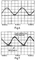
- Figures 6 and 7 show optical eye diagrams for a resolved optical signal from a conventional optical transmission system and from an optical transmission system according to the present invention, respectively. It is clear that although there is slight distortion of the resolved signal in Figure 7 compared to that in Figure 6, the signal to noise ratio is maintained meaning that all the information is still retrievable despite the fact that the bandwidth used to transmit it was substantially reduced.
- the distortion that is introduced into the resolved signal of Figure 7 arises due to dispersion introduced by the particular optical filters used in the transmission system. A filter that is specifically designed for this purpose would have improved dispersion characteristics.
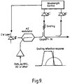
- Figures 8 and 9 show further examples of optical transmission systems according to the present invention.
- the output from the modulator 10 is coupled to an optical circulator 34 and the optical filter is arranged in the branch of the feedback loop connecting the first pin diode 16 to the control unit 14.
- the operation of the transmission system is similar to that described with reference to Figure 1 except the transmission profile of the grating is reversed so that the second half of the optical spectrum provided by the modulator 10 is transmitted as opposed to the first half.
- an optical coupler 36 is used in place of the circulator 34 and the optical filter is again provided in the feedback loop as shown.
- Figure 10 shows an example of an optical communications system according to the present invention.
- the communications system is a submarine communications system although the invention is not limited to this.
- the system has a submarine cable 38 connected between two endstations 40.
- Each of the endstations 40 includes an optical transmission system to transmit optical signals onto the cable 38.
- At least one of the optical transmission systems is an optical transmission system according to the present invention.
Abstract
Description
Claims (20)
- An optical transmission system for an optical communications system, comprises: an optical source;an optical modulator for modulating an optical output of the optical source;an optical filter arranged to substantially remove one of the upper and lower sidebands of the modulated optical output of the optical source; and,control means to control at least one of the optical source and the optical filter to ensure that substantially only half of the power of the modulated optical output of the optical source is transmitted, thereby reducing the bandwidth of the optical signals transmitted by the system.
- An optical transmission system according to claim 1, wherein a vestige of either the upper or lower sideband is also transmitted.
- An optical transmission system according to any preceding claim, in which the control means is arranged to move the wavelength spectrum of the modulated optical output of the optical source and a transmission profile of the optical filter relative to each other to control the power of the transmitted signal.
- An optical transmission system according to claim 3, in which the control means comprises a feedback loop arranged to detect reflected light from the optical filter and transmitted light from the optical filter and to move the wavelength spectrum of the modulated optical output of the optical source and the transmission profile of the optical filter relative to each other to ensure the detected power of the transmitted light and the detected power of the reflected light remain substantially equal.
- An optical transmission system according to any preceding claim, in which the optical source is a continuous wave laser source.
- An optical transmission system according to any preceding claim, in which the optical 5 modulator is a Mach Zehnder modulator.
- An optical transmission system according to any preceding claim, in which the optical filter comprises an optical fibre grating having a notch transmission profile, wherein a carrier frequency of the modulated optical output is controlled to substantially coincide with the rising edge of the notch transmission profile, thereby ensuring that substantially half of the modulated optical output of the optical source is transmitted and half is reflected.
- An optical transmission system according to claim 7, in which the control means is arranged to control the temperature of the optical fibre grating, thereby controlling the position of the rising edge of the transmission profile relative to the modulated optical output of the optical source.
- An optical transmission system according to claim 4, in which the feedback loop comprises a first branch having an optical sensor arranged to detect the intensity of the reflected light from the optical filter and a second branch having an optical sensor arranged to detect the intensity of the transmitted light from the optical filter.
- An optical transmission system according to claim 9, further comprising a control unit arranged to receive outputs from optical sensors in the first and second branches of the feedback loop, respectively, and vary the wavelength of the laser source and/or the position of the rising edge of the transmission profile of the optical filter accordingly.
- An optical transmission system according to claim 10, in which the control unit is arranged to control the temperature of the optical fibre grating, thereby controlling the position of the rising edge of the transmission profile relative to the modulated optical output of the optical source.
- An optical transmission system according to claim 10, further comprising an optical coupler arranged to couple the modulated optical output of the optical source from a transmission path in the transmission system to the optical filter positioned in the first branch of the feedback loop and couple reflected light from the optical filter back to the transmission path in the transmission system.
- An optical transmission system according to claim 12, further comprising a second optical coupler arranged to couple light from the first optical coupler to the optical sensor positioned in the second branch of the feedback loop.
- An optical transmission system for an optical communications system arranged to modulate an optical output from an optical source to provide an optical vestigial sideband signal for transmission.
- A line terminal endstation for a wavelength division multiplexed communications system, comprising a number of optical transmission systems for generating a number of individual channels, in which at least one of the optical transmission systems is an optical transmission system according to any preceding claim.
- An optical communications system comprising at least one line terminal endstation according to claim 15.
- An optical communications system according to claim 16, in which the communications system is a submarine communications system.
- An optical communications system according to claim 16, in which the communications system is a terrestrial communications system.
- An optical transmission system substantially as shown in and/or described with reference to any of Figures 1 to 10 of the accompanying drawings.
- An optical communications system substantially as shown in and/or described with reference to any of Figures 1 to 10 of the accompanying drawings.
Applications Claiming Priority (2)
| Application Number | Priority Date | Filing Date | Title |
|---|---|---|---|
| GBGB0000657.7A GB0000657D0 (en) | 2000-01-12 | 2000-01-12 | An optical transmission system |
| GB0000657 | 2000-01-12 |
Publications (3)
| Publication Number | Publication Date |
|---|---|
| EP1143643A2 true EP1143643A2 (en) | 2001-10-10 |
| EP1143643A3 EP1143643A3 (en) | 2004-11-24 |
| EP1143643B1 EP1143643B1 (en) | 2012-06-20 |
Family
ID=9883568
Family Applications (1)
| Application Number | Title | Priority Date | Filing Date |
|---|---|---|---|
| EP01300114A Expired - Lifetime EP1143643B1 (en) | 2000-01-12 | 2001-01-08 | An optical transmission system |
Country Status (4)
| Country | Link |
|---|---|
| US (1) | US6766116B2 (en) |
| EP (1) | EP1143643B1 (en) |
| JP (1) | JP2001264710A (en) |
| GB (1) | GB0000657D0 (en) |
Cited By (6)
| Publication number | Priority date | Publication date | Assignee | Title |
|---|---|---|---|---|
| GB2381399A (en) * | 2001-09-24 | 2003-04-30 | Ditech Comm Corp | Optical Vestigial Sideband (VSB) transmission |
| EP1345342A1 (en) * | 2002-03-04 | 2003-09-17 | Alcatel | An optical transmitter for transmitting signals with high data rates, an optical transmission system and a method therefor |
| US7302194B2 (en) | 2002-08-12 | 2007-11-27 | Alcatel | Optical filter and transmission system incorporating an optical filter |
| US7614545B2 (en) | 2003-03-24 | 2009-11-10 | Novo Nordisk A/S | Electronic marking of a medication cartridge |
| US8197449B2 (en) | 2005-05-10 | 2012-06-12 | Novo Nordisk A/S | Injection device comprising an optical sensor |
| US9950117B2 (en) | 2009-02-13 | 2018-04-24 | Novo Nordisk A/S | Medical device and cartridge |
Families Citing this family (30)
| Publication number | Priority date | Publication date | Assignee | Title |
|---|---|---|---|---|
| US7146103B2 (en) * | 1999-12-29 | 2006-12-05 | Forster Energy Llc | Optical communications using multiplexed single sideband transmission and heterodyne detection |
| US20060291868A1 (en) * | 1999-12-29 | 2006-12-28 | Forster Energy Llc | Optical communications using multiplexed single sideband transmission and heterodyne detection |
| US7209660B1 (en) | 1999-12-29 | 2007-04-24 | Forster Energy Llc | Optical communications using heterodyne detection |
| EP1309366B1 (en) | 2000-08-10 | 2007-02-21 | Novo Nordisk A/S | Medication delivery device comprising a support for a cartridge |
| US7039316B2 (en) * | 2001-01-30 | 2006-05-02 | The Regents Of The University Of California | Optical layer multicasting using a multiple sub-carrier header and a multicast switch with active header insertion via reflective single sideband optical processing |
| JP4646048B2 (en) * | 2001-03-02 | 2011-03-09 | 日本電気株式会社 | Single sideband signal light generation method and single sideband signal light generation circuit |
| US7848660B1 (en) * | 2001-06-20 | 2010-12-07 | Cisco Technology, Inc. | VSB transmitter using locked filter |
| EP1330061A1 (en) * | 2002-01-11 | 2003-07-23 | Alcatel | Optical filter and transmission system incorporating an optical filter |
| US7209669B2 (en) * | 2002-02-01 | 2007-04-24 | Lucent Technologies Inc. | Method and apparatus for synchronizing a pulse carver and a data modulator for optical telecommunication |
| JP2004104385A (en) * | 2002-09-09 | 2004-04-02 | Kddi Submarine Cable Systems Inc | Optical transmission system, optical transmission apparatus, and method for them |
| JP4547552B2 (en) * | 2005-08-31 | 2010-09-22 | 独立行政法人情報通信研究機構 | DSB-SC modulation system capable of erasing carriers and secondary components |
| CA2623118A1 (en) | 2005-09-22 | 2007-04-12 | Novo Nordisk A/S | Device and method for contact free absolute position determination |
| PL1999691T3 (en) | 2006-03-20 | 2011-02-28 | Novo Nordisk As | Contact free reading of cartridge identification codes |
| JP4892262B2 (en) * | 2006-03-23 | 2012-03-07 | 富士通株式会社 | Light source wavelength control device |
| EP2011223B1 (en) | 2006-04-12 | 2018-06-13 | Novo Nordisk A/S | Absolute position determination of movably mounted member in medication delivery device |
| CN101427107B (en) | 2006-04-26 | 2011-08-31 | 诺沃-诺迪斯克有限公司 | Contact free absolute position determination of a moving element in a medication delivery device |
| CN101641127B (en) | 2007-03-21 | 2012-11-28 | 诺沃-诺迪斯克有限公司 | A medical delivery system having container recognition and container for use with the medical delivery system |
| CA2683885C (en) * | 2007-04-24 | 2016-04-19 | Telcordia Technologies, Inc. | Systems and methods for photonically assisted rf filtering |
| US20090028555A1 (en) * | 2007-07-27 | 2009-01-29 | Azea Networks Limited | Optical filter |
| JP5182058B2 (en) * | 2008-12-16 | 2013-04-10 | 富士通株式会社 | WDM optical transmission method and WDM optical transmission system |
| US8135288B2 (en) * | 2009-02-03 | 2012-03-13 | The Boeing Company | System and method for a photonic system |
| US8768121B2 (en) * | 2009-03-10 | 2014-07-01 | Her Majesty The Queen In Right Of Canada, As Represented By The Minister Of Industry, Through The Communications Research Centre Canada | Photonic filtering of electrical signals |
| US20140226974A1 (en) * | 2013-02-14 | 2014-08-14 | Chen-Kuo Sun | System and Method for Filtering an Optical Signal to Avoid Fading and to Optimize Linearity |
| CN105210247A (en) * | 2013-06-18 | 2015-12-30 | 华为技术有限公司 | Optical component, laser, optical network system and monitoring method |
| US9755754B2 (en) | 2015-02-24 | 2017-09-05 | Lockheed Martin Corporation | Electro-absorption modulator adaptive equalizer systems and methods |
| US9705280B2 (en) | 2015-02-24 | 2017-07-11 | Lockheed Martin Corporation | Systems and methods for adaptively controlling a thermoelectric cooler |
| US9698911B2 (en) | 2015-06-30 | 2017-07-04 | Lockheed Martin Corporation | Systems, devices, and methods for photonic to radio frequency downconversion |
| US9658477B2 (en) | 2015-06-30 | 2017-05-23 | Lockheed Martin Corporation | Systems, devices, and methods for photonic to radio frequency upconversion |
| JP6613761B2 (en) | 2015-09-24 | 2019-12-04 | 富士通株式会社 | Optical transmission system, control device and control method for wavelength tunable optical filter |
| US11132552B1 (en) * | 2021-02-12 | 2021-09-28 | ShipIn Systems Inc. | System and method for bandwidth reduction and communication of visual events |
Citations (1)
| Publication number | Priority date | Publication date | Assignee | Title |
|---|---|---|---|---|
| WO1996037042A1 (en) * | 1995-05-19 | 1996-11-21 | Telefonaktiebolaget Lm Ericsson (Publ) | Method and apparatus for transmitting signals in an optical fibre |
Family Cites Families (6)
| Publication number | Priority date | Publication date | Assignee | Title |
|---|---|---|---|---|
| EP0466182B1 (en) | 1990-07-13 | 2002-10-16 | Nec Corporation | Optical communication apparatus using intensity modulation |
| JPH08288573A (en) * | 1995-04-17 | 1996-11-01 | Sumitomo Electric Ind Ltd | Optical fiber amplifier |
| CA2188358A1 (en) * | 1996-10-21 | 1998-04-21 | Michael J. Sieben | optical modulation system |
| US6459519B1 (en) | 1997-04-09 | 2002-10-01 | Matsushita Electric Industrial Co., Ltd. | Optical transmitter-receiver |
| JPH11205240A (en) * | 1998-01-08 | 1999-07-30 | Toshiba Corp | Optical transmitter |
| US20030058509A1 (en) * | 2001-09-24 | 2003-03-27 | Ditech Communications Corporation | Optical vestigial sideband (VSB) transmission |
-
2000
- 2000-01-12 GB GBGB0000657.7A patent/GB0000657D0/en not_active Ceased
-
2001
- 2001-01-08 EP EP01300114A patent/EP1143643B1/en not_active Expired - Lifetime
- 2001-01-10 JP JP2001002557A patent/JP2001264710A/en active Pending
- 2001-01-11 US US09/757,567 patent/US6766116B2/en not_active Expired - Lifetime
Patent Citations (1)
| Publication number | Priority date | Publication date | Assignee | Title |
|---|---|---|---|---|
| WO1996037042A1 (en) * | 1995-05-19 | 1996-11-21 | Telefonaktiebolaget Lm Ericsson (Publ) | Method and apparatus for transmitting signals in an optical fibre |
Cited By (8)
| Publication number | Priority date | Publication date | Assignee | Title |
|---|---|---|---|---|
| GB2381399A (en) * | 2001-09-24 | 2003-04-30 | Ditech Comm Corp | Optical Vestigial Sideband (VSB) transmission |
| EP1345342A1 (en) * | 2002-03-04 | 2003-09-17 | Alcatel | An optical transmitter for transmitting signals with high data rates, an optical transmission system and a method therefor |
| US7302194B2 (en) | 2002-08-12 | 2007-11-27 | Alcatel | Optical filter and transmission system incorporating an optical filter |
| US7614545B2 (en) | 2003-03-24 | 2009-11-10 | Novo Nordisk A/S | Electronic marking of a medication cartridge |
| US8197449B2 (en) | 2005-05-10 | 2012-06-12 | Novo Nordisk A/S | Injection device comprising an optical sensor |
| US8771238B2 (en) | 2005-05-10 | 2014-07-08 | Novo Nordisk A/S | Injection device comprising an optical sensor |
| US9522238B2 (en) | 2005-05-10 | 2016-12-20 | Novo Nordisk A/S | Injection device comprising an optical sensor |
| US9950117B2 (en) | 2009-02-13 | 2018-04-24 | Novo Nordisk A/S | Medical device and cartridge |
Also Published As
| Publication number | Publication date |
|---|---|
| US20020075546A1 (en) | 2002-06-20 |
| EP1143643B1 (en) | 2012-06-20 |
| GB0000657D0 (en) | 2000-03-01 |
| JP2001264710A (en) | 2001-09-26 |
| US6766116B2 (en) | 2004-07-20 |
| EP1143643A3 (en) | 2004-11-24 |
Similar Documents
| Publication | Publication Date | Title |
|---|---|---|
| EP1143643B1 (en) | An optical transmission system | |
| JP3910003B2 (en) | Optical receiving station, optical communication system, and dispersion control method | |
| US6198757B1 (en) | Control system for wavelength stabilization of a laser source | |
| CA2032089C (en) | Optimized wavelength-division-multiplexed lightwave communication system | |
| US7620326B2 (en) | Method for transmitting at least one first and second data signal in polarization multiplex in an optical transmission system | |
| CN100578973C (en) | Wavelength division multiplexing optical transmission system and wavelength division multiplexing optical transmission method | |
| US6788899B2 (en) | Dynamic wavelength add/drop multiplexer for UDWDM optical communication system | |
| AU629749B2 (en) | Single wavelength bidirectional optical fiber communication link | |
| US20030048509A1 (en) | Optical communications terminal station, optical signal transmission method, and optical signal increasing method in wavelength multiplexing system | |
| EP1617576B1 (en) | Bandwidth limited frequency shift keying modulation format | |
| US20100263001A1 (en) | Optical-to-millimeter wave conversion | |
| CN1497893A (en) | Double-binary optical transmission device | |
| EP1424795B1 (en) | Optical transmission system using optical phase modulator | |
| JP3527607B2 (en) | Optical control signal transmission device | |
| EP1578041B1 (en) | Optical duo-binary transmission apparatus using polarization modulator | |
| EP0622913B1 (en) | Optical transmission apparatus with a directly modulated emitter and an optical filtering before the receiver | |
| US7536111B1 (en) | Optical communication with phase encoding and optical filtering | |
| US20050041983A1 (en) | Method of forming a coded optical signal with a return to zero or non return to zero format | |
| EP1618691B1 (en) | Data format for high bit rate wdm transmission | |
| US10355784B2 (en) | Method and optical transmitter device for creating an optical binary digital transmit signal | |
| US7848660B1 (en) | VSB transmitter using locked filter | |
| EP1365528B1 (en) | Optical transmission system incorporating optical filters | |
| EP0458251A2 (en) | Single wavelength bidirectional optical fiber communication link | |
| JPH1022914A (en) | Optical communication method | |
| JPH1065616A (en) | Optical signal multiplex transmitting device |
Legal Events
| Date | Code | Title | Description |
|---|---|---|---|
| PUAI | Public reference made under article 153(3) epc to a published international application that has entered the european phase |
Free format text: ORIGINAL CODE: 0009012 |
|
| AK | Designated contracting states |
Kind code of ref document: A2 Designated state(s): AT BE CH CY DE DK ES FI FR GB GR IE IT LI LU MC NL PT SE TR |
|
| AX | Request for extension of the european patent |
Free format text: AL;LT;LV;MK;RO;SI |
|
| PUAL | Search report despatched |
Free format text: ORIGINAL CODE: 0009013 |
|
| AK | Designated contracting states |
Kind code of ref document: A3 Designated state(s): AT BE CH CY DE DK ES FI FR GB GR IE IT LI LU MC NL PT SE TR |
|
| AX | Request for extension of the european patent |
Extension state: AL LT LV MK RO SI |
|
| 17P | Request for examination filed |
Effective date: 20041216 |
|
| AKX | Designation fees paid |
Designated state(s): AT BE CH CY DE DK ES FI FR GB GR IE IT LI LU MC NL PT SE TR |
|
| RAP1 | Party data changed (applicant data changed or rights of an application transferred) |
Owner name: ALCATEL LUCENT |
|
| 17Q | First examination report despatched |
Effective date: 20080222 |
|
| GRAP | Despatch of communication of intention to grant a patent |
Free format text: ORIGINAL CODE: EPIDOSNIGR1 |
|
| RAP1 | Party data changed (applicant data changed or rights of an application transferred) |
Owner name: ALCATEL LUCENT |
|
| GRAS | Grant fee paid |
Free format text: ORIGINAL CODE: EPIDOSNIGR3 |
|
| GRAA | (expected) grant |
Free format text: ORIGINAL CODE: 0009210 |
|
| AK | Designated contracting states |
Kind code of ref document: B1 Designated state(s): AT BE CH CY DE DK ES FI FR GB GR IE IT LI LU MC NL PT SE TR |
|
| REG | Reference to a national code |
Ref country code: GB Ref legal event code: FG4D |
|
| REG | Reference to a national code |
Ref country code: CH Ref legal event code: EP |
|
| REG | Reference to a national code |
Ref country code: AT Ref legal event code: REF Ref document number: 563544 Country of ref document: AT Kind code of ref document: T Effective date: 20120715 |
|
| REG | Reference to a national code |
Ref country code: IE Ref legal event code: FG4D |
|
| REG | Reference to a national code |
Ref country code: DE Ref legal event code: R096 Ref document number: 60146733 Country of ref document: DE Effective date: 20120809 |
|
| PG25 | Lapsed in a contracting state [announced via postgrant information from national office to epo] |
Ref country code: SE Free format text: LAPSE BECAUSE OF FAILURE TO SUBMIT A TRANSLATION OF THE DESCRIPTION OR TO PAY THE FEE WITHIN THE PRESCRIBED TIME-LIMIT Effective date: 20120620 Ref country code: FI Free format text: LAPSE BECAUSE OF FAILURE TO SUBMIT A TRANSLATION OF THE DESCRIPTION OR TO PAY THE FEE WITHIN THE PRESCRIBED TIME-LIMIT Effective date: 20120620 |
|
| REG | Reference to a national code |
Ref country code: NL Ref legal event code: VDEP Effective date: 20120620 |
|
| REG | Reference to a national code |
Ref country code: AT Ref legal event code: MK05 Ref document number: 563544 Country of ref document: AT Kind code of ref document: T Effective date: 20120620 |
|
| PG25 | Lapsed in a contracting state [announced via postgrant information from national office to epo] |
Ref country code: GR Free format text: LAPSE BECAUSE OF FAILURE TO SUBMIT A TRANSLATION OF THE DESCRIPTION OR TO PAY THE FEE WITHIN THE PRESCRIBED TIME-LIMIT Effective date: 20120921 |
|
| PG25 | Lapsed in a contracting state [announced via postgrant information from national office to epo] |
Ref country code: CY Free format text: LAPSE BECAUSE OF FAILURE TO SUBMIT A TRANSLATION OF THE DESCRIPTION OR TO PAY THE FEE WITHIN THE PRESCRIBED TIME-LIMIT Effective date: 20120620 Ref country code: AT Free format text: LAPSE BECAUSE OF FAILURE TO SUBMIT A TRANSLATION OF THE DESCRIPTION OR TO PAY THE FEE WITHIN THE PRESCRIBED TIME-LIMIT Effective date: 20120620 Ref country code: BE Free format text: LAPSE BECAUSE OF FAILURE TO SUBMIT A TRANSLATION OF THE DESCRIPTION OR TO PAY THE FEE WITHIN THE PRESCRIBED TIME-LIMIT Effective date: 20120620 |
|
| PG25 | Lapsed in a contracting state [announced via postgrant information from national office to epo] |
Ref country code: PT Free format text: LAPSE BECAUSE OF FAILURE TO SUBMIT A TRANSLATION OF THE DESCRIPTION OR TO PAY THE FEE WITHIN THE PRESCRIBED TIME-LIMIT Effective date: 20121022 Ref country code: IT Free format text: LAPSE BECAUSE OF FAILURE TO SUBMIT A TRANSLATION OF THE DESCRIPTION OR TO PAY THE FEE WITHIN THE PRESCRIBED TIME-LIMIT Effective date: 20120620 |
|
| PG25 | Lapsed in a contracting state [announced via postgrant information from national office to epo] |
Ref country code: NL Free format text: LAPSE BECAUSE OF FAILURE TO SUBMIT A TRANSLATION OF THE DESCRIPTION OR TO PAY THE FEE WITHIN THE PRESCRIBED TIME-LIMIT Effective date: 20120620 |
|
| PLBE | No opposition filed within time limit |
Free format text: ORIGINAL CODE: 0009261 |
|
| STAA | Information on the status of an ep patent application or granted ep patent |
Free format text: STATUS: NO OPPOSITION FILED WITHIN TIME LIMIT |
|
| PG25 | Lapsed in a contracting state [announced via postgrant information from national office to epo] |
Ref country code: ES Free format text: LAPSE BECAUSE OF FAILURE TO SUBMIT A TRANSLATION OF THE DESCRIPTION OR TO PAY THE FEE WITHIN THE PRESCRIBED TIME-LIMIT Effective date: 20121001 Ref country code: DK Free format text: LAPSE BECAUSE OF FAILURE TO SUBMIT A TRANSLATION OF THE DESCRIPTION OR TO PAY THE FEE WITHIN THE PRESCRIBED TIME-LIMIT Effective date: 20120620 |
|
| 26N | No opposition filed |
Effective date: 20130321 |
|
| REG | Reference to a national code |
Ref country code: DE Ref legal event code: R097 Ref document number: 60146733 Country of ref document: DE Effective date: 20130321 |
|
| PG25 | Lapsed in a contracting state [announced via postgrant information from national office to epo] |
Ref country code: MC Free format text: LAPSE BECAUSE OF NON-PAYMENT OF DUE FEES Effective date: 20130131 |
|
| REG | Reference to a national code |
Ref country code: CH Ref legal event code: PL |
|
| REG | Reference to a national code |
Ref country code: GB Ref legal event code: 732E Free format text: REGISTERED BETWEEN 20130926 AND 20131002 Ref country code: IE Ref legal event code: MM4A |
|
| PG25 | Lapsed in a contracting state [announced via postgrant information from national office to epo] |
Ref country code: LI Free format text: LAPSE BECAUSE OF NON-PAYMENT OF DUE FEES Effective date: 20130131 Ref country code: CH Free format text: LAPSE BECAUSE OF NON-PAYMENT OF DUE FEES Effective date: 20130131 |
|
| REG | Reference to a national code |
Ref country code: FR Ref legal event code: GC Effective date: 20131018 |
|
| PG25 | Lapsed in a contracting state [announced via postgrant information from national office to epo] |
Ref country code: IE Free format text: LAPSE BECAUSE OF NON-PAYMENT OF DUE FEES Effective date: 20130108 |
|
| REG | Reference to a national code |
Ref country code: FR Ref legal event code: RG Effective date: 20141016 |
|
| REG | Reference to a national code |
Ref country code: FR Ref legal event code: PLFP Year of fee payment: 15 |
|
| PG25 | Lapsed in a contracting state [announced via postgrant information from national office to epo] |
Ref country code: TR Free format text: LAPSE BECAUSE OF FAILURE TO SUBMIT A TRANSLATION OF THE DESCRIPTION OR TO PAY THE FEE WITHIN THE PRESCRIBED TIME-LIMIT Effective date: 20120620 |
|
| PG25 | Lapsed in a contracting state [announced via postgrant information from national office to epo] |
Ref country code: LU Free format text: LAPSE BECAUSE OF NON-PAYMENT OF DUE FEES Effective date: 20130108 |
|
| REG | Reference to a national code |
Ref country code: FR Ref legal event code: PLFP Year of fee payment: 16 |
|
| REG | Reference to a national code |
Ref country code: FR Ref legal event code: PLFP Year of fee payment: 17 |
|
| PGFP | Annual fee paid to national office [announced via postgrant information from national office to epo] |
Ref country code: DE Payment date: 20170120 Year of fee payment: 17 Ref country code: FR Payment date: 20170120 Year of fee payment: 17 |
|
| PGFP | Annual fee paid to national office [announced via postgrant information from national office to epo] |
Ref country code: GB Payment date: 20170119 Year of fee payment: 17 |
|
| REG | Reference to a national code |
Ref country code: DE Ref legal event code: R119 Ref document number: 60146733 Country of ref document: DE |
|
| GBPC | Gb: european patent ceased through non-payment of renewal fee |
Effective date: 20180108 |
|
| PG25 | Lapsed in a contracting state [announced via postgrant information from national office to epo] |
Ref country code: FR Free format text: LAPSE BECAUSE OF NON-PAYMENT OF DUE FEES Effective date: 20180131 Ref country code: DE Free format text: LAPSE BECAUSE OF NON-PAYMENT OF DUE FEES Effective date: 20180801 |
|
| REG | Reference to a national code |
Ref country code: FR Ref legal event code: ST Effective date: 20180928 |
|
| PG25 | Lapsed in a contracting state [announced via postgrant information from national office to epo] |
Ref country code: GB Free format text: LAPSE BECAUSE OF NON-PAYMENT OF DUE FEES Effective date: 20180108 |
|
| REG | Reference to a national code |
Ref country code: DE Ref legal event code: R073 Ref document number: 60146733 Country of ref document: DE |
|
| REG | Reference to a national code |
Ref country code: DE Ref legal event code: R082 Ref document number: 60146733 Country of ref document: DE Ref country code: DE Ref legal event code: R081 Ref document number: 60146733 Country of ref document: DE Owner name: PROVENANCE ASSET GROUP LLC, PITTSFORD, US Free format text: FORMER OWNER: ALCATEL LUCENT, PARIS, FR |
|
| REG | Reference to a national code |
Ref country code: DE Ref legal event code: R124 Ref document number: 60146733 Country of ref document: DE |