EP1143885B1 - Truncated open intervertebral spacers - Google Patents
Truncated open intervertebral spacers Download PDFInfo
- Publication number
- EP1143885B1 EP1143885B1 EP00903218A EP00903218A EP1143885B1 EP 1143885 B1 EP1143885 B1 EP 1143885B1 EP 00903218 A EP00903218 A EP 00903218A EP 00903218 A EP00903218 A EP 00903218A EP 1143885 B1 EP1143885 B1 EP 1143885B1
- Authority
- EP
- European Patent Office
- Prior art keywords
- spacer
- bone
- interbody fusion
- elongated body
- chamber
- Prior art date
- Legal status (The legal status is an assumption and is not a legal conclusion. Google has not performed a legal analysis and makes no representation as to the accuracy of the status listed.)
- Expired - Lifetime
Links
Images


Classifications
-
- A—HUMAN NECESSITIES
- A61—MEDICAL OR VETERINARY SCIENCE; HYGIENE
- A61F—FILTERS IMPLANTABLE INTO BLOOD VESSELS; PROSTHESES; DEVICES PROVIDING PATENCY TO, OR PREVENTING COLLAPSING OF, TUBULAR STRUCTURES OF THE BODY, e.g. STENTS; ORTHOPAEDIC, NURSING OR CONTRACEPTIVE DEVICES; FOMENTATION; TREATMENT OR PROTECTION OF EYES OR EARS; BANDAGES, DRESSINGS OR ABSORBENT PADS; FIRST-AID KITS
- A61F2/00—Filters implantable into blood vessels; Prostheses, i.e. artificial substitutes or replacements for parts of the body; Appliances for connecting them with the body; Devices providing patency to, or preventing collapsing of, tubular structures of the body, e.g. stents
- A61F2/02—Prostheses implantable into the body
- A61F2/30—Joints
- A61F2/46—Special tools or methods for implanting or extracting artificial joints, accessories, bone grafts or substitutes, or particular adaptations therefor
- A61F2/4603—Special tools or methods for implanting or extracting artificial joints, accessories, bone grafts or substitutes, or particular adaptations therefor for insertion or extraction of endoprosthetic joints or of accessories thereof
- A61F2/4611—Special tools or methods for implanting or extracting artificial joints, accessories, bone grafts or substitutes, or particular adaptations therefor for insertion or extraction of endoprosthetic joints or of accessories thereof of spinal prostheses
-
- A—HUMAN NECESSITIES
- A61—MEDICAL OR VETERINARY SCIENCE; HYGIENE
- A61F—FILTERS IMPLANTABLE INTO BLOOD VESSELS; PROSTHESES; DEVICES PROVIDING PATENCY TO, OR PREVENTING COLLAPSING OF, TUBULAR STRUCTURES OF THE BODY, e.g. STENTS; ORTHOPAEDIC, NURSING OR CONTRACEPTIVE DEVICES; FOMENTATION; TREATMENT OR PROTECTION OF EYES OR EARS; BANDAGES, DRESSINGS OR ABSORBENT PADS; FIRST-AID KITS
- A61F2/00—Filters implantable into blood vessels; Prostheses, i.e. artificial substitutes or replacements for parts of the body; Appliances for connecting them with the body; Devices providing patency to, or preventing collapsing of, tubular structures of the body, e.g. stents
- A61F2/02—Prostheses implantable into the body
- A61F2/28—Bones
-
- A—HUMAN NECESSITIES
- A61—MEDICAL OR VETERINARY SCIENCE; HYGIENE
- A61F—FILTERS IMPLANTABLE INTO BLOOD VESSELS; PROSTHESES; DEVICES PROVIDING PATENCY TO, OR PREVENTING COLLAPSING OF, TUBULAR STRUCTURES OF THE BODY, e.g. STENTS; ORTHOPAEDIC, NURSING OR CONTRACEPTIVE DEVICES; FOMENTATION; TREATMENT OR PROTECTION OF EYES OR EARS; BANDAGES, DRESSINGS OR ABSORBENT PADS; FIRST-AID KITS
- A61F2/00—Filters implantable into blood vessels; Prostheses, i.e. artificial substitutes or replacements for parts of the body; Appliances for connecting them with the body; Devices providing patency to, or preventing collapsing of, tubular structures of the body, e.g. stents
- A61F2/02—Prostheses implantable into the body
- A61F2/30—Joints
- A61F2/44—Joints for the spine, e.g. vertebrae, spinal discs
- A61F2/4455—Joints for the spine, e.g. vertebrae, spinal discs for the fusion of spinal bodies, e.g. intervertebral fusion of adjacent spinal bodies, e.g. fusion cages
- A61F2/446—Joints for the spine, e.g. vertebrae, spinal discs for the fusion of spinal bodies, e.g. intervertebral fusion of adjacent spinal bodies, e.g. fusion cages having a circular or elliptical cross-section substantially parallel to the axis of the spine, e.g. cylinders or frustocones
-
- A—HUMAN NECESSITIES
- A61—MEDICAL OR VETERINARY SCIENCE; HYGIENE
- A61F—FILTERS IMPLANTABLE INTO BLOOD VESSELS; PROSTHESES; DEVICES PROVIDING PATENCY TO, OR PREVENTING COLLAPSING OF, TUBULAR STRUCTURES OF THE BODY, e.g. STENTS; ORTHOPAEDIC, NURSING OR CONTRACEPTIVE DEVICES; FOMENTATION; TREATMENT OR PROTECTION OF EYES OR EARS; BANDAGES, DRESSINGS OR ABSORBENT PADS; FIRST-AID KITS
- A61F2/00—Filters implantable into blood vessels; Prostheses, i.e. artificial substitutes or replacements for parts of the body; Appliances for connecting them with the body; Devices providing patency to, or preventing collapsing of, tubular structures of the body, e.g. stents
- A61F2/02—Prostheses implantable into the body
- A61F2/30—Joints
- A61F2/44—Joints for the spine, e.g. vertebrae, spinal discs
- A61F2/442—Intervertebral or spinal discs, e.g. resilient
-
- A—HUMAN NECESSITIES
- A61—MEDICAL OR VETERINARY SCIENCE; HYGIENE
- A61F—FILTERS IMPLANTABLE INTO BLOOD VESSELS; PROSTHESES; DEVICES PROVIDING PATENCY TO, OR PREVENTING COLLAPSING OF, TUBULAR STRUCTURES OF THE BODY, e.g. STENTS; ORTHOPAEDIC, NURSING OR CONTRACEPTIVE DEVICES; FOMENTATION; TREATMENT OR PROTECTION OF EYES OR EARS; BANDAGES, DRESSINGS OR ABSORBENT PADS; FIRST-AID KITS
- A61F2/00—Filters implantable into blood vessels; Prostheses, i.e. artificial substitutes or replacements for parts of the body; Appliances for connecting them with the body; Devices providing patency to, or preventing collapsing of, tubular structures of the body, e.g. stents
- A61F2/02—Prostheses implantable into the body
- A61F2/28—Bones
- A61F2002/2817—Bone stimulation by chemical reactions or by osteogenic or biological products for enhancing ossification, e.g. by bone morphogenetic or morphogenic proteins [BMP] or by transforming growth factors [TGF]
-
- A—HUMAN NECESSITIES
- A61—MEDICAL OR VETERINARY SCIENCE; HYGIENE
- A61F—FILTERS IMPLANTABLE INTO BLOOD VESSELS; PROSTHESES; DEVICES PROVIDING PATENCY TO, OR PREVENTING COLLAPSING OF, TUBULAR STRUCTURES OF THE BODY, e.g. STENTS; ORTHOPAEDIC, NURSING OR CONTRACEPTIVE DEVICES; FOMENTATION; TREATMENT OR PROTECTION OF EYES OR EARS; BANDAGES, DRESSINGS OR ABSORBENT PADS; FIRST-AID KITS
- A61F2/00—Filters implantable into blood vessels; Prostheses, i.e. artificial substitutes or replacements for parts of the body; Appliances for connecting them with the body; Devices providing patency to, or preventing collapsing of, tubular structures of the body, e.g. stents
- A61F2/02—Prostheses implantable into the body
- A61F2/28—Bones
- A61F2002/2835—Bone graft implants for filling a bony defect or an endoprosthesis cavity, e.g. by synthetic material or biological material
- A61F2002/2839—Bone plugs or bone graft dowels
-
- A—HUMAN NECESSITIES
- A61—MEDICAL OR VETERINARY SCIENCE; HYGIENE
- A61F—FILTERS IMPLANTABLE INTO BLOOD VESSELS; PROSTHESES; DEVICES PROVIDING PATENCY TO, OR PREVENTING COLLAPSING OF, TUBULAR STRUCTURES OF THE BODY, e.g. STENTS; ORTHOPAEDIC, NURSING OR CONTRACEPTIVE DEVICES; FOMENTATION; TREATMENT OR PROTECTION OF EYES OR EARS; BANDAGES, DRESSINGS OR ABSORBENT PADS; FIRST-AID KITS
- A61F2/00—Filters implantable into blood vessels; Prostheses, i.e. artificial substitutes or replacements for parts of the body; Appliances for connecting them with the body; Devices providing patency to, or preventing collapsing of, tubular structures of the body, e.g. stents
- A61F2/02—Prostheses implantable into the body
- A61F2/30—Joints
- A61F2002/30001—Additional features of subject-matter classified in A61F2/28, A61F2/30 and subgroups thereof
- A61F2002/30108—Shapes
- A61F2002/3011—Cross-sections or two-dimensional shapes
- A61F2002/30112—Rounded shapes, e.g. with rounded corners
- A61F2002/30131—Rounded shapes, e.g. with rounded corners horseshoe- or crescent- or C-shaped or U-shaped
-
- A—HUMAN NECESSITIES
- A61—MEDICAL OR VETERINARY SCIENCE; HYGIENE
- A61F—FILTERS IMPLANTABLE INTO BLOOD VESSELS; PROSTHESES; DEVICES PROVIDING PATENCY TO, OR PREVENTING COLLAPSING OF, TUBULAR STRUCTURES OF THE BODY, e.g. STENTS; ORTHOPAEDIC, NURSING OR CONTRACEPTIVE DEVICES; FOMENTATION; TREATMENT OR PROTECTION OF EYES OR EARS; BANDAGES, DRESSINGS OR ABSORBENT PADS; FIRST-AID KITS
- A61F2/00—Filters implantable into blood vessels; Prostheses, i.e. artificial substitutes or replacements for parts of the body; Appliances for connecting them with the body; Devices providing patency to, or preventing collapsing of, tubular structures of the body, e.g. stents
- A61F2/02—Prostheses implantable into the body
- A61F2/30—Joints
- A61F2002/30001—Additional features of subject-matter classified in A61F2/28, A61F2/30 and subgroups thereof
- A61F2002/30316—The prosthesis having different structural features at different locations within the same prosthesis; Connections between prosthetic parts; Special structural features of bone or joint prostheses not otherwise provided for
- A61F2002/30535—Special structural features of bone or joint prostheses not otherwise provided for
- A61F2002/30593—Special structural features of bone or joint prostheses not otherwise provided for hollow
-
- A—HUMAN NECESSITIES
- A61—MEDICAL OR VETERINARY SCIENCE; HYGIENE
- A61F—FILTERS IMPLANTABLE INTO BLOOD VESSELS; PROSTHESES; DEVICES PROVIDING PATENCY TO, OR PREVENTING COLLAPSING OF, TUBULAR STRUCTURES OF THE BODY, e.g. STENTS; ORTHOPAEDIC, NURSING OR CONTRACEPTIVE DEVICES; FOMENTATION; TREATMENT OR PROTECTION OF EYES OR EARS; BANDAGES, DRESSINGS OR ABSORBENT PADS; FIRST-AID KITS
- A61F2/00—Filters implantable into blood vessels; Prostheses, i.e. artificial substitutes or replacements for parts of the body; Appliances for connecting them with the body; Devices providing patency to, or preventing collapsing of, tubular structures of the body, e.g. stents
- A61F2/02—Prostheses implantable into the body
- A61F2/30—Joints
- A61F2002/30001—Additional features of subject-matter classified in A61F2/28, A61F2/30 and subgroups thereof
- A61F2002/30316—The prosthesis having different structural features at different locations within the same prosthesis; Connections between prosthetic parts; Special structural features of bone or joint prostheses not otherwise provided for
- A61F2002/30535—Special structural features of bone or joint prostheses not otherwise provided for
- A61F2002/30604—Special structural features of bone or joint prostheses not otherwise provided for modular
-
- A—HUMAN NECESSITIES
- A61—MEDICAL OR VETERINARY SCIENCE; HYGIENE
- A61F—FILTERS IMPLANTABLE INTO BLOOD VESSELS; PROSTHESES; DEVICES PROVIDING PATENCY TO, OR PREVENTING COLLAPSING OF, TUBULAR STRUCTURES OF THE BODY, e.g. STENTS; ORTHOPAEDIC, NURSING OR CONTRACEPTIVE DEVICES; FOMENTATION; TREATMENT OR PROTECTION OF EYES OR EARS; BANDAGES, DRESSINGS OR ABSORBENT PADS; FIRST-AID KITS
- A61F2/00—Filters implantable into blood vessels; Prostheses, i.e. artificial substitutes or replacements for parts of the body; Appliances for connecting them with the body; Devices providing patency to, or preventing collapsing of, tubular structures of the body, e.g. stents
- A61F2/02—Prostheses implantable into the body
- A61F2/30—Joints
- A61F2002/30001—Additional features of subject-matter classified in A61F2/28, A61F2/30 and subgroups thereof
- A61F2002/30667—Features concerning an interaction with the environment or a particular use of the prosthesis
- A61F2002/30677—Means for introducing or releasing pharmaceutical products, e.g. antibiotics, into the body
-
- A—HUMAN NECESSITIES
- A61—MEDICAL OR VETERINARY SCIENCE; HYGIENE
- A61F—FILTERS IMPLANTABLE INTO BLOOD VESSELS; PROSTHESES; DEVICES PROVIDING PATENCY TO, OR PREVENTING COLLAPSING OF, TUBULAR STRUCTURES OF THE BODY, e.g. STENTS; ORTHOPAEDIC, NURSING OR CONTRACEPTIVE DEVICES; FOMENTATION; TREATMENT OR PROTECTION OF EYES OR EARS; BANDAGES, DRESSINGS OR ABSORBENT PADS; FIRST-AID KITS
- A61F2/00—Filters implantable into blood vessels; Prostheses, i.e. artificial substitutes or replacements for parts of the body; Appliances for connecting them with the body; Devices providing patency to, or preventing collapsing of, tubular structures of the body, e.g. stents
- A61F2/02—Prostheses implantable into the body
- A61F2/30—Joints
- A61F2/30767—Special external or bone-contacting surface, e.g. coating for improving bone ingrowth
- A61F2/30771—Special external or bone-contacting surface, e.g. coating for improving bone ingrowth applied in original prostheses, e.g. holes or grooves
- A61F2002/30772—Apertures or holes, e.g. of circular cross section
- A61F2002/30777—Oblong apertures
-
- A—HUMAN NECESSITIES
- A61—MEDICAL OR VETERINARY SCIENCE; HYGIENE
- A61F—FILTERS IMPLANTABLE INTO BLOOD VESSELS; PROSTHESES; DEVICES PROVIDING PATENCY TO, OR PREVENTING COLLAPSING OF, TUBULAR STRUCTURES OF THE BODY, e.g. STENTS; ORTHOPAEDIC, NURSING OR CONTRACEPTIVE DEVICES; FOMENTATION; TREATMENT OR PROTECTION OF EYES OR EARS; BANDAGES, DRESSINGS OR ABSORBENT PADS; FIRST-AID KITS
- A61F2/00—Filters implantable into blood vessels; Prostheses, i.e. artificial substitutes or replacements for parts of the body; Appliances for connecting them with the body; Devices providing patency to, or preventing collapsing of, tubular structures of the body, e.g. stents
- A61F2/02—Prostheses implantable into the body
- A61F2/30—Joints
- A61F2/30767—Special external or bone-contacting surface, e.g. coating for improving bone ingrowth
- A61F2/30771—Special external or bone-contacting surface, e.g. coating for improving bone ingrowth applied in original prostheses, e.g. holes or grooves
- A61F2002/30772—Apertures or holes, e.g. of circular cross section
- A61F2002/30784—Plurality of holes
- A61F2002/30787—Plurality of holes inclined obliquely with respect to each other
-
- A—HUMAN NECESSITIES
- A61—MEDICAL OR VETERINARY SCIENCE; HYGIENE
- A61F—FILTERS IMPLANTABLE INTO BLOOD VESSELS; PROSTHESES; DEVICES PROVIDING PATENCY TO, OR PREVENTING COLLAPSING OF, TUBULAR STRUCTURES OF THE BODY, e.g. STENTS; ORTHOPAEDIC, NURSING OR CONTRACEPTIVE DEVICES; FOMENTATION; TREATMENT OR PROTECTION OF EYES OR EARS; BANDAGES, DRESSINGS OR ABSORBENT PADS; FIRST-AID KITS
- A61F2/00—Filters implantable into blood vessels; Prostheses, i.e. artificial substitutes or replacements for parts of the body; Appliances for connecting them with the body; Devices providing patency to, or preventing collapsing of, tubular structures of the body, e.g. stents
- A61F2/02—Prostheses implantable into the body
- A61F2/30—Joints
- A61F2/30767—Special external or bone-contacting surface, e.g. coating for improving bone ingrowth
- A61F2/30771—Special external or bone-contacting surface, e.g. coating for improving bone ingrowth applied in original prostheses, e.g. holes or grooves
- A61F2002/3082—Grooves
-
- A—HUMAN NECESSITIES
- A61—MEDICAL OR VETERINARY SCIENCE; HYGIENE
- A61F—FILTERS IMPLANTABLE INTO BLOOD VESSELS; PROSTHESES; DEVICES PROVIDING PATENCY TO, OR PREVENTING COLLAPSING OF, TUBULAR STRUCTURES OF THE BODY, e.g. STENTS; ORTHOPAEDIC, NURSING OR CONTRACEPTIVE DEVICES; FOMENTATION; TREATMENT OR PROTECTION OF EYES OR EARS; BANDAGES, DRESSINGS OR ABSORBENT PADS; FIRST-AID KITS
- A61F2/00—Filters implantable into blood vessels; Prostheses, i.e. artificial substitutes or replacements for parts of the body; Appliances for connecting them with the body; Devices providing patency to, or preventing collapsing of, tubular structures of the body, e.g. stents
- A61F2/02—Prostheses implantable into the body
- A61F2/30—Joints
- A61F2/30767—Special external or bone-contacting surface, e.g. coating for improving bone ingrowth
- A61F2/30771—Special external or bone-contacting surface, e.g. coating for improving bone ingrowth applied in original prostheses, e.g. holes or grooves
- A61F2002/3085—Special external or bone-contacting surface, e.g. coating for improving bone ingrowth applied in original prostheses, e.g. holes or grooves with a threaded, e.g. self-tapping, bone-engaging surface, e.g. external surface
- A61F2002/30858—Threads interrupted by grooves or sidewalls, e.g. flat sidewalls
-
- A—HUMAN NECESSITIES
- A61—MEDICAL OR VETERINARY SCIENCE; HYGIENE
- A61F—FILTERS IMPLANTABLE INTO BLOOD VESSELS; PROSTHESES; DEVICES PROVIDING PATENCY TO, OR PREVENTING COLLAPSING OF, TUBULAR STRUCTURES OF THE BODY, e.g. STENTS; ORTHOPAEDIC, NURSING OR CONTRACEPTIVE DEVICES; FOMENTATION; TREATMENT OR PROTECTION OF EYES OR EARS; BANDAGES, DRESSINGS OR ABSORBENT PADS; FIRST-AID KITS
- A61F2/00—Filters implantable into blood vessels; Prostheses, i.e. artificial substitutes or replacements for parts of the body; Appliances for connecting them with the body; Devices providing patency to, or preventing collapsing of, tubular structures of the body, e.g. stents
- A61F2/02—Prostheses implantable into the body
- A61F2/30—Joints
- A61F2/30767—Special external or bone-contacting surface, e.g. coating for improving bone ingrowth
- A61F2/30771—Special external or bone-contacting surface, e.g. coating for improving bone ingrowth applied in original prostheses, e.g. holes or grooves
- A61F2002/3085—Special external or bone-contacting surface, e.g. coating for improving bone ingrowth applied in original prostheses, e.g. holes or grooves with a threaded, e.g. self-tapping, bone-engaging surface, e.g. external surface
- A61F2002/30871—Trapezoidal threads
-
- A—HUMAN NECESSITIES
- A61—MEDICAL OR VETERINARY SCIENCE; HYGIENE
- A61F—FILTERS IMPLANTABLE INTO BLOOD VESSELS; PROSTHESES; DEVICES PROVIDING PATENCY TO, OR PREVENTING COLLAPSING OF, TUBULAR STRUCTURES OF THE BODY, e.g. STENTS; ORTHOPAEDIC, NURSING OR CONTRACEPTIVE DEVICES; FOMENTATION; TREATMENT OR PROTECTION OF EYES OR EARS; BANDAGES, DRESSINGS OR ABSORBENT PADS; FIRST-AID KITS
- A61F2/00—Filters implantable into blood vessels; Prostheses, i.e. artificial substitutes or replacements for parts of the body; Appliances for connecting them with the body; Devices providing patency to, or preventing collapsing of, tubular structures of the body, e.g. stents
- A61F2/02—Prostheses implantable into the body
- A61F2/30—Joints
- A61F2/44—Joints for the spine, e.g. vertebrae, spinal discs
- A61F2002/448—Joints for the spine, e.g. vertebrae, spinal discs comprising multiple adjacent spinal implants within the same intervertebral space or within the same vertebra, e.g. comprising two adjacent spinal implants
-
- A—HUMAN NECESSITIES
- A61—MEDICAL OR VETERINARY SCIENCE; HYGIENE
- A61F—FILTERS IMPLANTABLE INTO BLOOD VESSELS; PROSTHESES; DEVICES PROVIDING PATENCY TO, OR PREVENTING COLLAPSING OF, TUBULAR STRUCTURES OF THE BODY, e.g. STENTS; ORTHOPAEDIC, NURSING OR CONTRACEPTIVE DEVICES; FOMENTATION; TREATMENT OR PROTECTION OF EYES OR EARS; BANDAGES, DRESSINGS OR ABSORBENT PADS; FIRST-AID KITS
- A61F2/00—Filters implantable into blood vessels; Prostheses, i.e. artificial substitutes or replacements for parts of the body; Appliances for connecting them with the body; Devices providing patency to, or preventing collapsing of, tubular structures of the body, e.g. stents
- A61F2/02—Prostheses implantable into the body
- A61F2/30—Joints
- A61F2/46—Special tools or methods for implanting or extracting artificial joints, accessories, bone grafts or substitutes, or particular adaptations therefor
- A61F2/4603—Special tools or methods for implanting or extracting artificial joints, accessories, bone grafts or substitutes, or particular adaptations therefor for insertion or extraction of endoprosthetic joints or of accessories thereof
- A61F2002/4625—Special tools or methods for implanting or extracting artificial joints, accessories, bone grafts or substitutes, or particular adaptations therefor for insertion or extraction of endoprosthetic joints or of accessories thereof with relative movement between parts of the instrument during use
- A61F2002/4627—Special tools or methods for implanting or extracting artificial joints, accessories, bone grafts or substitutes, or particular adaptations therefor for insertion or extraction of endoprosthetic joints or of accessories thereof with relative movement between parts of the instrument during use with linear motion along or rotating motion about the instrument axis or the implantation direction, e.g. telescopic, along a guiding rod, screwing inside the instrument
-
- A—HUMAN NECESSITIES
- A61—MEDICAL OR VETERINARY SCIENCE; HYGIENE
- A61F—FILTERS IMPLANTABLE INTO BLOOD VESSELS; PROSTHESES; DEVICES PROVIDING PATENCY TO, OR PREVENTING COLLAPSING OF, TUBULAR STRUCTURES OF THE BODY, e.g. STENTS; ORTHOPAEDIC, NURSING OR CONTRACEPTIVE DEVICES; FOMENTATION; TREATMENT OR PROTECTION OF EYES OR EARS; BANDAGES, DRESSINGS OR ABSORBENT PADS; FIRST-AID KITS
- A61F2/00—Filters implantable into blood vessels; Prostheses, i.e. artificial substitutes or replacements for parts of the body; Appliances for connecting them with the body; Devices providing patency to, or preventing collapsing of, tubular structures of the body, e.g. stents
- A61F2/02—Prostheses implantable into the body
- A61F2/30—Joints
- A61F2/46—Special tools or methods for implanting or extracting artificial joints, accessories, bone grafts or substitutes, or particular adaptations therefor
- A61F2/4644—Preparation of bone graft, bone plugs or bone dowels, e.g. grinding or milling bone material
- A61F2002/4649—Bone graft or bone dowel harvest sites
-
- A—HUMAN NECESSITIES
- A61—MEDICAL OR VETERINARY SCIENCE; HYGIENE
- A61F—FILTERS IMPLANTABLE INTO BLOOD VESSELS; PROSTHESES; DEVICES PROVIDING PATENCY TO, OR PREVENTING COLLAPSING OF, TUBULAR STRUCTURES OF THE BODY, e.g. STENTS; ORTHOPAEDIC, NURSING OR CONTRACEPTIVE DEVICES; FOMENTATION; TREATMENT OR PROTECTION OF EYES OR EARS; BANDAGES, DRESSINGS OR ABSORBENT PADS; FIRST-AID KITS
- A61F2230/00—Geometry of prostheses classified in groups A61F2/00 - A61F2/26 or A61F2/82 or A61F9/00 or A61F11/00 or subgroups thereof
- A61F2230/0002—Two-dimensional shapes, e.g. cross-sections
- A61F2230/0004—Rounded shapes, e.g. with rounded corners
- A61F2230/0013—Horseshoe-shaped, e.g. crescent-shaped, C-shaped, U-shaped
-
- A—HUMAN NECESSITIES
- A61—MEDICAL OR VETERINARY SCIENCE; HYGIENE
- A61F—FILTERS IMPLANTABLE INTO BLOOD VESSELS; PROSTHESES; DEVICES PROVIDING PATENCY TO, OR PREVENTING COLLAPSING OF, TUBULAR STRUCTURES OF THE BODY, e.g. STENTS; ORTHOPAEDIC, NURSING OR CONTRACEPTIVE DEVICES; FOMENTATION; TREATMENT OR PROTECTION OF EYES OR EARS; BANDAGES, DRESSINGS OR ABSORBENT PADS; FIRST-AID KITS
- A61F2250/00—Special features of prostheses classified in groups A61F2/00 - A61F2/26 or A61F2/82 or A61F9/00 or A61F11/00 or subgroups thereof
- A61F2250/0058—Additional features; Implant or prostheses properties not otherwise provided for
- A61F2250/006—Additional features; Implant or prostheses properties not otherwise provided for modular
- A61F2250/0063—Nested prosthetic parts
-
- A—HUMAN NECESSITIES
- A61—MEDICAL OR VETERINARY SCIENCE; HYGIENE
- A61F—FILTERS IMPLANTABLE INTO BLOOD VESSELS; PROSTHESES; DEVICES PROVIDING PATENCY TO, OR PREVENTING COLLAPSING OF, TUBULAR STRUCTURES OF THE BODY, e.g. STENTS; ORTHOPAEDIC, NURSING OR CONTRACEPTIVE DEVICES; FOMENTATION; TREATMENT OR PROTECTION OF EYES OR EARS; BANDAGES, DRESSINGS OR ABSORBENT PADS; FIRST-AID KITS
- A61F2310/00—Prostheses classified in A61F2/28 or A61F2/30 - A61F2/44 being constructed from or coated with a particular material
- A61F2310/00005—The prosthesis being constructed from a particular material
- A61F2310/00011—Metals or alloys
- A61F2310/00017—Iron- or Fe-based alloys, e.g. stainless steel
-
- A—HUMAN NECESSITIES
- A61—MEDICAL OR VETERINARY SCIENCE; HYGIENE
- A61F—FILTERS IMPLANTABLE INTO BLOOD VESSELS; PROSTHESES; DEVICES PROVIDING PATENCY TO, OR PREVENTING COLLAPSING OF, TUBULAR STRUCTURES OF THE BODY, e.g. STENTS; ORTHOPAEDIC, NURSING OR CONTRACEPTIVE DEVICES; FOMENTATION; TREATMENT OR PROTECTION OF EYES OR EARS; BANDAGES, DRESSINGS OR ABSORBENT PADS; FIRST-AID KITS
- A61F2310/00—Prostheses classified in A61F2/28 or A61F2/30 - A61F2/44 being constructed from or coated with a particular material
- A61F2310/00005—The prosthesis being constructed from a particular material
- A61F2310/00011—Metals or alloys
- A61F2310/00023—Titanium or titanium-based alloys, e.g. Ti-Ni alloys
-
- A—HUMAN NECESSITIES
- A61—MEDICAL OR VETERINARY SCIENCE; HYGIENE
- A61F—FILTERS IMPLANTABLE INTO BLOOD VESSELS; PROSTHESES; DEVICES PROVIDING PATENCY TO, OR PREVENTING COLLAPSING OF, TUBULAR STRUCTURES OF THE BODY, e.g. STENTS; ORTHOPAEDIC, NURSING OR CONTRACEPTIVE DEVICES; FOMENTATION; TREATMENT OR PROTECTION OF EYES OR EARS; BANDAGES, DRESSINGS OR ABSORBENT PADS; FIRST-AID KITS
- A61F2310/00—Prostheses classified in A61F2/28 or A61F2/30 - A61F2/44 being constructed from or coated with a particular material
- A61F2310/00005—The prosthesis being constructed from a particular material
- A61F2310/00179—Ceramics or ceramic-like structures
- A61F2310/00293—Ceramics or ceramic-like structures containing a phosphorus-containing compound, e.g. apatite
Definitions
- the present invention broadly concerns arthrodesis for stabilizing the spine. More specifically, the invention provides open-chambered intervertebral spacers, instruments for implanting the spacers and methods for making and using the spacers.
- Intervertebral discs located between the endplates of adjacent vertebrae, stabilize the spine, distribute forces between vertebrae and cushion vertebral bodies.
- a normal intervertebral disc includes a semi-gelatinous component, the nucleus pulposus, which is surrounded and confined by an outer, fibrous ring called the annulus fibrosus. In a healthy, undamaged spine, the annulus fibrosus prevents the nucleus pulposus from protruding outside the disc space.
- Spinal discs may be displaced or damaged due to trauma, disease or aging. Disruption of the annulus fibrosus allows the nucleus pulposus to protrude into the vertebral canal, a condition commonly referred to as a herniated or ruptured disc. The extruded nucleus pulposus may press on a spinal nerve, which may result in nerve damage, pain, numbness, muscle weakness and paralysis. Intervertebral discs may also deteriorate due to the normal aging process or disease. As a disc dehydrates and hardens, the disc space height will be reduced leading to instability of the spine, decreased mobility and pain.
- discectomy or surgical removal of a portion or all of an intervertebral disc followed by fusion of the adjacent vertebrae.
- the removal of the damaged or unhealthy disc will allow the disc space to collapse. Collapse of the disc space can cause instability of the spine, abnormal joint mechanics, premature development of arthritis or nerve damage, in addition to severe pain. Pain relief via discectomy and arthrodesis requires preservation of the disc space and eventual fusion of the affected motion segments.
- Bone grafts are often used to fill the intervertebral space to prevent disc space collapse and promote fusion of the adjacent vertebrae across the disc space.
- bone material was simply disposed between the adjacent vertebrae, typically at the posterior aspect of the vertebra, and the spinal column was stabilized by way of a plate or rod spanning the affected vertebrae. Once fusion occurred, the hardware used to maintain the stability of the segment became superfluous and was a permanent foreign body. Moreover, the surgical procedures necessary to implant a rod or plate to stabilize the level during fusion were frequently lengthy and involved.
- Bone provides many advantages for use in fusions. It can be incorporated after fusion occurs and therefore will not be a permanent implant. Bone allows excellent postoperative imaging because it does not cause scattering like metallic implants. Stress shielding is avoided because bone grafts have a similar modulus of elasticity as the surrounding bone. Although an all-bone spacer provides these and other benefits, the use of bone presents several challenges. Any spacer which will be placed within the intervertebral disc space must withstand the cyclic loads of the spine. Cortical bone products may have sufficient compressive strength for such use, however, cortical bone will not promote rapid fusion. Cancellous bone is more conducive to fusion but is not biomechanically sound as an intervertebral spacer.
- WO 98/55052 discloses an interbody fusion spacer having a body that defines a chamber and an opening in communication with the chamber.
- the body has a pair of spaced arm that form a mouth to the chamber.
- One of the arm is truncated relative to the other to form a channel that is designed to facilitate implantation with an insertion tool.
- an interbody fusion spacer comprising: an elongated body defining a chamber, said body having a first arm and a second opposing arm, said arms defining an opening in communication with said chamber, characterised in that each of said first arm and second arm has an end configured to form a nesting region within which an adjacent spacer can nest.
- This invention provides spacers having an open chamber, tools for implanting the spacers and methods for making and using the spacers.
- the spacers include an elongated body defining a chamber and having a first arm and a second arm.
- the arms define an opening in communication with the chamber.
- the ends are substantially identical to each other.
- the arms each have an end with a concave surface extending to the outer edge or periphery of the spacer.
- Spacers of the invention desirably have bodies composed of bone.
- the body is a dowel having a substantially C-shaped chamber and comprising an off-center bone plug obtained from the diaphysis of a long bone.
- the system includes two of the inventive spacers described above in nestable combination.
- the system includes one of the inventive spacers described above along with a second spacer nestable therewith.
- the second spacer may for example have an elongated body and an outer surface, and may define a through-hole that preferably extends perpendicular to the longitudinal axis of the second body.
- the tools include spacer engaging means for engaging a spacer and occlusion means for blocking an opening defined in the spacer.
- the engaging means includes a shaft slidingly disposed within a housing and having a threaded post for engaging a threaded tool hole in the spacer.
- the occlusion means includes a plate extendible from the housing.
- the plate defines a groove which is disposed around a fastener attached to the housing so that the plate is slideable relative to the housing.
- the occlusion member has an interior and exterior surface wherein at least one of the surfaces is curved.
- This invention also includes methods for obtaining an open bone dowel and methods for using the spacers of this invention.
- the methods of making a dowel according to this invention include cutting an off-center plug from the diaphysis of a long bone to obtain a bone dowel having an open chamber.
- the dowel is machined to include desirable nestable surface features such as those described above, in addition to threads, grooves, instrument holes and the like.
- the methods include chamfering the forward end of the dowel.
- the invention also concerns methods for using the spacers of this invention to promote fusion bone growth between adjacent vertebrae.
- the method for promoting fusion bone growth includes providing one of the spacers described above, preparing the adjacent vertebrae to receive the elongated body of the spacer by, for example, making a cavity between two vertebrae to be fused and implanting or otherwise placing the elongated body into the intervertebral space.
- the chamber is packed with osteogenic material before the spacer is implanted.
- osteogenic material is packed into and around the chamber through the mouth or channel after implantation.
- the combination of the open-chambered spacers of this invention with the tools and methods of this invention provide a versatile spacer and implant systems.
- the spacers can be packed before or after implantation.
- This invention facilitates implanting a pair of open spacers close to each other in an intervertebral space.
- Another object of this invention is to provide a dowel for vertebral fusions which has improved properties and versatility over standard dowels known in the art.
- This invention provides spacers having an open-mouthed chamber. These spacers are advantageous for maximum exposure of vertebral tissue to osteogenic material within the chamber and allow close placement of a pair of spacers within the intervertebral space.
- the design of these spacers conserves material without compromising biomechanical properties of the spacer. This is particularly advantageous when the material is bone because the invention preserves precious allograft. In fact, larger dowels and other shaped grafts can be obtained from smaller bones than was ever thought possible before the present invention. Likewise, smaller dowels having a pre-formed chamber may be efficiently obtained from larger bones.
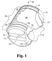
- a generally C-shaped spacer 100 is provided.
- Spacer 100 includes an elongated body 105 having an outer surface 106 and a maximum outer diameter D M .
- Elongated body 105 defines an internal, or interior, cavity 130 useful for receiving and holding graft material for promoting bone ingrowth.
- Body 105 further defines a first arm 120 and a second opposing arm 121 similar to the spacers described above.
- Arms 120, 121 define an opening, or mouth, 110 in communication with interior cavity 130.
- Arm 120 has an end 150 that is configured to form a region 170 within which an adjacent spacer can nest as best seen in Figure 1 .
- arm 121 has an end 151 that is configured to form a region 171 within which an adjacent spacer can nest.
- End 151 is preferably substantially identical to end 150.
- ends 150 and 151 are arcuately truncated. The generally concave configuration of surfaces of ends 150 and 151 are useful, for example, in allowing spacer 100 to be positioned more closely to an adjacent spacer if desired, thus allowing the surface of the ends of the arms to receive a convex surface of an adjacent spacer, and/or allows a clearance adjacent to the spacers.
- spacer 100 is generally C-shaped, having on one side thereof a wall 160 which is continuous along its entire length, whereas on the opposed side the spacer 100 lacks such a continuous wall and rather has arms 120 and 121 extending from wall 160, with ends 150 and 151 of arms 120 and 121 exposed oppositely from said wall 160.
- Spacer 100 can have all of the features of other generally C-shaped spacers, for example as disclosed in International Application Serial No. PCT/US98/11159 filed June 3, 1998 entitled OPEN INTERVERTEBRAL SPACERS, published as WO 98/55052 on December 10, 1998, which is hereby incorporated by reference in its entirety.
- spacer 100 can include a first, tool-engaging end 101 having a tool engagement hole 115 and slot 116 therein as seen in FIGS. 1 and 2 .
- Outer surface of spacer 100 can also define threaded bone-engaging portions or other surface features as described above. Threads 107 are best seen in Figure 4 .
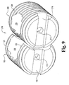
- an implant system 170 includes a first, generally C-shaped spacer 100 as described above, and a second generally C-shaped spacer 100' of similar design. Therefore, features of spacer 100' are numbered correspondingly to those of spacer 100, except with a denoting prime (') symbol.
- spacers 100 and 100' are obtained by taking a transverse plug from a diaphysis of a long bone having a medullary canal, as discussed for example in U.S. Patent No.
- the medullary canal forms at least a portion of the cavities 130 and 130' of spacers 100 and 100', respectively. Spacers 100 and 100' are also preferably threaded.
- the spacers of implant system 170 may be arranged so that spacers 100 and 100' can nest within each other. As shown in FIGS. 3-5 , the spacers may be positioned such that the opening to the cavities, or open chambers, are aligned with each other, thus forming a large, single area for optional placement of osteogenic material. In an alternative embodiment as seen in FIGS. 6-8 , spacers 100 and 100' may be positioned so that outer surface 106' of spacer 100' nests within region 170 and 171 (as best seen in Figure 1 ) formed by ends 150 and 151, respectively.
- System 270 includes a first spacer 100 as described above. Ends 150 and 151 of arms 120 and 121, respectively, of spacer 100 are configured to form a nesting region as described above within which an adjacent spacer can nest to form implant system 270. As seen in the figures, spacer 200, of differing design than spacer 100, having elongated body 204 is nested within spacer 100 to form implant system 270. That is, outer surface 206 of spacer 200 is nested within region 170 and 171 (region 170 and 171 are shown in Figure 1 ) formed by ends 150 and 151, respectively.
- implant system 270 has a width W s that is less than the sum of maximum outer diameter D M of spacer 100 and maximum outer diameter D M' of spacer 200.
- implant system 270 includes two openings 130 and 230, which can be packed with graft material to promote bone growth through the openings and arthrodesis. A first opening defined by cavity 130 of spacer 100 and external wall of spacer 200, and a second opening is provided by through-hole 230 of spacer 200.
- Spacer 200 may be a variety of spacers.
- spacer 200 may have an outer surface 206, a substantially cylindrical body 22 and a longitudinal axis.
- the spacer may include a through-hole 230, as discussed above and as depicted in FIGS. 9 and 10 .
- Spacer 200 may also be, for example, a spacer as described in U.S. Patent No. 5,814,084 .
- spacer 200 can be obtained as a transverse plug from a diaphysis of a long bone having a medullary canal, with the medullary canal forming at least a portion of the through-hole 230 in the spacer 200.
- spacer 200 can include a tool engagement hole 215 and slot 216.
- the present invention further contemplates insertion devices for facilitating the implantation of spacers, implants or bone graft.
- the tools include spacer engaging means for engaging a spacer or other item and occlusion means for blocking an opening defined in the spacer.
- FIGS. 12-15 One embodiment of an insertion tool of this invention is depicted in FIGS. 12-15 .
- Such an insertion tool is a modification of insertion tools as described in International Application Serial No. PCT/US98/11159 filed June 3, 1998 , incorporated herein by reference, having additional features as described below.
- an insertion tool 300 which includes a housing 305 having a proximal end 306 and an opposite distal end 307 and defining a passageway 310 between the two ends.
- a shaft 315 which has a first end 316 and an opposite second end 317 is disposed within the passageway 310.
- the first end 316 of the shaft 315 is adjacent the distal end 307 of the housing 305.
- the first end 316 defines a spacer engager 319.
- An occlusion member 320 is attached to the housing 305.
- the spacer engager 319 has any configuration which will engage a spacer.
- the spacer engager 319 includes a post for engaging a hole in the spacer.
- the post may have any configuration which will provide for mating engagement with a hole in a spacer.
- the post may include an engager 319 which is threaded to matingly engage a threaded tool hole.
- Other embodiments and features may include a sharply pointed tip 319 as shown, or a hexagonal shaped tip.
- the engager is shaped and sized to mate engagingly with the tool hole of the spacer.
- the spacer engaging means is a pair of prongs having opposite facing spacer engaging members for grasping an outer surface of the spacer.
- the spacer insertion tool 300 also includes an occlusion member 320 for blocking an opening defined in the spacer when the spacer engager 319 is engaged to the spacer.
- the occlusion member 320 is slideably engaged to the housing 305, and is extendible from the distal end 307 of the housing 305 for blocking an opening in the spacer.
- the occlusion member 320 closes the mouth and channel defined in the spacer 100.
- the tool 300 depicted also includes a handle portion 340.
- the handle portion includes means for slidingly moving the shaft 315 within the housing 305 and for rotating the shaft 315.
- the means includes a thumbwheel 341.
- the handle portion 340 has a Hudson end attachment 342.
- insertion tool 300 has an occlusion member 320 having an interior surface 324 which is convexly curved to complement the concave surfaces of ends 150 and 151 of arms 120 and 121, respectively, of spacer 100.
- recess 308 of insertion tool 300 has a concave surface complementary to convexly curved surface 324 of occlusion member 320.
- occlusion member 320 is of a length and design sufficient to span to the distal end of the engaged spacer 100, as depicted in Figure 15 .
- Occlusion member 320 can also have a beveled outer end, or an otherwise smoothed outer end, to facilitate rotary insertion.
- the occlusion member 320 includes a plate 321 which defines a groove 322.
- a fastener 330 is engaged to a fastener bore 309 in the housing 305 and the groove 322 is disposed around the fastener 330. in this way, the plate 321 is slideable relative to the housing 305.
- the housing 305 is preferably provided with a recess 308 which is defined to accept the occlusion member 320 without increasing the effective diameter of the device 300.
- the occlusion member is also adapted for the best fit with the spacer.
- the interior surface 324 of the occlusion member would be curved to complement the concave end faces 150 and 151 for engagement.
- the plate 321 of the occlusion member 320 preferably includes a curved superior surface 325 which approximates and completes the minor diameter of the dowel 100 when the spacer engager 319 is engaged to the tool engaging hole and the occlusion member 320 is blocking the channel of the spacer 100.
- the plate 321 and the arms 120 and 121 of the spacer 100 will be configured such that when the tool 300 is engaged to the spacer 100, the curved superior surface 325 will not increase the effective root diameter RD of the threaded outer surface of the spacer 100. This facilitates rotation and screw insertion of the spacer and occlusion member combination into an intervertebral space.
- the plate 321 defines a recess 326 surrounding a groove 322.
- a fastener 330 is engaged to a fastener bore 309 in the housing 305 and the groove 322 is disposed around the fastener 330. In this way, the plate 321 is slideable relative to the housing 305.
- the fastener 330 is preferably provided with a post 334, and a plate engaging means or head portion 335.
- the fastener 330 preferably includes an internal hex as shown for receiving a fastener driving tool.
- the post portion 334 may be threaded for mating engagement with threaded bore 309 in the housing 305.
- the diameter of the head portion 335 is greater than the diameter of the post 334.
- the diameter of the post 334 is less than the width of the groove 322.
- the diameter of the head portion is greater than width of the groove 322 but preferably no greater than the distance between the outer edges of the recess 326.
- the head portion 335 of the fastener 330 can rest on the recess 326 while the post portion 334 extends through the groove 322.
- plate 321 is slidable relative to the housing 305. This also provides for a low profile device which can be inserted into various cannula for percutaneous procedures.
- the spacers are obtained as an off-center transverse plug from the diaphysis of a long bone. This results in a dowel having an open-mouthed chamber. Because the long bone naturally includes the medullary canal, a pre-formed chamber is inherently contained within the dowel. When the plug is cut off-center in a certain way, the dowel includes an open-mouthed chamber.
- the surface features can provide engaging surfaces to facilitate engagement with the vertebrae and prevent slippage of the spacer as is sometimes seen with a smooth graft.
- the surface feature may include, for example, a groove or stop rib inscribed along the circumference of the spacer.
- the upper and lower walls of the spacers of the invention may include flattened portions to stabilize the dowel by neutralizing any rotational torque that may be induced by pressure on the sidewall.
- dowel spacers of the invention are preferably obtained from the fibula, radius, ulna or humerus.
- the dimensions of such dowels are typically between about 8-15mm in length or depth and about 10-14mm in diameter.
- the dowel is preferably obtained from the humerus, femur or tibia.
- the dimensions of such dowels are typically between about 10-30mm in length and about 14-20mm in diameter.
- the chamber may be packed with any suitable osteogenic material.
- the osteogenic composition has a length which is greater than the length of the chamber so that the osteogenic composition will contact the endplates of the adjacent vertebrae when the spacer is implanted within the vertebrae. This provides better contact of the composition with the endplates to stimulate bone ingrowth.
- osteogenic material or composition including autograft, allograft, xenograft, demineralized bone, synthetic and natural bone graft substitutes, such as bioceramics and polymers, and osteoinductive factors.
- the terms osteogenic material or osteogenic composition used here means virtually any material that promotes bone growth or healing including autograft, allograft, xenograft, bone graft substitutes and natural, synthetic and recombinant proteins, hormones and the like.
- Autograft can be harvested from locations such as the iliac crest using drills, gouges, curettes and trephines and other tools and methods which are well known to surgeons in this field.
- autograft is harvested from the iliac crest with a minimally invasive donor surgery.
- the osteogenic material may also include bone reamed away by the surgeon while preparing the end plates for the spacer.
- autograft is chosen as the osteogenic material
- only a very small amount of bone material is needed to pack the chamber.
- the autograft itself is not required to provide structural support as this is provided by the spacer.
- the donor surgery for such a small amount of bone is less invasive and better tolerated by the patient. There is usually little need for muscle dissection in obtaining such small amounts of bone.
- the present invention therefore eliminates or minimizes many of the disadvantages of employing autograft.
- Natural and synthetic graft substitutes which replace the structure or function of bone are also contemplated for the osteogenic composition. Any such graft substitute is contemplated, including for example, demineralized bone matrix, mineral compositions and bioceramics. As is evident from a review of An Introduction to Bioceramics, edited by Larry L. Hench and June Wilson (World Scientific Publishing Co. Ptd. Ltd, 1993, volume 1 ), there is a vast array of bioceramic materials, including BIOGLASS*, hydroxyapatite and calcium phosphate compositions known in the art which can be used to advantage for this purpose. That disclosure is herein incorporated by reference for this purpose. Preferred calcium compositions include bioactive glasses, tricalcium phosphates and hydroxyapatites. In one embodiment, the graft substitute is a biphasic calcium phosphate ceramic including tricalcium phosphate and hydroxyapatite.
- the osteogenic compositions used in this invention comprise a therapeutically effective amount to stimulate or induce bone growth of a substantially pure bone inductive or growth factor or protein in a pharmaceutically acceptable carrier.
- the preferred osteoinductive factors are the recombinant human bone morphogenetic proteins (rhBMPs) because they are available in unlimited supply and do not transmit infectious diseases.
- the bone morphogenetic protein is a rhBMP-2, rhBMP-4 or heterodimers thereof.
- Recombinant BMP-2 can be used at a concentration of about 0.4 mg/ml to about 1.5 mg/ml, preferably near 1.5 mg/ml.
- any bone morphogenetic protein is contemplated including bone morphogenetic proteins designated as BMP-1 through BMP-13.
- BMPs are available from Genetics Institute, Inc., Cambridge, Massachusetts and may also be prepared by one skilled in the art as described in U.S. Patent Nos. 5,187,076 to Wozney et al. ; 5,366,875 to Wozney et al. ; 4,877,864 to Wang et al. ; 5,108,922 to Wang et al. ; 5,116,738 to Wang et al.
- carrier material for the osteogenic composition is based on biocompatibility, biodegradability, mechanical properties and interface properties as well as the structure of the load bearing member.
- Potential carriers include calcium sulphates, polylactic acids, polyanhydrides, collagen, calcium phosphates, polymeric acryiic esters and demineralized bone.
- the carrier may be any suitable carrier capable of delivering the proteins. Most preferably, the carrier is capable of being eventually resorbed into the body.
- One preferred carrier is an absorbable collagen sponge marketed by Integra LifeSciences Corporation under the trade name Helistat* Absorbable Collagen Hemostatic Agent.
- Another preferred carrier is a biphasic calcium phosphate ceramic.
- Ceramic blocks are commercially available from Sofamor Danek Group, B. P. 4-62180 Rang-du-Fliers, France and Bioland, 132 Rou d Espangne, 31100 Toulouse, France.
- the osteoinductive factor is introduced into the carrier in any suitable manner.
- the carrier may be soaked in a solution containing the factor.
- a method for making an open chambered bone dowel includes obtaining an off-center plug from the diaphysis of a long bone so that the dowel has an open chamber, and machined to have inventive features as described herein, for example to have concave surfaces on each end configured to nest with an adjacent spacer, as described above.
- the open chamber is preferably substantially concave or C-shaped and has an axis that is substantially perpendicular to the long axis of the dowel.
- Appropriate human source bones include the femur, tibia, fibula, humerus, radius and ulna. Long bones from other species are also contemplated although human source bones are generally preferred for human recipients.
- the first step is to identify an acceptable donor based upon appropriate standards for the particular donor and recipient. For example, where the donor is human, some form of consent such as a donor card or written consent from the next of kin is required. Where the recipient is human, the donor must be screened for a wide variety of communicable diseases and pathogens, including human immunodeficiency virus, cytomegalovirus, hepatitis B, hepatitis C and several other pathogens. These tests may be conducted by any of a number of means conventional in the art, including but not limited to ELISA assays, PCR assays, or hemagglutination.
- the bone plugs are obtained using a diamond or hard metal tipped cutting bit which is water cleaned and cooled.
- a diamond or hard metal tipped cutting bit which is water cleaned and cooled.
- Commercially available bits e.g. core drills
- core drills having a generally circular nature and an internal vacant diameter between about 10mm to about 20 mm are amenable to use for obtention of these bone plugs.
- core drills are available, for example, from Starlite, Inc.
- a pneumatic driven miniature lathe having a spring loaded carriage which travels parallel to the cutter is used.
- the lathe has a drive system which is a pneumatic motor with a valve controller which allows a desired RPM to be set.
- the carriage rides on two runners which are 1.0 inch stainless rods and has travel distance of approximately 8.0 inches.
- One runner has set pin holes on the running rod which will stop the carriage from moving when the set pin is placed into the desired hole.
- the carriage is moveable from side to side with a knob which has graduations for positioning the graft.
- a vice on the carriage clamps the graft and holds it in place while the dowel is being cut.
- the vice has a cut-out area in the jaws to allow clearance for the cutter.
- the carriage In operation, the carriage is manually pulled back and locked in place with a set pin.
- the graft is loaded into the vice and is aligned with the cutter.
- Sterile water is used to cool and remove debris from graft and/or dowel as the dowel is being cut.
- the water travels down through the center of the cutter to irrigate as well as clean the dowel under pressure.
- sterile water is used to eject the dowel out of the cutter.
- the dowels range from 5mm to 30mm diameters with lengths of about 8mm to about 36mm being generally acceptable, although other appropriate gradations in length and diameter are available.
- lengths of 8mm, 9mm, up to about 15mm are generally desirable.
- Dowels of differing diameter are most conveniently obtained as follows: Diameter Source 10.6-11 mm fibula 12mm radius 14mm ulna 14+mm small humeri
- Dowels for thoracic and lumbar fusions such as anterior thoracic inner body fusion (ATIF) and anterior lumbar inner body fusion (ALIF) dowels, respectively, having a depth of between about 10-36 mm, and preferably between about 15-24mm, are generally acceptable, depending on the needs of a particular patient.
- Dowels of differing diameter for thoracic and lumbar fusions are most conveniently obtained as follows: Diameter Source 14-16mm humerus 16-18mm femur 18-20mm tibia While the foregoing diameters and source bones for such dowels is a useful guide, one of the significant advances provided by this invention is that the open-chambered dowel of this invention provides tremendous flexibility with respect to the source bone used.
- each dowel has the feature of having a substantially "C"-shaped chamber through the dowel perpendicular to the length of the dowel formed by the intersection of the natural intramedullary canal of the source bone and the cutter blade as it forms the plug.
- the canal cavity in the long bone is, in vivo, filled with bone marrow.
- no such natural cavity exists and the cancellous bone that forms the body of such dowels tends to be too brittle to accept machining of such a cavity.
- the dowels of this invention by the nature of their origin, inherently define such a cavity.
- the marrow is preferably removed from the intramedullary canal of the diaphysial plugs and the cavity is cleaned, leaving the chamber.
- the spacer may be provided to the surgeon with the chamber prepacked or empty for the surgeon to pack during surgery.
- the cavity or chamber can then be packed with an osteogenic material or composition.
- the plug is then machined, preferably in a class 10 clean room to the dimensions and to have the features desired.
- the machining is preferably conducted on a lathe such as a jeweler's lathe, or machining tools may be specifically designed and adapted for this purpose. Specific tolerances for the dowels and reproducibility of the product dimensions are important features for the successful use of such dowels in the clinical setting.
- the forward end of the dowel which is to be inserted into a cavity formed between adjacent vertebrae is chamfered.
- the curvature of the chamfered end facilitates insertion of the dowel into the intervertebral space.
- Chamfering can be accomplished by appropriate means such as by machining, filing, sanding or other abrasive means. The tolerance for the chamfering is fairly liberal and the desired object is merely to round or slightly point the end of the dowel that is to be inserted into the cavity formed between adjacent vertebrae to be fused.
- the invention includes methods for providing surface features into the walls of the dowels.
- the methods may include defining a tool or instrument attachment hole in an end of the dowel.
- the hole may be drilled and preferably tapped.
- the dowel will be of such dimensions as to fit standard insertion tools, such as those produced by Sofamor Danek Group, Inc. (1800 Pyramid Place, Memphis, TN 38132, (800) 933-2635).
- a score mark or driver slot may be inscribed on the instrument attachment end of the dowel so that the surgeon can align the dowel so that the chamber is parallel with the length of the recipient's spinal column. The mark or slot allows the surgeon to orient the dowel properly after the dowel is inserted and the chamber is no longer visible. In the proper orientation, the endplates of the adjacent vertebrae are exposed to osteogenic material in the chamber.
- the driver slot is omitted to preserve as much bone stock, and therefore strength, in the end as possible.
- the dowels of this invention have the advantage of having very good biomechanical properties amenable to such machining.
- the spacers and tools in this invention can be conveniently incorporated into known surgical, preferably minimally invasive, procedures.
- the spacers of this invention can be inserted using laparoscopic technology as described in Sofamor Danek USA's Laparoscopic Bone Dowel Surgical Technique, 1995, 1800 Pyramid Place, Memphis, Tennessee 38132, 1-800-933-2635 , preferably in combination with the insertion tool 300 of this invention.
- Spacers of this invention can be conveniently incorporated into Sofamor Danek's laparoscopic bone dowel system that facilitates anterior interbody fusions with an approach that is much less surgically morbid than the standard open anterior retroperitoneal approaches.
- This system includes templates, trephines, dilators, reamers, ports and other devices required for laparoscopic dowel insertion.
- a minimally invasive open anterior approach using Sofamor Danek's open anterior bone dowel instrumentation or a posterior surgical approach using Sofamor Danek's posterior approach bone dowel instrumentation are contemplated.
- the present invention also includes methods for fusing adjacent vertebrae.
- the spine may be approached from any direction indicated by the circumstances.
- the vertebrae and the intervertebral space are prepared according to conventional procedures to receive the spacer.
- a spacer of the appropriate dimensions is selected by the surgeon, based on the size of the cavity created and the needs of the particular patient undergoing the fusion.
- the spacer is mounted on an instrument, preferably via an instrument attachment hole.
- an osteogenic material is placed within the chamber of the spacer and the channel and or mouth of the spacer is then blocked with an occlusion member of the instrument.
- the spacer is then inserted into the cavity created between the adjacent vertebra to be fused.
- the spacer is oriented within the intervertebral space so the osteogenic material in the chamber is in communication with the end plates of the vertebra. Once the spacer is properly oriented within the intervertebral space, the occlusion member of the instrument can be withdrawn from the spacer aperture and the spacer engager is disengaged from the spacer.
- osteogenic material is packed into the chamber through the channel after implantation.
- a second spacer is implanted into the intervertebral space.
- the spacers of this invention can be formed of any suitable biocompatible material, including metals, ceramics, polymers, composites, alloys and the like. Some embodiments include titanium, stainless steel, and Hedrocel ® .
- differing shapes can be made from the diaphysis of various bones and can be used for orthopaedic purposes other than vertebral fusions.
- any of a number of known bone treatments can be applied to the dowel of this invention to alter its properties.
- the methods disclosed in U.S. Patent Nos. 4,627,853 ; 5,053,049 ; 5,306,303 and 5,171,279 can be adapted and applied to the invention disclosed herein. Accordingly the disclosures of those patents are herein incorporated by reference for this purpose.
Abstract
Description
- The present invention broadly concerns arthrodesis for stabilizing the spine. More specifically, the invention provides open-chambered intervertebral spacers, instruments for implanting the spacers and methods for making and using the spacers.
- Intervertebral discs, located between the endplates of adjacent vertebrae, stabilize the spine, distribute forces between vertebrae and cushion vertebral bodies. A normal intervertebral disc includes a semi-gelatinous component, the nucleus pulposus, which is surrounded and confined by an outer, fibrous ring called the annulus fibrosus. In a healthy, undamaged spine, the annulus fibrosus prevents the nucleus pulposus from protruding outside the disc space.
- Spinal discs may be displaced or damaged due to trauma, disease or aging. Disruption of the annulus fibrosus allows the nucleus pulposus to protrude into the vertebral canal, a condition commonly referred to as a herniated or ruptured disc. The extruded nucleus pulposus may press on a spinal nerve, which may result in nerve damage, pain, numbness, muscle weakness and paralysis. Intervertebral discs may also deteriorate due to the normal aging process or disease. As a disc dehydrates and hardens, the disc space height will be reduced leading to instability of the spine, decreased mobility and pain.
- Sometimes the only relief from the symptoms of these conditions is a discectomy, or surgical removal of a portion or all of an intervertebral disc followed by fusion of the adjacent vertebrae. The removal of the damaged or unhealthy disc will allow the disc space to collapse. Collapse of the disc space can cause instability of the spine, abnormal joint mechanics, premature development of arthritis or nerve damage, in addition to severe pain. Pain relief via discectomy and arthrodesis requires preservation of the disc space and eventual fusion of the affected motion segments.
- Bone grafts are often used to fill the intervertebral space to prevent disc space collapse and promote fusion of the adjacent vertebrae across the disc space. In early techniques, bone material was simply disposed between the adjacent vertebrae, typically at the posterior aspect of the vertebra, and the spinal column was stabilized by way of a plate or rod spanning the affected vertebrae. Once fusion occurred, the hardware used to maintain the stability of the segment became superfluous and was a permanent foreign body. Moreover, the surgical procedures necessary to implant a rod or plate to stabilize the level during fusion were frequently lengthy and involved.
- It was therefore determined that a more optimal solution to the stabilization of an excised disc space is to fuse the vertebrae between their respective end plates, preferably without the need for anterior or posterior plating. There have been an extensive number of attempts to develop an acceptable intradiscal implant that could be used to replace a damaged disc and maintain the stability of the disc interspace between the adjacent vertebrae, at least until complete arthrodesis is achieved. The implant must provide temporary support and allow bone ingrowth. Success of the discectomy and fusion procedure requires the development of a contiguous growth of bone to create a solid mass because the implant may not withstand the compressive loads on the spine for the life of the patient.
- Several metal spacers have been developed to fill the void formed and to promote fusion. Sofamor Danek Group, Inc., (1800 Pyramid Place, Memphis, TN 38132, (800) 933-2635) markets a number of hollow spinal cages. For example,
U.S. Patent No. 5,015,247 to Michelson andU.S. Serial No. 08/411,017 to Zdeblick disclose a threaded spinal cage. The cages are hollow and can be filled with osteogenic material, such as autograft or allograft, prior to insertion into the intervertebral space. Apertures defined in the cage communicate with the hollow interior to provide a path for tissue growth between the vertebral endplates. - Although the metal fusion devices of Sofamor Danek and others are widely and successfully employed for reliable fusions, it is sometimes desirable to use an all-bone product. Bone provides many advantages for use in fusions. It can be incorporated after fusion occurs and therefore will not be a permanent implant. Bone allows excellent postoperative imaging because it does not cause scattering like metallic implants. Stress shielding is avoided because bone grafts have a similar modulus of elasticity as the surrounding bone. Although an all-bone spacer provides these and other benefits, the use of bone presents several challenges. Any spacer which will be placed within the intervertebral disc space must withstand the cyclic loads of the spine. Cortical bone products may have sufficient compressive strength for such use, however, cortical bone will not promote rapid fusion. Cancellous bone is more conducive to fusion but is not biomechanically sound as an intervertebral spacer.
-
WO 98/55052 - According to the present invention there is provided an interbody fusion spacer, comprising: an elongated body defining a chamber, said body having a first arm and a second opposing arm, said arms defining an opening in communication with said chamber, characterised in that each of said first arm and second arm has an end configured to form a nesting region within which an adjacent spacer can nest.
- This invention provides spacers having an open chamber, tools for implanting the spacers and methods for making and using the spacers. The spacers include an elongated body defining a chamber and having a first arm and a second arm. The arms define an opening in communication with the chamber. In one preferred embodiment, the ends are substantially identical to each other. In a preferred form of the invention, the arms each have an end with a concave surface extending to the outer edge or periphery of the spacer.
- Spacers of the invention desirably have bodies composed of bone. In one aspect, the body is a dowel having a substantially C-shaped chamber and comprising an off-center bone plug obtained from the diaphysis of a long bone.
- Another aspect of the invention provides interbody fusion implant systems. In one form of the invention, the system includes two of the inventive spacers described above in nestable combination. In another form of the invention, the system includes one of the inventive spacers described above along with a second spacer nestable therewith. The second spacer may for example have an elongated body and an outer surface, and may define a through-hole that preferably extends perpendicular to the longitudinal axis of the second body.
- Tools for implanting spacers are also provided. The tools include spacer engaging means for engaging a spacer and occlusion means for blocking an opening defined in the spacer. In one aspect the engaging means includes a shaft slidingly disposed within a housing and having a threaded post for engaging a threaded tool hole in the spacer. In some embodiments, the occlusion means includes a plate extendible from the housing. In one specific embodiment the plate defines a groove which is disposed around a fastener attached to the housing so that the plate is slideable relative to the housing. In other preferred embodiments, the occlusion member has an interior and exterior surface wherein at least one of the surfaces is curved.
- This invention also includes methods for obtaining an open bone dowel and methods for using the spacers of this invention. The methods of making a dowel according to this invention include cutting an off-center plug from the diaphysis of a long bone to obtain a bone dowel having an open chamber. The dowel is machined to include desirable nestable surface features such as those described above, in addition to threads, grooves, instrument holes and the like. In still another aspect, the methods include chamfering the forward end of the dowel.
- The invention also concerns methods for using the spacers of this invention to promote fusion bone growth between adjacent vertebrae. In one form of the invention, the method for promoting fusion bone growth includes providing one of the spacers described above, preparing the adjacent vertebrae to receive the elongated body of the spacer by, for example, making a cavity between two vertebrae to be fused and implanting or otherwise placing the elongated body into the intervertebral space. In some embodiments the chamber is packed with osteogenic material before the spacer is implanted. In. other aspects of the invention, osteogenic material is packed into and around the chamber through the mouth or channel after implantation.
- The combination of the open-chambered spacers of this invention with the tools and methods of this invention provide a versatile spacer and implant systems. The spacers can be packed before or after implantation. This invention facilitates implanting a pair of open spacers close to each other in an intervertebral space.
- Accordingly, it is one object of this invention to provide nestable bone fusion spacers and methods for using the spacers in arthrodesis procedures.
- Another object of this invention is to provide a dowel for vertebral fusions which has improved properties and versatility over standard dowels known in the art.
- These and other objects, advantages and features are accomplished according to the spacers, tools and methods of the following description of the preferred embodiments of the present invention.
-
-
Figure 1 is a perspective view of an interbody fusion spacer of the present invention. -
Figure 2 is an end elevational view of the interbody fusion spacer depicted inFigure 1 . -
Figure 3 is a perspective view of an implant system including two C-shaped spacers having arcuately truncated arms. -
Figure 4 is a top elevational view of the implant system depicted inFigure 3 . -
Figure 5 is an end elevational view of the implant system depicted inFigure 3 . -
Figure 6 is a perspective view of an implant system of the present invention, showing how the spacer ofFigure 1 may be alternately positioned adjacent to another of said spacers. -
Figure 7 is a top elevational view of the implant system depicted inFigure 6 . -
Figure 8 is an end elevational view of the implant system depicted inFigure 6 . -
Figure 9 is a perspective view of an implant system including one C-shaped spacer nested with another spacer. -
Figure 10 is a top elevational view of the implant system depicted inFigure 9 . -
Figure 11 is an end elevational view of the implant system depicted inFigure 9 . -
Figure 12 is a top perspective view of one embodiment of an insertion tool of the invention. -
Figure 13 is a side perspective view of the insertion tool depicted inFigure 12 . -
Figure 14 is an exploded side perspective view of a tool-spacer assembly according to this invention. -
Figure 15 is a side perspective view of the tool-spacer assembly depicted inFigure 14 . - For the purposes of promoting an understanding of the principles of the invention, reference will now be made to the embodiments illustrated in the drawings and specific language will be used to describe the same. It will nevertheless be understood that no limitation of the scope of the invention is thereby intended, such alterations and further modifications in the illustrated device, and such further applications of the principles of the invention as illustrated therein being contemplated as would normally occur to one skilled in the art to which the invention relates.
- This invention provides spacers having an open-mouthed chamber. These spacers are advantageous for maximum exposure of vertebral tissue to osteogenic material within the chamber and allow close placement of a pair of spacers within the intervertebral space. The design of these spacers conserves material without compromising biomechanical properties of the spacer. This is particularly advantageous when the material is bone because the invention preserves precious allograft. In fact, larger dowels and other shaped grafts can be obtained from smaller bones than was ever thought possible before the present invention. Likewise, smaller dowels having a pre-formed chamber may be efficiently obtained from larger bones.
- As disclosed, one aspect of the invention provides interbody fusion spacers configured to nest with an adjacent spacer. Referring now to
Figures 1 and2 , in one embodiment, a generally C-shapedspacer 100 is provided.Spacer 100 includes anelongated body 105 having anouter surface 106 and a maximum outer diameter DM. Elongated body 105 defines an internal, or interior,cavity 130 useful for receiving and holding graft material for promoting bone ingrowth.Body 105 further defines afirst arm 120 and a secondopposing arm 121 similar to the spacers described above.Arms interior cavity 130.Arm 120 has anend 150 that is configured to form aregion 170 within which an adjacent spacer can nest as best seen inFigure 1 . Similarly,arm 121 has anend 151 that is configured to form aregion 171 within which an adjacent spacer can nest.End 151 is preferably substantially identical to end 150. In one form of the invention as seen inFigure 1 , ends 150 and 151 are arcuately truncated. The generally concave configuration of surfaces ofends spacer 100 is generally C-shaped, having on one side thereof awall 160 which is continuous along its entire length, whereas on the opposed side thespacer 100 lacks such a continuous wall and rather hasarms wall 160, withends arms wall 160. -
Spacer 100 can have all of the features of other generally C-shaped spacers, for example as disclosed inInternational Application Serial No. PCT/US98/11159 filed June 3, 1998 published as WO 98/55052 spacer 100 can include a first, tool-engagingend 101 having atool engagement hole 115 andslot 116 therein as seen inFIGS. 1 and2 . Outer surface ofspacer 100 can also define threaded bone-engaging portions or other surface features as described above. Threads 107 are best seen inFigure 4 . - In yet another aspect of the invention, interbody fusion implant systems are provided. Referring now to
FIGS. 3-5 , one form of animplant system 170 includes a first, generally C-shapedspacer 100 as described above, and a second generally C-shaped spacer 100' of similar design. Therefore, features of spacer 100' are numbered correspondingly to those ofspacer 100, except with a denoting prime (') symbol. In one mode of practicing the invention,spacers 100 and 100' are obtained by taking a transverse plug from a diaphysis of a long bone having a medullary canal, as discussed for example inU.S. Patent No. 5,814,084 entitled DIAPHYSIAL CORTICAL DOWEL, which is hereby incorporated herein by reference in its entirety, and/or in the above-citedInternational Application Serial No. PCT/US98/11159 filed June 3, 1998 cavities 130 and 130' ofspacers 100 and 100', respectively.Spacers 100 and 100' are also preferably threaded. - The spacers of
implant system 170 may be arranged so thatspacers 100 and 100' can nest within each other. As shown inFIGS. 3-5 , the spacers may be positioned such that the opening to the cavities, or open chambers, are aligned with each other, thus forming a large, single area for optional placement of osteogenic material. In an alternative embodiment as seen inFIGS. 6-8 ,spacers 100 and 100' may be positioned so that outer surface 106' of spacer 100' nests withinregion 170 and 171 (as best seen inFigure 1 ) formed byends - Referring now to
FIGS. 9-11 , depicted is anotherimplant system 270 of the present invention.System 270 includes afirst spacer 100 as described above.Ends arms spacer 100 are configured to form a nesting region as described above within which an adjacent spacer can nest to formimplant system 270. As seen in the figures,spacer 200, of differing design thanspacer 100, having elongatedbody 204 is nested withinspacer 100 to formimplant system 270. That is,outer surface 206 ofspacer 200 is nested withinregion 170 and 171 (region Figure 1 ) formed byends implant system 270 is reduced as compared to one in which two spacers of design ofspacer 200 were implanted adjacent to one another. More specifically, it can be seen thatimplant system 270 has a width Ws that is less than the sum of maximum outer diameter DM ofspacer 100 and maximum outer diameter DM' ofspacer 200. As can also be seen,implant system 270 includes twoopenings cavity 130 ofspacer 100 and external wall ofspacer 200, and a second opening is provided by through-hole 230 ofspacer 200. -
Spacer 200, may be a variety of spacers. For example,spacer 200 may have anouter surface 206, a substantiallycylindrical body 22 and a longitudinal axis. The spacer may include a through-hole 230, as discussed above and as depicted inFIGS. 9 and10 .Spacer 200 may also be, for example, a spacer as described inU.S. Patent No. 5,814,084 . Thus,spacer 200 can be obtained as a transverse plug from a diaphysis of a long bone having a medullary canal, with the medullary canal forming at least a portion of the through-hole 230 in thespacer 200. As withspacer 100,spacer 200 can include atool engagement hole 215 andslot 216. - The present invention further contemplates insertion devices for facilitating the implantation of spacers, implants or bone graft. The tools include spacer engaging means for engaging a spacer or other item and occlusion means for blocking an opening defined in the spacer. One embodiment of an insertion tool of this invention is depicted in
FIGS. 12-15 . Such an insertion tool is a modification of insertion tools as described inInternational Application Serial No. PCT/US98/11159 filed June 3, 1998 - In one embodiment, an
insertion tool 300 is provided which includes ahousing 305 having aproximal end 306 and an oppositedistal end 307 and defining apassageway 310 between the two ends. Ashaft 315 which has afirst end 316 and an oppositesecond end 317 is disposed within thepassageway 310. Thefirst end 316 of theshaft 315 is adjacent thedistal end 307 of thehousing 305. Thefirst end 316 defines aspacer engager 319. Anocclusion member 320 is attached to thehousing 305. - The
spacer engager 319 has any configuration which will engage a spacer. In some embodiments thespacer engager 319 includes a post for engaging a hole in the spacer. The post may have any configuration which will provide for mating engagement with a hole in a spacer. For example, the post may include an engager 319 which is threaded to matingly engage a threaded tool hole. Other embodiments and features may include a sharply pointedtip 319 as shown, or a hexagonal shaped tip. In each case, the engager is shaped and sized to mate engagingly with the tool hole of the spacer. In other embodiments, the spacer engaging means is a pair of prongs having opposite facing spacer engaging members for grasping an outer surface of the spacer. - The
spacer insertion tool 300 also includes anocclusion member 320 for blocking an opening defined in the spacer when thespacer engager 319 is engaged to the spacer. In a preferred embodiment, theocclusion member 320 is slideably engaged to thehousing 305, and is extendible from thedistal end 307 of thehousing 305 for blocking an opening in the spacer. Theocclusion member 320 closes the mouth and channel defined in thespacer 100. - The
tool 300 depicted also includes ahandle portion 340. The handle portion includes means for slidingly moving theshaft 315 within thehousing 305 and for rotating theshaft 315. In the embodiment shown, the means includes athumbwheel 341. In some embodiments, thehandle portion 340 has aHudson end attachment 342. - Referring now to
Figures 14 and15 , shown are expanded views illustrating aninventive spacer 100 associated with theinsertion tool 300 to form an assembly of the invention. As illustrated,insertion tool 300 has anocclusion member 320 having aninterior surface 324 which is convexly curved to complement the concave surfaces ofends arms spacer 100. Correspondingly,recess 308 ofinsertion tool 300 has a concave surface complementary to convexlycurved surface 324 ofocclusion member 320. Further,occlusion member 320 is of a length and design sufficient to span to the distal end of the engagedspacer 100, as depicted inFigure 15 .Occlusion member 320 can also have a beveled outer end, or an otherwise smoothed outer end, to facilitate rotary insertion. - Referring now to
Figure 14 , in one embodiment, theocclusion member 320 includes aplate 321 which defines agroove 322. Afastener 330 is engaged to afastener bore 309 in thehousing 305 and thegroove 322 is disposed around thefastener 330. in this way, theplate 321 is slideable relative to thehousing 305. - As shown, the
housing 305 is preferably provided with arecess 308 which is defined to accept theocclusion member 320 without increasing the effective diameter of thedevice 300. The occlusion member is also adapted for the best fit with the spacer. For example, theinterior surface 324 of the occlusion member would be curved to complement the concave end faces 150 and 151 for engagement. Theplate 321 of theocclusion member 320 preferably includes a curvedsuperior surface 325 which approximates and completes the minor diameter of thedowel 100 when thespacer engager 319 is engaged to the tool engaging hole and theocclusion member 320 is blocking the channel of thespacer 100. Preferably, theplate 321 and thearms spacer 100 will be configured such that when thetool 300 is engaged to thespacer 100, the curvedsuperior surface 325 will not increase the effective root diameter RD of the threaded outer surface of thespacer 100. This facilitates rotation and screw insertion of the spacer and occlusion member combination into an intervertebral space. - In preferred embodiments, as shown in
Figures 14 and15 , theplate 321 defines arecess 326 surrounding agroove 322. Afastener 330 is engaged to afastener bore 309 in thehousing 305 and thegroove 322 is disposed around thefastener 330. In this way, theplate 321 is slideable relative to thehousing 305. Thefastener 330 is preferably provided with apost 334, and a plate engaging means orhead portion 335. Thefastener 330 preferably includes an internal hex as shown for receiving a fastener driving tool. Thepost portion 334 may be threaded for mating engagement with threadedbore 309 in thehousing 305. In preferred embodiments, the diameter of thehead portion 335 is greater than the diameter of thepost 334. The diameter of thepost 334 is less than the width of thegroove 322. The diameter of the head portion is greater than width of thegroove 322 but preferably no greater than the distance between the outer edges of therecess 326. Thus, thehead portion 335 of thefastener 330 can rest on therecess 326 while thepost portion 334 extends through thegroove 322. In this way,plate 321 is slidable relative to thehousing 305. This also provides for a low profile device which can be inserted into various cannula for percutaneous procedures. - Although any open-chambered spacers having the inventive features described herein is contemplated, in one embodiment the spacers are obtained as an off-center transverse plug from the diaphysis of a long bone. This results in a dowel having an open-mouthed chamber. Because the long bone naturally includes the medullary canal, a pre-formed chamber is inherently contained within the dowel. When the plug is cut off-center in a certain way, the dowel includes an open-mouthed chamber.
- Other surface features can be defined along the length of the spacer. The surface features can provide engaging surfaces to facilitate engagement with the vertebrae and prevent slippage of the spacer as is sometimes seen with a smooth graft. The surface feature may include, for example, a groove or stop rib inscribed along the circumference of the spacer. In some embodiments, also, the upper and lower walls of the spacers of the invention may include flattened portions to stabilize the dowel by neutralizing any rotational torque that may be induced by pressure on the sidewall.
- For cervical fusions, dowel spacers of the invention are preferably obtained from the fibula, radius, ulna or humerus. The dimensions of such dowels are typically between about 8-15mm in length or depth and about 10-14mm in diameter. For thoracic and lumbar fusions, the dowel is preferably obtained from the humerus, femur or tibia. The dimensions of such dowels are typically between about 10-30mm in length and about 14-20mm in diameter.
- The chamber may be packed with any suitable osteogenic material. In a preferred embodiment, the osteogenic composition has a length which is greater than the length of the chamber so that the osteogenic composition will contact the endplates of the adjacent vertebrae when the spacer is implanted within the vertebrae. This provides better contact of the composition with the endplates to stimulate bone ingrowth.
- Any suitable osteogenic material or composition is contemplated, including autograft, allograft, xenograft, demineralized bone, synthetic and natural bone graft substitutes, such as bioceramics and polymers, and osteoinductive factors. The terms osteogenic material or osteogenic composition used here means virtually any material that promotes bone growth or healing including autograft, allograft, xenograft, bone graft substitutes and natural, synthetic and recombinant proteins, hormones and the like.
- Autograft can be harvested from locations such as the iliac crest using drills, gouges, curettes and trephines and other tools and methods which are well known to surgeons in this field. Preferably, autograft is harvested from the iliac crest with a minimally invasive donor surgery. The osteogenic material may also include bone reamed away by the surgeon while preparing the end plates for the spacer.
- Advantageously, where autograft is chosen as the osteogenic material, only a very small amount of bone material is needed to pack the chamber. The autograft itself is not required to provide structural support as this is provided by the spacer. The donor surgery for such a small amount of bone is less invasive and better tolerated by the patient. There is usually little need for muscle dissection in obtaining such small amounts of bone. The present invention therefore eliminates or minimizes many of the disadvantages of employing autograft.
- Natural and synthetic graft substitutes which replace the structure or function of bone are also contemplated for the osteogenic composition. Any such graft substitute is contemplated, including for example, demineralized bone matrix, mineral compositions and bioceramics. As is evident from a review of An Introduction to Bioceramics, edited by Larry L. Hench and June Wilson (World Scientific Publishing Co. Ptd. Ltd, 1993, volume 1), there is a vast array of bioceramic materials, including BIOGLASS*, hydroxyapatite and calcium phosphate compositions known in the art which can be used to advantage for this purpose. That disclosure is herein incorporated by reference for this purpose. Preferred calcium compositions include bioactive glasses, tricalcium phosphates and hydroxyapatites. In one embodiment, the graft substitute is a biphasic calcium phosphate ceramic including tricalcium phosphate and hydroxyapatite.
- In some embodiments, the osteogenic compositions used in this invention comprise a therapeutically effective amount to stimulate or induce bone growth of a substantially pure bone inductive or growth factor or protein in a pharmaceutically acceptable carrier. The preferred osteoinductive factors are the recombinant human bone morphogenetic proteins (rhBMPs) because they are available in unlimited supply and do not transmit infectious diseases. Most preferably, the bone morphogenetic protein is a rhBMP-2, rhBMP-4 or heterodimers thereof.
- Recombinant BMP-2 can be used at a concentration of about 0.4 mg/ml to about 1.5 mg/ml, preferably near 1.5 mg/ml. However, any bone morphogenetic protein is contemplated including bone morphogenetic proteins designated as BMP-1 through BMP-13. BMPs are available from Genetics Institute, Inc., Cambridge, Massachusetts and may also be prepared by one skilled in the art as described in
U.S. Patent Nos. 5,187,076 to Wozney et al. ;5,366,875 to Wozney et al. ;4,877,864 to Wang et al. ;5,108,922 to Wang et al. ;5,116,738 to Wang et al. ;5,013,649 to Wang et al. ;5,106,748 to Wozney et al. ; andPCT Patent Nos. WO93/00432 to Wozney et al. WO94/26893 to Celeste et al. WO94/26892 to Celeste et al U.S. Patent No. 4,294,753 to Urist and Urist et al., 81 PNAS 371, 1984. - The choice of carrier material for the osteogenic composition is based on biocompatibility, biodegradability, mechanical properties and interface properties as well as the structure of the load bearing member. The particular application of the compositions of the invention will define the appropriate formulation. Potential carriers include calcium sulphates, polylactic acids, polyanhydrides, collagen, calcium phosphates, polymeric acryiic esters and demineralized bone. The carrier may be any suitable carrier capable of delivering the proteins. Most preferably, the carrier is capable of being eventually resorbed into the body. One preferred carrier is an absorbable collagen sponge marketed by Integra LifeSciences Corporation under the trade name Helistat* Absorbable Collagen Hemostatic Agent. Another preferred carrier is a biphasic calcium phosphate ceramic. Ceramic blocks are commercially available from Sofamor Danek Group, B. P. 4-62180 Rang-du-Fliers, France and Bioland, 132 Rou d Espangne, 31100 Toulouse, France. The osteoinductive factor is introduced into the carrier in any suitable manner. For example, the carrier may be soaked in a solution containing the factor.
- The present invention also provides methods for making the open spacers of this invention. In one embodiment, a method for making an open chambered bone dowel includes obtaining an off-center plug from the diaphysis of a long bone so that the dowel has an open chamber, and machined to have inventive features as described herein, for example to have concave surfaces on each end configured to nest with an adjacent spacer, as described above. The open chamber is preferably substantially concave or C-shaped and has an axis that is substantially perpendicular to the long axis of the dowel. Appropriate human source bones include the femur, tibia, fibula, humerus, radius and ulna. Long bones from other species are also contemplated although human source bones are generally preferred for human recipients.
- The first step is to identify an acceptable donor based upon appropriate standards for the particular donor and recipient. For example, where the donor is human, some form of consent such as a donor card or written consent from the next of kin is required. Where the recipient is human, the donor must be screened for a wide variety of communicable diseases and pathogens, including human immunodeficiency virus, cytomegalovirus, hepatitis B, hepatitis C and several other pathogens. These tests may be conducted by any of a number of means conventional in the art, including but not limited to ELISA assays, PCR assays, or hemagglutination. Such testing follows the requirements of: (i) American Association of Tissue Banks, Technical Manual for Tissue Banking, Technical Manual- Musculoskeletal Tissues, pages M19-M20; (ii) The Food and Drug Administration, Interim Rule, Federal Register/Vol. 58, No. 238/Tuesday, December 14, 1994/Rules and Regulations/65517, D. Infectious Disease Testing and Donor Screening; (iii) MMWR/Vol. 43/No. RR-8m Guidelines for Preventing Transmission of Human Immunodeficiency Virus Through Transplantation of Human Tissue and organs, pages 4-7; (iv) Florida Administrative Weekly, Vol. 10, No. 34, August 21, 1992, 59A-1.001-01459A-1.005(12)(c), F.A.C., (12)(a)-(h), 59A-1.005 (15), F.A.C., (4)(a)-(8). In addition to a battery of standard biomechanical assays, the donor, or their next of kin, is interviewed to ascertain whether the donor engaged in any of a number of high risk behaviors such as having multiple sexual partners, suffering from hemophilia, engaging in intravenous drug use, etc. Once a donor has been ascertained to be acceptable, the bones useful for obtention of the dowels are recovered and cleaned.
- Preferably, the bone plugs are obtained using a diamond or hard metal tipped cutting bit which is water cleaned and cooled. Commercially available bits (e.g. core drills) having a generally circular nature and an internal vacant diameter between about 10mm to about 20 mm are amenable to use for obtention of these bone plugs. Such core drills are available, for example, from Starlite, Inc. In one embodiment, a pneumatic driven miniature lathe having a spring loaded carriage which travels parallel to the cutter is used. The lathe has a drive system which is a pneumatic motor with a valve controller which allows a desired RPM to be set. The carriage rides on two runners which are 1.0 inch stainless rods and has travel distance of approximately 8.0 inches. One runner has set pin holes on the running rod which will stop the carriage from moving when the set pin is placed into the desired hole. The carriage is moveable from side to side with a knob which has graduations for positioning the graft. A vice on the carriage clamps the graft and holds it in place while the dowel is being cut. The vice has a cut-out area in the jaws to allow clearance for the cutter.
- In operation, the carriage is manually pulled back and locked in place with a set pin. The graft is loaded into the vice and is aligned with the cutter. Sterile water is used to cool and remove debris from graft and/or dowel as the dowel is being cut. The water travels down through the center of the cutter to irrigate as well as clean the dowel under pressure. After the dowel is cut, sterile water is used to eject the dowel out of the cutter.
- Dowels of any size can be prepared according to this invention. In some embodiments, the dowels range from 5mm to 30mm diameters with lengths of about 8mm to about 36mm being generally acceptable, although other appropriate gradations in length and diameter are available. For cervical dowels, such as anterior cervical fusion or ACF dowels, lengths of 8mm, 9mm, up to about 15mm are generally desirable. Dowels of differing diameter are most conveniently obtained as follows:
Diameter Source 10.6-11 mm fibula 12mm radius 14mm ulna 14+mm small humeri - Dowels for thoracic and lumbar fusions, such as anterior thoracic inner body fusion (ATIF) and anterior lumbar inner body fusion (ALIF) dowels, respectively, having a depth of between about 10-36 mm, and preferably between about 15-24mm, are generally acceptable, depending on the needs of a particular patient. Dowels of differing diameter for thoracic and lumbar fusions are most conveniently obtained as follows:
Diameter Source 14-16mm humerus 16-18mm femur 18-20mm tibia - Since the spacers of the preferred embodiment are obtained from off-center transverse plugs across the diaphysis of long bones, each dowel has the feature of having a substantially "C"-shaped chamber through the dowel perpendicular to the length of the dowel formed by the intersection of the natural intramedullary canal of the source bone and the cutter blade as it forms the plug. The canal cavity in the long bone is, in vivo, filled with bone marrow. In the standard Cloward Dowel and unicortical dowels known in the art, no such natural cavity exists and the cancellous bone that forms the body of such dowels tends to be too brittle to accept machining of such a cavity. The dowels of this invention, by the nature of their origin, inherently define such a cavity. Naturally, based on this disclosure, those skilled in the art will recognize that other bone sources could be used which do not have the intramedullary canal, and if sufficient strength is inherent to the bone, a cavity or chamber could be machined. In addition, it will be appreciated from the instant disclosure that an existing diaphysial cortical dowel having a through hole, such as that depicted in
U.S. Patent No. 5,814,084 , could be modified by machining one side of such a dowel until one wall of the dowel is sufficiently abraded to "break-through", thereby transforming the diaphysial cortical dowel into a "C"-shaped dowel, and machined to incorporate the features of this invention. Accordingly, such extensions of this invention should be considered as variants of the invention disclosed herein and therefore come within the scope of the claims appended hereto. - The marrow is preferably removed from the intramedullary canal of the diaphysial plugs and the cavity is cleaned, leaving the chamber. The spacer may be provided to the surgeon with the chamber prepacked or empty for the surgeon to pack during surgery. The cavity or chamber can then be packed with an osteogenic material or composition.
- The plug is then machined, preferably in a class 10 clean room to the dimensions and to have the features desired. The machining is preferably conducted on a lathe such as a jeweler's lathe, or machining tools may be specifically designed and adapted for this purpose. Specific tolerances for the dowels and reproducibility of the product dimensions are important features for the successful use of such dowels in the clinical setting.
- In some embodiments, the forward end of the dowel which is to be inserted into a cavity formed between adjacent vertebrae is chamfered. The curvature of the chamfered end facilitates insertion of the dowel into the intervertebral space. Chamfering can be accomplished by appropriate means such as by machining, filing, sanding or other abrasive means. The tolerance for the chamfering is fairly liberal and the desired object is merely to round or slightly point the end of the dowel that is to be inserted into the cavity formed between adjacent vertebrae to be fused.
- In some embodiments, the invention includes methods for providing surface features into the walls of the dowels. The methods may include defining a tool or instrument attachment hole in an end of the dowel. The hole may be drilled and preferably tapped. Preferably, the dowel will be of such dimensions as to fit standard insertion tools, such as those produced by Sofamor Danek Group, Inc. (1800 Pyramid Place, Memphis, TN 38132, (800) 933-2635). In addition, a score mark or driver slot may be inscribed on the instrument attachment end of the dowel so that the surgeon can align the dowel so that the chamber is parallel with the length of the recipient's spinal column. The mark or slot allows the surgeon to orient the dowel properly after the dowel is inserted and the chamber is no longer visible. In the proper orientation, the endplates of the adjacent vertebrae are exposed to osteogenic material in the chamber. In some embodiments, the driver slot is omitted to preserve as much bone stock, and therefore strength, in the end as possible.
- Surface features such as grooves and threads may be preferably defined or inscribed on the outer cylindrical surface of the dowel. Machining of such features on dowels known in the art is difficult if not impossible due to the brittle cancellous nature of such dowels. Accordingly, the dowels of this invention have the advantage of having very good biomechanical properties amenable to such machining.
- Those skilled in the art will also recognize that any of a number of different means may be employed to produce the threaded or grooved embodiments of the dowel of this invention. However, one preferred embodiment of a thread cutter is described in
International Application Serial No. PCT/US98/11159 filed June 3, 1998 - The spacers and tools in this invention can be conveniently incorporated into known surgical, preferably minimally invasive, procedures. The spacers of this invention can be inserted using laparoscopic technology as described in Sofamor Danek USA's Laparoscopic Bone Dowel Surgical Technique, 1995, 1800 Pyramid Place, Memphis, Tennessee 38132, 1-800-933-2635, preferably in combination with the
insertion tool 300 of this invention. Spacers of this invention can be conveniently incorporated into Sofamor Danek's laparoscopic bone dowel system that facilitates anterior interbody fusions with an approach that is much less surgically morbid than the standard open anterior retroperitoneal approaches. This system includes templates, trephines, dilators, reamers, ports and other devices required for laparoscopic dowel insertion. Alternatively, a minimally invasive open anterior approach using Sofamor Danek's open anterior bone dowel instrumentation or a posterior surgical approach using Sofamor Danek's posterior approach bone dowel instrumentation are contemplated. - The present invention also includes methods for fusing adjacent vertebrae. The spine may be approached from any direction indicated by the circumstances. The vertebrae and the intervertebral space are prepared according to conventional procedures to receive the spacer. A spacer of the appropriate dimensions is selected by the surgeon, based on the size of the cavity created and the needs of the particular patient undergoing the fusion. The spacer is mounted on an instrument, preferably via an instrument attachment hole. In one embodiment, an osteogenic material is placed within the chamber of the spacer and the channel and or mouth of the spacer is then blocked with an occlusion member of the instrument. The spacer is then inserted into the cavity created between the adjacent vertebra to be fused. The spacer is oriented within the intervertebral space so the osteogenic material in the chamber is in communication with the end plates of the vertebra. Once the spacer is properly oriented within the intervertebral space, the occlusion member of the instrument can be withdrawn from the spacer aperture and the spacer engager is disengaged from the spacer.
- In some embodiments, osteogenic material is packed into the chamber through the channel after implantation. In still other embodiments, a second spacer is implanted into the intervertebral space.
- While the foregoing description discloses specific aspects of this invention, those skilled in the art will recognize that any of a number of variations on the basic theme disclosed herein can be made. It is contemplated that the spacers of this invention can be formed of any suitable biocompatible material, including metals, ceramics, polymers, composites, alloys and the like. Some embodiments include titanium, stainless steel, and Hedrocel®. Thus, for example, differing shapes can be made from the diaphysis of various bones and can be used for orthopaedic purposes other than vertebral fusions. In addition, any of a number of known bone treatments can be applied to the dowel of this invention to alter its properties. For example, the methods disclosed in
U.S. Patent Nos. 4,627,853 ;5,053,049 ;5,306,303 and5,171,279 can be adapted and applied to the invention disclosed herein. Accordingly the disclosures of those patents are herein incorporated by reference for this purpose. - It should be understood that the example and embodiments described herein are for illustrative purposes only and that various modifications or changes in light thereof will be suggested to persons skilled in the art and are to be included within the scope of the invention as defined in the appended claims.
Claims (28)
- An interbody fusion spacer (100), comprising:an elongated body (105) defining a chamber (130), said body having a first arm (120) and a second opposing arm (121), said arms defining an opening (110) in communication with said chamber (130), characterised in that each of said first arm (120) and second arm (121) has an end (150, 151) configured to form a nesting region (170, 171) within which an adjacent spacer can nest.
- The spacer of claim 1, wherein said body (105) further comprises a tool engaging end (101) defining a tool engaging hole (115) for receiving a driving tool for implanting the spacer.
- The spacer of claim 1, wherein said elongated body (105) is comprised of a porous material.
- The spacer of claim 1, wherein said porous material is bone.
- The spacer of claim 4, wherein said bone is cortical bone.
- The spacer of claim 4, wherein said bone is obtained as a transverse cut from the diaphysis of a long bone having a medullary canal.
- The spacer of claim 1, wherein said body (105) has an outer surface that defines threaded bone-engaging portions (107).
- The spacer of claim 1, wherein each of said ends (150, 151) has a concave surface.
- The spacer of claim 8, wherein the concave surface extends to an outer edge of the spacer (100).
- The spacer of claim 1, further comprising an osteogenic material disposed within said channel.
- The spacer of claim 10, wherein said osteogenic material comprises natural bone, demineralized bone, a calcium phosphate material, a bioceramic, bioglass, an osteoinductive factor and mixtures thereof.
- The spacer of claim 10, wherein said osteogenic material comprises a bone morphogenetic protein.
- The spacer of claim 12, wherein said bone morphogenetic protein comprises a recombinant protein.
- The spacer of claim 13, wherein said recombinant bone morphogenetic protein comprises a human protein.
- The spacer of claim 14, wherein said recombinant human protein comprises BMP-2, BMP-4 or heterodimers thereof.
- The spacer of claim 1, wherein said ends of each of said arms (120, 121) has an arcuate surface configured to receive a convex surface of an adjacent spacer.
- The spacer of claim 1, wherein the nesting region (170, 171) is arcuately truncated.
- The spacer of claim 1, in combination with an adjacent, second spacer, wherein said elongated body (105) has a first maximum outer diameter and each of said arms (120, 121) of said elongated body are configured to form a nesting region for nesting of said adjacent second spacer that has a second maximum outer diameter to form a spacer assembly having a width less than the sum of the combined maximum outer diameters.
- The spacer of claim 8, which is formed of bone.
- The spacer of claim 1, wherein said elongated body (105) has a longitudinal axis and said chamber (130) extends perpendicular to said longitudinal axis.
- An interbody fusion spacer according to claim 1, wherein:said elongated body (105) is of bone having a longitudinal axis and defining said chamber (130) extending perpendicular to said longitudinal axis of said body, said body of bone comprised of bone from the diaphysis of a long bone having a medullary canal, and said nested region (170, 171) having a concave surface.
- The spacer of claim 21, wherein said body further comprises a tool engaging end (101) defining a tool engaging hole (115) for receiving a driving tool for implanting the spacer.
- An interbody fusion spacer according to claim 1 in combination with:a second interbody fusion spacer (100', 200) having a second elongated (105', 204) body of bone and an outer surface (206), said second interbody fusion spacer (100', 200) nestable within said first interbody fusion spacer (100) within said nested regions (170, 171).
- The spacer of claim 23, wherein said second elongated body (204) defines a through-hole (230).
- The spacer of claim 24, wherein said second elongated body (204) has a longitudinal axis and said through-hole (230) extends perpendicular to said longitudinal axis.
- The spacer of claim 23, wherein said second elongated body defines a second chamber, said second body having a third arm and a fourth opposing arm, said third and fourth arms defining a second opening in communication with said second chamber, said second interbody fusion spacer nestable within said first interbody fusion spacer.
- The spacer of claim 26, said system further comprising an osteogenic material disposed in at least one of said chambers of said spacers.
- An interbody fusion spacer combination, comprising:a first interbody fusion spacer (100) according to any one of claims 1 to 22 anda second spacer (100', 200) adjacent to said first spacer (100);said second spacer (100', 200) having a second maximum outer diameter, said second spacer in nested relationship with said first spacer by having a first portion nested within a region on said first arm (120) of said first spacer and a second portion nested within a region of said second arm (121) of said first spacer;said interbody fusion spacer combination, by virtue of said nested relationship, having an overall width that is less than the sum of said first maximum outer diameter and said second maximum outer diameter.
Applications Claiming Priority (3)
| Application Number | Priority Date | Filing Date | Title |
|---|---|---|---|
| US11538899P | 1999-01-11 | 1999-01-11 | |
| US115388P | 1999-01-11 | ||
| PCT/US2000/000590 WO2000041654A2 (en) | 1999-01-11 | 2000-01-11 | Truncated open intervertebral spacers |
Publications (3)
| Publication Number | Publication Date |
|---|---|
| EP1143885A2 EP1143885A2 (en) | 2001-10-17 |
| EP1143885A3 EP1143885A3 (en) | 2002-01-02 |
| EP1143885B1 true EP1143885B1 (en) | 2008-02-27 |
Family
ID=22361073
Family Applications (3)
| Application Number | Title | Priority Date | Filing Date |
|---|---|---|---|
| EP00903218A Expired - Lifetime EP1143885B1 (en) | 1999-01-11 | 2000-01-11 | Truncated open intervertebral spacers |
| EP00908251A Expired - Lifetime EP1139930B1 (en) | 1999-01-11 | 2000-01-11 | Intervertebral spacers with side wall accessible interior cavity |
| EP05076786A Withdrawn EP1609445A1 (en) | 1999-01-11 | 2000-01-11 | Intervertebral spacers with side wall accessible interior cavity |
Family Applications After (2)
| Application Number | Title | Priority Date | Filing Date |
|---|---|---|---|
| EP00908251A Expired - Lifetime EP1139930B1 (en) | 1999-01-11 | 2000-01-11 | Intervertebral spacers with side wall accessible interior cavity |
| EP05076786A Withdrawn EP1609445A1 (en) | 1999-01-11 | 2000-01-11 | Intervertebral spacers with side wall accessible interior cavity |
Country Status (9)
| Country | Link |
|---|---|
| US (2) | US7534265B1 (en) |
| EP (3) | EP1143885B1 (en) |
| JP (2) | JP4312964B2 (en) |
| AT (2) | ATE387162T1 (en) |
| AU (2) | AU763735B2 (en) |
| CA (2) | CA2360424C (en) |
| DE (2) | DE60038160T2 (en) |
| ES (1) | ES2248049T3 (en) |
| WO (2) | WO2000041655A2 (en) |
Families Citing this family (74)
| Publication number | Priority date | Publication date | Assignee | Title |
|---|---|---|---|---|
| US7087082B2 (en) | 1998-08-03 | 2006-08-08 | Synthes (Usa) | Bone implants with central chambers |
| USRE38614E1 (en) | 1998-01-30 | 2004-10-05 | Synthes (U.S.A.) | Intervertebral allograft spacer |
| US6648895B2 (en) | 2000-02-04 | 2003-11-18 | Sdgi Holdings, Inc. | Methods and instrumentation for vertebral interbody fusion |
| EP1152697A1 (en) | 1999-02-04 | 2001-11-14 | SDGI Holdings, Inc. | Methods and instrumentation for vertebral interbody fusion |
| US6743234B2 (en) | 1999-02-04 | 2004-06-01 | Sdgi Holdings, Inc. | Methods and instrumentation for vertebral interbody fusion |
| WO2003026514A1 (en) | 1999-02-04 | 2003-04-03 | Sdgi Holdings, Inc, | Methods and instrumentation for vertebral interbody fusion |
| US6241770B1 (en) * | 1999-03-05 | 2001-06-05 | Gary K. Michelson | Interbody spinal fusion implant having an anatomically conformed trailing end |
| EP1198208B1 (en) * | 1999-05-05 | 2013-07-10 | Warsaw Orthopedic, Inc. | Nested interbody spinal fusion implants |
| FR2794967B1 (en) * | 1999-06-21 | 2001-12-14 | Medicrea | DILATORY HEAD INTRODUCED BETWEEN BONE ARTICULAR BONE SURFACES TO RESTORE THE WIDTH AND ANGULAR POSITION |
| AU7080200A (en) | 1999-08-26 | 2001-03-19 | Sdgi Holdings, Inc. | Devices and methods for implanting fusion cages |
| US6350283B1 (en) * | 2000-04-19 | 2002-02-26 | Gary K. Michelson | Bone hemi-lumbar interbody spinal implant having an asymmetrical leading end and method of installation thereof |
| US7462195B1 (en) | 2000-04-19 | 2008-12-09 | Warsaw Orthopedic, Inc. | Artificial lumbar interbody spinal implant having an asymmetrical leading end |
| WO2002009597A2 (en) * | 2000-08-01 | 2002-02-07 | Regeneration Technologies, Inc. | Diaphysial cortical dowel |
| WO2002098332A1 (en) * | 2001-02-16 | 2002-12-12 | Sulzer Spine-Tech Inc. | Bone implants and methods |
| WO2002065957A2 (en) * | 2001-02-16 | 2002-08-29 | Sulzer Spine-Tech Inc. | Bone implants and methods |
| US6989031B2 (en) * | 2001-04-02 | 2006-01-24 | Sdgi Holdings, Inc. | Hemi-interbody spinal implant manufactured from a major long bone ring or a bone composite |
| US6890355B2 (en) | 2001-04-02 | 2005-05-10 | Gary K. Michelson | Artificial contoured spinal fusion implants made of a material other than bone |
| ITVI20010128A1 (en) * | 2001-05-31 | 2002-12-01 | Bioteck Srl | BIOMEDICAL GRAFT FOR SKELETON STRUCTURES |
| US6585749B2 (en) | 2001-08-01 | 2003-07-01 | Sulzer Spine-Tech Inc. | Surgical implant instrument and method |
| ATE314828T1 (en) | 2001-09-27 | 2006-02-15 | Zimmer Spine Inc | MODULAR INTERVERBEL FUSIONATION DEVICE AND PRODUCTION METHOD THEREOF |
| AU2002330146B2 (en) * | 2001-09-28 | 2007-10-18 | Zimmer Spine, Inc. | Skeletal stabilization implant |
| AR038680A1 (en) | 2002-02-19 | 2005-01-26 | Synthes Ag | INTERVERTEBRAL IMPLANT |
| EP2335656B1 (en) | 2003-02-06 | 2012-09-05 | Synthes GmbH | Implant between vertebrae |
| US7819903B2 (en) | 2003-03-31 | 2010-10-26 | Depuy Spine, Inc. | Spinal fixation plate |
| WO2005102226A1 (en) * | 2004-04-26 | 2005-11-03 | Synthes Gmbh | Intervertebral prosthesis or disk prosthesis |
| ATE524121T1 (en) | 2004-11-24 | 2011-09-15 | Abdou Samy | DEVICES FOR PLACING AN ORTHOPEDIC INTERVERTEBRAL IMPLANT |
| WO2006107302A1 (en) * | 2005-04-04 | 2006-10-12 | Zimmer Spine, Inc. | Threaded intervertebral implant |
| EP1988855A2 (en) | 2006-02-27 | 2008-11-12 | Synthes GmbH | Intervertebral implant with fixation geometry |
| US8163026B2 (en) * | 2007-04-05 | 2012-04-24 | Zimmer Spine, Inc. | Interbody implant |
| US10821003B2 (en) | 2007-06-20 | 2020-11-03 | 3Spline Sezc | Spinal osteotomy |
| BRPI0820172A2 (en) | 2007-11-16 | 2015-06-16 | Synthes Gmbh | Low Profile Intervertebral Implant |
| US8088163B1 (en) | 2008-02-06 | 2012-01-03 | Kleiner Jeffrey B | Tools and methods for spinal fusion |
| WO2009100400A1 (en) * | 2008-02-06 | 2009-08-13 | Nuvasive, Inc. | Systems and methods for spinal fusion |
| US8915962B1 (en) * | 2008-04-24 | 2014-12-23 | Loubert S. Suddaby | Facet joint fixation device |
| USD853560S1 (en) | 2008-10-09 | 2019-07-09 | Nuvasive, Inc. | Spinal implant insertion device |
| CA2742812A1 (en) | 2008-11-07 | 2010-05-14 | William P. Mcdonough | Zero-profile interbody spacer and coupled plate assembly |
| US8366748B2 (en) | 2008-12-05 | 2013-02-05 | Kleiner Jeffrey | Apparatus and method of spinal implant and fusion |
| US9247943B1 (en) | 2009-02-06 | 2016-02-02 | Kleiner Intellectual Property, Llc | Devices and methods for preparing an intervertebral workspace |
| USD656610S1 (en) | 2009-02-06 | 2012-03-27 | Kleiner Jeffrey B | Spinal distraction instrument |
| US10973656B2 (en) | 2009-09-18 | 2021-04-13 | Spinal Surgical Strategies, Inc. | Bone graft delivery system and method for using same |
| US10245159B1 (en) | 2009-09-18 | 2019-04-02 | Spinal Surgical Strategies, Llc | Bone graft delivery system and method for using same |
| US8906028B2 (en) * | 2009-09-18 | 2014-12-09 | Spinal Surgical Strategies, Llc | Bone graft delivery device and method of using the same |
| US20170238984A1 (en) | 2009-09-18 | 2017-08-24 | Spinal Surgical Strategies, Llc | Bone graft delivery device with positioning handle |
| US9629729B2 (en) | 2009-09-18 | 2017-04-25 | Spinal Surgical Strategies, Llc | Biological delivery system with adaptable fusion cage interface |
| US9186193B2 (en) | 2009-09-18 | 2015-11-17 | Spinal Surgical Strategies, Llc | Fusion cage with combined biological delivery system |
| USD723682S1 (en) | 2013-05-03 | 2015-03-03 | Spinal Surgical Strategies, Llc | Bone graft delivery tool |
| US8685031B2 (en) | 2009-09-18 | 2014-04-01 | Spinal Surgical Strategies, Llc | Bone graft delivery system |
| US9173694B2 (en) | 2009-09-18 | 2015-11-03 | Spinal Surgical Strategies, Llc | Fusion cage with combined biological delivery system |
| USD750249S1 (en) | 2014-10-20 | 2016-02-23 | Spinal Surgical Strategies, Llc | Expandable fusion cage |
| US9060877B2 (en) | 2009-09-18 | 2015-06-23 | Spinal Surgical Strategies, Llc | Fusion cage with combined biological delivery system |
| US8979927B2 (en) * | 2009-11-18 | 2015-03-17 | Innovasis, Inc. | Spinal implant with staples |
| US8764806B2 (en) | 2009-12-07 | 2014-07-01 | Samy Abdou | Devices and methods for minimally invasive spinal stabilization and instrumentation |
| CA2793185C (en) | 2010-03-16 | 2019-02-12 | Pinnacle Spine Group, Llc | Intervertebral implants and graft delivery systems and methods |
| EP2654626B1 (en) | 2010-12-21 | 2016-02-24 | Synthes GmbH | Intervertebral implants and systems |
| US9241809B2 (en) | 2010-12-21 | 2016-01-26 | DePuy Synthes Products, Inc. | Intervertebral implants, systems, and methods of use |
| US9358122B2 (en) | 2011-01-07 | 2016-06-07 | K2M, Inc. | Interbody spacer |
| US8845728B1 (en) | 2011-09-23 | 2014-09-30 | Samy Abdou | Spinal fixation devices and methods of use |
| US9380932B1 (en) | 2011-11-02 | 2016-07-05 | Pinnacle Spine Group, Llc | Retractor devices for minimally invasive access to the spine |
| WO2013119803A1 (en) * | 2012-02-07 | 2013-08-15 | Medivest, Llc | Tissue spacer implants, insertion and adjustment tools, and method of use |
| US20130226240A1 (en) | 2012-02-22 | 2013-08-29 | Samy Abdou | Spinous process fixation devices and methods of use |
| US9198767B2 (en) | 2012-08-28 | 2015-12-01 | Samy Abdou | Devices and methods for spinal stabilization and instrumentation |
| US9320617B2 (en) | 2012-10-22 | 2016-04-26 | Cogent Spine, LLC | Devices and methods for spinal stabilization and instrumentation |
| WO2014159739A1 (en) | 2013-03-14 | 2014-10-02 | Pinnacle Spine Group, Llc | Interbody implants and graft delivery systems |
| US9867718B2 (en) | 2014-10-22 | 2018-01-16 | DePuy Synthes Products, Inc. | Intervertebral implants, systems, and methods of use |
| WO2016077606A1 (en) | 2014-11-12 | 2016-05-19 | Medivest, Llc | Spinal spacing implant, spinal spacer assembly, expander and insertion instrument, kit and methods of assembly and use |
| US10857003B1 (en) | 2015-10-14 | 2020-12-08 | Samy Abdou | Devices and methods for vertebral stabilization |
| USD797290S1 (en) | 2015-10-19 | 2017-09-12 | Spinal Surgical Strategies, Llc | Bone graft delivery tool |
| US10588750B2 (en) * | 2016-04-14 | 2020-03-17 | Cutting Edge Spine Llc | Implants and techniques for tissue fixation and fusion |
| US10744000B1 (en) | 2016-10-25 | 2020-08-18 | Samy Abdou | Devices and methods for vertebral bone realignment |
| US10973648B1 (en) | 2016-10-25 | 2021-04-13 | Samy Abdou | Devices and methods for vertebral bone realignment |
| GB2561293A (en) | 2017-03-14 | 2018-10-10 | Alphatec Spine Inc | Intervertebral Cage with porosity gradient |
| US11179248B2 (en) | 2018-10-02 | 2021-11-23 | Samy Abdou | Devices and methods for spinal implantation |
| US11540920B2 (en) * | 2019-10-17 | 2023-01-03 | Chap-Med, Inc. | Internal pedicle insulator |
| CN110693631B (en) * | 2019-10-17 | 2023-06-27 | 徐州市中心医院 | Intervertebral fusion device under inverse insertion type intervertebral foramen mirror |
Family Cites Families (32)
| Publication number | Priority date | Publication date | Assignee | Title |
|---|---|---|---|---|
| US2519811A (en) * | 1948-01-13 | 1950-08-22 | Roy H Alexander | Screw holding screw driver |
| US4736738A (en) * | 1984-07-09 | 1988-04-12 | Matej Lipovsek | Instrument kit and procedure for performing posterior lumbar interbody fusion |
| US4877020A (en) * | 1984-11-30 | 1989-10-31 | Vich Jose M O | Apparatus for bone graft |
| US5108922A (en) | 1986-07-01 | 1992-04-28 | Genetics Institute, Inc. | DNA sequences encoding BMP-1 products |
| US5013649A (en) | 1986-07-01 | 1991-05-07 | Genetics Institute, Inc. | DNA sequences encoding osteoinductive products |
| US5187076A (en) | 1986-07-01 | 1993-02-16 | Genetics Institute, Inc. | DNA sequences encoding BMP-6 proteins |
| US5106748A (en) | 1986-07-01 | 1992-04-21 | Genetics Institute, Inc. | Dna sequences encoding 5 proteins |
| US4877864A (en) | 1987-03-26 | 1989-10-31 | Genetics Institute, Inc. | Osteoinductive factors |
| US5366875A (en) | 1986-07-01 | 1994-11-22 | Genetics Institute, Inc. | Methods for producing BMP-7 proteins |
| US4714469A (en) * | 1987-02-26 | 1987-12-22 | Pfizer Hospital Products Group, Inc. | Spinal implant |
| GB8718627D0 (en) | 1987-08-06 | 1987-09-09 | Showell A W Sugicraft Ltd | Spinal implants |
| US4950296A (en) | 1988-04-07 | 1990-08-21 | Mcintyre Jonathan L | Bone grafting units |
| US5593409A (en) * | 1988-06-13 | 1997-01-14 | Sofamor Danek Group, Inc. | Interbody spinal fusion implants |
| US5015247A (en) | 1988-06-13 | 1991-05-14 | Michelson Gary K | Threaded spinal implant |
| US5423825A (en) * | 1992-06-10 | 1995-06-13 | Levine; Andrew S. | Spinal fusion instruments and methods |
| JP3509103B2 (en) * | 1994-05-23 | 2004-03-22 | スルザー スパイン−テック インコーポレイテッド | Intervertebral fusion implant |
| DE59509539D1 (en) * | 1995-03-08 | 2001-09-27 | Synthes Ag | INTERVOLBLE IMPLANT |
| US5782919A (en) * | 1995-03-27 | 1998-07-21 | Sdgi Holdings, Inc. | Interbody fusion device and method for restoration of normal spinal anatomy |
| DE69732226T2 (en) * | 1995-03-27 | 2005-12-22 | SDGI Holdings, Inc., Wilmington | SPIN-FUSION IMPLANT AND INTRODUCTION AND INSPECTION TOOLS |
| FR2724312B1 (en) * | 1995-04-21 | 1997-09-12 | Alby Albert | INTERSOMATIC SPACER |
| ES2196154T3 (en) * | 1995-06-07 | 2003-12-16 | Michelson Gary K | TRANSLATERAL VERTEBRAL IMPLANT. |
| US5766253A (en) * | 1996-01-16 | 1998-06-16 | Surgical Dynamics, Inc. | Spinal fusion device |
| US5814084A (en) | 1996-01-16 | 1998-09-29 | University Of Florida Tissue Bank, Inc. | Diaphysial cortical dowel |
| FR2747034B1 (en) * | 1996-04-03 | 1998-06-19 | Scient X | INTERSOMATIC CONTAINMENT AND MERGER SYSTEM |
| EP0955961B1 (en) * | 1996-10-23 | 2004-03-31 | SDGI Holdings, Inc. | Spinal spacer |
| HUP9700532A1 (en) * | 1997-02-28 | 1998-12-28 | Surgicraft Limited, | Implantation for fixing of vertebra spondyls |
| US6120506A (en) * | 1997-03-06 | 2000-09-19 | Sulzer Spine-Tech Inc. | Lordotic spinal implant |
| FR2762779B1 (en) * | 1997-05-05 | 2000-03-03 | Valentin Riemens | ANATOMICAL CAGE FOR INTER VERTEBRAL SPACE |
| US6033438A (en) * | 1997-06-03 | 2000-03-07 | Sdgi Holdings, Inc. | Open intervertebral spacer |
| US5904719A (en) * | 1997-07-24 | 1999-05-18 | Techsys Medical, Llc | Interbody fusion device having partial circular section cross-sectional segments |
| US6224631B1 (en) * | 1998-03-20 | 2001-05-01 | Sulzer Spine-Tech Inc. | Intervertebral implant with reduced contact area and method |
| EP1198208B1 (en) | 1999-05-05 | 2013-07-10 | Warsaw Orthopedic, Inc. | Nested interbody spinal fusion implants |
-
2000
- 2000-01-11 CA CA002360424A patent/CA2360424C/en not_active Expired - Fee Related
- 2000-01-11 EP EP00903218A patent/EP1143885B1/en not_active Expired - Lifetime
- 2000-01-11 AT AT00903218T patent/ATE387162T1/en not_active IP Right Cessation
- 2000-01-11 AU AU24995/00A patent/AU763735B2/en not_active Ceased
- 2000-01-11 AU AU29633/00A patent/AU764981B2/en not_active Ceased
- 2000-01-11 EP EP00908251A patent/EP1139930B1/en not_active Expired - Lifetime
- 2000-01-11 JP JP2000593269A patent/JP4312964B2/en not_active Expired - Fee Related
- 2000-01-11 CA CA002360422A patent/CA2360422C/en not_active Expired - Fee Related
- 2000-01-11 DE DE60038160T patent/DE60038160T2/en not_active Expired - Fee Related
- 2000-01-11 AT AT00908251T patent/ATE304335T1/en not_active IP Right Cessation
- 2000-01-11 EP EP05076786A patent/EP1609445A1/en not_active Withdrawn
- 2000-01-11 WO PCT/US2000/000604 patent/WO2000041655A2/en active IP Right Grant
- 2000-01-11 JP JP2000593268A patent/JP2002534211A/en active Pending
- 2000-01-11 DE DE60022620T patent/DE60022620T2/en not_active Expired - Fee Related
- 2000-01-11 WO PCT/US2000/000590 patent/WO2000041654A2/en active IP Right Grant
- 2000-01-11 ES ES00908251T patent/ES2248049T3/en not_active Expired - Lifetime
- 2000-04-11 US US09/869,813 patent/US7534265B1/en not_active Expired - Lifetime
-
2009
- 2009-03-20 US US12/383,191 patent/US8038714B2/en not_active Expired - Fee Related
Also Published As
| Publication number | Publication date |
|---|---|
| DE60038160T2 (en) | 2009-03-12 |
| WO2000041654A3 (en) | 2001-09-07 |
| AU2963300A (en) | 2000-08-01 |
| DE60022620D1 (en) | 2005-10-20 |
| JP2002534212A (en) | 2002-10-15 |
| ATE387162T1 (en) | 2008-03-15 |
| EP1139930A2 (en) | 2001-10-10 |
| JP2002534211A (en) | 2002-10-15 |
| WO2000041654B1 (en) | 2002-02-07 |
| AU764981B2 (en) | 2003-09-04 |
| CA2360422A1 (en) | 2000-07-20 |
| US20090254181A1 (en) | 2009-10-08 |
| CA2360422C (en) | 2008-10-07 |
| CA2360424C (en) | 2008-08-26 |
| CA2360424A1 (en) | 2000-07-20 |
| WO2000041655A3 (en) | 2000-12-07 |
| US7534265B1 (en) | 2009-05-19 |
| ES2248049T3 (en) | 2006-03-16 |
| AU2499500A (en) | 2000-08-01 |
| JP4312964B2 (en) | 2009-08-12 |
| AU763735B2 (en) | 2003-07-31 |
| EP1143885A3 (en) | 2002-01-02 |
| DE60022620T2 (en) | 2006-06-22 |
| DE60038160D1 (en) | 2008-04-10 |
| EP1609445A1 (en) | 2005-12-28 |
| WO2000041655A2 (en) | 2000-07-20 |
| WO2000041654A2 (en) | 2000-07-20 |
| ATE304335T1 (en) | 2005-09-15 |
| EP1143885A2 (en) | 2001-10-17 |
| US8038714B2 (en) | 2011-10-18 |
| EP1139930B1 (en) | 2005-09-14 |
Similar Documents
| Publication | Publication Date | Title |
|---|---|---|
| EP1143885B1 (en) | Truncated open intervertebral spacers | |
| US6695882B2 (en) | Open intervertebral spacer | |
| US5814084A (en) | Diaphysial cortical dowel | |
| JP2002534211A5 (en) | ||
| EP0955961B1 (en) | Spinal spacer | |
| US20130345815A1 (en) | Bone grafts | |
| AU2003266465B2 (en) | Intervertebral Spacers with Side Wall Accessible Interior Cavity |
Legal Events
| Date | Code | Title | Description |
|---|---|---|---|
| PUAI | Public reference made under article 153(3) epc to a published international application that has entered the european phase |
Free format text: ORIGINAL CODE: 0009012 |
|
| 17P | Request for examination filed |
Effective date: 20010726 |
|
| AK | Designated contracting states |
Kind code of ref document: A2 Designated state(s): AT BE CH CY DE DK ES FI FR GB GR IE IT LI LU MC NL PT SE |
|
| AX | Request for extension of the european patent |
Free format text: AL;LT;LV;MK;RO;SI |
|
| XX | Miscellaneous (additional remarks) |
Free format text: DERZEIT SIND DIE WIPO-PUBLIKATIONSDATEN A3 NICHT VERFUEGBAR. |
|
| PUAK | Availability of information related to the publication of the international search report |
Free format text: ORIGINAL CODE: 0009015 |
|
| AK | Designated contracting states |
Kind code of ref document: A3 Designated state(s): AT BE CH CY DE DK ES FI FR GB GR IE IT LI LU MC NL PT SE |
|
| AX | Request for extension of the european patent |
Free format text: AL;LT;LV;MK;RO;SI |
|
| 17Q | First examination report despatched |
Effective date: 20040127 |
|
| GRAP | Despatch of communication of intention to grant a patent |
Free format text: ORIGINAL CODE: EPIDOSNIGR1 |
|
| RIN1 | Information on inventor provided before grant (corrected) |
Inventor name: BURKUS, J., KENNETH Inventor name: BOYD, LAWRENCE, M. Inventor name: RAY, EDDIE, F.,III Inventor name: DORCHAK, JOHN, D. Inventor name: ESTES, BRADLEY, T. |
|
| GRAS | Grant fee paid |
Free format text: ORIGINAL CODE: EPIDOSNIGR3 |
|
| GRAA | (expected) grant |
Free format text: ORIGINAL CODE: 0009210 |
|
| AK | Designated contracting states |
Kind code of ref document: B1 Designated state(s): AT BE CH CY DE DK ES FI FR GB GR IE IT LI LU MC NL PT SE |
|
| REG | Reference to a national code |
Ref country code: GB Ref legal event code: FG4D |
|
| XX | Miscellaneous (additional remarks) |
Free format text: DERZEIT SIND DIE WIPO-PUBLIKATIONSDATEN A3 NICHT VERFUEGBAR. |
|
| REG | Reference to a national code |
Ref country code: CH Ref legal event code: EP |
|
| REG | Reference to a national code |
Ref country code: IE Ref legal event code: FG4D |
|
| REF | Corresponds to: |
Ref document number: 60038160 Country of ref document: DE Date of ref document: 20080410 Kind code of ref document: P |
|
| PG25 | Lapsed in a contracting state [announced via postgrant information from national office to epo] |
Ref country code: ES Free format text: LAPSE BECAUSE OF FAILURE TO SUBMIT A TRANSLATION OF THE DESCRIPTION OR TO PAY THE FEE WITHIN THE PRESCRIBED TIME-LIMIT Effective date: 20080607 Ref country code: FI Free format text: LAPSE BECAUSE OF FAILURE TO SUBMIT A TRANSLATION OF THE DESCRIPTION OR TO PAY THE FEE WITHIN THE PRESCRIBED TIME-LIMIT Effective date: 20080227 |
|
| NLV1 | Nl: lapsed or annulled due to failure to fulfill the requirements of art. 29p and 29m of the patents act | ||
| PG25 | Lapsed in a contracting state [announced via postgrant information from national office to epo] |
Ref country code: AT Free format text: LAPSE BECAUSE OF FAILURE TO SUBMIT A TRANSLATION OF THE DESCRIPTION OR TO PAY THE FEE WITHIN THE PRESCRIBED TIME-LIMIT Effective date: 20080227 |
|
| PG25 | Lapsed in a contracting state [announced via postgrant information from national office to epo] |
Ref country code: BE Free format text: LAPSE BECAUSE OF FAILURE TO SUBMIT A TRANSLATION OF THE DESCRIPTION OR TO PAY THE FEE WITHIN THE PRESCRIBED TIME-LIMIT Effective date: 20080227 |
|
| ET | Fr: translation filed | ||
| PG25 | Lapsed in a contracting state [announced via postgrant information from national office to epo] |
Ref country code: SE Free format text: LAPSE BECAUSE OF FAILURE TO SUBMIT A TRANSLATION OF THE DESCRIPTION OR TO PAY THE FEE WITHIN THE PRESCRIBED TIME-LIMIT Effective date: 20080527 Ref country code: PT Free format text: LAPSE BECAUSE OF FAILURE TO SUBMIT A TRANSLATION OF THE DESCRIPTION OR TO PAY THE FEE WITHIN THE PRESCRIBED TIME-LIMIT Effective date: 20080721 Ref country code: DK Free format text: LAPSE BECAUSE OF FAILURE TO SUBMIT A TRANSLATION OF THE DESCRIPTION OR TO PAY THE FEE WITHIN THE PRESCRIBED TIME-LIMIT Effective date: 20080227 Ref country code: NL Free format text: LAPSE BECAUSE OF FAILURE TO SUBMIT A TRANSLATION OF THE DESCRIPTION OR TO PAY THE FEE WITHIN THE PRESCRIBED TIME-LIMIT Effective date: 20080227 |
|
| REG | Reference to a national code |
Ref country code: CH Ref legal event code: PUE Owner name: WARSAW ORTHOPEDIC, INC. Free format text: SDGI HOLDINGS, INC.#300 DELAWARE AVENUE, SUITE 508#WILMINGTON, DE 19801 (US) -TRANSFER TO- WARSAW ORTHOPEDIC, INC.#2500 SILVEUS CROSSING#WARSAW, IN 46581 (US) |
|
| PLBE | No opposition filed within time limit |
Free format text: ORIGINAL CODE: 0009261 |
|
| STAA | Information on the status of an ep patent application or granted ep patent |
Free format text: STATUS: NO OPPOSITION FILED WITHIN TIME LIMIT |
|
| 26N | No opposition filed |
Effective date: 20081128 |
|
| PG25 | Lapsed in a contracting state [announced via postgrant information from national office to epo] |
Ref country code: CY Free format text: LAPSE BECAUSE OF FAILURE TO SUBMIT A TRANSLATION OF THE DESCRIPTION OR TO PAY THE FEE WITHIN THE PRESCRIBED TIME-LIMIT Effective date: 20080227 |
|
| PG25 | Lapsed in a contracting state [announced via postgrant information from national office to epo] |
Ref country code: MC Free format text: LAPSE BECAUSE OF NON-PAYMENT OF DUE FEES Effective date: 20090131 Ref country code: IT Free format text: LAPSE BECAUSE OF FAILURE TO SUBMIT A TRANSLATION OF THE DESCRIPTION OR TO PAY THE FEE WITHIN THE PRESCRIBED TIME-LIMIT Effective date: 20080227 |
|
| REG | Reference to a national code |
Ref country code: CH Ref legal event code: PL |
|
| GBPC | Gb: european patent ceased through non-payment of renewal fee |
Effective date: 20090111 |
|
| PG25 | Lapsed in a contracting state [announced via postgrant information from national office to epo] |
Ref country code: CH Free format text: LAPSE BECAUSE OF NON-PAYMENT OF DUE FEES Effective date: 20090131 Ref country code: LI Free format text: LAPSE BECAUSE OF NON-PAYMENT OF DUE FEES Effective date: 20090131 Ref country code: DE Free format text: LAPSE BECAUSE OF NON-PAYMENT OF DUE FEES Effective date: 20090801 |
|
| REG | Reference to a national code |
Ref country code: FR Ref legal event code: ST Effective date: 20091030 |
|
| PG25 | Lapsed in a contracting state [announced via postgrant information from national office to epo] |
Ref country code: GB Free format text: LAPSE BECAUSE OF NON-PAYMENT OF DUE FEES Effective date: 20090111 |
|
| PG25 | Lapsed in a contracting state [announced via postgrant information from national office to epo] |
Ref country code: IE Free format text: LAPSE BECAUSE OF NON-PAYMENT OF DUE FEES Effective date: 20090112 |
|
| PG25 | Lapsed in a contracting state [announced via postgrant information from national office to epo] |
Ref country code: FR Free format text: LAPSE BECAUSE OF NON-PAYMENT OF DUE FEES Effective date: 20090202 |
|
| PG25 | Lapsed in a contracting state [announced via postgrant information from national office to epo] |
Ref country code: GR Free format text: LAPSE BECAUSE OF FAILURE TO SUBMIT A TRANSLATION OF THE DESCRIPTION OR TO PAY THE FEE WITHIN THE PRESCRIBED TIME-LIMIT Effective date: 20080528 |
|
| PG25 | Lapsed in a contracting state [announced via postgrant information from national office to epo] |
Ref country code: LU Free format text: LAPSE BECAUSE OF NON-PAYMENT OF DUE FEES Effective date: 20090111 |