EP1154084A2 - Wall-mounted basin - Google Patents
Wall-mounted basin Download PDFInfo
- Publication number
- EP1154084A2 EP1154084A2 EP01111646A EP01111646A EP1154084A2 EP 1154084 A2 EP1154084 A2 EP 1154084A2 EP 01111646 A EP01111646 A EP 01111646A EP 01111646 A EP01111646 A EP 01111646A EP 1154084 A2 EP1154084 A2 EP 1154084A2
- Authority
- EP
- European Patent Office
- Prior art keywords
- basin
- lance
- passage
- shower
- preamble
- Prior art date
- Legal status (The legal status is an assumption and is not a legal conclusion. Google has not performed a legal analysis and makes no representation as to the accuracy of the status listed.)
- Withdrawn
Links
Images


Classifications
-
- E—FIXED CONSTRUCTIONS
- E03—WATER SUPPLY; SEWERAGE
- E03D—WATER-CLOSETS OR URINALS WITH FLUSHING DEVICES; FLUSHING VALVES THEREFOR
- E03D9/00—Sanitary or other accessories for lavatories ; Devices for cleaning or disinfecting the toilet room or the toilet bowl; Devices for eliminating smells
- E03D9/08—Devices in the bowl producing upwardly-directed sprays; Modifications of the bowl for use with such devices ; Bidets; Combinations of bowls with urinals or bidets; Hot-air or other devices mounted in or on the bowl, urinal or bidet for cleaning or disinfecting
-
- E—FIXED CONSTRUCTIONS
- E03—WATER SUPPLY; SEWERAGE
- E03C—DOMESTIC PLUMBING INSTALLATIONS FOR FRESH WATER OR WASTE WATER; SINKS
- E03C1/00—Domestic plumbing installations for fresh water or waste water; Sinks
- E03C1/12—Plumbing installations for waste water; Basins or fountains connected thereto; Sinks
- E03C1/32—Holders or supports for basins
- E03C1/322—Holders or supports for basins connected to the wall only
-
- E—FIXED CONSTRUCTIONS
- E03—WATER SUPPLY; SEWERAGE
- E03D—WATER-CLOSETS OR URINALS WITH FLUSHING DEVICES; FLUSHING VALVES THEREFOR
- E03D11/00—Other component parts of water-closets, e.g. noise-reducing means in the flushing system, flushing pipes mounted in the bowl, seals for the bowl outlet, devices preventing overflow of the bowl contents; devices forming a water seal in the bowl after flushing, devices eliminating obstructions in the bowl outlet or preventing backflow of water and excrements from the waterpipe
- E03D11/13—Parts or details of bowls; Special adaptations of pipe joints or couplings for use with bowls, e.g. provisions in bowl construction preventing backflow of waste-water from the bowl in the flushing pipe or cistern, provisions for a secondary flushing, for noise-reducing
- E03D11/14—Means for connecting the bowl to the wall, e.g. to a wall outlet
Definitions
- the invention is based on wall-mounted basins, such as washing, bidet, washing and toilet bowls, e.g. a toilet bowl with attached cleaning shower, which can be activated by means of a retractable lance or a toilet seat with integrated under-shower and integrated odor extraction.
- wall-mounted basins such as washing, bidet, washing and toilet bowls, e.g. a toilet bowl with attached cleaning shower, which can be activated by means of a retractable lance or a toilet seat with integrated under-shower and integrated odor extraction.
- Well-known toilet bowl with shower attachment and odor extraction installed behind it have the disadvantage that they protrude very far into the room; they are very massive at all. It is also in the known versions not possible to use a concealed cistern. Furthermore are, due to the complex construction, the acquisition costs very much high. Known toilet seats with integrated showers are very unsightly and due to the complex construction and electronics also very expensive. Furthermore are they are not equipped with individual functions and cannot be retrofitted.
- the basin is similar, but the basin is one Apron molded on the back, to which it is attached using fastening screws is attachable.
- the invention is based on one object, the sanitary objects mentioned so that e.g. all fittings in the basin disappear and also that e.g. shower device and odor extraction housed inside the toilet can be.
- this is made possible by the fact that the Fastening parts inside the objects to be fastened disappear, so that e.g. the side walls of the toilet bowl are not inwards because of the Fastening screw are pulled, but run straight, so that in the Enough space inside the normal toilet bowl or the bowl body has to accommodate the shower device and the odor extraction.
- Another object of the invention is an advantageous attachment of Sanitary basin on the wall.
- the fastening parts advantageously have two square bars on e.g. either attachable to the pre-wall installation system or to can be pegged to the masonry itself.
- the square bars have in the Middle in longitudinal direction e.g. almost one over the entire length of the bar Passage.
- the walls delimiting the passage are vertical to one another opposite rows of teeth formed.
- the fastening parts for a shower device and an odor extraction plug-in are e.g. the fastening parts for a shower device and an odor extraction plug-in. So you can depending on Request only the shower device or only the odor extraction or both fasten together on the square bars or leave them out at the moment and retrofit later.
- the attachment part to the aforementioned systems To attach consists of a square that goes into the passage of the rods fits and which has also formed vertical rows of teeth on two sides with which can be locked in the passage by means of the rows of teeth. At the end of the row of teeth A small web is formed on the passage so that the square is not can fail. A screw is formed on the square, facing downwards protrudes from the passage and on the above mentioned by means of a nut Systems are attachable.
- a square with vertically formed rows of teeth can also be used, however not a screw, but a piston.
- In the piston is a vertical one Thread embedded. Above the circumference and over his Length becomes a hollow cylinder, the inner wall of which at the top ends in one Inbus passes, inserted.
- the outer wall of the hollow cylinder is eccentric for drilling.
- a toilet bowl is for example the following: First the aforementioned functional units by means of the square bolts with the molded thread mounted on the square bars, then the toilet bowl pushed over the square bars and inserted into the flushing pipe and waste water pipe and pressed against the wall at the same time. Now two square bolts with the molded piston by two recessed in the toilet bowl Holes (which, for example, are used to attach the toilet seat to known toilets) in the square bars inserted, and with such a distance to the rear Hole wall, so that the eccentric hollow cylinder with the thinner wall fits in. Then the hollow cylinders are inserted and by means of An Allen key turns the thicker wall of the hollow cylinder backwards rotated and thereby pressed the toilet bowl against the wall. Now the toilet bowl attached to the wall. The fixings of the toilet seat are in the Thread of the piston screwed in.
- the fixing rods are for a wash basin, sink, bidet or other objects extended accordingly.
- a sink is the following: the sink is pushed over the fastening rods, which are turned so that the rows of teeth are horizontal.
- the sink are like the toilet bowl Mounting holes let in, but for optical reasons on the on both sides of the sink.
- the sink will start not pushed up to the wall, but with a distance of approx. 20 cm two formed on the square bolt and extended and in Piston adjusted to the diameter of the holes in the wash basin locked.
- the flexible supply lines can then be used without great effort the valve is connected to the cold and hot water connections, so is the flexible sewage pipe.
- the locking bolts removed and the sink pressed against the wall and as before attached the toilet. Be in the threads of the square bolt with the piston Cover caps screwed in.
- the shower device which is used for cleaning the anal area after the Bowel movement is deliberately simple and comes down to the on and off switch of the odor extraction and water temperature control without electronics and is therefore cheaper to manufacture than the known ones.
- the boiler for tempering the shower water is also an open one System, so that no separate safety device is required.
- the shower lance is pushed out with water pressure, like the following Construction, however, has the disadvantage that the shower water coexists the extending shower lance spurted out, making it back up splashes, the water splashes while the lances are retracted out until it is fully retracted.
- the shower water only sprays from the lance, when it comes out and arrives at the destination.
- This is e.g. possible that the lance in a cylindrical, closed at the end Capsule is stored.
- the end of the capsule is on the holder of the Functional unit attached and has a wall in front of it Passage to which a pipe or hose is mounted and with which a Valve is connected.
- there are two directly adjacent Culverts located about 2/3 of the lance guide away from the first culvert on which in turn pipes or hoses are attached and with are connected to the hot water boiler.
- the lance has a tube with the shower head turned on one end and at the other end a cylindrical one closed at the end Capsule with a side opening is formed.
- the passage is between two positioned on its circumference arranged sealing rings.
- the use of the shower facility results from the following:
- the water now flows into the capsule and pushes the lance out to the second passage.
- the lance remains in this position by the pending Pressure of the water flowing through it; this now flows through the second passage into the hot water boiler and presses the heated water out of this through a pipe or hose into the third passage and from there into the passage of the cylindrical capsule closed at the end the shower lance into the lance tube and through the spray head of the lance. So can do not spray water before the lance extends to its destination is.
- the valve becomes brought into the closed position by means of a spring and the compression spring the lance guide pushes the lance back into the starting position.
Abstract
Description
Die Erfindung geht aus von wandhängenden Becken, wie Wasch-, Bidet-, Spül- und WC-Becken, z.B. einem WC-Becken mit angebauter Reinigungsdusche, welche mittels einer herausfahrbaren Lanze aktivierbar ist, bzw. einem WC-Sitz mit integrierter Unterdusche und einer integrierten Geruchsabsaugung.The invention is based on wall-mounted basins, such as washing, bidet, washing and toilet bowls, e.g. a toilet bowl with attached cleaning shower, which can be activated by means of a retractable lance or a toilet seat with integrated under-shower and integrated odor extraction.
Bekannten WC-Becken mit dahinter angebauter Duscheinrichtung und Geruchsabsaugung haben den Nachteil, dass sie sehr weit in den Raum hineinragen; sie sind überhaupt sehr wuchtig. Auch ist es bei den bekannten Ausführungen nicht möglich, einen Unterputzspülkasten zu verwenden. Des Weiteren sind, bedingt durch die aufwendige Konstruktion, die Anschaffungskosten sehr hoch. Bekannten WC-Sitze mit integrierter Dusche sind sehr unansehnlich und durch die aufwendige Konstruktion und Elektronik auch sehr teuer. Ferner sind sie auch nicht mit einzelnen Funktionen ausgestattet und nicht nachrüstbar.Well-known toilet bowl with shower attachment and odor extraction installed behind it have the disadvantage that they protrude very far into the room; they are very massive at all. It is also in the known versions not possible to use a concealed cistern. Furthermore are, due to the complex construction, the acquisition costs very much high. Known toilet seats with integrated showers are very unsightly and due to the complex construction and electronics also very expensive. Furthermore are they are not equipped with individual functions and cannot be retrofitted.
Bei den bekannten wandhängenden Sanitärobjekten sind die Gestaltungsmöglichkeiten eng gehalten, da man z.B. an einem WC-Becken die Befestigungsschrauben und das Herankommen mit einem Schraubenschlüssel berücksichtigen muss, ebenso bei einem Bidet, bei welchem noch erschwerend hinzu kommt, dass man noch Raum für die Warm- und Kaltwasserversorgungsröhrchen der Armatur beansprucht. Dadurch bedingt sind die Flankenwandungen eines WC- und eines Bidet-Beckens bisher zur Wand hin nach innen verzogen. The design options are known for the wall-mounted sanitary objects kept tight because e.g. the fastening screws on a toilet bowl and consider getting there with a wrench must, also with a bidet, in which still add to it comes that there is still room for the hot and cold water supply tubes of the valve. The flank walls are caused by this of a toilet and a bidet basin previously moved inwards towards the wall.
Beim Waschbecken verhält es sich ähnlich, jedoch ist dem Waschbecken eine Schürze auf der Rückseite angeformt, an dem es mittels Befestigungsschrauben befestigbar ist.The basin is similar, but the basin is one Apron molded on the back, to which it is attached using fastening screws is attachable.
Der Erfindung liegt als eine Aufgabe zu Grunde, die genannten Sanitärobjekte so zu gestalten, dass z.B. alle Armaturenteile im Becken verschwinden und ebenso dass z.B. Duschvorrichtung und Geruchsabsaugung im WC-Inneren untergebracht werden können.The invention is based on one object, the sanitary objects mentioned so that e.g. all fittings in the basin disappear and also that e.g. Shower device and odor extraction housed inside the toilet can be.
Gemäß einem ersten Aspekt der Erfindung wird dies dadurch möglich, dass die Befestigungsteile im Inneren der zu befestigenden Objekte verschwinden, so dass z.B. beim WC-Becken die Flankenwandungen nicht nach innen wegen der Befestigungsschraube gezogen sind, sondern gerade verlaufen, so dass man im Inneren des normalen WC-Beckens bzw. dem Beckenkörper genügend Raum hat, um die Duscheinrichtung und die Geruchsabsaugung unterzubringen.According to a first aspect of the invention, this is made possible by the fact that the Fastening parts inside the objects to be fastened disappear, so that e.g. the side walls of the toilet bowl are not inwards because of the Fastening screw are pulled, but run straight, so that in the Enough space inside the normal toilet bowl or the bowl body has to accommodate the shower device and the odor extraction.
Eine andere Aufgabe der Erfindung liegt in einer vorteilhaften Befestigung von Sanitärbecken an der Wand.Another object of the invention is an advantageous attachment of Sanitary basin on the wall.
Die Befestigungsteile weisen zu diesem Zweck vorteilhafterweise zwei Vierkantstäbe auf, die z.B. entweder am Vorwandinstallationssystem befestigbar oder an dem Mauerwerk selbst verdübelbar sind. Die Vierkantstäbe haben dabei in der Mitte in Längsrichtung z.B. fast über die gesamte Stablänge verlaufend einen Durchlass. Den den Durchlass begrenzenden Wandungen sind vertikale einander gegenüberliegende Zahnreihen angeformt. In den Durchlass mit den beidseitig angeformten Zahnreihen sind z.B. die Befestigungsteile für eine Duschvorrichtung und eine Geruchsabsaugung einsteckbar. So kann man je nach Wunsch nur die Duschvorrichtung oder nur die Geruchsabsaugung oder beides zusammen an den Vierkantstäben befestigen oder auch im Moment noch weglassen und später nachrüsten. Das Befestigungsteil, um die vorgenannten Systeme zu befestigen, besteht aus einem Vierkant, der in den Durchlass der Stäbe passt und der ebenfalls vertikal auf zwei Seiten Zahnreihen angeformt hat, mit dem er mittels der Zahnreihen im Durchlass arretierbar ist. Am Zahnreihenende des Durchlasses ist ein kleiner Steg angeformt, so dass der Vierkant nicht durchfallen kann. An dem Vierkant ist eine Schraube angeformt, die nach unten aus dem Durchlass herausragt und an der mittels einer Mutter die vorgenannten Systeme befestigbar sind. Für die Wandbefestigung des Beckens selbst ist z.B. ebenfalls ein Vierkant mit vertikal angeformten Zahnreihen einsetzbar, jedoch ist keine Schraube, sondern ein Kolben angeformt. In dem Kolben ist vertikal ein Gewinde eingelassen. Über dem Koben auf seinem Umfang und über seine Länge wird ein Hohlzylinder, dessen Innenwandung am oberen Ende in einen Inbus übergeht, gesteckt. Die Außenwandung des Hohlzylinder ist exzentrisch zur Bohrung.For this purpose, the fastening parts advantageously have two square bars on e.g. either attachable to the pre-wall installation system or to can be pegged to the masonry itself. The square bars have in the Middle in longitudinal direction e.g. almost one over the entire length of the bar Passage. The walls delimiting the passage are vertical to one another opposite rows of teeth formed. In the passage with the two-sided molded rows of teeth are e.g. the fastening parts for a shower device and an odor extraction plug-in. So you can depending on Request only the shower device or only the odor extraction or both fasten together on the square bars or leave them out at the moment and retrofit later. The attachment part to the aforementioned systems To attach, consists of a square that goes into the passage of the rods fits and which has also formed vertical rows of teeth on two sides with which can be locked in the passage by means of the rows of teeth. At the end of the row of teeth A small web is formed on the passage so that the square is not can fail. A screw is formed on the square, facing downwards protrudes from the passage and on the above mentioned by means of a nut Systems are attachable. For the wall mounting of the pool itself, e.g. a square with vertically formed rows of teeth can also be used, however not a screw, but a piston. In the piston is a vertical one Thread embedded. Above the circumference and over his Length becomes a hollow cylinder, the inner wall of which at the top ends in one Inbus passes, inserted. The outer wall of the hollow cylinder is eccentric for drilling.
Der Ablauf der Montage z.B. eines WC-Beckens ist bspw. folgender: Zuerst werden die vorgenannten Funktionseinheiten mittels der Vierkantbolzen mit dem angeformten Gewinde an die Vierkantstäbe montiert, dann wird das WC-Becken über die Vierkantstäbe geschoben und in das Spülrohr und Abwasserrohr eingeschoben und gleichzeitig an die Wand gedrückt. Nun werden zwei Vierkantbolzen mit dem angeformten Kolben durch zwei im WC-Becken eingelassene Löcher (die z.B. bei bekannten WC der Befestigung des WC-Sitzes dienen) in die Vierkantstäbe eingesteckt, und zwar mit einem solchen Abstand zur hinteren Lochwandung, so dass der exzentrische Hohlzylinder mit der dünneren Wandung hineinpasst. Anschließend werden die Hohlzylinder eingesteckt und mittels eines Inbusschlüssels wird die dickere Wandung des Hohlzylinders nach hinten gedreht und dadurch das WC-Becken an die Wand gepresst. Nun ist das WC-Becken an der Wand befestigt. Die Befestigungen des WC-Sitzes werden in die Gewinde des Kolbens eingedreht. The assembly process e.g. A toilet bowl is for example the following: First the aforementioned functional units by means of the square bolts with the molded thread mounted on the square bars, then the toilet bowl pushed over the square bars and inserted into the flushing pipe and waste water pipe and pressed against the wall at the same time. Now two square bolts with the molded piston by two recessed in the toilet bowl Holes (which, for example, are used to attach the toilet seat to known toilets) in the square bars inserted, and with such a distance to the rear Hole wall, so that the eccentric hollow cylinder with the thinner wall fits in. Then the hollow cylinders are inserted and by means of An Allen key turns the thicker wall of the hollow cylinder backwards rotated and thereby pressed the toilet bowl against the wall. Now the toilet bowl attached to the wall. The fixings of the toilet seat are in the Thread of the piston screwed in.
Sollte eine Drehung des Hohlzylinders nicht ausreichen, um das WC an die Wand zu pressen, so kann man den Vierkantbolzen wieder herausziehen und eine oder mehrere Zahnreihen weiter wieder einstecken oder auch zurücksetzen.If one turn of the hollow cylinder is not sufficient to connect the toilet to the Press wall, so you can pull out the square bolt and Insert or reset one or more rows of teeth again.
Bei einem Wasch-, Spül-, Bidetbecken oder anderen Objekten sind die Befestigungsvierkantstäbe entsprechend verlängert.The fixing rods are for a wash basin, sink, bidet or other objects extended accordingly.
Der Ablauf der Montage z. B. eines Waschbeckens ist folgender: Das Waschbecken wird über die Befestigungsstäbe geschoben, welche so gedreht sind, dass die Zahnreihen horizontal liegen. In dem Waschbecken sind wie am WC-Becken Befestigungslöcher eingelassen, die sich jedoch aus optischen Gründen auf den beiden Seiten des Waschbeckens befinden. Das Waschbecken wird zunächst nicht bis zur Wand geschoben, sondern mit einem Abstand von ca. 20 cm mittels zweier an den Vierkantbolzen angeformten und verlängerten und im Durchmesser den Löchern des Waschbeckens angepassten Kolben arretiert. Anschließend können ohne große Anstrengungen die flexiblen Versorgungsleitungen der Armatur mit den Kalt- und Warmwasseranschlüssen verbunden werden, so auch das flexible Abwasserrohr. Ist dies geschehen, werden die Arretierbolzen entfernt und das Waschbecken an die Wand gedrückt und wie vor das WC befestigt. In die Gewinde des Vierkantbolzen mit dem Kolben werden Abdeckkappen eingedreht.The sequence of assembly z. B. a sink is the following: the sink is pushed over the fastening rods, which are turned so that the rows of teeth are horizontal. In the sink are like the toilet bowl Mounting holes let in, but for optical reasons on the on both sides of the sink. The sink will start not pushed up to the wall, but with a distance of approx. 20 cm two formed on the square bolt and extended and in Piston adjusted to the diameter of the holes in the wash basin locked. The flexible supply lines can then be used without great effort the valve is connected to the cold and hot water connections, so is the flexible sewage pipe. When this is done, the locking bolts removed and the sink pressed against the wall and as before attached the toilet. Be in the threads of the square bolt with the piston Cover caps screwed in.
Bei dieser Art der Befestigung verschwinden alle Versorgungs-, Abwasserleitungen und Funktionseinheiten im Becken und somit sind die Becken wesentlich ansehnlicher und auch die designerischen Gestaltungsmöglichkeiten sind weit aus größer.With this type of fastening, all supply and sewage pipes disappear and functional units in the pool and thus the pools are essential handsome and the design options are also wide from bigger.
Die Duschvorrichtung, welche für das Reinigen des Analbereiches nach dem Stuhlgang verantwortlich ist, ist bewusst einfach konstruiert und kommt bis auf den Ein- und Ausschalter der Geruchsabsaugung und der Wassertemperierung ohne Elektronik aus und ist damit kostengünstiger als die bekannten herzustellen. Auch ist der Boiler für die Temperierung des Duschwassers ein offenes System, so dass keine gesonderte Sicherheitseinrichtung erforderlich ist. Bei den bekannten abgespeckten Versionen des WC-Sitzes mit integrierten Dusche wird die Duschlanze mit Wasserdruck herausgedrückt, wie auch die folgende Konstruktion, hat jedoch den Nachteil, dass das Duschwasser gleichzeitig mit der ausfahrenden Duschlanze heraus spritzt, so dass es den Rücken hoch spritzt, ebenso spritzt das Wasser während dem Einfahren der Lanzen noch heraus, bis sie ganz eingefahren ist.The shower device, which is used for cleaning the anal area after the Bowel movement is deliberately simple and comes down to the on and off switch of the odor extraction and water temperature control without electronics and is therefore cheaper to manufacture than the known ones. The boiler for tempering the shower water is also an open one System, so that no separate safety device is required. At the well-known slimmed-down versions of the toilet seat with integrated shower the shower lance is pushed out with water pressure, like the following Construction, however, has the disadvantage that the shower water coexists the extending shower lance spurted out, making it back up splashes, the water splashes while the lances are retracted out until it is fully retracted.
Gemäß diesem Aspekt der Erfindung spritzt das Duschwasser erst aus der Lanze, wenn diese herausgefahren und am Bestimmungsort angelangt ist. Dies ist z.B. dadurch möglich, dass die Lanze in einer zylindrischen, am Ende geschlossenen Kapsel gelagert ist. Die Kapsel ist mit deren Ende an der Halterung der Funktionseinheit befestigt und hat unmittelbar davor in der Wandung einen Durchlass, an dem ein Rohr oder Schlauch anmontiert ist und mit welcher ein Ventil verbunden ist. Weiterhin sind zwei unmittelbar nebeneinander liegende Durchlässe, die etwa 2/3 der Lanzenführung vom ersten Durchlass entfernt angeordnet, an denen wiederum Rohre oder Schläuche anmontiert sind und mit dem Warmwasserboiler verbunden sind.According to this aspect of the invention, the shower water only sprays from the lance, when it comes out and arrives at the destination. This is e.g. possible that the lance in a cylindrical, closed at the end Capsule is stored. The end of the capsule is on the holder of the Functional unit attached and has a wall in front of it Passage to which a pipe or hose is mounted and with which a Valve is connected. Furthermore, there are two directly adjacent Culverts located about 2/3 of the lance guide away from the first culvert on which in turn pipes or hoses are attached and with are connected to the hot water boiler.
Die Lanze weist ein Rohr auf, an dessen einem Ende der Brausekopf aufgedreht und an dessen anderem Ende eine am Ende geschlossene zylindrische Kapsel mit seitlichem Durchlass angeformt ist. Der Durchlass ist zwischen zwei auf seinen Umfang angeordneten Dichtringen positioniert. Um das Rohr der Lanze und dem, dem Lanzenende angeformten Zylinder und dem Zylinder, in dem die Lanze gelagert ist, ist eine Druckfeder aufgelegt, die für das Wiedereinfahren der Lanze sorgt. The lance has a tube with the shower head turned on one end and at the other end a cylindrical one closed at the end Capsule with a side opening is formed. The passage is between two positioned on its circumference arranged sealing rings. To the pipe of the Lance and the cylinder formed on the lance end and the cylinder in to which the lance is mounted, a compression spring is placed on it for retraction the lance provides.
Die Benutzung der Duscheinrichtung ergibt sich aus Folgendem: Der Benutzer zieht an einem seitlichen durch die WC-Wandung durchgeführten Hebel und öffnet damit ein im Inneren des WC-Beckens befestigtes Ventil, das mit dem Durchlass der zylindrischen am Ende geschlossenen Kapsel verbunden .ist. Das Wasser strömt nun in die Kapsel und drückt die Lanze heraus bis zum zweiten Durchlass. Die Lanze bleibt in dieser Stellung durch den anstehenden Druck des durchströmenden Wassers stehen; dieses strömt nun durch den zweiten Durchlass in den Warmwasserboiler und drückt das erwärmte Wasser aus diesem heraus durch ein Rohr oder einen Schlauch in den dritten Durchlass und von dort in den Durchlass der am Ende geschlossenen zylindrischen Kapsel der Duschlanze in das Lanzenrohr und durch den Spritzkopf der Lanze. So kann kein Wasser herausspritzen, bevor die Lanze bis zum Bestimmungsort herausgefahren ist. Lässt der Benutzer nach dem Reinigen den Griff los, wird das Ventil mittels einer Feder in die geschlossene Stellung gebracht und die Druckfeder der Lanzenführung drückt die Lanze in die Ausgangsstellung zurück.The use of the shower facility results from the following: The user pulls on a lever and through the side of the toilet wall opens a valve attached to the inside of the toilet bowl that connects with the Passage of the cylindrical capsule closed at the end is connected. The water now flows into the capsule and pushes the lance out to the second passage. The lance remains in this position by the pending Pressure of the water flowing through it; this now flows through the second passage into the hot water boiler and presses the heated water out of this through a pipe or hose into the third passage and from there into the passage of the cylindrical capsule closed at the end the shower lance into the lance tube and through the spray head of the lance. So can do not spray water before the lance extends to its destination is. If the user releases the handle after cleaning, the valve becomes brought into the closed position by means of a spring and the compression spring the lance guide pushes the lance back into the starting position.
Durch die Art der Führung der Wasserströme kann sich kein Überdruck sich im Boiler aufbauen, da es sich in dieser Anschlussart um einen sogenannten "offenen Boiler" handelt. Auch beim Erwärmen des Wassers kann kein Druckaufbau stattfinden, da das Ausdehnungswasser ungehindert durch den dritten Durchlass an der Lanze vorbei in das WC fließen kann. Dadurch bedingt sind keine besonderen Sicherheitseinrichtungen notwendig.Due to the way the water flows, no excess pressure can build up in the Set up the boiler, as this type of connection is a so-called "open Boiler "acts. Even when heating the water can not build up pressure take place because the expansion water is unhindered by the third passage can flow past the lance into the toilet. There are none due to this special safety devices necessary.
Die Geruchsabsaugung zieht mittels eines Ventilators die Luft aus der WC-Schüssel
durch einen gesonderten Durchlass, oder an dem Durchlass, welcher
für die Lanze eingeformt ist, an dieser vorbei in den Ventilator und dieser drückt
die Luft in einen Lüftungsrohranschluss, welcher sich im Inneren des WC-Beckens
befindet oder durch einen Kohlefilter und durch mehrere Bohrungen,
die sich an der Unterseite des WC befinden. Der Kohlefilter ist für die Geruchsvernichtung
zuständig und lässt sich durch ein Auszieh- und Einschubfach, welches
der Unterseite des WC angeformt und angebracht ist, wechseln. Der Ein-
und Ausschalter für den Ventilator und den Boiler befindet sich in dem Griff, mit
welchem man das Ventil betätigt, oder sie sind an der WC-Außenwandung positioniert.
Weitere Ziele, Merkmale, Vorteile und Anwendungsmöglichkeiten der Erfindung
ergeben sich aus der nachfolgenden Beschreibung von Ausführungsbeispielen
anhand der Zeichnung. Dabei bilden alle beschriebenen oder dargestellten
Merkmale für sich oder beliebiger Kombination den Gegenstand der Erfindung
auch unabhängig von ihrer Zusammenfassung in einzelnen Ansprüchen oder
deren Rückbeziehung.
- Fig. 1
- zeigt in der Perspektive eine Beckenbefestigung in ihren Einzelteilen
mit einem
Vierkantstab 1, der in diesem Fall an einer (nicht dargestellten) Mauer verdübelbar ist, und einDurchlass 2 mitZahnreihen 3, die einander gegenüberliegend an den Innenflächen der denDurchlass 2 begrenzenden Längswandungen angeformt sind. EinVierkantbolzen 4 mit einemangeformten Gewinde 5 undZahnreihen 6 ist in denDurchlass 2 einsteckbar. An solchenVierkantbolzen 4 sind Duschvorrichtung oder Luftabsaugvorrichtung befestigbar. Damit derVierkantbolzen 4 nicht durchfallen kann, ist am unteren Ende derZahnreihen 6 eine Lippe angeformt. Einweiterer Vierkantbolzen 7 hat einen angeformten Kolben 8 mit einemeingelassenen Gewinde 9. EinHohlzylinder 10 hat eine exzentrische Bohrung, welche an einem Ende in einen Inbus 11 mündet. - Fig. 2
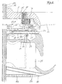
- zeigt im Schnitt einen Teil eines wandhängenden WC-
Beckens 12mit dem Vierkantstab 1, der hier an einem Vorwandinstallationssystem anmontiert und durch eine Beplankung 13mit Fliesen 14 geführt ist.Das Becken 12 liegt aufdem Vierkantstab 1 und dessen Schallschutzisolierung 13 auf und ist mittels des eingesteckten Vierkantbolzen 7 und des eingesteckten exzentrischen Hohlzylinders 10 mit Hilfe eines Imbuswerkzeugs an die Wand anpressbar.Ein Ventil 16 mit einerKaltwasseranschlussleitung 17 und einer Druckfeder 18 sowie ein andem Ventil 16abgehendes Verbindungsrohr 19, das ander Duschlanzenführung 20 und an dessen radialen Durchlass 21 anmontiert ist, sind bei 15 gezeigt.Die Verbindungsrohre mit einem Warmwasserboiler 24 verbunden. Inder Duschlanzenführung 20ist eine Duschlanze 25 gelagert mit einem aufgedrehten Brausekopf 26 und auf der anderen Seite einer angeformten zylindrischen, am Boden geschlossene Kapsel 27mit radialen Durchlässen 28 und den links und rechts davon auf dem Kapselumfang aufgelegten Dichtringen 29.Eine Druckfeder 30 drückt dieDuschlanze 25 indie Duschlanzenführung 20 zurück. (Die Duscheinrichtung ist, wegen der zeichnerisch besseren Darstellung,vor dem Ventil 16 gezeichnet, ist aber in Wirklichkeithinter dem Ventil 16 in der Mitte des WC-Beckens 12 angeordnet). Das WC-Becken 12 hat ein angeformtes oder anmontiertes Schubfach, indem ein Kohlefilter 32 steckt, und angeformte Durchlässe 33. - Fig. 3
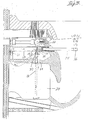
zeigt das Becken 12 wie vor, jedochmit ausgefahrener Duschlanze 25, die durch folgenden Ablauf aus der Duschlanzenführung 20 herausgedrückt wird: Wird das Ventil 16 (zeichnerisch nicht dargestellt) durch den Benutzer geöffnet, strömt das Wasser von diesem durchdas Verbindungsrohr 19durch den Durchlass 21der Lanzenführung 20 in diese und drückt dieDuschlanze 25 aus der Lanzenführung 20 heraus, bisein zweiter Durchlass 34 frei ist und strömt nun durch diesen mittels des Verbindungsrohres 22 in den Warmwasserboiler und drückt das erwärmte Wasser aus diesem heraus durchdas Verbindungsrohr 23 zu einem dritten Durchlass 35, durch diesen inden radialen Durchlass 28der Duschlanze 25 in die Lanze selbst und tritt andem Brausekopf 26 heraus.- Fig. 4
- zeigt in Draufsicht teilweise aufgeschnitten des WC-
Beckens 12mit ausgefahrener Duschlanze 25 und den beidenVierkantstäben 1 mit dem eingesteckten exzentrischen Hohlzylinder 10 undden Inbus 11sowie das Ventil 16 mit Griff 35'. - Fig. 5
- zeigt in Vorderansicht eine beflieste Wand mit den beiden
Befestigungsvierkantstäben 1,den Spülrohranschluss 36 undden Abwasseranschluss 37, die für die Montage des WC-Beckens vorgesehen sind. Anden Befestigungsvierkantstäben 1 sind mittels der eingesteckten Vierkantbolzen 4 die Halterung 37' für die Duschvorrichtung,das Ventil 16 undden Warmwasserboiler 24 sowie einer Halterung für einenVentilator 38 und dessen Abluftrohr 39, das biszu dem Kohlefilter 32 führt, gehalten. - Fig. 6
- zeigt wie vor entsprechend Fig. 5, jedoch im Schnitt das montierte
WC-
Becken mit Flankenwandungen 40, die nicht wie bei bekannten WC-Becken wegen deren Befestigungen nach innen verzogen sind, sondern gerade verlaufen, so dass man die Duscheinrichtung und Luftabsaugvorrichtung in dem WC-Becken verdeckt unterbringen kann. - Fig. 7
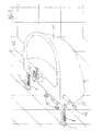
- zeigt in
Perspektive ein Waschbecken 41, das in einem verfliesten Raum mit den beidenVierkantstäben 1 montiert ist, die an dem Vorwandinstallationssystem angebracht sind und so aus der Wand herausragen, dass dieangeformten Zahnreihen 3 für diesen Fall horizontal ausgerichtet sind. Der Ablauf der Montage des Waschbeckens 41 ist folgender: Zuerstwird das Waschbecken 41 überdie beiden Vierkantstäbe 1 geschoben und mittels zwei Vierkantbolzenmit angeformtem Griff 42, welche jeweils durch ein linkes und rechtes Loch in den Waschbeckenseiten indie Vierkantstäbe 1 eingesteckt werden, arretiert, so dassdas Waschbecken 1 noch einen Abstand von ca. 20 cm zur Wand hat. So kann man (ohne dass man am Boden knien muss, wie bei den bekannten Waschbecken)eine Waschbeckenarmatur 43 montieren und deren flexiblen Versorgungsleitungen 44 mit den Warm-und Kaltwasseranschlüssen 45 verbinden, ebenso das flexible Ablaufrohr (nicht sichtbar). Sind diese Arbeiten abgeschlossen, werden die Vierkantbolzen mit dem angeformtenGriff 42 wieder entfernt unddas Waschbecken 41 an die Wand geschoben und mittels der einsteckbaren Vierkantbolzen 4 unddem exzentrischen Hohlzylinder 10 wie vor bei dem WC-Becken 12 an die Wand gepresst. Anschließend werden die Löcher indem Waschbecken 41 mit einerAbdeckkappe 46, welche indas Gewinde 9 des Einsteckbolzens 8 eindrehbar ist, verdeckt. Somit sind alle Versorgungs- und Abwasserleitungen verdeckt und auch die designerischen Gestaltungsmöglichkeiten sind größer.
Further objectives, features, advantages and possible uses of the invention result from the following description of exemplary embodiments with reference to the drawing. All of the features described or illustrated, individually or in any combination, form the subject matter of the invention, regardless of their summary in individual claims or their relationship.
- Fig. 1
- shows in perspective a basin attachment in its individual parts with a
square rod 1, which in this case can be anchored to a wall (not shown), and apassage 2 with rows ofteeth 3, which are formed opposite one another on the inner surfaces of the longitudinal walls delimiting thepassage 2 . Asquare bolt 4 with a moldedthread 5 and rows ofteeth 6 can be inserted into thepassage 2. Shower device or air suction device can be attached to suchsquare bolts 4. So that thesquare bolt 4 cannot fall through, a lip is formed on the lower end of the rows ofteeth 6. Anothersquare bolt 7 has an integrally formed piston 8 with an embeddedthread 9. Ahollow cylinder 10 has an eccentric bore which opens into anAllen key 11 at one end. - Fig. 2
- shows in section a part of a wall-hung
toilet bowl 12 with thesquare bar 1, which is mounted here on a pre-wall installation system and is guided through apaneling 13 withtiles 14. Thebasin 12 rests on thesquare rod 1 and itssound insulation 13 and can be pressed against the wall by means of the insertedsquare bolt 7 and the inserted eccentrichollow cylinder 10 using an Allen key. Avalve 16 with a coldwater connection line 17 and a compression spring 18 as well as a connectingpipe 19 going out on thevalve 16, which is mounted on theshower lance guide 20 and on itsradial passage 21, are shown at 15. The connectingpipes shower lance guide 20 and both are connected to ahot water boiler 24. In theshower lance guide 20, ashower lance 25 is mounted with ashower head 26 turned on and on the other side a molded cylindrical, closed capsule 27 on the bottom withradial passages 28 and the sealing rings 29 placed on the left and right of the capsule circumference. Acompression spring 30 presses itShower lance 25 back into theshower lance guide 20. (Because of the better representation in the drawing, the shower device is drawn in front of thevalve 16, but is actually arranged behind thevalve 16 in the middle of the toilet bowl 12). Thetoilet bowl 12 has a molded or fitted drawer in which acarbon filter 32 is inserted and moldedpassages 33. - Fig. 3
- shows the
basin 12 as before, but with theshower lance 25 extended, which is pushed out of theshower lance guide 20 by the following procedure: If the valve 16 (not shown in the drawing) is opened by the user, the water flows from it through the connectingpipe 19 through thepassage 21 of thelance guide 20 in this and presses theshower lance 25 out of thelance guide 20 until asecond passage 34 is free and now flows through this by means of the connectingpipe 22 into the hot water boiler and presses the heated water out of it through the connectingpipe 23 to onethird passage 35, through this into theradial passage 28 of theshower lance 25 into the lance itself and emerges from theshower head 26. - Fig. 4
- shows a top view partially cut away of the
toilet bowl 12 with theextended shower lance 25 and the twosquare bars 1 with the inserted eccentrichollow cylinder 10 and theAllen 11 and thevalve 16 with handle 35 '. - Fig. 5
- shows a front view of a tiled wall with the two
square fastening rods 1, theflush pipe connection 36 and thewaste water connection 37, which are provided for the assembly of the toilet bowl. The mounting 37 'for the shower device, thevalve 16 and thehot water boiler 24 as well as a mounting for afan 38 and itsexhaust pipe 39, which leads to thecarbon filter 32, are held on the mountingsquare rods 1 by means of the insertedsquare bolts 4. - Fig. 6
- shows as before according to Fig. 5, but in section, the assembled toilet bowl with
flank walls 40, which are not warped because of their fastenings inward as in known toilet bowls, but run straight, so that the shower device and air extraction device in the toilet - Can conceal the pool. - Fig. 7
- shows in perspective a
sink 41, which is mounted in a tiled room with the twosquare bars 1, which are attached to the pre-wall installation system and protrude from the wall so that the moldedteeth rows 3 are aligned horizontally for this case. The assembly of thewash basin 41 is as follows: First, thewash basin 41 is pushed over the twosquare bars 1 and locked by means of two square bolts with moldedhandles 42, which are inserted into thesquare bars 1 through a left and right hole in the sides of the wash basin, so that thesink 1 is still about 20 cm from the wall. So you can (without having to kneel on the floor, as in the known sink) mount a sink fitting 43 and connect its flexible supply lines 44 to the hot andcold water connections 45, as well as the flexible drain pipe (not visible). Once this work has been completed, the square bolts are removed again with the moldedhandle 42 and thewash basin 41 is pushed onto the wall and pressed against the wall by means of the insertablesquare bolts 4 and the eccentrichollow cylinder 10 as before in thetoilet bowl 12. The holes in thewash basin 41 are then covered with acover cap 46 which can be screwed into thethread 9 of the insert bolt 8. This means that all supply and sewage pipes are covered and the design options are also greater.
- 11
- Vierkant(stäbe)Square (rods)
- 22nd
- Durchlasspassage
- 33rd
- ZahnreihenRows of teeth
- 44th
- VierkantbolzenSquare bolt
- 55
- Gewindethread
- 66
- ZahnreihenRows of teeth
- 77
- VierkantbolzenSquare bolt
- 88th
- Kolbenpiston
- 99
- Gewindethread
- 1010th
- HohlzylinderHollow cylinder
- 1111
- ImbusIn the bus
- 1212th
- (WC-)Becken(Toilet) basin
- 1313
- Beplankungplanking
- 1414
- FliesenTiles
- 1515
- VentilanordnungValve arrangement
- 1616
- VentilValve
- 1717th
- KaltwasseranschlussleitungCold water connection pipe
- 1818th
- DruckfederCompression spring
- 1919th
- VerbindungsrohrConnecting pipe
- 2020th
- DuschlanzenführungShower lance guide
- 2121
- Durchlasspassage
- 2222
- VerbindungsrohrConnecting pipe
- 2323
- VerbindungsrohrConnecting pipe
- 2424th
- WarmwasserboilerHot water boiler
- 2525th
- DuschlanzeShower lance
- 2626
- BrausekopfShower head
- 2727
- Kapselcapsule
- 2828
- Durchlässe Culverts
- 2929
- DichtringeSealing rings
- 3030th
- DruckfederCompression spring
- 3131
- Becken mit SchubfachBasin with drawer
- 3232
- KohlefilterCarbon filter
- 3333
- DurchlässeCulverts
- 3434
- Durchlasspassage
- 3535
- Durchlasspassage
- 35'35 '
- GriffHandle
- 3636
- SpülrohranschlussFlush pipe connection
- 3737
- AbwasseranschlussSewage connection
- 37'37 '
- Halterungbracket
- 3838
- Ventilatorfan
- 3939
- AbflussrohrDrain pipe
- 4040
- FlankenwandungenFlank walls
- 4141
- (Wasch-)becken(Sink
- 4242
- GriffHandle
- 4343
- WaschbeckenarmaturWashbasin tap
- 4444
- VersorgungsleitungenSupply lines
- 4545
- Warm- und KaltwasseranschlüsseHot and cold water connections
- 4646
- AbdeckkappeCover cap
Claims (14)
Applications Claiming Priority (2)
| Application Number | Priority Date | Filing Date | Title |
|---|---|---|---|
| DE10024186 | 2000-05-13 | ||
| DE2000124186 DE10024186A1 (en) | 2000-05-13 | 2000-05-13 | Wall-hung basins |
Publications (2)
| Publication Number | Publication Date |
|---|---|
| EP1154084A2 true EP1154084A2 (en) | 2001-11-14 |
| EP1154084A3 EP1154084A3 (en) | 2002-04-10 |
Family
ID=7642404
Family Applications (1)
| Application Number | Title | Priority Date | Filing Date |
|---|---|---|---|
| EP01111646A Withdrawn EP1154084A3 (en) | 2000-05-13 | 2001-05-14 | Wall-mounted basin |
Country Status (2)
| Country | Link |
|---|---|
| EP (1) | EP1154084A3 (en) |
| DE (1) | DE10024186A1 (en) |
Cited By (3)
| Publication number | Priority date | Publication date | Assignee | Title |
|---|---|---|---|---|
| DE10163776A1 (en) * | 2001-12-22 | 2003-07-03 | Fischer Artur Werke Gmbh | Fastening fitting for a sanitary fixture |
| CN104019264A (en) * | 2014-06-25 | 2014-09-03 | 吕央赛 | Tap with rotatable water outlet pipe |
| AT522573A4 (en) * | 2019-12-10 | 2020-12-15 | Andre Rathammer | Arrangement for the installation and assembly of a wash basin |
Families Citing this family (2)
| Publication number | Priority date | Publication date | Assignee | Title |
|---|---|---|---|---|
| DE10210494C1 (en) * | 2002-03-11 | 2003-12-11 | Mepa Pauli Und Menden Gmbh | Carrier frame for wall-mounted sanitary fitting has complementary surface structures of guide rails and sliding fixing plate used for supporting weight of sanitary fitting during height adjustment |
| DE202007017328U1 (en) | 2007-12-12 | 2008-02-28 | Villeroy & Boch Ag | Device for fixing a wall-hung object |
Citations (1)
| Publication number | Priority date | Publication date | Assignee | Title |
|---|---|---|---|---|
| US4488321A (en) * | 1983-04-18 | 1984-12-18 | Brunton Bruce A | Concealed recessed urinal |
Family Cites Families (5)
| Publication number | Priority date | Publication date | Assignee | Title |
|---|---|---|---|---|
| DE1954897A1 (en) * | 1968-11-04 | 1970-09-24 | Milk Marketing Board Thames Di | Process for concentrating and desalting whey and skimmed milk |
| FR2161574A5 (en) * | 1971-11-17 | 1973-07-06 | Coutellier Paul | |
| DE3208803C2 (en) * | 1982-03-11 | 1984-02-02 | Riedinger Metallbau GmbH & Co KG, 8904 Friedberg | Mechanical connection of components |
| DE29517092U1 (en) * | 1995-10-28 | 1995-12-14 | Niro Plan Ag | Closure for the service opening of a sanitary device or a cladding / formwork of such |
| DE29821964U1 (en) * | 1998-12-09 | 1999-02-04 | Robert Hug Gmbh | Sanitary facility |
-
2000
- 2000-05-13 DE DE2000124186 patent/DE10024186A1/en active Pending
-
2001
- 2001-05-14 EP EP01111646A patent/EP1154084A3/en not_active Withdrawn
Patent Citations (1)
| Publication number | Priority date | Publication date | Assignee | Title |
|---|---|---|---|---|
| US4488321A (en) * | 1983-04-18 | 1984-12-18 | Brunton Bruce A | Concealed recessed urinal |
Cited By (4)
| Publication number | Priority date | Publication date | Assignee | Title |
|---|---|---|---|---|
| DE10163776A1 (en) * | 2001-12-22 | 2003-07-03 | Fischer Artur Werke Gmbh | Fastening fitting for a sanitary fixture |
| CN104019264A (en) * | 2014-06-25 | 2014-09-03 | 吕央赛 | Tap with rotatable water outlet pipe |
| AT522573A4 (en) * | 2019-12-10 | 2020-12-15 | Andre Rathammer | Arrangement for the installation and assembly of a wash basin |
| AT522573B1 (en) * | 2019-12-10 | 2020-12-15 | Andre Rathammer | Arrangement for the installation and assembly of a wash basin |
Also Published As
| Publication number | Publication date |
|---|---|
| DE10024186A1 (en) | 2001-11-29 |
| EP1154084A3 (en) | 2002-04-10 |
Similar Documents
| Publication | Publication Date | Title |
|---|---|---|
| EP2986787B1 (en) | Toilet with personal shower integrated into flushing water distributor | |
| EP2067901B2 (en) | Device with a flushing device and a WC body, installation set for installation of such a device and method for installing the device | |
| EP2568089B1 (en) | Use of a shower toilet connection device and of a shower toilet | |
| WO2012051729A1 (en) | Technical unit for a sanitary fixture | |
| EP1491693A2 (en) | Water-closet | |
| EP3748094B1 (en) | Shower-wc having safety device preventing suction of dirty water into the fresh water pipe | |
| EP4089240A2 (en) | Toilet flushing module and toilet | |
| DE202013001133U1 (en) | WC with shower | |
| EP3444408B1 (en) | Toilet with flushing water connection | |
| EP1154084A2 (en) | Wall-mounted basin | |
| DE102014109276B4 (en) | Toilet module with concealed cistern for a shower toilet with integrated, secured fresh water connection | |
| DE102009005319B4 (en) | Multifunctional toilet arrangement | |
| EP3670772B1 (en) | Wc connection device for connecting a shower wc to the wall and method for installing a shower wc using a wc connection device | |
| EP3321430B1 (en) | Fixing of a covering plate of an inspection aperture | |
| EP2310580B1 (en) | Sanitary apparatus comprising mixer, sanitary appliance and coupling | |
| AT519178B1 (en) | Arrangement for the installation and wall mounting of a sink or the like | |
| EP0166234B1 (en) | Connection box for water supply installations | |
| EP1457608B1 (en) | Shower arrangement | |
| DE202014009170U1 (en) | rinsing unit | |
| EP0790359B1 (en) | Fastening device for a sanitary article | |
| DE102012211655A1 (en) | Shower toilet, has shower arm arranged in region of upper end of toilet bowl, and overflow aperture that is spaced from lowest point of shower arm when overflow aperture is inserted into interior space | |
| DE4120768A1 (en) | Wall urinal with rearwards flushing water inlet and outlet connections - has water input and/or outlet connection adjustable in height | |
| DE19510228A1 (en) | Fastening device of a cistern | |
| AT522573B1 (en) | Arrangement for the installation and assembly of a wash basin | |
| EP0482506A1 (en) | Installation system |
Legal Events
| Date | Code | Title | Description |
|---|---|---|---|
| PUAI | Public reference made under article 153(3) epc to a published international application that has entered the european phase |
Free format text: ORIGINAL CODE: 0009012 |
|
| AK | Designated contracting states |
Kind code of ref document: A2 Designated state(s): AT BE CH CY DE DK ES FI FR GB GR IE IT LI LU MC NL PT SE TR |
|
| AX | Request for extension of the european patent |
Free format text: AL;LT;LV;MK;RO;SI |
|
| PUAL | Search report despatched |
Free format text: ORIGINAL CODE: 0009013 |
|
| AK | Designated contracting states |
Kind code of ref document: A3 Designated state(s): AT BE CH CY DE DK ES FI FR GB GR IE IT LI LU MC NL PT SE TR |
|
| AX | Request for extension of the european patent |
Free format text: AL;LT;LV;MK;RO;SI |
|
| AKX | Designation fees paid | ||
| REG | Reference to a national code |
Ref country code: DE Ref legal event code: 8566 |
|
| STAA | Information on the status of an ep patent application or granted ep patent |
Free format text: STATUS: THE APPLICATION IS DEEMED TO BE WITHDRAWN |
|
| 18D | Application deemed to be withdrawn |
Effective date: 20021011 |