EP1154941B1 - Modular belt with tapered oblong hinge pins - Google Patents
Modular belt with tapered oblong hinge pins Download PDFInfo
- Publication number
- EP1154941B1 EP1154941B1 EP99927532A EP99927532A EP1154941B1 EP 1154941 B1 EP1154941 B1 EP 1154941B1 EP 99927532 A EP99927532 A EP 99927532A EP 99927532 A EP99927532 A EP 99927532A EP 1154941 B1 EP1154941 B1 EP 1154941B1
- Authority
- EP
- European Patent Office
- Prior art keywords
- belt
- hinge
- row
- region
- hinge pin
- Prior art date
- Legal status (The legal status is an assumption and is not a legal conclusion. Google has not performed a legal analysis and makes no representation as to the accuracy of the status listed.)
- Expired - Lifetime
Links
Images


Classifications
-
- B—PERFORMING OPERATIONS; TRANSPORTING
- B65—CONVEYING; PACKING; STORING; HANDLING THIN OR FILAMENTARY MATERIAL
- B65G—TRANSPORT OR STORAGE DEVICES, e.g. CONVEYORS FOR LOADING OR TIPPING, SHOP CONVEYOR SYSTEMS OR PNEUMATIC TUBE CONVEYORS
- B65G17/00—Conveyors having an endless traction element, e.g. a chain, transmitting movement to a continuous or substantially-continuous load-carrying surface or to a series of individual load-carriers; Endless-chain conveyors in which the chains form the load-carrying surface
- B65G17/06—Conveyors having an endless traction element, e.g. a chain, transmitting movement to a continuous or substantially-continuous load-carrying surface or to a series of individual load-carriers; Endless-chain conveyors in which the chains form the load-carrying surface having a load-carrying surface formed by a series of interconnected, e.g. longitudinal, links, plates, or platforms
- B65G17/08—Conveyors having an endless traction element, e.g. a chain, transmitting movement to a continuous or substantially-continuous load-carrying surface or to a series of individual load-carriers; Endless-chain conveyors in which the chains form the load-carrying surface having a load-carrying surface formed by a series of interconnected, e.g. longitudinal, links, plates, or platforms the surface being formed by the traction element
- B65G17/086—Conveyors having an endless traction element, e.g. a chain, transmitting movement to a continuous or substantially-continuous load-carrying surface or to a series of individual load-carriers; Endless-chain conveyors in which the chains form the load-carrying surface having a load-carrying surface formed by a series of interconnected, e.g. longitudinal, links, plates, or platforms the surface being formed by the traction element specially adapted to follow a curved path
-
- B—PERFORMING OPERATIONS; TRANSPORTING
- B65—CONVEYING; PACKING; STORING; HANDLING THIN OR FILAMENTARY MATERIAL
- B65G—TRANSPORT OR STORAGE DEVICES, e.g. CONVEYORS FOR LOADING OR TIPPING, SHOP CONVEYOR SYSTEMS OR PNEUMATIC TUBE CONVEYORS
- B65G17/00—Conveyors having an endless traction element, e.g. a chain, transmitting movement to a continuous or substantially-continuous load-carrying surface or to a series of individual load-carriers; Endless-chain conveyors in which the chains form the load-carrying surface
- B65G17/06—Conveyors having an endless traction element, e.g. a chain, transmitting movement to a continuous or substantially-continuous load-carrying surface or to a series of individual load-carriers; Endless-chain conveyors in which the chains form the load-carrying surface having a load-carrying surface formed by a series of interconnected, e.g. longitudinal, links, plates, or platforms
- B65G17/08—Conveyors having an endless traction element, e.g. a chain, transmitting movement to a continuous or substantially-continuous load-carrying surface or to a series of individual load-carriers; Endless-chain conveyors in which the chains form the load-carrying surface having a load-carrying surface formed by a series of interconnected, e.g. longitudinal, links, plates, or platforms the surface being formed by the traction element
-
- B—PERFORMING OPERATIONS; TRANSPORTING
- B65—CONVEYING; PACKING; STORING; HANDLING THIN OR FILAMENTARY MATERIAL
- B65G—TRANSPORT OR STORAGE DEVICES, e.g. CONVEYORS FOR LOADING OR TIPPING, SHOP CONVEYOR SYSTEMS OR PNEUMATIC TUBE CONVEYORS
- B65G2201/00—Indexing codes relating to handling devices, e.g. conveyors, characterised by the type of product or load being conveyed or handled
- B65G2201/02—Articles
-
- B—PERFORMING OPERATIONS; TRANSPORTING
- B65—CONVEYING; PACKING; STORING; HANDLING THIN OR FILAMENTARY MATERIAL
- B65G—TRANSPORT OR STORAGE DEVICES, e.g. CONVEYORS FOR LOADING OR TIPPING, SHOP CONVEYOR SYSTEMS OR PNEUMATIC TUBE CONVEYORS
- B65G2207/00—Indexing codes relating to constructional details, configuration and additional features of a handling device, e.g. Conveyors
- B65G2207/12—Chain pin retainers
-
- B—PERFORMING OPERATIONS; TRANSPORTING
- B65—CONVEYING; PACKING; STORING; HANDLING THIN OR FILAMENTARY MATERIAL
- B65G—TRANSPORT OR STORAGE DEVICES, e.g. CONVEYORS FOR LOADING OR TIPPING, SHOP CONVEYOR SYSTEMS OR PNEUMATIC TUBE CONVEYORS
- B65G2207/00—Indexing codes relating to constructional details, configuration and additional features of a handling device, e.g. Conveyors
- B65G2207/30—Modular constructions
Definitions
- the invention relates to conveyor belts and, more particularly, to modular plastic conveyor belts suitable for conveying items in a direction of travel that may include a curved path.
- Modular plastic conveyor belts are made up of molded plastic modular links, or belt modules, arranged in rows. Spaced apart link ends extending from each end of the modules include aligned apertures to accommodate a pivot rod. The link ends along one end of a row of modules are interleaved with the link ends of an adjacent row. A pivot rod, or hinge pin, journalled in the aligned apertures of the end-to-end-connected rows, connects adjacent rows together to form a two-ended belt or an endless conveyor belt capable of articulating about a drive sprocket.
- conveyor belts are used to carry products along paths including curved, as well as straight, segments.
- Belts capable of flexing sidewise to follow curved paths are referred to as side-flexing, turn, or radius belts.
- the belt must fan out because the edge of the belt at the outside of the turn follows a longer path than the edge at the inside of the turn.
- the apertures in the link ends on one end of each row are typically elongated in the direction of belt travel. The elongated apertures allow the belt to collapse at the inside of a turn and to spread at the outside.
- a conveyor belt having special edge modules with closer link end spacing and tapered pivot rod slots for circular pivot rods to improve the distribution of the pull at the outside of a turn is disclosed in US Patent No. 5,174,439, issued December 29, 1992.
- the patent also discloses the use of a semi-tapered circular rod with untapered pivot rod slots to achieve a similar effect.
- the belt's strength in turns is less than on straight runs. This disparity in strength is greater the wider the belt. Thus, belt strength must be wasted to accommodate turns.
- a modular conveyor belt according to the preamble of claim 1 that uses a rotatable tapered link shaft is described in US Patent No. 5,431,275, issued July 11, 1995.
- the link shafts have a longitudinal axis, a straight surface for carrying the tensile load between adjacent rows as the belt travels a straight path, and a tapered surface for carrying the tensile load between adjacent rows in a turn.
- the tapered surface is a disposed angularly about the longitudinal axis relative to the straight surface.
- the tapered surface intersects the straight surface so as to form a transition zone along which the tensile load on the straight surface is rotatably transferred to the tapered surface when the conveyor belt changes from traveling on a straight path to a radial path.
- Such a link shaft has complex outer surfaces and must not be impeded by dirt and debris from rotating properly between surfaces to be effective in transferring load as the belt goes from a straight to a curved path, the patent also discloses the use of tapered shaft apertures to help share tensile loads, but such apertures are difficult to mold.
- a sought-after feature in radius belts is a low turning ratio, i.e., the ratio of the radius of the tightest conveyor turn path to the width of the belt.
- Most radius belts have turning ratios of about 2:1 or greater. Thus, turns must be long and gradual, taking up otherwise usable space. Smaller turning ratios are generally limited by interference between the interleaved link ends as they collapse at the inside of a turn. Conventional link ends are formed along parallel, straight axes and tend to bind in turns.
- a dual-pitch belt that collapse better at the insider of a turn is disclosed in US Patent No. 5,346,059, issued September 13, 1994. The belt shown has shorter link ends on the inside half of the belt than on the outside half, which allows the inside edge to collapse tighter.
- pivot rod apertures along each half are slotted in transverse alignment with one another, and the load is borne by only the outermost and centermost link ends in a turn.
- belt pull is shared among many link ends. Consequently, the belt must be made much stronger or its load derated in order to handle the turns.
- the belt is constructed of a plurality of successive rows of one or more belt modules.
- a set of hinge elements at each end of each row are interleaved with a set of hinge elements of an adjacent row. Aligned openings in the interleaved sets of hinge elements form a transverse passage way between each row.
- a hinge pin disposed in the passageway between each row having a tapered region as a side of the belt connects the rows together into an endless conveyor belt with a hinge between successive rows.
- the hinge pin is further characterized by an oblong cross section in the direction of belt travel, the oblong cross section of the tapered region increases in length with distance inwardly from the side of the belt.
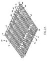
- FIG. 1A Portions of an exemplary version of a radius belt 20 having features of the invention are shown negotiating a turn in FIG. 1A and a straight in FIG. 1B.
- the endless belt is composed of a succession of belt rows, preferably made of injection-molded plastic, connected end to end by pivot rods, or hinge pins 22.
- the first row comprises a first set 26 of hinge elements along a first end 28 of the row and a second set 27 of hinge elements along an opposite second end 29 of the row.
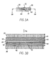
- An elongated slot 30 is formed in each of the first and second hinge elements of the first row.
- the slots at each end are axially aligned across the width of the belt and are elongated in the direction of belt travel.
- the first and second sets of hinge elements extend from a central portion 32 forming a transverse connecting member across the width of the row.
- the second row 25 comprises a first set 34 of hinge elements along a first end 36 and a second set 35 of hinge elements along a second end 37.
- a fan-shaped aperture 38 is formed in each of the first and second hinge elements 34, 35 in axial alignment along each end of the row.
- the fan shape is characterized in a preferred version by a rounded vertex 40 at the distal ends of the hinge elements fanning or flaring out along an approximately 60° sector along a radius 41 at the proximal ends of the hinge elements.
- the hinge elements extend from a central portion 42 forming a transverse connecting member similar to that of the first row.
- the second set of hinge elements of a first row are interleaved with the first set of hinge elements of an adjacent second row, whose second set of hinge elements are interleaved with the first set of hinge elements of another first row and interconnected by hinge pins 22 inserted in the aligned slots 30 and apertures 38 between rows to form a belt 20.
- Each row can be constructed of a single integral belt module molded to width or individual side-by-side modules including one or more hinge elements at each end in a bricklaid or a continuous-seam configuration.
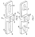
- each row comprises a stack of individual links 48, 49, better shown in FIGS. 6 and 7.
- each link 48 on the first row 24 includes a first hinge element 26 and a second hinge element 27 extending from a central portion 32 acting as a spacer to provide a gap 50 (as shown in FIG. 1A) between hinge elements along each end of the row.
- the central portion 32 includes a bore 44 to admit a support element 45, such as a threaded rod or a bolt, on which a plurality of links 48 can be stacked side by side to form the row.
- a boss 86 extends from the central portion to mate with a boss receptacle (not shown) on the other side of the link.
- Fastener hardware 52 such as washers, nuts, and bolt heads, are used to retain the stacked links into a sturdy belt row.
- the links 49 of the second row 25 are similarly formed and joined to construct the second row, as shown in FIG. 7.
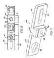
- a first nut-capturing edge link 54 (shown in FIGS. 1B and 9) is used at the edge 47 of the second row 25.
- the edge link includes a hexagonal recess 56 for a nut that threads onto an end of the support element 45.
- the fan-shaped apertures 38 are also recessed into the first edge piece 54 to prevent the end of the hinge pin from protruding beyond the belt edge.
- a second nut-capturing edge link 55 contains a similar recess 56' for the edge of the first belt row 24.
- the opposite second edge 46 of the belt is terminated in edge links 58, 59 including recesses 60, 60' for bolt heads.
- the first row is terminated in an edge link 58 with a round recess 60 for the head of a bolt used as the support element.
- the first row edge link also recesses the slots 30 to prevent the end of the hinge pin from projecting beyond the edge of the belt.
- the second row terminates in an edge link 59 that has a similar recess 60' for a bolt head.
- top surfaces 62 of the hinge elements 26, 27, 34, 35 and the top surfaces 63 of the central portions 32, 42 form a top article-conveying belt surface 64, which is generally planar for product stability.
- the top surfaces 63 of the central portions could alternatively be recessed.
- the bottom side of the belt can include a number of features. The features can be integrally molded as part of each row or can be, as shown in FIGS. 2A and 2B, part of an individual special-purpose link.
- FIG. 2A shows a special holddown link 66 in the first row 24 of the belt.
- the hinge elements 26, 27 extend downward from the bottom side 65 of the belt a distance and terminate in a horizontal flange 68 with sloped leading and trailing ends 69.
- the flange engages a wearstrip 70 (FIG. 8) at the outside of a turn to hold the belt down so that it does not flip up.
- the holddown link also includes a tooth 72 projecting outward from the extended hinge elements on the bottom side of the belt. The teeth project toward the outer side edge of the belt for engaging a mating drive belt or sprocket (not shown) or a trolley gear as might be used in a first-in, first-out article accumulating system.
- Another tooth link 74, without holddown flanges, includes only the tooth 72.
- Left- and right-hand links performing similar functions make up the set of links needed for complete versatility in constructing a custom belt.
- the belt can be driven from the side by engagement with the teeth 72 or by an intermediate caterpillar-type drive engaging lugs 76 extending from the bottom surface 65 of the belt.
- the lugs can be formed in individual links 78 in the form of a box and grouped together as shown in FIGS. 2A and 2B to provide extra drive area.
- the lugs provide a drive surface 80 engaged by the driving surfaces, such as cogs or roller wheels, of an intermediate drive belt or chain. As shown in the drawing, the drive surfaces are parallel to the width of the belt, but could also be at an angle 82 to facilitate engagement of the lug drive surface by a driving surface, especially where belt pitch may be varying because of changes in temperature, wear, loading, and manufacturing variations.
- the lugs shown also include aligned holes 84 to accept a press-fit pin 85 to fortify the side by side lugs. (Such a pin would be unnecessary in an integrally molded belt.)
- the preferred version of the hinge pin 22 has a tapered oblong shape.
- the pin extends from a wider first pin end 88 to a narrower second pin end 89.
- the pin preferably has a constant height along its length.
- the pin extends in the direction of belt travel from a front surface 90 to a rear surface 91.
- the front 90 is straight along the length of the hinge pin.
- the rear is straight across a first region 92 to give a constant cross section throughout the first region, which extends from the first end 88 of the pin toward the second end 89.
- the rounded front and rear surfaces give the pin a generally oval cross section.
- the rear of a second region 93 which extends from the second end of the pin toward the first end, is tapered toward the second end so that the long axis l of the cross section, i.e., the distance between the front 90 and rear 91 of the pin increases with distance from the second end to a maximum l 2 less than or equal to the long axis l 1 , of the cross section of the first region 92.
- the long axis l 2 of the second region varies linearly with distance from the second end.
- the front 90 of the hinge pin is pulled tightly against the mating vertices 40 of the fan-shaped apertures by belt tension.
- the rear 91 of the second region 93 of the hinge pin is pulled tightly against the distal ends 98 of the slots 30 encompassing the second region.
- the tapered second region defines the changing pitch of the belt across its width as it fans out at its outer edges in a turn.
- the pitch of the belt decreases from the outside of the turn inwardly as defined by the long axis l 2 of the cross section of the second region.
- the rear of the first region 92 is spaced from the distal ends of the slots in the hinge elements encompassing the first region of the hinge pin owing to the collapse of the rows into each other at the inside of the turn.
- the hinge elements encompassing the second region of the pin share the belt tension in a turn.
- an intermediate third region 94 forms a transition from the first 92 to the second 93 region.
- the long axis l 3 of the cross section of the third region varies from the maximum long axis l 2 of the cross section of the second region to the constant long axis l 1 of the cross section of the first region.
- the variation in l 3 can be linear or follow any other monotonic relationship that allows the tensile load to be transferred smoothly from the inner links to the outer links through the interior links as the belt enters a turn and vice versa as it exits a turn.
- the tapered oblong hinge pin allows for a strong belt without the need for oversizing it for radius applications.
- it is preferably manufactured by injection molding, but could alternatively be machined.
- the belt In order for the belt to articulate about a drive sprocket or to enter or exit an inclined conveying path, the belt must be able to pivot at the hinge between consecutive rows.
- the shape of the hinge pin 22 residing in the slots 30 does not allow the pin to rotate relative to the slots.
- the fan-shaped apertures 38 in the hinge elements interleaved with the slotted hinge elements include a wider sectorial portion along a proximal surface 41, which could be a radial surface
- the length of the radius from the vertex 40, in which the front of the hinge pin 22 is nested, is just slightly greater than the long axis 11 of the first region 92 of the hinge pin.
- the sectorial portion allows the hinge pin and the interleaved slotted link row to pivot about the row with fan-shaped apertures both up and down according to the vertex angle of the aperture.
- the fan-shaped apertures allow forward- and back-flexing of a belt using an oblong hinge pin.
- the fan-shaped aperture could alternatively have a more triangular shape, in which case the proximal surface 41 would be straight instead of curved.
- the sectorial portion need not be symmetric about the hinge pin's position on level runs. If the belt is not required to backflex, for example, the sectorial portion needs to extend only downwardly from a horizontal plane containing the vertex to allow the belt to articulate about a sprocket.
- the version of the hinge pin 22 shown in FIGS. 5A-5C includes end tabs 100 and 101.
- the first end tab 100 extends outward from the rear 91 of the pin at the first end 88, and, as shown in FIG. 9, engages the link wall 102, such as on a nut-retaining edge link 54 to prevent the pin from entering the aligned openings further.
- the second end tab 101 extends outward from the front 90 of the pin at the second end 89. To insert the pin between two belt rows, the rows are first collapsed and the second, narrower end of the pin inserted with the front 90 of the pin sliding along the vertices 40 of the fan-shaped apertures 38 until the pin is fully inserted.
- the second end tab 101 is deflected as it slides through the aligned opening until it snaps into its original position in the gaps 50 between hinge elements.
- the second end tab 101 is retained by wall structure proximate the vertex 40 of a fan-shaped aperture near the second edge of the belt. In this way, the tabs prevent the hinge pin from working out of the belt during operation.
- many pin retention schemes are known in the art.
- the hinge pins could be tabless, and integral belt structure or other insertable occlusions could be used to retain a hinge pin providing the load-sharing advantages of the invention.
- the hinge elements 26, 27 of a row can be arranged along a radius approximating the turning radius of the belt rather than along straight lines perpendicular to the transverse connecting member. This provides extra strength in a turn and allows the belt to negotiate tighter turns.
- the gaps 50 between consecutive hinge elements are spaced wide enough to accommodate the interleaved radially aligned hinge elements of the adjacent row on straight runs.
- the hybrid link 104 includes a pair of hinge elements 106, 107 extending from a central portion 108 similar to the links of FIGS. 6 and 7.
- the central portion includes a bore 44 through the center of the central portion and a boss 86 for engaging with a boss receptacle on the opposite side of a similar link.
- the link 104 has a slot 30 in a first hinge element 106 and a reversed fan-shaped aperture in a second hinge element 107.
- Links such as these can be stacked on a support element through the bore to form a row of links that can be mated with a similar row of links to form an endless belt that accommodates the tapered oblong hinge pin 22 and provides performance on straight and curved conveyor belts similar to that of the belt of Fig. 1A.
- the hinge elements could also be staggered , or offset, from one another, rather than in-line as shown. Furthermore, the hinge elements could attach to the central portion at positions other than along one end and still provide the advantages of the invention.
- FIGS. 13 - 15 and 20 An integrally molded belt module generally replicating a stacked set of the links 104 is shown in FIGS. 13 - 15 and 20.
- the module 120 of FIG. 13 includes a transverse connecting member 122, shown in the form of an I-beam, from which a first set of hinge elements 124 extends to a first end 125 of the module and from which a second set of hinge elements 126 extends to a second end 127.
- both sets of hinge elements include aligned elongated slots 128 to accommodate a tapered hinge pin.
- the other module 121 shown in FIG. 13 is generally similar to the module 120 of FIG. 13.
- hinge elements 130, 132 of the module 121 include aligned fan-shaped apertures 134 to allow a belt made of alternating rows of modules 120 and modules 121 to flex about the hinge formed between consecutive rows.
- each module could alternatively have slots through one set of hinge elements and fan-shaped apertures through the opposite set.
- a set of hinge elements on one row having slots interdigitate into a set of hinge elements having fan-shaped apertures on an adjacent row.
- the modules of FIG. 13 have other features useful in conveyor applications.
- 126 is an integrally molded vertical extension 136 terminating in a horizontal flange 138 forming a holddown tab to engage a wearstrip 70 (FIG. 8) in the outside of a turn to hold the belt down.
- the vertical extension includes an accessory mounting tab 140 extending horizontally from the outer side of the vertical extension.
- the mounting tab includes retention structure 142 in the form of a raised trapezoidal element 144 between the top of the mounting tab and the transverse connecting member 122.
- the accessory mounting tab allows various accessories to be snapped onto the belt module and easily replaced as they wear.
- a vertical extension 146 without a horizontal flange is shown near a side edge of a module 121 in FIG. 15. The extension does not extend longitudinally as far as the holddown extension 136. It does include a similar accessory mounting tab 148.
- the side guard 150 includes a vertical plate 152 extending from a stem 154. At the bottom of the stem, a pair of retention tabs 156, each with a receptacle 157, extend horizontally to mate with the mounting tab 148 at the side edge of the belt. Once snapped in place, the side guard prevents conveyed products from falling off the side of a belt constructed of modules so equipped. Stubs extending from snap-in structure 158 at the side edge of the belt snap into engagement with undercut surfaces recessed in openings 159 in the side guard to help retain it in place.
- FIG. 16 Another accessory that can snap onto the accessory mounting tabs 140, 148 is a tooth 160 as shown in FIG. 16.
- the tooth shown is spade-shaped and has a built-in receptacle 162 for receiving the trapezoidal element 144 of the mounting tab.
- the tooth can be used as a drive surface that can be driven by a horizontal drive sprocket wheel, it can also be used to engage and drive a spider wheel gear 164, as shown in FIG. 17, geared between two strands 166, 167 of conveyor belting made of the modules of FIGS. 13 - 15. (The spider wheel could, of course, be used with the belts made of stacked links 104.)
- the spider wheel includes gear teeth 168 that mesh with the teeth 160 of the belts. In the application shown in FIG.
- the spider wheel is used in a product accumulation system. If the input strand 166 is running faster than the output strand 167, the spider wheel rotates and moves in the direction of arrow 170 to allow product to accumulate on longer stretches of belt.
- the spider wheel includes a scraper assembly (not shown) to divert product from the input strand across the spider wheel to the output strand. When the output strand moves faster, the spider wheel moves in the direction opposite arrow 170 to shorten the accumulation zone. When both strands move at the same speed, the spider wheel merely rotates in place.
- the lug includes a vertical drive surface 174 supported by struts 175 (in FIG. 13) joined by a plate 178.
- the lug could equivalently be solid, but generally does not require so much extra material because the struts and plate give it enough strength without more mass than necessary.
- the drive surface could be parallel to the transverse connecting member 122, it is preferably oriented obliquely to the connecting member at an angle A.
- the drive surface could be angled off vertical.
- the drive surface could be sloped from the bottom of the modules rearwardly to provide means for engaging cogs to hold the belt down.
- a belt made of the modules or links of the invention can be driven by cogs engaging the drive surfaces, by the threads of a worm gear, or, as shown in FIG. 18 and schematically represented in FIG. 19, by rollers 180 of a roller chain 182.
- the roller chain forms an intermediate drive that is driven by a motor (not shown) rotating a horizontal drive sprocket 184.
- An idler sprocket 186 loops the chain back to the drive sprocket.
- one drive surface typically carries all the load without sharing it among other drive surfaces. This results in earlier belt failure.
- variations in belt pitch are accommodated by the angled orientation of the drive surfaces, which allows each roller 180 to ride along the drive surface to a point at which each roller is driving the belt.
- the drive chain 182 comes away from the drive sprocket 184 or enters the idler sprocket 186, its angle of attack is much steeper to allow for an unobstructed entry into and exit from driving engagement with the drive surfaces.
- a linear 190 drive path for the chain in the drive region is effective and simple to construct
- a curved chain drive path 192 as seen in phantom in FIG. 19, bowed slightly outwardly from the linear path, could provide even better performance.
- FIG. 20 A bottom view of three rows of a slightly different version of a belt constructed of integrally molded modules is shown in FIG. 20. Besides showing the oblique angle A of the drive surfaces 174 of the drive lugs 172, FIG. 20 shows a feature that allows for easy replacement of modules while the belt is still in the conveyor frame.
- a first belt row 194 has a single holddown tab 196 at the left side of FIG. 20.
- a successive second belt row 195 has a single holddown tab 197 at the right side.
- the rows 194, 195 could also include accessory mounting tabs 140, 148 (as in FIGS. 14 and 15) for attaching, for example, a tooth, such as the tooth 160 in FIG. 16.
- Each row could also include a raised T-shaped accessory support 198 to hold a tooth attached to the accessory mounting tab in position.
- Complementary receiving structure 199 on an accessory tooth is engaged by the accessory support 198, which inhibits the tooth from pivoting out of position as it engages a mating gear wheel.
- the hinge pin 110 is generally a dual-sided version of the pin 22 of FIGS. 5A-5B. Inserted into the aligned openings of a conveyor belt as in FIG. 1A, the bilateral hinge pin allows the belt to turn a radius to the left or to the right with the tensile load shared among the hinge elements at the outside of the turn on curved conveyor paths and by the middle hinge element on a straight run.
- the belt can be made of materials other than injection-molded thermoplastics ⁇ metals, ceramics, and machined plastics being other examples.
- the hinge pin could be metal, plastic, fiberglass, or other material, and could be molded, cast, or machined.
- each row could be constructed of a set of stacked links or could be integrally formed with the central bore and support element eliminated.
Landscapes
- Engineering & Computer Science (AREA)
- Mechanical Engineering (AREA)
- Chain Conveyers (AREA)
- Dowels (AREA)
- Cable Accessories (AREA)
- Supports For Pipes And Cables (AREA)
- Emergency Lowering Means (AREA)
- Buckles (AREA)
Abstract
Description
Claims (10)
- A modular conveyor belt (20) suitable for conveying items in a direction of travel that may include a curved path, comprising:characterised by each hinge pin having an oblong cross section in the direction of belt travel, the oblong cross section of the tapered region increasing in length with distance inwardly from the side of the belt (20).a plurality of successive rows (24,25) of one or more belt modules (104;120;121) including a set (26,27) of hinge elements (34,35;130,132;124,126) at each end of each row interleaved with a set of hinge elements of an adjacent row, the interleaved sets of hinge elements between each row having aligned openings (30,38) therethrough forming a transverse passageway; anda hinge pin (22;110) disposed in the passageway between each row having a tapered region (93) at a side of the belt (20) to form an endless conveyor belt having a hinge between successive rows, the oblong cross section of the tapered region increasing in length with distance inwardly from the side of the belt (20).
- A modular conveyor belt (20) as claimed in claim 1, wherein one of the interleaved sets of hinge elements (34,35;130,132;124,126) at each hinge forms aligned apertures (38;134) extending from a vertex (40) at the distal end of the hinge elements flaring out to a proximal surface (41) at the proximal ends of the hinge pins (22;110) to allow the belt (20) to articulate about the hinge pin.
- A modular conveyor belt (20) as claimed in claim 2, wherein the other of the sets of interleaved hinge elements at each hinge circumscribes aligned slots (30;128) to accommodate the oblong hinge pin (22;110).
- A modular conveyor belt (20) as claimed in claim 1, 2 or 3, wherein the hinge pin (22; 110) further includes a straight region (92) whose oblong cross section is constant.
- A modular conveyor belt (20) as claimed in claim 4, wherein the hinge pin (22;110) further includes an intermediate region between the tapered region and the straight region (94), the cross section of the intermediate region varying monotonically from the straight region to the tapered region.
- A modular conveyor belt (20) as claimed in one of claims 1 to 5, wherein the long axis (l2) of the cross section of the tapered region in the direction of belt travel increases linearly with distance from the side edge of the belt (20).
- A modular conveyor belt (20) as claimed in any one of claims 1 to 6, wherein the hinge pin includes a leading front surface (90) and a trailing rear surface (91) in the direction of belt travel and wherein the front surface is straight along the length of the hinge pin (22;110) and the rear surface is parallel to the front surface along a first region and wherein the rear surface tapers towards the front surface with distance toward an end of the hinge pin in the tapered region.
- A modular conveyor belt (20) as claimed in any one of claims 1 to 7, further comprising an extension (136;146) extending from an underside of a belt row, the extension (136;146) including an accessory mounting tab (140;148) for attaching one of a variety of accessories (150;160) to the belt.
- A modular conveyor belt (20) as claimed in any one of claims 1 to 8, further comprising a drive lug (172) extending downwardly from an underside of a belt row, the drive lug (172) including a drive surface (174).
- A modular conveyor belt (20) as in claim 9, wherein the drive surface (174) is oriented oblique to the transverse direction.
Applications Claiming Priority (5)
| Application Number | Priority Date | Filing Date | Title |
|---|---|---|---|
| US8942098P | 1998-06-16 | 1998-06-16 | |
| US89420P | 1998-06-16 | ||
| US10717198P | 1998-11-05 | 1998-11-05 | |
| US107171P | 1998-11-05 | ||
| PCT/US1999/013435 WO1999065801A1 (en) | 1998-06-16 | 1999-06-15 | Modular belt with tapered oblong hinge pins |
Publications (3)
| Publication Number | Publication Date |
|---|---|
| EP1154941A4 EP1154941A4 (en) | 2001-11-21 |
| EP1154941A1 EP1154941A1 (en) | 2001-11-21 |
| EP1154941B1 true EP1154941B1 (en) | 2003-10-08 |
Family
ID=26780570
Family Applications (1)
| Application Number | Title | Priority Date | Filing Date |
|---|---|---|---|
| EP99927532A Expired - Lifetime EP1154941B1 (en) | 1998-06-16 | 1999-06-15 | Modular belt with tapered oblong hinge pins |
Country Status (7)
| Country | Link |
|---|---|
| US (1) | US6474464B1 (en) |
| EP (1) | EP1154941B1 (en) |
| JP (1) | JP4378054B2 (en) |
| AT (1) | ATE251582T1 (en) |
| AU (1) | AU4441299A (en) |
| DE (1) | DE69912004T2 (en) |
| WO (1) | WO1999065801A1 (en) |
Families Citing this family (33)
| Publication number | Priority date | Publication date | Assignee | Title |
|---|---|---|---|---|
| US6696003B2 (en) * | 2001-05-29 | 2004-02-24 | Habasit Ag | Methods for manufacturing a module for a modular conveyor belt having a sandwich layer construction |
| DE20109161U1 (en) * | 2001-06-02 | 2002-07-11 | Schuster Thomas | Link belt, especially for round balers |
| US6604625B2 (en) | 2001-10-31 | 2003-08-12 | The Laitram Corporation | Operating modular conveyor belts with migrating hinge pins |
| US7246699B2 (en) * | 2002-03-08 | 2007-07-24 | Frost Links, Inc. | Conveyor chain |
| FR2841882B1 (en) * | 2002-07-05 | 2004-10-01 | Gebo Ind | CONVEYOR MAT |
| WO2004058603A1 (en) * | 2002-12-24 | 2004-07-15 | Krones Ag | Modular conveyor belt |
| US6837367B1 (en) | 2003-11-05 | 2005-01-04 | Laitram, L.L.C. | Modular plastic conveyor belt with high beam strength |
| US7036658B2 (en) * | 2003-11-13 | 2006-05-02 | Hartness International, Inc. | Gripper conveyor with clear conveying path and related conveyor link |
| US7021453B2 (en) | 2003-11-13 | 2006-04-04 | Hartness International, Inc. | Conveyor with gear mechanism gripper and related conveyor link |
| US6997308B2 (en) * | 2004-07-12 | 2006-02-14 | Laitram, L.L.C. | Welded conveyor belt modules, belts made of welded modules, and method of making welded modules |
| US7080729B2 (en) * | 2004-08-25 | 2006-07-25 | Habasit Ag | Belt module with oblong pivot hole |
| CN101132844B (en) * | 2005-02-24 | 2010-09-08 | 莱特拉姆有限责任公司 | Modular screen belt |
| US7950072B1 (en) | 2005-06-03 | 2011-05-31 | Violet Hanson | Reversible belt with slide buckle |
| ES2265293B1 (en) * | 2005-07-28 | 2008-02-16 | Thyssenkrupp Norte, S.A. | MOBILE HALL. |
| US7530454B2 (en) * | 2005-11-08 | 2009-05-12 | Ashworth Bros. Inc. | Conveyor belt |
| EP1954602A2 (en) * | 2005-11-23 | 2008-08-13 | Frost Links, Inc. | Pin assembly for conveyor chain |
| JP2009527429A (en) * | 2006-02-16 | 2009-07-30 | フロスト・リンクス・インコーポレイテッド | Conveyor chain pin element with reservoir |
| US8657100B2 (en) | 2006-02-16 | 2014-02-25 | Frost Links, Inc. | Conveyor slide plate with reservoir |
| US7438179B2 (en) * | 2006-08-30 | 2008-10-21 | Laitram, L.L.C. | Abrasion-resistant hinge rods in modular plastic conveyor belts |
| US8028823B2 (en) * | 2007-02-23 | 2011-10-04 | Laitram, L.L.C. | Stacked attachments for modular conveyor belts |
| US7360643B1 (en) * | 2007-03-20 | 2008-04-22 | Habasit Ag | Electroconductive modular belt |
| US7837028B2 (en) * | 2008-04-24 | 2010-11-23 | Habasit Ag | Radius chain modular conveyor |
| GB2459740B (en) * | 2008-05-07 | 2012-03-14 | Pennine Ind Equipment Ltd | Enclosure member |
| NL2007860C2 (en) | 2011-11-24 | 2013-05-27 | Rexnord Flattop Europe Bv | MODULAR TRANSPORT MAT AND TRANSPORTER WITH A MODULAR TRANSPORT MAT. |
| WO2014066556A1 (en) | 2012-10-25 | 2014-05-01 | Solus Industrial Innovations, Llc | Device and method for controlling the wear of the rail of a conveyor |
| MX2015006770A (en) | 2012-11-29 | 2015-10-29 | Solus Ind Innovations Llc | Side-flexing conveyors. |
| US8905228B2 (en) * | 2013-02-04 | 2014-12-09 | Laitram, L.L.C. | Self-supporting conveyor belt |
| PL3148917T3 (en) * | 2014-05-28 | 2018-09-28 | Inventio Ag | Fixing device for fixing a pallet to a means of traction |
| CN107207161B (en) * | 2015-02-05 | 2019-12-24 | 莱特拉姆有限责任公司 | Conveyor belt module with stepped hinge channel |
| DE102015011483B4 (en) | 2015-09-08 | 2017-04-13 | Lipsia Automation GmbH | Drive for conveyor systems |
| EP3235743A1 (en) | 2016-04-19 | 2017-10-25 | MULTIVAC Sepp Haggenmüller SE & Co. KG | Transport unit with vacuum device and method for transporting of shells |
| US10183809B2 (en) * | 2016-05-24 | 2019-01-22 | Habasit Ag | Pin retention for conveyor modules |
| CN110723463A (en) * | 2019-09-27 | 2020-01-24 | 深圳市华南新海传动机械有限公司 | Combined module of transmission band |
Family Cites Families (10)
| Publication number | Priority date | Publication date | Assignee | Title |
|---|---|---|---|---|
| US4140025A (en) | 1976-07-19 | 1979-02-20 | The Laitram Corporation | Link chain having non-frictional couplings |
| US4138011A (en) * | 1976-04-28 | 1979-02-06 | The Laitram Corporation | Non-pivotal modular conveyor belt and modular links therefor |
| US4925016A (en) * | 1987-10-06 | 1990-05-15 | The Laitram Corporation | Heavy duty modular conveyor belt and sprocket with unique tracking |
| US5125874A (en) | 1991-01-22 | 1992-06-30 | The Laitram Corporation | Long life modular link belts suitable for abrasive environments |
| US5346059A (en) | 1991-02-19 | 1994-09-13 | Guy Irwin | Conveyor belt module |
| US5174439A (en) | 1991-07-03 | 1992-12-29 | Cambridge Wire Cloth Company | Modular plastic turn belt conveyor system, module, belt and drive therefor |
| US5318169A (en) * | 1993-05-27 | 1994-06-07 | William G. Faulkner | Spiral conveyor belt |
| US5431275A (en) | 1993-05-27 | 1995-07-11 | William G. Faulkner | Conveyor belt with rotatable tapered link shift |
| US5439751A (en) * | 1993-12-30 | 1995-08-08 | Carondelet Foundry Company | Ore pellet cooler side plate |
| FI101098B (en) * | 1996-05-03 | 1998-04-15 | Finnketju Invest Oy | Method of chain use and chain |
-
1999
- 1999-06-15 AU AU44412/99A patent/AU4441299A/en not_active Abandoned
- 1999-06-15 DE DE69912004T patent/DE69912004T2/en not_active Expired - Lifetime
- 1999-06-15 AT AT99927532T patent/ATE251582T1/en not_active IP Right Cessation
- 1999-06-15 US US09/701,127 patent/US6474464B1/en not_active Expired - Lifetime
- 1999-06-15 WO PCT/US1999/013435 patent/WO1999065801A1/en active IP Right Grant
- 1999-06-15 JP JP2000554637A patent/JP4378054B2/en not_active Expired - Fee Related
- 1999-06-15 EP EP99927532A patent/EP1154941B1/en not_active Expired - Lifetime
Also Published As
| Publication number | Publication date |
|---|---|
| JP4378054B2 (en) | 2009-12-02 |
| AU4441299A (en) | 2000-01-05 |
| WO1999065801A1 (en) | 1999-12-23 |
| JP2002518270A (en) | 2002-06-25 |
| US6474464B1 (en) | 2002-11-05 |
| EP1154941A4 (en) | 2001-11-21 |
| DE69912004D1 (en) | 2003-11-13 |
| DE69912004T2 (en) | 2004-08-26 |
| EP1154941A1 (en) | 2001-11-21 |
| ATE251582T1 (en) | 2003-10-15 |
Similar Documents
| Publication | Publication Date | Title |
|---|---|---|
| EP1154941B1 (en) | Modular belt with tapered oblong hinge pins | |
| US5921379A (en) | Modular conveyor belt suitable for following straight or curved paths | |
| CA2380127C (en) | Snap-on side guards | |
| CA2477145C (en) | Rodless conveyor belt or chain | |
| EP0477205B1 (en) | Flat top conveyor | |
| US7661524B2 (en) | Side-flexing conveyor belt | |
| US5775480A (en) | Low-friction conveyor assembly | |
| US5372248A (en) | Radius conveyor belt | |
| US4909380A (en) | Low backline pressure chain | |
| US5330045A (en) | Low backline pressure chain | |
| EP1980504B1 (en) | Modular plastic conveyor belt with high beam strength | |
| US20130213775A1 (en) | Abrasion resistant conveyor belt | |
| JP2002518270A5 (en) | ||
| KR20080004542A (en) | Variable angled-roller belt and conveyor | |
| EP0380201B1 (en) | Conveyor belt module | |
| US6644466B2 (en) | Platform-top radius belt and modules | |
| EP1184305B1 (en) | Modular plastic conveyor belt | |
| US4858751A (en) | Wide chain conveyor assembly | |
| US7559421B1 (en) | Modular link conveyor chain with return run support arrangement | |
| EP0066530B1 (en) | Platform conveyor element for low backline pressure platform-chain conveyor | |
| WO2004054900A2 (en) | Flexible conveyor belt with easily replaceable and adjustable flight and lane dividers | |
| EP1911694A1 (en) | Rodless conveyor belt or chain |
Legal Events
| Date | Code | Title | Description |
|---|---|---|---|
| PUAI | Public reference made under article 153(3) epc to a published international application that has entered the european phase |
Free format text: ORIGINAL CODE: 0009012 |
|
| 17P | Request for examination filed |
Effective date: 20001106 |
|
| A4 | Supplementary search report drawn up and despatched |
Effective date: 20010806 |
|
| AK | Designated contracting states |
Kind code of ref document: A4 Designated state(s): AT BE CH CY DE DK ES FI FR GB GR IE IT LI LU MC NL PT SE Kind code of ref document: A1 Designated state(s): AT BE CH CY DE DK ES FI FR GB GR IE IT LI LU MC NL PT SE |
|
| 17Q | First examination report despatched |
Effective date: 20020809 |
|
| GRAH | Despatch of communication of intention to grant a patent |
Free format text: ORIGINAL CODE: EPIDOS IGRA |
|
| GRAH | Despatch of communication of intention to grant a patent |
Free format text: ORIGINAL CODE: EPIDOS IGRA |
|
| RAP1 | Party data changed (applicant data changed or rights of an application transferred) |
Owner name: HARTNESS INTERNATIONAL, INC. Owner name: LAITRAM L.L.C. |
|
| GRAA | (expected) grant |
Free format text: ORIGINAL CODE: 0009210 |
|
| AK | Designated contracting states |
Kind code of ref document: B1 Designated state(s): AT BE CH CY DE DK ES FI FR GB GR IE IT LI LU MC NL PT SE |
|
| PG25 | Lapsed in a contracting state [announced via postgrant information from national office to epo] |
Ref country code: NL Free format text: LAPSE BECAUSE OF FAILURE TO SUBMIT A TRANSLATION OF THE DESCRIPTION OR TO PAY THE FEE WITHIN THE PRESCRIBED TIME-LIMIT Effective date: 20031008 Ref country code: FI Free format text: LAPSE BECAUSE OF FAILURE TO SUBMIT A TRANSLATION OF THE DESCRIPTION OR TO PAY THE FEE WITHIN THE PRESCRIBED TIME-LIMIT Effective date: 20031008 Ref country code: CY Free format text: LAPSE BECAUSE OF FAILURE TO SUBMIT A TRANSLATION OF THE DESCRIPTION OR TO PAY THE FEE WITHIN THE PRESCRIBED TIME-LIMIT Effective date: 20031008 Ref country code: BE Free format text: LAPSE BECAUSE OF FAILURE TO SUBMIT A TRANSLATION OF THE DESCRIPTION OR TO PAY THE FEE WITHIN THE PRESCRIBED TIME-LIMIT Effective date: 20031008 Ref country code: AT Free format text: LAPSE BECAUSE OF FAILURE TO SUBMIT A TRANSLATION OF THE DESCRIPTION OR TO PAY THE FEE WITHIN THE PRESCRIBED TIME-LIMIT Effective date: 20031008 |
|
| REG | Reference to a national code |
Ref country code: GB Ref legal event code: FG4D |
|
| REG | Reference to a national code |
Ref country code: CH Ref legal event code: EP |
|
| REG | Reference to a national code |
Ref country code: IE Ref legal event code: FG4D |
|
| REF | Corresponds to: |
Ref document number: 69912004 Country of ref document: DE Date of ref document: 20031113 Kind code of ref document: P |
|
| REG | Reference to a national code |
Ref country code: CH Ref legal event code: NV Representative=s name: GEORG FISCHER AG |
|
| PG25 | Lapsed in a contracting state [announced via postgrant information from national office to epo] |
Ref country code: SE Free format text: LAPSE BECAUSE OF FAILURE TO SUBMIT A TRANSLATION OF THE DESCRIPTION OR TO PAY THE FEE WITHIN THE PRESCRIBED TIME-LIMIT Effective date: 20040108 Ref country code: GR Free format text: LAPSE BECAUSE OF FAILURE TO SUBMIT A TRANSLATION OF THE DESCRIPTION OR TO PAY THE FEE WITHIN THE PRESCRIBED TIME-LIMIT Effective date: 20040108 Ref country code: DK Free format text: LAPSE BECAUSE OF FAILURE TO SUBMIT A TRANSLATION OF THE DESCRIPTION OR TO PAY THE FEE WITHIN THE PRESCRIBED TIME-LIMIT Effective date: 20040108 |
|
| PG25 | Lapsed in a contracting state [announced via postgrant information from national office to epo] |
Ref country code: ES Free format text: LAPSE BECAUSE OF FAILURE TO SUBMIT A TRANSLATION OF THE DESCRIPTION OR TO PAY THE FEE WITHIN THE PRESCRIBED TIME-LIMIT Effective date: 20040119 |
|
| NLV1 | Nl: lapsed or annulled due to failure to fulfill the requirements of art. 29p and 29m of the patents act | ||
| ET | Fr: translation filed | ||
| PG25 | Lapsed in a contracting state [announced via postgrant information from national office to epo] |
Ref country code: LU Free format text: LAPSE BECAUSE OF NON-PAYMENT OF DUE FEES Effective date: 20040615 Ref country code: IE Free format text: LAPSE BECAUSE OF NON-PAYMENT OF DUE FEES Effective date: 20040615 |
|
| PG25 | Lapsed in a contracting state [announced via postgrant information from national office to epo] |
Ref country code: MC Free format text: LAPSE BECAUSE OF NON-PAYMENT OF DUE FEES Effective date: 20040630 |
|
| PLBE | No opposition filed within time limit |
Free format text: ORIGINAL CODE: 0009261 |
|
| STAA | Information on the status of an ep patent application or granted ep patent |
Free format text: STATUS: NO OPPOSITION FILED WITHIN TIME LIMIT |
|
| 26N | No opposition filed |
Effective date: 20040709 |
|
| REG | Reference to a national code |
Ref country code: IE Ref legal event code: MM4A |
|
| PG25 | Lapsed in a contracting state [announced via postgrant information from national office to epo] |
Ref country code: PT Free format text: LAPSE BECAUSE OF NON-PAYMENT OF DUE FEES Effective date: 20040308 |
|
| REG | Reference to a national code |
Ref country code: CH Ref legal event code: NV Representative=s name: GACHNANG AG PATENTANWAELTE, CH |
|
| REG | Reference to a national code |
Ref country code: FR Ref legal event code: PLFP Year of fee payment: 18 |
|
| PGFP | Annual fee paid to national office [announced via postgrant information from national office to epo] |
Ref country code: GB Payment date: 20160525 Year of fee payment: 18 Ref country code: CH Payment date: 20160425 Year of fee payment: 18 |
|
| PGFP | Annual fee paid to national office [announced via postgrant information from national office to epo] |
Ref country code: FR Payment date: 20160531 Year of fee payment: 18 Ref country code: IT Payment date: 20160610 Year of fee payment: 18 |
|
| PGFP | Annual fee paid to national office [announced via postgrant information from national office to epo] |
Ref country code: DE Payment date: 20160629 Year of fee payment: 18 |
|
| REG | Reference to a national code |
Ref country code: DE Ref legal event code: R119 Ref document number: 69912004 Country of ref document: DE |
|
| REG | Reference to a national code |
Ref country code: CH Ref legal event code: PL |
|
| GBPC | Gb: european patent ceased through non-payment of renewal fee |
Effective date: 20170615 |
|
| REG | Reference to a national code |
Ref country code: FR Ref legal event code: ST Effective date: 20180228 |
|
| PG25 | Lapsed in a contracting state [announced via postgrant information from national office to epo] |
Ref country code: GB Free format text: LAPSE BECAUSE OF NON-PAYMENT OF DUE FEES Effective date: 20170615 Ref country code: CH Free format text: LAPSE BECAUSE OF NON-PAYMENT OF DUE FEES Effective date: 20170630 Ref country code: LI Free format text: LAPSE BECAUSE OF NON-PAYMENT OF DUE FEES Effective date: 20170630 Ref country code: DE Free format text: LAPSE BECAUSE OF NON-PAYMENT OF DUE FEES Effective date: 20180103 |
|
| PG25 | Lapsed in a contracting state [announced via postgrant information from national office to epo] |
Ref country code: IT Free format text: LAPSE BECAUSE OF NON-PAYMENT OF DUE FEES Effective date: 20170615 Ref country code: FR Free format text: LAPSE BECAUSE OF NON-PAYMENT OF DUE FEES Effective date: 20170630 |