EP1155346B1 - Retroreflective articles having polymer multilayer reflective coatings - Google Patents
Retroreflective articles having polymer multilayer reflective coatings Download PDFInfo
- Publication number
- EP1155346B1 EP1155346B1 EP99925887A EP99925887A EP1155346B1 EP 1155346 B1 EP1155346 B1 EP 1155346B1 EP 99925887 A EP99925887 A EP 99925887A EP 99925887 A EP99925887 A EP 99925887A EP 1155346 B1 EP1155346 B1 EP 1155346B1
- Authority
- EP
- European Patent Office
- Prior art keywords
- reflective coating
- layers
- optical elements
- retroreflective article
- polymer
- Prior art date
- Legal status (The legal status is an assumption and is not a legal conclusion. Google has not performed a legal analysis and makes no representation as to the accuracy of the status listed.)
- Expired - Lifetime
Links
Images

Classifications
-
- G—PHYSICS
- G02—OPTICS
- G02B—OPTICAL ELEMENTS, SYSTEMS OR APPARATUS
- G02B5/00—Optical elements other than lenses
- G02B5/12—Reflex reflectors
- G02B5/122—Reflex reflectors cube corner, trihedral or triple reflector type
- G02B5/124—Reflex reflectors cube corner, trihedral or triple reflector type plural reflecting elements forming part of a unitary plate or sheet
-
- G—PHYSICS
- G02—OPTICS
- G02B—OPTICAL ELEMENTS, SYSTEMS OR APPARATUS
- G02B5/00—Optical elements other than lenses
- G02B5/12—Reflex reflectors
- G02B5/126—Reflex reflectors including curved refracting surface
- G02B5/128—Reflex reflectors including curved refracting surface transparent spheres being embedded in matrix
-
- Y—GENERAL TAGGING OF NEW TECHNOLOGICAL DEVELOPMENTS; GENERAL TAGGING OF CROSS-SECTIONAL TECHNOLOGIES SPANNING OVER SEVERAL SECTIONS OF THE IPC; TECHNICAL SUBJECTS COVERED BY FORMER USPC CROSS-REFERENCE ART COLLECTIONS [XRACs] AND DIGESTS
- Y10—TECHNICAL SUBJECTS COVERED BY FORMER USPC
- Y10S—TECHNICAL SUBJECTS COVERED BY FORMER USPC CROSS-REFERENCE ART COLLECTIONS [XRACs] AND DIGESTS
- Y10S359/00—Optical: systems and elements
- Y10S359/90—Methods
Definitions
- the present invention pertains to retroreflective articles that have a multilayer reflective coating that includes multiple polymer layers disposed in optical association with a layer of optical elements.
- Retroreflective articles have the ability to redirect incident light back towards the light source. This unique ability has led to the wide-spread use of retroreflective articles on various substrates.
- retroreflective articles can be used on flat inflexible substrates, such as road signs and barricades; on irregular surfaces, such as corrugated metal truck trailers, license plates, and traffic barriers; and on flexible substrates, such as road worker safety vests, a jogger's shoes, roll up signs, and canvas-sided trucks.
- Beaded articles commonly use a multitude of glass or ceramic microspheres to retroreflect incident light.
- the microspheres are partially embedded in a support film, and a specular reflecting material is provided between the layer of microspheres and the support film.
- the reflecting material can be a metal layer (for example, an aluminum coating as disclosed in U.S. Pat. Nos. 3,700,478 and 4,648,932) or an inorganic dielectric mirror made up of multiple layers of inorganic materials that have different refractive indices (as disclosed in U.S. Pat. Nos. 3,700,305 and 4,763,985).
- Categories of beaded articles include exposed lens, enclosed lens, and encapsulated lens types.
- Exposed lens beaded articles have a layer of microspheres that are exposed to the environment.
- Enclosed lens beaded articles have a protective layer such as a transparent polymer resin contacting and surrounding the front side of the microspheres.
- Encapsulated lens articles have an air gap surrounding the front side of the microspheres and have a transparent film hermetically sealed to a support film to protect the microspheres from water, dirt, or other environmental elements.
- cube-corner sheeting typically employs a multitude of cube-corner elements to retroreflect incident light.
- the cube-corner elements project from the back surface of a body layer.
- incident light enters the sheet at a front surface, passes through the body layer to be internally reflected by the faces of the cube-corner elements, and subsequently exits the front surface to be returned towards the light source.
- Reflection at the cube-corner faces can occur by total internal reflection when the cube-corner elements are encased in a lower refractive index media (e.g., air) or by reflection off a specular reflective coating such as a vapor deposited aluminum film.
- a lower refractive index media e.g., air
- the present invention provides a new approach to supplying retroreflective articles with reflective coatings.
- the present invention provides a retroreflective article as defined by claim 1.
- Retroreflective articles of this invention differ from known retroreflective articles in that the optical elements have an associated reflective coating that comprises multiple polymer layers.
- the polymer layers can have indices of refraction and thicknesses selected such that the overall multilayer reflective coating reflects light in a desired wavelength range.
- Known retroreflective articles have used metal reflective layers, which in some instances can be subject to oxidation from air or moisture. When oxidized, the reflective layer can suffer a substantial loss in its reflective ability.
- Retroreflective articles have also employed multilayered inorganic dielectric mirrors that can be susceptible to air or moisture induced corrosion that can degrade reflectivity and/or lead to delamination of the layers.
- the polymer multilayer reflective coating of the present invention is beneficial in that it can be made highly reflective to light in a desired wavelength band(s), while also being capable of resisting undesirable environmental effects, such as air and/or moisture induced corrosion, to which known inorganic reflective coatings can be susceptible.
- the multilayer reflective coating of the present invention can also include inorganic and/or non-polymer layers disposed adjacent to or between the multiple polymer layers, for example, to help overcome limitations of known inorganic reflector coatings by rendering them more resistant to water, acids, bases, corrosion or other environmental degradation.
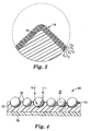
- FIG. 1 is a plan view schematic representation of a portion of the backside of a cube-corner retroreflective article 10 in accordance with the present invention.
- FIG. 2 is a cross-sectional representation of the cube-corner retroreflective article 10 shown in FIG. 1 taken along line 2 ⁇ 2.
- FIG. 3 is an enlarged inverted view of a portion of a cube-corner element 16 taken from region 3 of FIG. 2.
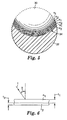
- FIG. 4 is a cross-sectional schematic of a portion of a beaded retroreflective article 40 in accordance with the present invention.
- FIG. 5 is an enlarged view of a portion of a microsphere element 30 taken from region 5 of FIG. 4.
- FIG. 6 is a schematic representation of adjacent layers in a multilayer reflective coating 34 useful in the present invention.
- FIG. 7 is a schematic representation of a coating method useful in the present invention.
- FIG. 1 shows a portion of a retroreflective article 10 that has a plurality of optical elements, which in this embodiment are shown as cube-comer elements 16, each defined by three faces 18 arranged to form a pyramidal shape.
- the cube-corner optical elements 16 are arranged as an ordered array and are shown to protrude out of the page of the drawing.
- the cube-corner elements 16 are disposed as matched pairs in an array on one side of the sheeting.
- Each cube-corner element 16 has the shape of a trihedral prism that has three exposed planar faces 18 .
- the planar faces 18 may be substantially perpendicular to one another (as in the corner of a room) with the apex 20 of the prism vertically aligned with the center of the base.
- the angle between the faces 18 typically is the same for each cube-corner element in the array and is about 90°.
- the angle can deviate from 90° as is well-known; see, for example, U.S. Pat. No. 4,775,219.
- the apex 20 of each cube-corner element 16 may be vertically aligned with the center of the base of the cube-corner element - see, for example, U.S. Pat. No. 3,684,348- the apex also may be canted to the center of the base as disclosed in U.S. Pat. No. 4,588,258.
- the present invention is not limited to any particular cube-corner geometry; however, of the many known cube-corner configurations (see, for example, U.S. Pat. Nos. 4,938,563; 4,775,219; 4,243,618; 4,202,600; and 3,712,706), the cube-corner sheeting described in U.S. Pat. No. 4,588,258 may be preferred because it provides wide angle retroreflection among multiple viewing planes.
- FIG. 2 shows a cross-sectional representation of the retroreflective article 10 taken along line 2 ⁇ 2 of FIG. 1.
- Retroreflective article 10 has a body portion 12 from which the cube-corner elements 16 protrude.
- the body portion 12 has a front side 13 through which incident light I enters.
- a reflective coating 14 is disposed on the article 10 in optical association with the cube-corner elements 16. Incident light I reflects off cube-corner faces 18 and becomes redirected in the general direction of the incident beam, as indicated by reflected light beam R.
- a reflective coating 14 may increase the efficiency of reflections off the cube-corner faces 18 in some instances.
- the body portion 12 and the optical elements 16 may be made from essentially any suitable light transmissible material.
- the body portion and cube-corner elements comprise light transmissible polymers. This means that the polymer will allow light, particularly actinic radiation or visible light, to pass therethrough.
- the polymer is able to transmit at least 70 percent of the intensity of the light incident upon it at a given wavelength. More preferably, the polymers that are used in the retroreflective sheeting of the invention have a light transmissibility of greater than 80 percent, and more preferably greater than 90 percent.
- FIG. 3 shows a magnified view of the portion of the cube-corner element indicated by circle 3 in FIG. 2.
- Reflective coating 14 includes multiple polymer layers.
- FIG. 3 shows a reflective coating 14 made up of six layers arranged as alternating layers of two different materials, at least one of which is a polymer, the materials having different refractive indices n 1 and n 2 .
- the reflective coating can include two or more layers, and any suitable combination of two or more polymer layers.
- the reflective coating has 2 to 200 layers, and more preferably 2 to 50 layers.
- each individual layer be thin relative to the cube-corner element heights (cube-comer heights measured from base to apex).
- the individual layers in the multilayer coating have thicknesses of less than about 10% of the cube-corner element height, more preferably less than about 5% of the cube-corner element height.
- the layers should have thicknesses that are appropriate for reflection of light in a desired wavelength range. The selection of layer thickness and refractive index of the materials in the multilayer reflective coating is discussed in more detail below.
- FIG. 4 illustrates a beaded retroreflective article 40 that includes optical elements in the form of microspheres 30 that are partially embedded in a binder layer 32.
- a reflective coating 34 is disposed between the layer of microspheres 30 and the binder layer 32.
- Optional substrate layer 36 can be used to add structural support.
- the beaded retroreflective article 40 as configured in FIG. 4 is typically referred to as an "exposed lens” beaded retroreflective article.
- An “exposed lens” sheeting is one where the optical elements, in this case microspheres, are exposed to the ambient environment, namely air.
- a protective layer (not shown) that covers or encapsulates the exposed portions of the microspheres can also be provided to make "enclosed lens” or "encapsulated lens” beaded retroreflective sheeting.
- exposed lens sheetings are described in the following U.S. Patents: 5,812,317; 4,763,985; and 3,700,478.
- encapsulated lens products are shown in U.S. Patent Nos. 5,784,198; 5,066,098; and 4,896,943. As shown in FIG.
- incident light I that enters a microsphere can be refracted toward the center of the microsphere, reflected off the reflective coating 34 behind the microsphere, and redirected out of the microsphere in the general direction of the incident light, as indicated by reflected light beam R .
- the microspheres used in a beaded product of the invention preferably are substantially spherical in shape to provide uniform and efficient retroreflection.
- the microspheres preferably also are highly transparent to minimize light absorption so that a large percentage of incident light is retroreflected.
- the microspheres often are substantially colorless but may be tinted or colored in some other fashion.
- the microspheres may be made from glass, a non-vitreous ceramic composition, or a synthetic resin. In general, glass and ceramic microspheres are preferred because they tend to be harder and more durable than microspheres made from synthetic resins. Examples of microspheres that may be useful in this invention are disclosed in the following U.S. Pat.
- the microspheres typically have an average diameter of about 10 to 500 ⁇ m, and preferably of about 20 to 250 ⁇ m. Microspheres smaller than these ranges tend to provide lower levels of retroreflection, and microspheres larger than these ranges may impart an undesirably rough texture to the retroreflective article or may undesirably reduce its flexibility when flexibility is a desired property. Microspheres used in the present invention typically have a refractive index of about 1.2 to 3.0, preferably about 1.6 to 2.7, and more preferably about 1.7 to 2.5.
- FIG. 5 shows a magnified view of a portion of the microsphere element 30 indicated by region 5 in FIG. 4.
- Reflective coating 34 has multiple polymer layers, which in this instance is made up of six layers arranged as alternating layers of two different materials, at least one of which is a polymer, the layers having different refractive indices n 1 and n 2 .
- the six alternating layers of two different materials as shown in FIG. 5 are merely illustrative.
- a multiple layer reflective coating that has two or more layers representing two or more different refractive indices can be used.
- the reflective coating preferably has 2 to 200 layers, and more preferably 2 to 50 layers.
- each layer be thin relative to the microsphere diameters.
- the individual layers in the multilayer coating have thicknesses of less than about 10% of the microsphere diameters, more preferably less than about 5% of the microsphere diameters.
- the individual polymer layers of the reflective coating typically have thicknesses that are less than 10% of the average size of the optical elements of the retroreflective article. Preferably, the individual polymer layers have thicknesses that are less than 5% the average size of the optical elements.
- the polymer layers preferably have thicknesses of less than 3 ⁇ m, more preferably less than 2 ⁇ m, and even more preferably less than 1 ⁇ m.
- each layer of the reflective coating is clear or essentially colorless to minimize light absorption and maximize light reflection, however, a great variety of visual effects may be achieved, if desired, when one or more of the layers are colored, such as with a dye.
- Such coloring agent if provided, preferably leaves the reflective coating substantially transparent.
- the individual layers of the multilayer reflective coating disposed on retroreflective articles according to the present invention preferably have thicknesses that are appropriate for reflection of light in a desired wavelength range.
- light having wavelengths within a desired wavelength range can be reflected when the combined optical thickness of two adjacent layers that have different indices of refraction is an odd multiple of one-half of a wavelength in the desired wavelength range.
- FIG. 6 indicates the relationship between layer thickness, index of refraction, and angle of incidence for an arbitrary incident light ray I .
- the combined optical thickness of the adjacent layers is simply n 1 t 1 +n 2 t 2 , where n is the index of refraction, t is the thickness, and the subscript denotes the layer.
- n is the index of refraction
- t is the thickness
- the subscript denotes the layer.
- a more general approximation of the combined optical thickness of adjacent layers can be given by ( n 1 t 1 +n 2 t 2 )/cos ⁇ . This approximation improves for small ⁇ , and is best for ⁇ less than about 20°.
- the difference in refractive index between adjacent layers can affect the reflectivity of the multilayer reflective coating.
- the larger the difference between n 1 and n 2 the stronger the reflection from the pair of layers.
- adjacent layers have indices of refraction that differ by at least 0.02, and more preferably by at least 0.05 or more, and still more preferably by at least 0.1 or more. Due to materials considerations, the difference in refractive index for adjacent polymer layers is typically less than about 1.2, and more typically less than 1, although higher refractive index differences might be achieved, and are contemplated for use in this invention, depending on the materials used.
- non-polymer materials such as certain metallic, inorganic, organometallic, and ceramic materials
- materials with a relatively high refractive index for visible light include PbO (index of 2.61), SiC (index of 2.68), TiO 2 (index of 2.71), and PbS (index of 3.91). These values can be compared with typical polymeric materials with refractive indices that range from about 1.3 to 1.7.
- refractive index differences of more than 1.2, or even more than 2 can be obtained in some instances when non-polymer layers are placed adjacent to polymer layers in the reflective coating.
- non-polymer inorganic and inorganic dielectric materials examples include: high index materials such as CdS, CeO 2 , CsI, GeAs, Ge, InAs, InP, InSb, ZrO 2 , Bi 2 O 3 , ZnSe, ZnS, WO 3 , PbS, PbSe, PbTe, RbI, Si, Ta 2 O 5 , Te, and TiO 2 ; and low index materials such as Al 2 O 3 , AlF 3 , CaF 2 , CeF 2 , LiF, MgF 2 , Na 3 AlF 6 , ThOF 2 , and SiO 2 .
- high index materials such as CdS, CeO 2 , CsI, GeAs, Ge, InAs, InP, InSb, ZrO 2 , Bi 2 O 3 , ZnSe, ZnS, WO 3 , PbS, PbSe, PbTe, RbI, Si, Ta 2 O
- the number of layers in the multilayer reflective coating can also affect reflectivity. More layers can generally improve reflectivity, although two or more layers are suitable for use in the present invention. In general, as the average refractive index difference between adjacent layers is increased, fewer layers can be used to achieve similar results.
- the number and thickness of layers can also affect the coloration of the reflection from the multilayer reflective coating. For example, when more than two layers are used, the optical thickness of some layers can be varied relative to the optical thickness of other layers. By varying optical thicknesses in the layers of the reflective coating, different pairs of adjacent layers can be made to reflect light in different wavelength bands so that an overall broader range of wavelengths can be reflected by the reflective coating as a whole.
- the optical thickness of adjacent layers can be varied so that overlapping wavelength bands can be reflected to substantially cover a desired portion of the visible spectrum.
- a particular coloration of reflected light might be desirable, and in that case the optical thickness of adjacent layers that have different indices of refraction can be selected to substantially reflect light in a desired wavelength band (or bands) and to substantially transmit light outside of the desired wavelength band (or bands).
- a more intense reflection of light in a desired wavelength band (and a better transmission of light outside the desired wavelength band) can typically be obtained by using more layers in the multilayer reflective coating, preferably 5 or more layers, more preferably 10 or more layers.
- Retroreflective articles that have multilayer reflective coatings according to the present invention that selectively reflect light of certain wavelengths or wavelength bands can be used to retroreflect desired wavelengths uniformly over the entire article as well as to retroreflect different wavelengths or wavelength bands from different areas of the article.
- the distribution of layer thicknesses and indices of refraction in a reflective coating on one portion of a retroreflective article can be made different from the distribution of layer thicknesses and indices of refraction in a reflective coating on another portion of the same retroreflective article. In this way, the light reflected from different areas of the retroreflective article can have a different coloration or intensity.
- coloration and “color” have been used here for convenience and can denote selected wavelengths of invisible light (i.e., infrared radiation, ultraviolet radiation, and so on) as well as visible light.
- FIGs. 3 and 5 show multilayer reflective coatings made up of alternating layers of two different materials, thereby forming a pattern (i.e., A,B,A,B,).
- Other layer patterns can also be used, including those involving three-component systems (e.g., A,B,C,A,B,C..., A,B,C,B,A,B,C,B,..., and others), other multi-component systems, as well as systems where no overall pattern exists.
- Layer variations include index of refraction variations (i.e., variations in materials) as well as thickness variations to achieve the desired arrangement of combined optical thickness among adjacent layers.
- optional inorganic and/or non-polymer layers can be included in the multilayer reflective coating, for example adjacent to or between multiple polymer layers.
- These optional layers can include metals, metal oxides, inorganic dielectrics (such as various oxides, nitrides, sulfides, and others), ceramic materials, organometallics, and other such non-polymer materials.
- Such individual layers are generally capable of transmitting light on their own, but when combined with other layers of different refractive indices, allow a coating to be produced which as a whole is capable of reflecting light.
- any combination of such thin multiple layers which includes at least two polymer layers and which allows light to be reflected is contemplated by the invention. Examples of other suitable layers are described in U.S. Patent Nos. 4,763,985 and 3,700,305.
- the polymer layers used in the reflective coating can be disposed in optical association with optical elements of retroreflective articles using methods now known or later developed which are suitable for disposing multiple layers of polymeric materials that have desired thicknesses and indices of refraction.
- Such methods can include solvent-borne coating methods, liquid reactive coating methods, extrusion coating methods, gravure coating methods, physical and chemical vapor deposition methods, plasma deposition methods, film lamination methods, and the like. In general, these methods involve coating each layer in a sequential fashion. Some methods, however, are also amenable to simultaneous disposition of multiple layer stacks.
- multiple polymer layers can be coextruded as a multiple layer stack onto retroreflective articles.
- preformed polymer multilayer films can be laminated to retroreflective articles, for example by using heat and/or pressure to conform a multilayer polymer film to the optical elements of the retroreflective article.
- Multilayer reflective coatings can be provided in optical association with the optical elements of retroreflective articles in a substantially continuous fashion across the entire retroreflective area of the retroreflective articles.
- multilayer reflective coatings can be formed in a discontinuous fashion to optically associate one or more multilayer coatings with one or more selected portions of the layer of optical elements. This can be done, for example, by layer deposition through a mask and/or subsequent removal of the coating material from undesired portions. See, for example, International Publication WO 95/31739 (corresponding to U.S. Patent Application 09/140,083).
- Exemplary methods of coating multiple polymer layers include the pre-polymer vapor deposition methods taught in co-filed and co-pending U.S. Patent Application 09/259,487 (attorney docket no. 54168USA6A entitled "Method of Coating Microstructured Substrates with Polymeric Layer(s), Allowing Preservation of Surface Feature Profile”), the disclosure of which is wholly incorporated by reference into this document. Briefly, these methods involve condensing a pre-polymer vapor onto a structured substrate, and curing the material on the substrate. These methods can be used to form polymer coatings that have controlled chemical composition and that preserve the underlying profile of the structured substrate. Multiple coatings of the same or different material can be applied in this fashion to form multiple polymer layers in a multilayer reflective coating. This method provides the capability to form uniform coatings of desired thickness in optical association with the optical elements of retroreflective articles using a wide range of materials.
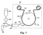
- Preferred methods of making multilayer polymer coatings in optical association with the optical elements of retroreflective articles can include aspects of the coating process shown in FIG. 7.
- the process can be performed at atmospheric pressure, optionally enclosing the coating region in a chamber 118 (e.g., for providing a clean environment, for providing an inert atmosphere, or for other such reasons), or at reduced pressure where chamber 118 is a vacuum chamber.
- Coating material 100 supplied in the form of a liquid monomer or pre-polymer, can be metered into evaporator 102 via pump 104 .
- the coating material 100 can be evaporated by one of several techniques, including flash evaporation and carrier gas collision vaporization.
- the coating material can be atomized into fine droplets through optional nozzle 122 , the droplets being subsequently vaporized inside evaporator 102 .
- a carrier gas 106 can be used to atomize the coating material and direct the droplets through nozzle 122 into evaporator 102 . Vaporization of the liquid coating material, or droplets of the liquid coating material, can be performed via contact with the heated walls of the evaporator 102 , contact by the optional carrier gas 106 (optionally heated by heater 108 ), or contact with some other heated surface. Any suitable operation for vaporizing the liquid coating material is contemplated for use in this invention.
- the coating material 100 can be directed through a coating die 110 and onto the optical elements 111 of retroreflective article 112 .
- a mask (not shown) can optionally be placed between the coating die 110 and the retroreflective article 112 to coat selected portions of the optical elements 111 .
- the surfaces of the optical elements 111 can be pretreated using an electrical discharge source 120 , such as a glow discharge source, silent discharge source, corona discharge source, or the like.
- the pretreatment step is optionally performed to modify the surface chemistry, for example, to improve adhesion of coating material to the retroreflective article, or for other such purposes.
- the surfaces of the optical elements 111 can optionally be pretreated with an adhesion promoter, as discussed below.
- Retroreflective article 112 is preferably maintained at a temperature at or below the condensation temperature of the monomer or pre-polymer vapor exiting the coating die 110. Retroreflective article 112 can be placed on, or otherwise disposed in temporary relation to, the surface of drum 114. The drum 114 allows the retroreflective article 112 to be moved past the coating die 110 at a selected rate to control the layer thickness. The drum 114 can also be maintained at a suitable bias temperature to maintain the retroreflective article 112 at or below the pre-polymer vapor's condensation temperature.
- the coating material After being applied on the optical elements 111, the coating material can be solidified.
- a curing source 116 can be provided downstream to the coating die 110 in the drum rotation direction (indicated by arrow 124 ). Any suitable curing source is contemplated by this invention, including electron beam sources, ultraviolet lamps, electrical discharge sources, heat lamps, and the like.
- a reflective coating that has two or more different polymer layers can be disposed in optical association with the optical elements 111 of a retroreflective article 112 by supplying at least a second coating material (not shown). After condensing the first coating material on the optical elements 111, a second coating material can be condensed on a previously deposited layer or layers, preferably after the previously deposited layer or layers have been cured. Addtional coating materials can be deposited as desired.
- inorganic, organometallic, and/or non-polymer layers can also be deposited using suitable methods, now known or later developed, including sputtering, chemical vapor deposition, electroplating, condensing from a solvent, and other such methods. These optional layers may be deposited directly on the optical elements before the polymer layers are formed, after the polymer layers are formed, or between polymer layers.
- a particularly preferred optional layer is an adhesion promoter coated between the optical elements of the retroreflective article and the polymer layers of the multilayer reflective coating.
- Adhesion promoters can be selected to improve adhesion between the multilayer reflective coating and the optical elements.
- a silane coupling agent can be used that promote adhesion between polymer layers of the multilayer reflective coatings of the present invention and optical elements which can be, for example, glass or ceramic microspheres, molded polycarbonate cube-corner elements, or other such optical elements.
- Exemplary silane coupling agents include aminopropyltriethoxysilane, glycidoxypropyltrimethoxysilane, methacryloxypropyltrimethoxysilane, and vinyltrimethoxysilane.
- titanate coupling agents can be used as adhesion promoters, examples of which include isopropyl tri(dioctyl)phosphato titanate, dimethacryl oxoethylene titanate, and titanium(tetraisopropoxide).
- Silazanes such as hexamethyldisilazane can also be used as adhesion promoters. Examples of silane coupling agents are disclosed in U.S. Patent 5,200,262 to Li.
- an apparatus that may be suitable for carrying out certain aspects of the method illustrated in FIG. 7 under vacuum conditions is commercially available on a custom-built basis from Delta V Technologies, Inc, Arlington, AZ. Apparatuses and portions of apparatuses that may be suitable for carrying out these and other aspects of the method illustrated in FIG. 7 are described in more detail in the cited documents.
- Exemplary monomers and oligomers suitable for use in the process shown in FIG. 7 include acrylates, methacrylates, acrylamides, methacrylamides, vinyl ethers, maleates, cinnamates, styrenes, olefins, vinyls, epoxides, silanes, melamines, hydroxy functional monomers, and amino functional monomers.
- Suitable monomers and oligomers can have more than one reactive group, and these reactive groups may be of different chemistries on the same molecule.
- Pre-polymers can be mixed to achieve a broad range of optical properties such as index of refraction in the layers of the reflective coating.
- the deposited pre-polymer materials can be applied in a substantially uniform, substantially continuous fashion, or they can be applied in a discontinuous manner, for example, as islands that cover only a selected portion or portions of the optical elements. Discontinuous applications can be provided in the form of characters, numerals, or other indicia by using, for example, a mask or other suitable techniques, including subsequent removal of undesired portions.
- Pre-polymer vapor deposition is particularly useful for forming thin films having a thickness of about 0.01 micrometers ( ⁇ m) to about 50 ⁇ m.
- Thicker layers can be formed by increasing the exposure time of the substrate to the vapor, by increasing the flow rate of the fluid composition to the atomizer, or by exposing the substrate to the coating material over multiple passes.
- Increasing the exposure time of the retroreflective article to the vapor can be achieved by adding multiple vapor sources to the system or by decreasing the speed at which the article travels through the system.
- Layered coatings of different materials can be formed by sequential coating depositions using a different coating material with each deposition, or by simultaneously depositing materials from different sources displaced from each other along the substrate travel path.
- the liquid monomer or pre-polymer layer can be cured.
- Curing the material generally involves irradiating the material on the substrate using visible light, ultraviolet radiation, electron beam radiation, ion radiation and/or free radicals (as from a plasma), or heat or any other suitable technique.
- the radiation source preferably is located downstream from the monomer or pre-polymer vapor source so that the coating material can be continuously applied and cured on the surface. Multiple revolutions of the substrate then continuously deposit and cure monomer vapor onto layers that were deposited and cured during previous revolutions.
- This invention also contemplates that curing occur simultaneously with condensing, for example, when the optical elements have a material that induces a curing reaction as the liquid monomer or pre-polymer material contacts the surface.
- condensing and curing can occur together, temporally or physically.
- Example set forth hereafter is merely illustrative of how to make various embodiments of the invention and how the embodiments generally perform.
- the beadcoat carrier was taped onto the chilled steel drum of a monomer vapor coating apparatus such as described in U.S. Pat. No. 4,842,893.
- the apparatus used a flash evaporation process to create a pre-polymer vapor that was coated using a vapor coating die.
- the vapor coating die directed the coating material onto the beadcoat carrier.
- the beadcoat carrier was mounted such that rotation of the drum exposed the embedded microspheres to, in order, a plasma treater, the vapor coating die, and an electron beam curing head. The deposition took place in a vacuum chamber.
- SBBPA sec-butyl(dibromophenyl acrylate)
- TRPGDA tripropylene glycol diacrylate
- a nitrogen gas flow of 570 milliliters per minute (ml/min) was applied to the 2000 Watt plasma treater.
- the room temperature TRPGDA liquid flow was 1.2 ml/min, and the heated SBBPA liquid flow was 1.1 ml/min.
- the monomer evaporator was maintained at 295 °C, and the vapor coating die was 285 °C.
- the vacuum chamber pressure was 2.2 ⁇ 10 -4 Torr.
- the electron beam curing gun used an accelerating voltage of 7.5 kV and 6 milliamps current.
- the alternating layers were applied by opening the SBBPA monomer flow valve at the monomer pump for one drum revolution then closing the SBBPA monomer flow valve and simultaneously opening the TRPGDA monomer flow valve for the next revolution.
- the beadcoat carrier coated with the 60 alternating layers was then coated with about 0.7 millimeters (mm) of a rapid-curing, general purpose epoxy adhesive as sold by ITW Devcon, Danvers, MA, under the trade designation POLYSTRATE 5-MINUTE EPOXY.
- the epoxy was allowed to cure at ambient conditions for 1 hour before stripping away the beadcoat carrier to give a retroreflective article that had a layer of glass microspheres and a multilayer reflective coating comprising 60 alternating polymer layers disposed behind the microspheres.
- glass microspheres were embedded into a beadcoat carrier and were coated with about 0.7 mm of the same epoxy without vapor depositing polymer layers onto the microspheres.
- the carrier sheet was stripped away after curing the epoxy for 1 hour.
- the retroreflectance of the Example and the comparative example were evaluated by measuring the percentage of incident light that was retroreflected by the samples. The measurements were performed as a function of wavelength for light in the visible spectrum (wavelengths of 400 nm to 800 nm).
- the retroreflectance from the Example that had the multilayer reflective coating was about a 2.5% to 3.5% throughout the range of wavelengths whereas the comparative sample without the multilayer reflective coating had about a 1.5% reflectance throughout the range. This indicated that the multilayer polymer coating acted as a reflector and improved the retroreflectivity relative to the comparative example.
Description
| Polymer or pre-polymer material | Supplier of monomer | Refractive index (monomer) | Refractive index (polymer) |
| Poly(vinyl naphthalene) | Aldrich (Milwaukee, WI) | -- | 1.6818 |
| Poly(styrene) | Aldrich | 1.547 | 1.592 |
| Poly(lauryl methacrylate) | Aldrich | 1.445 | 1.474 |
| Poly(trimethyl cylclohexyl methacrylate) | Aldrich | 1.456 | 1.485 |
| Poly(pentafluoro-styrene) | Aldrich | 1.406 | -- |
| Poly(trifluoroethyl methacrylate) | Aldrich | 1.361 | 1.437 |
| Poly(dibromopropene) | Aldrich | 1.5573 | -- |
| Poly(benzyl methacrylate) | Aldrich | 1.512 | 1.568 |
| Poly(ethylene glycol phenyl ether acrylate) | Aldrich | 1.518 | -- |
| Poly(pentadecafluoro-octyl acrylate) | 3M (St. Paul, MN) | 1.328 | 1.339 |
| Poly(ortho-sec-butyl dibromophenyl acrylate) | 3M | 1.562 | 1.594 |
| Ethoxylated trimethylol-propane triacrylate | Sartomer (Exton, PA) | 1.4695 | -- |
| Tris(2-hydroxy ethyl) isocyanurate triacrylate | Sartomer | 1.4489 | -- |
| Ethoxylated Bisphenol A diacrylate | Sartomer | 1.4933 | -- |
| 1,6 hexanediol diacrylate | Sartomer | 1.456 | -- |
| Isooctyl acrylate | Sartomer | 1.4346 | -- |
| Isobornyl acrylate | Sartomer | 1.4738 | -- |
| Tripropylene glycol diacrylate | Sartomer | 1.44 | -- |
Claims (10)
- A retroreflective article that comprises:(a) a layer of optical elements; and(b) a reflective coating that is disposed to conform to the optical elements and positioned relative to the optical elements such that hight transmitted through the optical elements is reflected by the reflective coating back into the optical elements, the reflective coating comprising a plurality of layers wherein (i) at least two adjacent layers have different refractive indices, and (ii) the reflective coating includes multiple polymer layers that each have an average thickness that is less than about 10% of an average size of the optical elements.
- A retroreflective article that comprises:(a) a layer of optical elements; and(b) a reflective coating disposed to conform to the optical elements and positioned relative to the optical elements such that high tramsmitted through the optical elements is reflected by the reflective coating back into the optical elements, the reflective coating comprising a plurality of polymer layers, the polymer layers including a first polymer material having a first index of refraction and a second polymer material having a second index of refraction different from the first index of refraction, and wherein each of the polymer layers has an average thickness that is less than 10% of an average size of the optical elements.
- The retroreflective article of claims 1 or 2, wherein the optical elements include microspheres or cube-corner elements.
- The retroreflective article of claims 1 or 2, wherein the reflective coating has 2 to 200 layers.
- The retroreflective article of claims 1 or 2, wherein at least two adjacent layers of the reflective coating have indices of refraction that differ by at least 0.05.
- The retroreflective article of claims 1 or 2, wherein the reflective coating reflects visible light.
- The retroreflective article of claims 1 or 2, wherein the reflective coating has a first portion and a second portion, the first portion of the reflective coating having adjacent layers that have different indices of refraction and optical thicknesses selected to redirect light in a first selected wavelength band from a first area of the retroreflective article, and the second portion of the reflective coating having adjacent layers that have different indices of refraction and optical thicknesses selected to redirect light in a second selected wavelength band from a second area of the retroreflective article.
- The retroreflective article of claims 1 or 2, wherein the reflective coating further comprises a non-polymer layer that is a metal oxide layer, an inorganic dielectric layer, an organometallic layer, or a ceramic layer.
- The retroreflective article of claim 1, wherein the reflective coating further comprises alternating layers of a polymeric material that has a first index of refraction and a non-polymer material that has a second index of refraction different from the first index of refraction, wherein the non-polymer material comprises a metal oxide, inorganic dielectric, organometallic, or ceramic material.
- The retroreflective article of claims 1 or 2, wherein each of the plurality of layers of the reflective coating has an average thickness that is less than about 2 µm.
Applications Claiming Priority (3)
| Application Number | Priority Date | Filing Date | Title |
|---|---|---|---|
| US259100 | 1999-02-26 | ||
| US09/259,100 US6172810B1 (en) | 1999-02-26 | 1999-02-26 | Retroreflective articles having polymer multilayer reflective coatings |
| PCT/US1999/011646 WO2000050931A1 (en) | 1999-02-26 | 1999-05-27 | Retroreflective articles having polymer multilayer reflective coatings |
Publications (2)
| Publication Number | Publication Date |
|---|---|
| EP1155346A1 EP1155346A1 (en) | 2001-11-21 |
| EP1155346B1 true EP1155346B1 (en) | 2003-01-22 |
Family
ID=22983541
Family Applications (1)
| Application Number | Title | Priority Date | Filing Date |
|---|---|---|---|
| EP99925887A Expired - Lifetime EP1155346B1 (en) | 1999-02-26 | 1999-05-27 | Retroreflective articles having polymer multilayer reflective coatings |
Country Status (11)
| Country | Link |
|---|---|
| US (4) | US6172810B1 (en) |
| EP (1) | EP1155346B1 (en) |
| JP (1) | JP2002538485A (en) |
| KR (1) | KR100609302B1 (en) |
| CN (1) | CN1158545C (en) |
| AU (1) | AU4208899A (en) |
| CA (1) | CA2362637A1 (en) |
| DE (1) | DE69905083T2 (en) |
| HK (1) | HK1043195A1 (en) |
| TW (1) | TWI292368B (en) |
| WO (1) | WO2000050931A1 (en) |
Families Citing this family (161)
| Publication number | Priority date | Publication date | Assignee | Title |
|---|---|---|---|---|
| CA2353506A1 (en) * | 1998-11-02 | 2000-05-11 | 3M Innovative Properties Company | Transparent conductive oxides for plastic flat panel displays |
| US6172810B1 (en) * | 1999-02-26 | 2001-01-09 | 3M Innovative Properties Company | Retroreflective articles having polymer multilayer reflective coatings |
| US6503564B1 (en) * | 1999-02-26 | 2003-01-07 | 3M Innovative Properties Company | Method of coating microstructured substrates with polymeric layer(s), allowing preservation of surface feature profile |
| JP3971529B2 (en) * | 1999-03-03 | 2007-09-05 | 日本カーバイド工業株式会社 | Retroreflective sheet |
| US6548164B1 (en) * | 1999-06-30 | 2003-04-15 | 3M Innovative Properties Company | Removable sheeting |
| US6590711B1 (en) | 2000-04-03 | 2003-07-08 | 3M Innovative Properties Co. | Light directing construction having corrosion resistant feature |
| US20090191342A1 (en) * | 1999-10-25 | 2009-07-30 | Vitex Systems, Inc. | Method for edge sealing barrier films |
| US6623861B2 (en) * | 2001-04-16 | 2003-09-23 | Battelle Memorial Institute | Multilayer plastic substrates |
| US20100330748A1 (en) * | 1999-10-25 | 2010-12-30 | Xi Chu | Method of encapsulating an environmentally sensitive device |
| US20070196682A1 (en) * | 1999-10-25 | 2007-08-23 | Visser Robert J | Three dimensional multilayer barrier and method of making |
| US6866901B2 (en) | 1999-10-25 | 2005-03-15 | Vitex Systems, Inc. | Method for edge sealing barrier films |
| US6413645B1 (en) | 2000-04-20 | 2002-07-02 | Battelle Memorial Institute | Ultrabarrier substrates |
| US6521324B1 (en) | 1999-11-30 | 2003-02-18 | 3M Innovative Properties Company | Thermal transfer of microstructured layers |
| US6582777B1 (en) * | 2000-02-17 | 2003-06-24 | Applied Materials Inc. | Electron beam modification of CVD deposited low dielectric constant materials |
| US6735789B2 (en) | 2000-07-31 | 2004-05-18 | Southern Mills, Inc. | Reflective printing on flame resistant fabrics |
| US6892949B2 (en) * | 2000-12-29 | 2005-05-17 | Siemens Logistics And Assembly Systems Inc. | Low visual impact labeling method and system |
| ATE413269T1 (en) * | 2001-07-16 | 2008-11-15 | Massachusetts Inst Technology | METHOD FOR PRODUCING FIBER OPTICAL FIBERS |
| US7272285B2 (en) * | 2001-07-16 | 2007-09-18 | Massachusetts Institute Of Technology | Fiber waveguides and methods of making the same |
| US6789905B2 (en) * | 2001-08-17 | 2004-09-14 | Basf Corporation | Method of providing a retroreflective coating system through wet-on-wet application and a retroreflective coating system thereof |
| US20090208754A1 (en) * | 2001-09-28 | 2009-08-20 | Vitex Systems, Inc. | Method for edge sealing barrier films |
| US6632325B2 (en) * | 2002-02-07 | 2003-10-14 | Applied Materials, Inc. | Article for use in a semiconductor processing chamber and method of fabricating same |
| US8808457B2 (en) | 2002-04-15 | 2014-08-19 | Samsung Display Co., Ltd. | Apparatus for depositing a multilayer coating on discrete sheets |
| US8900366B2 (en) * | 2002-04-15 | 2014-12-02 | Samsung Display Co., Ltd. | Apparatus for depositing a multilayer coating on discrete sheets |
| US6818291B2 (en) | 2002-08-17 | 2004-11-16 | 3M Innovative Properties Company | Durable transparent EMI shielding film |
| US6933051B2 (en) * | 2002-08-17 | 2005-08-23 | 3M Innovative Properties Company | Flexible electrically conductive film |
| US6929864B2 (en) * | 2002-08-17 | 2005-08-16 | 3M Innovative Properties Company | Extensible, visible light-transmissive and infrared-reflective film and methods of making and using the film |
| US7215473B2 (en) * | 2002-08-17 | 2007-05-08 | 3M Innovative Properties Company | Enhanced heat mirror films |
| AU2003297588A1 (en) * | 2002-12-02 | 2004-06-23 | 3M Innovative Properties Company | Illumination system using a plurality of light sources |
| KR20050103200A (en) * | 2003-01-27 | 2005-10-27 | 쓰리엠 이노베이티브 프로퍼티즈 컴파니 | Phosphor based light source component and method of making |
| US7118438B2 (en) * | 2003-01-27 | 2006-10-10 | 3M Innovative Properties Company | Methods of making phosphor based light sources having an interference reflector |
| US7210977B2 (en) | 2003-01-27 | 2007-05-01 | 3M Innovative Properties Comapny | Phosphor based light source component and method of making |
| US7091653B2 (en) | 2003-01-27 | 2006-08-15 | 3M Innovative Properties Company | Phosphor based light sources having a non-planar long pass reflector |
| US20040145312A1 (en) * | 2003-01-27 | 2004-07-29 | 3M Innovative Properties Company | Phosphor based light source having a flexible short pass reflector |
| US7245072B2 (en) * | 2003-01-27 | 2007-07-17 | 3M Innovative Properties Company | Phosphor based light sources having a polymeric long pass reflector |
| US7091661B2 (en) * | 2003-01-27 | 2006-08-15 | 3M Innovative Properties Company | Phosphor based light sources having a reflective polarizer |
| US20040159900A1 (en) * | 2003-01-27 | 2004-08-19 | 3M Innovative Properties Company | Phosphor based light sources having front illumination |
| US7312560B2 (en) * | 2003-01-27 | 2007-12-25 | 3M Innovative Properties | Phosphor based light sources having a non-planar long pass reflector and method of making |
| US7648925B2 (en) * | 2003-04-11 | 2010-01-19 | Vitex Systems, Inc. | Multilayer barrier stacks and methods of making multilayer barrier stacks |
| US7510913B2 (en) * | 2003-04-11 | 2009-03-31 | Vitex Systems, Inc. | Method of making an encapsulated plasma sensitive device |
| US20070006493A1 (en) * | 2003-05-12 | 2007-01-11 | Arnold Eberwein | Illuminated license plate for vehicles and vehicle provided with the same |
| US20070031641A1 (en) * | 2003-09-05 | 2007-02-08 | 3M Innovative Properties Company | License plate for back illumination and method for making same |
| US20050116635A1 (en) * | 2003-12-02 | 2005-06-02 | Walson James E. | Multiple LED source and method for assembling same |
| US20050116235A1 (en) * | 2003-12-02 | 2005-06-02 | Schultz John C. | Illumination assembly |
| US7456805B2 (en) * | 2003-12-18 | 2008-11-25 | 3M Innovative Properties Company | Display including a solid state light device and method using same |
| BRPI0418341A (en) * | 2003-12-30 | 2007-05-02 | 3M Innovative Properties Co | color-changing retroreflective article and method for producing a color-changing retroreflective article |
| US7142375B2 (en) * | 2004-02-12 | 2006-11-28 | Nanoopto Corporation | Films for optical use and methods of making such films |
| PL1584518T3 (en) * | 2004-04-07 | 2008-03-31 | 3M Innovative Properties Co | License plate assembly comprising light source and backlit license plate |
| US7349589B2 (en) * | 2004-04-08 | 2008-03-25 | Omniguide, Inc. | Photonic crystal fibers and medical systems including photonic crystal fibers |
| US7167622B2 (en) * | 2004-04-08 | 2007-01-23 | Omniguide, Inc. | Photonic crystal fibers and medical systems including photonic crystal fibers |
| US7331954B2 (en) | 2004-04-08 | 2008-02-19 | Omniguide, Inc. | Photonic crystal fibers and medical systems including photonic crystal fibers |
| WO2005114268A2 (en) * | 2004-05-12 | 2005-12-01 | Reflexite Corporation | Retroreflective structures |
| US20060002108A1 (en) | 2004-06-30 | 2006-01-05 | Ouderkirk Andrew J | Phosphor based illumination system having a short pass reflector and method of making same |
| US7204631B2 (en) * | 2004-06-30 | 2007-04-17 | 3M Innovative Properties Company | Phosphor based illumination system having a plurality of light guides and an interference reflector |
| US7255469B2 (en) * | 2004-06-30 | 2007-08-14 | 3M Innovative Properties Company | Phosphor based illumination system having a light guide and an interference reflector |
| US7204630B2 (en) * | 2004-06-30 | 2007-04-17 | 3M Innovative Properties Company | Phosphor based illumination system having a plurality of light guides and an interference reflector |
| US7182498B2 (en) * | 2004-06-30 | 2007-02-27 | 3M Innovative Properties Company | Phosphor based illumination system having a plurality of light guides and an interference reflector |
| US7213958B2 (en) * | 2004-06-30 | 2007-05-08 | 3M Innovative Properties Company | Phosphor based illumination system having light guide and an interference reflector |
| US20060040575A1 (en) * | 2004-08-18 | 2006-02-23 | Kelleher Karen A | Reflective printing on flame resistant fabrics |
| US7256057B2 (en) * | 2004-09-11 | 2007-08-14 | 3M Innovative Properties Company | Methods for producing phosphor based light sources |
| US7252396B2 (en) * | 2004-11-16 | 2007-08-07 | 3M Innovative Properties Company | Retroreflective article having at least one valve and method of making same |
| JP2008525862A (en) * | 2004-12-28 | 2008-07-17 | スリーエム イノベイティブ プロパティズ カンパニー | Prism retroreflective article having fluorine-containing or silicon-containing prism |
| US7195360B2 (en) * | 2004-12-28 | 2007-03-27 | 3M Innovative Properties Company | Prismatic retroreflective article and method |
| JP4139395B2 (en) | 2005-02-17 | 2008-08-27 | シャープ株式会社 | Reflective display device |
| US7733310B2 (en) * | 2005-04-01 | 2010-06-08 | Prysm, Inc. | Display screens having optical fluorescent materials |
| US7474286B2 (en) * | 2005-04-01 | 2009-01-06 | Spudnik, Inc. | Laser displays using UV-excitable phosphors emitting visible colored light |
| US7791561B2 (en) * | 2005-04-01 | 2010-09-07 | Prysm, Inc. | Display systems having screens with optical fluorescent materials |
| US20060221022A1 (en) * | 2005-04-01 | 2006-10-05 | Roger Hajjar | Laser vector scanner systems with display screens having optical fluorescent materials |
| US8000005B2 (en) | 2006-03-31 | 2011-08-16 | Prysm, Inc. | Multilayered fluorescent screens for scanning beam display systems |
| US8089425B2 (en) * | 2006-03-03 | 2012-01-03 | Prysm, Inc. | Optical designs for scanning beam display systems using fluorescent screens |
| US7994702B2 (en) | 2005-04-27 | 2011-08-09 | Prysm, Inc. | Scanning beams displays based on light-emitting screens having phosphors |
| JP4890800B2 (en) * | 2005-06-29 | 2012-03-07 | スリーエム イノベイティブ プロパティズ カンパニー | Transparent wavelength selective retroreflector |
| US7767498B2 (en) | 2005-08-25 | 2010-08-03 | Vitex Systems, Inc. | Encapsulated devices and method of making |
| US7830075B2 (en) * | 2005-10-28 | 2010-11-09 | Hewlett-Packard Development Company, L.P. | Reflector for transmission of a desired band of wavelengths of electromagnetic radiation |
| GB2433637A (en) * | 2005-12-21 | 2007-06-27 | 3M Innovative Properties Co | Semi-transparent retroreflective material |
| KR20140121888A (en) * | 2005-12-29 | 2014-10-16 | 쓰리엠 이노베이티브 프로퍼티즈 컴파니 | Method for atomizing material for coating processes |
| GB0602105D0 (en) * | 2006-02-02 | 2006-03-15 | 3M Innovative Properties Co | License plate assembly |
| US8451195B2 (en) * | 2006-02-15 | 2013-05-28 | Prysm, Inc. | Servo-assisted scanning beam display systems using fluorescent screens |
| US7884816B2 (en) * | 2006-02-15 | 2011-02-08 | Prysm, Inc. | Correcting pyramidal error of polygon scanner in scanning beam display systems |
| US7863634B2 (en) * | 2006-06-12 | 2011-01-04 | 3M Innovative Properties Company | LED device with re-emitting semiconductor construction and reflector |
| US20080068295A1 (en) * | 2006-09-19 | 2008-03-20 | Hajjar Roger A | Compensation for Spatial Variation in Displayed Image in Scanning Beam Display Systems Using Light-Emitting Screens |
| US7963676B2 (en) * | 2006-10-23 | 2011-06-21 | Wu Kuohua Angus | Reflector window for use in a light lamp |
| US8013506B2 (en) * | 2006-12-12 | 2011-09-06 | Prysm, Inc. | Organic compounds for adjusting phosphor chromaticity |
| EP2125361B1 (en) | 2006-12-28 | 2019-01-23 | 3M Innovative Properties Company | Nucleation layer for thin film metal layer formation |
| WO2008116123A1 (en) * | 2007-03-20 | 2008-09-25 | Spudnik, Inc. | Delivering and displaying advertisement or other application data to display systems |
| DE102007052325A1 (en) * | 2007-03-29 | 2009-05-07 | Erk Eckrohrkessel Gmbh | Method for the sliding temperature control of chemical substances with defined inlet and outlet temperatures in a heater and device for carrying out the method |
| US8169454B1 (en) | 2007-04-06 | 2012-05-01 | Prysm, Inc. | Patterning a surface using pre-objective and post-objective raster scanning systems |
| US7697183B2 (en) * | 2007-04-06 | 2010-04-13 | Prysm, Inc. | Post-objective scanning beam systems |
| WO2008144673A2 (en) | 2007-05-17 | 2008-11-27 | Spudnik, Inc. | Multilayered screens with light-emitting stripes for scanning beam display systems |
| EP2000786B1 (en) * | 2007-06-06 | 2018-11-07 | Rheinmetall Defence Electronics GmbH | Thermal imaging device with calibrating functionality |
| CN101680977A (en) * | 2007-06-19 | 2010-03-24 | 株式会社丸仁 | Iridescent reflected light emitting retroreflective material |
| US7878657B2 (en) * | 2007-06-27 | 2011-02-01 | Prysm, Inc. | Servo feedback control based on invisible scanning servo beam in scanning beam display systems with light-emitting screens |
| US8556430B2 (en) | 2007-06-27 | 2013-10-15 | Prysm, Inc. | Servo feedback control based on designated scanning servo beam in scanning beam display systems with light-emitting screens |
| JP5314013B2 (en) * | 2007-07-03 | 2013-10-16 | スリーエム イノベイティブ プロパティズ カンパニー | Backlight assembly having a transmissive optical film (OPTICAL FILM) |
| US7547105B2 (en) * | 2007-07-16 | 2009-06-16 | 3M Innovative Properties Company | Prismatic retroreflective article with cross-linked image layer and method of making same |
| US20090027775A1 (en) * | 2007-07-26 | 2009-01-29 | Nilsen Robert B | Multiple layer reflective tag |
| US8235537B2 (en) * | 2007-08-31 | 2012-08-07 | The United States Of America, As Represented By The Secretary Of The Navy | Plasmonic retroreflectors |
| JP2009098400A (en) * | 2007-10-17 | 2009-05-07 | Nippon Carbide Ind Co Inc | Optical sheet |
| EP2242656A2 (en) * | 2007-12-21 | 2010-10-27 | 3M Innovative Properties Company | Retroreflective security articles |
| EP2103972B1 (en) | 2008-03-20 | 2014-04-23 | 3M Innovative Properties Company | Light device comprising light guide |
| US8596809B2 (en) * | 2008-05-30 | 2013-12-03 | 3M Innovative Properties Company | Suspended optical film |
| WO2009146446A1 (en) * | 2008-05-30 | 2009-12-03 | Reflexite Corporation | Ultraviolet retroreflectors |
| US8350451B2 (en) * | 2008-06-05 | 2013-01-08 | 3M Innovative Properties Company | Ultrathin transparent EMI shielding film comprising a polymer basecoat and crosslinked polymer transparent dielectric layer |
| US7869112B2 (en) * | 2008-07-25 | 2011-01-11 | Prysm, Inc. | Beam scanning based on two-dimensional polygon scanner for display and other applications |
| KR20110098781A (en) * | 2008-12-08 | 2011-09-01 | 쓰리엠 이노베이티브 프로퍼티즈 컴파니 | Protective overlay bearing a graphic and retroreflective articles comprising the overlay |
| JP2012511177A (en) * | 2008-12-08 | 2012-05-17 | スリーエム イノベイティブ プロパティズ カンパニー | Prism-like retroreflective article having figure and method for producing the same |
| US8865293B2 (en) | 2008-12-15 | 2014-10-21 | 3M Innovative Properties Company | Optically active materials and articles and systems in which they may be used |
| US9184410B2 (en) | 2008-12-22 | 2015-11-10 | Samsung Display Co., Ltd. | Encapsulated white OLEDs having enhanced optical output |
| US9337446B2 (en) * | 2008-12-22 | 2016-05-10 | Samsung Display Co., Ltd. | Encapsulated RGB OLEDs having enhanced optical output |
| US20100167002A1 (en) * | 2008-12-30 | 2010-07-01 | Vitex Systems, Inc. | Method for encapsulating environmentally sensitive devices |
| JP2010225373A (en) * | 2009-03-23 | 2010-10-07 | Sony Corp | Color conversion sheet, illumination device, and display device |
| KR101741863B1 (en) | 2009-10-16 | 2017-05-30 | 쓰리엠 이노베이티브 프로퍼티즈 캄파니 | Prismatic retroreflective sheeting with reduced retroreflectivity of infra-red light |
| KR101741288B1 (en) | 2009-10-16 | 2017-05-29 | 쓰리엠 이노베이티브 프로퍼티즈 캄파니 | Retroreflective sheeting and license plate with reduced retroreflectivity at high entrance angles |
| US9063299B2 (en) | 2009-12-15 | 2015-06-23 | Omni Guide, Inc. | Two-part surgical waveguide |
| US8590338B2 (en) | 2009-12-31 | 2013-11-26 | Samsung Mobile Display Co., Ltd. | Evaporator with internal restriction |
| EP2343198A1 (en) | 2010-01-12 | 2011-07-13 | 3M Innovative Properties Company | Security laminate, method of making a security laminate, and article comprising a security laminate |
| JP5608385B2 (en) * | 2010-02-08 | 2014-10-15 | デクセリアルズ株式会社 | OPTICAL BODY, MANUFACTURING METHOD THEREFOR, WINDOW MATERIAL, JOINT, AND sunshine blocking device |
| JP6074128B2 (en) * | 2010-04-15 | 2017-02-01 | デクセリアルズ株式会社 | Optical body and manufacturing method thereof, solar shading member, window material, interior member and fitting |
| CN102893188B (en) | 2010-05-25 | 2016-11-02 | 3M创新有限公司 | Exposed lens Retroflective article |
| US8988638B2 (en) | 2011-05-25 | 2015-03-24 | Yingqiu Jiang | Polarizing retro-reflective sheeting comprising a cholesteric liquid crystal polymer film |
| WO2012166462A2 (en) | 2011-05-31 | 2012-12-06 | 3M Innovative Properties Company | Method for making microstructured tools having interspersed topographies, and articles produced therefrom |
| EP2714358B1 (en) | 2011-05-31 | 2020-02-19 | 3M Innovative Properties Company | Methods for making differentially pattern cured microstructured articles |
| BR112014002320A2 (en) | 2011-08-05 | 2017-03-01 | 3M Innovative Properties Co | steam processing systems and methods |
| US8809811B2 (en) | 2012-09-13 | 2014-08-19 | Prysm, Inc. | Reduction of intensity ringing in fluorescent displays |
| KR20140066449A (en) * | 2012-11-23 | 2014-06-02 | 삼성디스플레이 주식회사 | Reflect sheet, backlight unit, liquid crystal display device and manufacturing method thereof |
| US9839712B2 (en) * | 2012-12-21 | 2017-12-12 | 3M Innovative Properties Company | Systems and methods for determining the cleanliness of a surface |
| WO2015061065A1 (en) | 2013-10-24 | 2015-04-30 | 3M Innovative Properties Company | Retroreflective articles with anti-staining properties |
| US10261223B2 (en) | 2014-01-31 | 2019-04-16 | Canon Usa, Inc. | System and method for fabrication of miniature endoscope using nanoimprint lithography |
| CN106415336B (en) | 2014-04-30 | 2020-12-04 | 3M创新有限公司 | Stain resistant retroreflective article |
| WO2015171406A1 (en) * | 2014-05-09 | 2015-11-12 | 3M Innovative Properties Company | Colored retroreflective articles |
| EP3191879A1 (en) | 2014-09-10 | 2017-07-19 | 3M Innovative Properties Company | Exposed lens retroreflective articles comprising a self-assembled dielectric mirror |
| JP2016118584A (en) | 2014-12-18 | 2016-06-30 | スリーエム イノベイティブ プロパティズ カンパニー | Retroreflective sheet, license plate, and manufacturing method therefor |
| US10345495B2 (en) | 2014-12-30 | 2019-07-09 | 3M Innovative Properties Company | Stain resistant retroreflective articles |
| US10925268B1 (en) * | 2015-03-13 | 2021-02-23 | Ray D. Flasco | Inside corner cubic surface reflector fishing lure |
| US10590559B2 (en) * | 2015-03-13 | 2020-03-17 | Apple Inc. | Anodizing and pre-anodizing processes based on incoming laser textured part |
| KR102028851B1 (en) | 2015-12-08 | 2019-10-04 | 쓰리엠 이노베이티브 프로퍼티즈 캄파니 | Prismatic retroreflective sheets comprising infrared absorbing material |
| US11602948B2 (en) | 2015-12-08 | 2023-03-14 | 3M Innovative Properties Company | Articles including infrared absorptive material and comprising radiation-treated and non-radiation-treated regions |
| CN108430638B (en) | 2015-12-22 | 2021-06-08 | 3M创新有限公司 | Rod-and-channel membranes for sample distribution |
| CN108431576B (en) | 2015-12-28 | 2020-09-15 | 3M创新有限公司 | Cartridge for sample dispensing |
| JP6634330B2 (en) * | 2016-04-05 | 2020-01-22 | 株式会社ジャパンディスプレイ | Display device |
| CN106560734A (en) | 2016-06-01 | 2017-04-12 | 杭州飞像科技有限公司 | Application of aerial imaging element in prompter, and prompter |
| CN106560733B (en) * | 2016-06-01 | 2022-05-24 | 杭州飞像科技有限公司 | Aerial imaging element, aerial imaging display device and application thereof |
| CN108181712A (en) * | 2016-12-08 | 2018-06-19 | 未来(北京)黑科技有限公司 | For the system being imaged in the air |
| CN108181713A (en) * | 2016-12-08 | 2018-06-19 | 未来(北京)黑科技有限公司 | For the system being imaged in the air |
| US10684492B2 (en) | 2016-12-08 | 2020-06-16 | Futurus Technology Co., Ltd. | System for imaging in the air |
| CN108181714A (en) * | 2016-12-08 | 2018-06-19 | 未来(北京)黑科技有限公司 | For the system being imaged in the air |
| WO2018217519A1 (en) | 2017-05-25 | 2018-11-29 | 3M Innovative Properties Company | Cube corner retroreflective articles with tailored retroreflectivity and methods of making |
| CN111247460A (en) | 2017-08-29 | 2020-06-05 | 艾利丹尼森公司 | Retroreflective sheeting for projector-based display systems |
| US11366252B2 (en) | 2017-10-27 | 2022-06-21 | 3M Innovative Properties Company | Retroreflective article comprising locally-laminated reflective layers |
| EP3701300A4 (en) | 2017-10-27 | 2021-08-25 | 3M Innovative Properties Company | Retroreflective article comprising embedded reflective layers |
| CN111344606A (en) | 2017-10-27 | 2020-06-26 | 3M创新有限公司 | Retroreflective articles including retroreflective elements comprising primary and secondary reflective layers |
| WO2019084287A1 (en) * | 2017-10-27 | 2019-05-02 | 3M Innovative Properties Company | Exposed-lens retroreflective article comprising color layers comprising bi-layer structures |
| US20210364678A1 (en) * | 2018-03-30 | 2021-11-25 | 3M Innovative Properties Company | Retroreflective article including a conformal wavelength-selective radiation absorbing coating layer, and methods of making same |
| CN112385321A (en) | 2018-06-28 | 2021-02-19 | 3M创新有限公司 | Method for preparing metal pattern on flexible substrate |
| JP2020008797A (en) * | 2018-07-12 | 2020-01-16 | 株式会社小松プロセス | Retroreflection material, retroreflection object, retroreflective ink or paint, manufacturing method of retroreflective sheet, and manufacturing method of retroreflection object |
| US11001979B2 (en) | 2018-08-13 | 2021-05-11 | Vergence Automation, Inc. | Methods and apparatus for ultrawide entrance angle reflective articles for use with autonomous vehicle machine vision systems |
| US11762133B1 (en) | 2018-09-13 | 2023-09-19 | Vergence Automation, Inc. | Retroreflective materials and articles incorporating near-ideal total internal retroreflective elements |
| CN110187581A (en) * | 2019-05-13 | 2019-08-30 | 安徽屹珹新材料科技有限公司 | A kind of colorful optical film and its preparation method and application structure |
| CN110058330A (en) * | 2019-05-13 | 2019-07-26 | 安徽屹珹新材料科技有限公司 | A kind of colorful optical film and its preparation method and application structure |
| KR102225452B1 (en) * | 2019-07-04 | 2021-03-08 | 윤세원 | Retroreflective sheet |
| KR102212285B1 (en) * | 2019-08-14 | 2021-02-04 | (주)에이치제이 | Retroreflective sheet and method thereof |
| KR102277850B1 (en) * | 2019-10-17 | 2021-07-16 | (주)에이치제이 | Retroreflective sheet and fabricating method thereof |
Family Cites Families (61)
| Publication number | Priority date | Publication date | Assignee | Title |
|---|---|---|---|---|
| US1175224A (en) | 1916-03-14 | Pboces of | ||
| US2214369A (en) | 1939-01-30 | 1940-09-10 | American Automatic Devices Co | Reflector |
| US2379741A (en) | 1943-01-23 | 1945-07-03 | Minnesota Mining & Mfg | Reflex light reflector |
| US2354049A (en) | 1944-01-19 | 1944-07-18 | Minnesota Mining & Mfg | Backless reflex light reflector |
| US2383884A (en) | 1944-06-12 | 1945-08-28 | Minnesota Mining & Mfg | Colored reflex light reflector |
| US2440584A (en) | 1944-06-19 | 1948-04-27 | Minnesota Mining & Mfg | Lenticular reflex reflector sheet and method of making the same |
| US2407680A (en) | 1945-03-02 | 1946-09-17 | Minnesota Mining & Mfg | Reflex light reflector |
| US2568126A (en) | 1945-08-10 | 1951-09-18 | Prismo Products Inc | Method of making reflecting signs by laminating |
| US2543800A (en) | 1947-12-05 | 1951-03-06 | Minnesota Mining & Mfg | Reflex light reflector |
| US3684348A (en) | 1970-09-29 | 1972-08-15 | Rowland Dev Corp | Retroreflective material |
| US3810804A (en) | 1970-09-29 | 1974-05-14 | Rowland Dev Corp | Method of making retroreflective material |
| US3700478A (en) | 1970-11-09 | 1972-10-24 | Minnesota Mining & Mfg | Microspheres having an antireflection coating and their use |
| US3700305A (en) | 1970-12-14 | 1972-10-24 | Minnesota Mining & Mfg | Retroreflective microspheres having a dielectric mirror on a portion of their surface and retroreflective constructions containing such microspheres |
| US4025159A (en) | 1976-02-17 | 1977-05-24 | Minnesota Mining And Manufacturing Company | Cellular retroreflective sheeting |
| US4192576A (en) | 1978-11-20 | 1980-03-11 | Minnesota Mining And Manufacturing Company | Ultra-high-index glass microspheres and products made therefrom |
| US4310584A (en) | 1979-12-26 | 1982-01-12 | The Mearl Corporation | Multilayer light-reflecting film |
| US4648932A (en) | 1983-04-11 | 1987-03-10 | Minnesota Mining And Manufacturing Company | High-angularity retroreflective sheeting and method for manufacture |
| US4588258A (en) | 1983-09-12 | 1986-05-13 | Minnesota Mining And Manufacturing Company | Cube-corner retroreflective articles having wide angularity in multiple viewing planes |
| US5018048A (en) | 1983-12-19 | 1991-05-21 | Spectrum Control, Inc. | Miniaturized monolithic multi-layer capacitor and apparatus and method for making |
| US5097800A (en) | 1983-12-19 | 1992-03-24 | Spectrum Control, Inc. | High speed apparatus for forming capacitors |
| US4842893A (en) | 1983-12-19 | 1989-06-27 | Spectrum Control, Inc. | High speed process for coating substrates |
| US5125138A (en) | 1983-12-19 | 1992-06-30 | Spectrum Control, Inc. | Miniaturized monolithic multi-layer capacitor and apparatus and method for making same |
| US5032461A (en) | 1983-12-19 | 1991-07-16 | Spectrum Control, Inc. | Method of making a multi-layered article |
| US4722515A (en) | 1984-11-06 | 1988-02-02 | Spectrum Control, Inc. | Atomizing device for vaporization |
| EP0242460A1 (en) | 1985-01-18 | 1987-10-28 | SPECTRUM CONTROL, INC. (a Pennsylvania corporation) | Monomer atomizer for vaporization |
| EP0609683A1 (en) | 1985-05-07 | 1994-08-10 | Dai Nippon Insatsu Kabushiki Kaisha | Relief hologram and process for producing a relief hologram |
| US4703999A (en) | 1986-06-16 | 1987-11-03 | Minnesota Mining And Manufacturing Company | Wide-angle-reflective cube-corner retroreflective sheeting |
| US4954371A (en) | 1986-06-23 | 1990-09-04 | Spectrum Control, Inc. | Flash evaporation of monomer fluids |
| US4763985A (en) | 1986-08-01 | 1988-08-16 | Minnesota Mining And Manufacturing Company | Retroreflective sheet with enhanced brightness |
| US4775219A (en) | 1986-11-21 | 1988-10-04 | Minnesota Mining & Manufacturing Company | Cube-corner retroreflective articles having tailored divergence profiles |
| US4938563A (en) | 1986-11-21 | 1990-07-03 | Minnesota Mining And Manufacturing Company | High efficiency cube corner retroflective material |
| US4896943A (en) | 1987-05-13 | 1990-01-30 | Minnesota Mining And Manufacturing Company | Encapsulated-lens retroreflective sheeting having improved cover film |
| US5066098A (en) | 1987-05-15 | 1991-11-19 | Minnesota Mining And Manufacturing Company | Cellular encapsulated-lens high whiteness retroreflective sheeting with flexible cover sheet |
| US4895428A (en) | 1988-07-26 | 1990-01-23 | Minnesota Mining And Manufacturing Company | High efficiency retroreflective material |
| JPH03132603A (en) * | 1989-10-18 | 1991-06-06 | Matsushita Electric Ind Co Ltd | Polarizer |
| US5278694A (en) | 1990-01-11 | 1994-01-11 | The Dow Chemical Company | Optically dissimilar composition for polymeric reflective bodies |
| KR940701548A (en) | 1991-06-13 | 1994-05-28 | 게리 리 그리스월드 | Retroreflective polarizer |
| US5422756A (en) * | 1992-05-18 | 1995-06-06 | Minnesota Mining And Manufacturing Company | Backlighting system using a retroreflecting polarizer |
| US5260095A (en) | 1992-08-21 | 1993-11-09 | Battelle Memorial Institute | Vacuum deposition and curing of liquid monomers |
| US5339198A (en) | 1992-10-16 | 1994-08-16 | The Dow Chemical Company | All-polymeric cold mirror |
| GB9225270D0 (en) | 1992-12-03 | 1993-01-27 | Gec Ferranti Defence Syst | Depositing different materials on a substrate |
| JP3221771B2 (en) | 1993-06-11 | 2001-10-22 | 日本カーバイド工業株式会社 | Cube corner type retroreflective sheet |
| US5440446A (en) | 1993-10-04 | 1995-08-08 | Catalina Coatings, Inc. | Acrylate coating material |
| US5691846A (en) | 1993-10-20 | 1997-11-25 | Minnesota Mining And Manufacturing Company | Ultra-flexible retroreflective cube corner composite sheetings and methods of manufacture |
| US5450235A (en) | 1993-10-20 | 1995-09-12 | Minnesota Mining And Manufacturing Company | Flexible cube-corner retroreflective sheeting |
| US5614286A (en) | 1993-10-20 | 1997-03-25 | Minnesota Mining And Manufacturing Company | Conformable cube corner retroreflective sheeting |
| MY121195A (en) | 1993-12-21 | 2006-01-28 | Minnesota Mining & Mfg | Reflective polarizer with brightness enhancement |
| AU3693395A (en) | 1994-05-12 | 1995-12-05 | Minnesota Mining And Manufacturing Company | Retroreflective article and method of making same |
| US6083628A (en) | 1994-11-04 | 2000-07-04 | Sigma Laboratories Of Arizona, Inc. | Hybrid polymer film |
| US5877895A (en) | 1995-03-20 | 1999-03-02 | Catalina Coatings, Inc. | Multicolor interference coating |
| US5811183A (en) | 1995-04-06 | 1998-09-22 | Shaw; David G. | Acrylate polymer release coated sheet materials and method of production thereof |
| JP3629297B2 (en) | 1995-05-11 | 2005-03-16 | ミネソタ マイニング アンド マニュファクチャリング カンパニー | Retroreflective sheet and article having retroreflective performance |
| WO1997001440A1 (en) | 1995-06-26 | 1997-01-16 | Minnesota Mining And Manufacturing Company | Multilayer polymer film with additional coatings or layers |
| US5699188A (en) | 1995-06-26 | 1997-12-16 | Minnesota Mining And Manufacturing Co. | Metal-coated multilayer mirror |
| US5812317A (en) | 1995-10-26 | 1998-09-22 | Minnesota Mining And Manufacturing Company | Exposed lens retroreflective article having a polymeric intermediate layer disposed between microspheric and reflective layers |
| KR19980033213A (en) | 1996-10-31 | 1998-07-25 | 조셉제이.스위니 | How to reduce the generation of particulate matter in the sputtering chamber |
| US5932626A (en) | 1997-05-09 | 1999-08-03 | Minnesota Mining And Manufacturing Company | Optical product prepared from high index of refraction brominated monomers |
| US6224948B1 (en) | 1997-09-29 | 2001-05-01 | Battelle Memorial Institute | Plasma enhanced chemical deposition with low vapor pressure compounds |
| US6024455A (en) | 1998-01-13 | 2000-02-15 | 3M Innovative Properties Company | Reflective article with concealed retroreflective pattern |
| US6228434B1 (en) | 1998-12-16 | 2001-05-08 | Battelle Memorial Institute | Method of making a conformal coating of a microtextured surface |
| US6172810B1 (en) * | 1999-02-26 | 2001-01-09 | 3M Innovative Properties Company | Retroreflective articles having polymer multilayer reflective coatings |
-
1999
- 1999-02-26 US US09/259,100 patent/US6172810B1/en not_active Expired - Lifetime
- 1999-05-27 CA CA002362637A patent/CA2362637A1/en not_active Abandoned
- 1999-05-27 JP JP2000601471A patent/JP2002538485A/en not_active Withdrawn
- 1999-05-27 EP EP99925887A patent/EP1155346B1/en not_active Expired - Lifetime
- 1999-05-27 CN CNB998163651A patent/CN1158545C/en not_active Expired - Fee Related
- 1999-05-27 AU AU42088/99A patent/AU4208899A/en not_active Abandoned
- 1999-05-27 KR KR1020017010844A patent/KR100609302B1/en not_active IP Right Cessation
- 1999-05-27 DE DE69905083T patent/DE69905083T2/en not_active Expired - Fee Related
- 1999-05-27 WO PCT/US1999/011646 patent/WO2000050931A1/en active IP Right Grant
-
2000
- 2000-01-31 TW TW089101638A patent/TWI292368B/zh active
- 2000-04-10 US US09/545,931 patent/US6350034B1/en not_active Expired - Lifetime
- 2000-04-10 US US09/545,952 patent/US6224219B1/en not_active Expired - Lifetime
- 2000-07-26 US US09/625,796 patent/US6243201B1/en not_active Expired - Lifetime
-
2002
- 2002-04-12 HK HK02102789.9A patent/HK1043195A1/en unknown
Also Published As
| Publication number | Publication date |
|---|---|
| KR100609302B1 (en) | 2006-08-09 |
| CA2362637A1 (en) | 2000-08-31 |
| US6350034B1 (en) | 2002-02-26 |
| HK1043195A1 (en) | 2002-09-06 |
| CN1158545C (en) | 2004-07-21 |
| JP2002538485A (en) | 2002-11-12 |
| CN1338058A (en) | 2002-02-27 |
| EP1155346A1 (en) | 2001-11-21 |
| US6243201B1 (en) | 2001-06-05 |
| DE69905083T2 (en) | 2003-05-22 |
| AU4208899A (en) | 2000-09-14 |
| US6224219B1 (en) | 2001-05-01 |
| WO2000050931A1 (en) | 2000-08-31 |
| KR20010102392A (en) | 2001-11-15 |
| DE69905083D1 (en) | 2003-02-27 |
| TWI292368B (en) | 2008-01-11 |
| US6172810B1 (en) | 2001-01-09 |
Similar Documents
| Publication | Publication Date | Title |
|---|---|---|
| EP1155346B1 (en) | Retroreflective articles having polymer multilayer reflective coatings | |
| US7140741B2 (en) | Color shifting retroreflector and method of making same | |
| US7288309B2 (en) | Microstructured substrates with profile-preserving organometallic coatings | |
| KR100614059B1 (en) | Article exhibiting dry and wet retroreflectivity | |
| US5376431A (en) | Retroreflective microprism sheeting with silver/copper reflecting coating and method of making same | |
| KR960002305B1 (en) | Wide-angle-reflective cube-corner retroreflective sheeting | |
| EP0891569B1 (en) | Retroreflective sheeting with coated back surface | |
| US6139158A (en) | Retroreflective articles with multiple size prisms in multiple locations | |
| EP0840899A1 (en) | Retroreflective articles with muliple size prisms in multiple locations | |
| MXPA06007614A (en) | Color shifting retroreflector and method of making same |
Legal Events
| Date | Code | Title | Description |
|---|---|---|---|
| PUAI | Public reference made under article 153(3) epc to a published international application that has entered the european phase |
Free format text: ORIGINAL CODE: 0009012 |
|
| 17P | Request for examination filed |
Effective date: 20010919 |
|
| AK | Designated contracting states |
Kind code of ref document: A1 Designated state(s): DE FR GB IT |
|
| GRAG | Despatch of communication of intention to grant |
Free format text: ORIGINAL CODE: EPIDOS AGRA |
|
| 17Q | First examination report despatched |
Effective date: 20020205 |
|
| GRAG | Despatch of communication of intention to grant |
Free format text: ORIGINAL CODE: EPIDOS AGRA |
|
| GRAG | Despatch of communication of intention to grant |
Free format text: ORIGINAL CODE: EPIDOS AGRA |
|
| GRAH | Despatch of communication of intention to grant a patent |
Free format text: ORIGINAL CODE: EPIDOS IGRA |
|
| GRAH | Despatch of communication of intention to grant a patent |
Free format text: ORIGINAL CODE: EPIDOS IGRA |
|
| GRAH | Despatch of communication of intention to grant a patent |
Free format text: ORIGINAL CODE: EPIDOS IGRA |
|
| GRAH | Despatch of communication of intention to grant a patent |
Free format text: ORIGINAL CODE: EPIDOS IGRA |
|
| GRAA | (expected) grant |
Free format text: ORIGINAL CODE: 0009210 |
|
| AK | Designated contracting states |
Kind code of ref document: B1 Designated state(s): DE FR GB IT |
|
| REG | Reference to a national code |
Ref country code: GB Ref legal event code: FG4D |
|
| REF | Corresponds to: |
Ref document number: 69905083 Country of ref document: DE Date of ref document: 20030227 Kind code of ref document: P |
|
| ET | Fr: translation filed | ||
| PLBE | No opposition filed within time limit |
Free format text: ORIGINAL CODE: 0009261 |
|
| STAA | Information on the status of an ep patent application or granted ep patent |
Free format text: STATUS: NO OPPOSITION FILED WITHIN TIME LIMIT |
|
| 26N | No opposition filed |
Effective date: 20031023 |
|
| PGFP | Annual fee paid to national office [announced via postgrant information from national office to epo] |
Ref country code: GB Payment date: 20070525 Year of fee payment: 9 |
|
| PGFP | Annual fee paid to national office [announced via postgrant information from national office to epo] |
Ref country code: IT Payment date: 20070525 Year of fee payment: 9 |
|
| PGFP | Annual fee paid to national office [announced via postgrant information from national office to epo] |
Ref country code: FR Payment date: 20070517 Year of fee payment: 9 |
|
| PGFP | Annual fee paid to national office [announced via postgrant information from national office to epo] |
Ref country code: DE Payment date: 20080630 Year of fee payment: 10 |
|
| REG | Reference to a national code |
Ref country code: HK Ref legal event code: WD Ref document number: 1043195 Country of ref document: HK |
|
| GBPC | Gb: european patent ceased through non-payment of renewal fee |
Effective date: 20080527 |
|
| REG | Reference to a national code |
Ref country code: FR Ref legal event code: ST Effective date: 20090119 |
|
| PG25 | Lapsed in a contracting state [announced via postgrant information from national office to epo] |
Ref country code: FR Free format text: LAPSE BECAUSE OF NON-PAYMENT OF DUE FEES Effective date: 20080602 |
|
| PG25 | Lapsed in a contracting state [announced via postgrant information from national office to epo] |
Ref country code: GB Free format text: LAPSE BECAUSE OF NON-PAYMENT OF DUE FEES Effective date: 20080527 |
|
| PG25 | Lapsed in a contracting state [announced via postgrant information from national office to epo] |
Ref country code: IT Free format text: LAPSE BECAUSE OF NON-PAYMENT OF DUE FEES Effective date: 20080527 |
|
| PG25 | Lapsed in a contracting state [announced via postgrant information from national office to epo] |
Ref country code: DE Free format text: LAPSE BECAUSE OF NON-PAYMENT OF DUE FEES Effective date: 20091201 |