EP1156208A2 - An improved fuel injector - Google Patents
An improved fuel injector Download PDFInfo
- Publication number
- EP1156208A2 EP1156208A2 EP01304395A EP01304395A EP1156208A2 EP 1156208 A2 EP1156208 A2 EP 1156208A2 EP 01304395 A EP01304395 A EP 01304395A EP 01304395 A EP01304395 A EP 01304395A EP 1156208 A2 EP1156208 A2 EP 1156208A2
- Authority
- EP
- European Patent Office
- Prior art keywords
- needle
- valve seat
- injector
- face
- orifice
- Prior art date
- Legal status (The legal status is an assumption and is not a legal conclusion. Google has not performed a legal analysis and makes no representation as to the accuracy of the status listed.)
- Withdrawn
Links
- 239000000446 fuel Substances 0.000 title claims abstract description 111
- 238000000034 method Methods 0.000 claims abstract description 33
- 238000002485 combustion reaction Methods 0.000 claims abstract description 30
- 238000002347 injection Methods 0.000 claims abstract description 6
- 239000007924 injection Substances 0.000 claims abstract description 6
- 239000012530 fluid Substances 0.000 claims description 45
- 238000007789 sealing Methods 0.000 claims description 32
- 238000011144 upstream manufacturing Methods 0.000 claims description 16
- 230000001419 dependent effect Effects 0.000 claims description 14
- 238000000889 atomisation Methods 0.000 description 3
- 230000009286 beneficial effect Effects 0.000 description 2
- 230000005291 magnetic effect Effects 0.000 description 2
- 239000000463 material Substances 0.000 description 2
- 239000007921 spray Substances 0.000 description 2
- 239000012080 ambient air Substances 0.000 description 1
- 239000003989 dielectric material Substances 0.000 description 1
- 230000000694 effects Effects 0.000 description 1
- 239000003302 ferromagnetic material Substances 0.000 description 1
- 239000010763 heavy fuel oil Substances 0.000 description 1
- 239000000203 mixture Substances 0.000 description 1
- 238000012986 modification Methods 0.000 description 1
- 230000004048 modification Effects 0.000 description 1
- 239000007800 oxidant agent Substances 0.000 description 1
- 239000002245 particle Substances 0.000 description 1
- 238000000926 separation method Methods 0.000 description 1
- 229910001220 stainless steel Inorganic materials 0.000 description 1
- 239000010935 stainless steel Substances 0.000 description 1
Images


Classifications
-
- F—MECHANICAL ENGINEERING; LIGHTING; HEATING; WEAPONS; BLASTING
- F02—COMBUSTION ENGINES; HOT-GAS OR COMBUSTION-PRODUCT ENGINE PLANTS
- F02M—SUPPLYING COMBUSTION ENGINES IN GENERAL WITH COMBUSTIBLE MIXTURES OR CONSTITUENTS THEREOF
- F02M61/00—Fuel-injectors not provided for in groups F02M39/00 - F02M57/00 or F02M67/00
- F02M61/16—Details not provided for in, or of interest apart from, the apparatus of groups F02M61/02 - F02M61/14
- F02M61/18—Injection nozzles, e.g. having valve seats; Details of valve member seated ends, not otherwise provided for
- F02M61/1853—Orifice plates
-
- F—MECHANICAL ENGINEERING; LIGHTING; HEATING; WEAPONS; BLASTING
- F02—COMBUSTION ENGINES; HOT-GAS OR COMBUSTION-PRODUCT ENGINE PLANTS
- F02M—SUPPLYING COMBUSTION ENGINES IN GENERAL WITH COMBUSTIBLE MIXTURES OR CONSTITUENTS THEREOF
- F02M51/00—Fuel-injection apparatus characterised by being operated electrically
- F02M51/06—Injectors peculiar thereto with means directly operating the valve needle
- F02M51/061—Injectors peculiar thereto with means directly operating the valve needle using electromagnetic operating means
- F02M51/0625—Injectors peculiar thereto with means directly operating the valve needle using electromagnetic operating means characterised by arrangement of mobile armatures
- F02M51/0664—Injectors peculiar thereto with means directly operating the valve needle using electromagnetic operating means characterised by arrangement of mobile armatures having a cylindrically or partly cylindrically shaped armature, e.g. entering the winding; having a plate-shaped or undulated armature entering the winding
- F02M51/0671—Injectors peculiar thereto with means directly operating the valve needle using electromagnetic operating means characterised by arrangement of mobile armatures having a cylindrically or partly cylindrically shaped armature, e.g. entering the winding; having a plate-shaped or undulated armature entering the winding the armature having an elongated valve body attached thereto
-
- F—MECHANICAL ENGINEERING; LIGHTING; HEATING; WEAPONS; BLASTING
- F02—COMBUSTION ENGINES; HOT-GAS OR COMBUSTION-PRODUCT ENGINE PLANTS
- F02M—SUPPLYING COMBUSTION ENGINES IN GENERAL WITH COMBUSTIBLE MIXTURES OR CONSTITUENTS THEREOF
- F02M61/00—Fuel-injectors not provided for in groups F02M39/00 - F02M57/00 or F02M67/00
- F02M61/16—Details not provided for in, or of interest apart from, the apparatus of groups F02M61/02 - F02M61/14
- F02M61/18—Injection nozzles, e.g. having valve seats; Details of valve member seated ends, not otherwise provided for
Definitions
- This invention relates to injectors, and more particularly, to fuel injectors having a sac volume that minimises residual fuel after metering. This invention also relates to injectors having improved resistance to wear of their moving parts.
- Fuel injectors are commonly employed in internal combustion engines to provide precise metering of fuel for introduction into each combustion chamber. Additionally, the fuel injector atomises the fuel during injection, breaking the fuel into a large number of very small particles, increasing the surface area of the fuel being injected, and allowing the oxidiser, typically ambient air, to more thoroughly mix with the fuel prior to combustion. The precise metering and atomisation of the fuel reduces combustion emissions and increases the fuel efficiency of the engine.
- An electro-magnetic fuel injector typically utilises a solenoid assembly to supply an actuating force to a fuel metering valve.
- the fuel metering valve is a plunger style needle valve which reciprocates between a closed position, where the needle is seated in a valve seat to prevent fuel from escaping through a metering orifice into the combustion chamber, and an open position, where the needle is lifted from the valve seat, allowing fuel to discharge through the metering orifice for introduction into the combustion chamber.
- a volumetric chamber or sac exists between the discharge tip of the needle and the metering orifice.
- a volume of fuel remains within the sac and tends to drain through openings in the metering orifice after the metered fuel has already been discharged through the metering orifice, typically during low manifold pressure, high injector tip temperature operating conditions.
- This discharge produces rich combustion which generates unwanted exhaust emissions and reduces the fuel efficiency of the engine.
- Some of the fuel remains in the sac which vaporises and causes rich/lean shifts and hot start issues which are undesirable.
- an injector comprises: a body having an inlet, an outlet and a longitudinal axis extending therethrough; a valve seat located within the body and disposed proximate the outlet, the valve seat including a valve seat orifice and a sealing surface surrounding the valve seat orifice; a metering orifice connected to the body downstream of the valve seat; a needle portion including an end face at its downstream end, the end face extending generally perpendicular to the longitudinal axis, said needle being reciprocably located within the body along the longitudinal axis between a first position wherein the needle is displaced from the valve seat, allowing fluid flow past the needle, and a second position wherein the needle is biased against the valve seat, precluding fluid flow past the needle; and a volume generally defined by the metering orifice, the end face and the valve seat orifice when the needle is in the second position, wherein the metering orifice includes a plurality of metering openings; and a first virtual
- the metering orifice may include a plurality of metering openings.
- a distance between adjacent metering openings may be at least two and a half times a diameter of each of the metering openings.
- Each of the plurality of metering openings may have a longitudinal opening axis extending generally oblique to the longitudinal axis of the valve body.
- Fluid flow across the metering plate may be generally transverse to each of the plurality of metering openings.
- the end face may be generally planar.
- the metering orifice may be generally planar.
- the plane of the metering orifice may be generally parallel to the plane of the end face.
- the sealing surface may be oblique to the longitudinal axis.
- the valve seat orifice may be formed by a generally cylindrical wall.
- the needle may engage the valve seat in a generally annular area of contact when the needle is in the second position.
- the needle may include a first portion having a first cross-sectional area and a second portion having a second cross-sectional area, the second cross-sectional area being larger than the first cross-sectional area, the second portion including the end face, the end face being located upstream of the valve seat orifice.
- a projection may be provided, extending from at least one of the end face and the metering orifice respectively toward the other of the end face and the metering orifice.
- any projection may be spaced from the other of the end face and the metering orifice, or the respective other projection, by a distance of at least 50 microns.
- Any projection may preferably encompasses approximately between 50% and 75% of a surface area of the one of the planar end face and the metering orifice.
- the end face When the needle is in the second position, the end face may be spaced from the metering orifice by a distance of between 50 microns and 250 microns.
- the end face When the needle is in the second position, the end face may be spaced from the metering orifice by a distance of between 50 microns and 100 microns.
- the end face When the needle is in the second position, the end face may be spaced from the metering orifice by a distance of between 100 microns and 250 microns.
- Any projection may be located between the metering openings.
- a method of operating an injector comprises the steps of: providing an injector including a valve seat having a valve seat orifice, a needle having an end face, a metering orifice, and a sac volume located between the end face and the metering orifice; providing pressurised fluid to the injector; opening the injector by removing the needle from the valve seat and enlarging the sac volume, thereby allowing the pressurised fluid to flow past the needle and the valve seat and through the sac volume and the metering orifice for ejection from the injector; and closing the injector by seating the needle against the valve seat, the end face being located upstream of the metering orifice, thereby reducing the sac volume, wherein the metering orifice includes a plurality of metering openings; and in that a first virtual circle defined by a virtual extension of the valve seat onto the metering orifice has a smaller dimension than a second virtual circle defined by outer extrem
- a distance between the needle and the metering orifice may be between 50 microns and 250 microns; more preferably between 100 microns and 250 microns; alternatively between 50 microns and 100 microns.
- the needle may include a projection extending therefrom toward the metering orifice, the projection extending into the volume during the step of closing the injector.
- the metering orifice may include a projection extending therefrom toward the needle, the projection extending into the volume during the step of closing the injector.
- the injector may be a fuel injector.
- the fluid may be a fuel.
- the injector may be for use in a fuel injection system of an internal combustion engine.
- a projection extends into the sac volume during the step of closing the injector, thereby reducing the sac volume and an amount of fluid within the sac volume.
- a fuel injector 10; 100 in relation to the operation of an internal combustion engine (not shown) are well known and will not be described in detail herein, except as the operation relates to the present invention.
- the present invention is generally directed to injector valves for internal combustion engines, those skilled in the art will recognise from the present disclosure that the present invention can be adapted for other applications in which precise metering of fluids is desired or required.
- inwardly and outwardly refer to directions towards and away from, respectively, the longitudinal axis of each embodiment of the injector in accordance with the present invention, and designated parts thereof.
- upstream and downstream designate flow directions in the drawings to which reference is made. The upstream side is toward the top of each drawing and the downstream side is toward the bottom of each drawing.
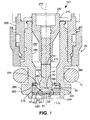
- FIG. 1 shows a sectional view of a first embodiment of a fuel injector 100 having a body 20 and a needle 140.
- the body 20 has an upstream or inlet end 210 and a downstream or outlet end 220.
- the body 20 includes an armature 240.
- the needle 140 is connected to the armature 240.
- An electromagnetic coil (not shown) located within the body 20 is selectively energised and de-energised to reciprocate the armature 240 and the needle 140 within the body 20.
- the body 20 further includes a body shell 250 which is constructed from ferromagnetic material and which forms part of a magnetic circuit which operates the magnetic coil.
- the body shell 250 partially surrounds a valve body 260 which includes a valve body chamber 262.
- the valve body chamber 262 extends through a central longitudinal portion of the body 20 along a longitudinal axis 270 extending therethrough and is formed by an interior valve body wall 264.
- a needle guide 280 having a central needle guide opening 282 and a plurality of radially spaced fuel flow openings 284 is located within the valve body chamber 262 proximate to the downstream end 220 of the body 20.
- the needle guide 280 assists in maintaining reciprocation of the needle 140 along the longitudinal axis 270.
- An o-ring 12 is located around the outer circumference of the valve body 260 to seat the injector 100 in an internal combustion engine (not shown).
- Valve seat 30 is located within the valve body chamber 262 proximate to the outlet end 220 between the needle guide 280 and the discharge end 220.
- the valve seat 30 includes a passage or valve seat orifice 320 which extends generally along the longitudinal axis 270 of the body 20 and is formed by a generally cylindrical wall. Preferably a centre 321 of the orifice 320 is on the longitudinal axis 270.
- the valve seat 30 also includes a bevelled sealing surface 330 which surrounds the orifice 320 and tapers radially downward and inward toward the orifice 320 such that the sealing surface 330 is oblique to the longitudinal axis 270.
- an o-ring can seal the interface between the valve seat 30 and the valve body 260. Although this is a preferred method of sealing the interface, those skilled in the art will also recognise that the o-ring may be omitted, and a hermetic weld (not shown) can be used to seal the interface.
- the needle 140 is reciprocally located within the valve body chamber 262 generally along the longitudinal axis 270 of the body 20. The needle 140 is reciprocable between a first, or open, position wherein the needle 140 is displaced from the valve seat 30, allowing pressurised fuel to flow downstream past the needle 140, and a second, or closed, position wherein the needle 140 is biased against the valve seat 30 (as shown in Figs.
- the needle 140 reciprocates between the second, open, position and the first, closed, position along the longitudinal axis 270 of the body 20 in response to energisation and de-energisation, respectively, of the electromagnetic coil.
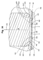
- the needle 140 includes a generally spherical tip 442 which includes a generally planar end face 144.
- the end face 144 need not be planar.
- the end face 144 is preferably generally perpendicular to the longitudinal axis 270. In both the open and closed position, the end face 144 is located upstream of the valve seat orifice 270.
- the spherical tip 442 matches the bevelled seat surface 330 of the valve seat 130 when the needle 140 is in a closed position, as shown in Fig. 1, such that a valve contact face 422 of the spherical tip 442 engages the bevelled valve seat surface 330, forming a generally line contact seal between the spherical tip 442 and the bevelled seat surface 320.
- a metering orifice 50 is located at a downstream location of the body 20, approximate to, but spaced from, the end face 144.
- the end face 144, the interior face 510 of the metering orifice 50 and the valve seat orifice 320 between the downstream side of the needle contact face 422 and the metering orifice 50 form the sac 160.
- the metering orifice 50 includes at least one, and preferably several, metering openings 530 which are radially spaced from the longitudinal axis 270 of the body 20.
- the top of the metering orifice 50 and the end face 144 are spaced from each other by a gap of between approximately 50 microns and 250 microns, more preferably between 100 microns and 250 microns in embodiments such as shown in Figs 1, 1A.
- Such spacing has been found to provide particularly advantageous operation, and is believed to represent a compromise between the need for a small sac volume 160 and the need for a relatively unimpeded fluid flow when the needle is in the second, open, position.
- valve contact face 422 When the needle 140 is in an open position, the valve contact face 422 is raised above and separated from the bevelled seat surface 330, forming an annular opening therebetween, allowing pressurised fuel to flow therethrough and through the openings 530 in the metering orifice 50 to a combustion chamber (not shown) for combustion.
- a combustion chamber (not shown) for combustion.
- the needle 140 includes a first portion 410 which has a first cross-sectional area A1 and a second portion 420 which has a second cross-sectional area A2.
- the second portion 420 includes generally spherical contact face 422 which is sized to sealingly engage the bevelled valve sealing surface 330 when the needle 40 is in the closed position to provide a generally line contact therebetween.
- a rounded surface 424 shown in enlarged Fig. 1A, connects the contact face 422 with a planar end face 144 located at a downstream tip of the needle 140.
- the end face 144 is preferably generally perpendicular to the longitudinal axis 270 of the body 20.
- both the first and second cross-sectional areas A1, A2 are circular, although those skilled in the art will recognise that the first and second cross-sectional areas A1, A2 can be other shapes as well.
- This configuration reduces the mass of the needle 140 while retaining a relatively large sealing diameter of the valve contact face 422 so as to provide a relatively generous sealing area of the needle 140 for engagement of the valve contact face 422 when the needle 140 is in the closed position.
- the increased cross-sectional area A2 of the needle 140 acts as a larger bearing surface during operation of the needle 140, thereby improving the wear resistance of the internal surface of the central needle guide opening 282.
- the improved wear resistance of the internal surface of the central needle guide opening 282 is due to reduced loading compared to that of a conventional base valve guide diameter which was used with prior art needles of a generally constant cross-sectional area.
- a typical prior art needle will have a substantially continuous cylindrically shaped shaft which terminates at an end portion wherein the cross-sectional area at the upper portion of the needle may be twice as much as the cross-sectional area A2 of the needle 140 shown in Fig. 1.
- a drawback to the larger cross-sectional area A2 is that a larger sealing diameter between the valve seat 30 and the needle 140 is required, forming a larger sac 60. This is overcome in certain embodiments of the present invention by reducing the spacing between the metering orifice 50 and the end face 144.
- the metering orifice 50 is located within the valve body chamber 262 and is connected to the body 20, downstream of the valve seat 30.
- the metering orifice 50 has an interior face 510 facing the valve seat 30 and the needle 140, and an exterior face 520 facing the combustion chamber (not shown).
- a plane of the metering orifice 50 is generally parallel to the plane of the planar end face 144.
- a virtual extension 340 of the valve seat 30 surface can be projected onto the metering orifice 50 so as to intercept the interior face 510 of the metering orifice 50 at a locus "A" shown in Fig. 1A.
- the metering orifice 50 has one or more metering openings 530, preferably radially spaced from the longitudinal axis 270.
- the metering orifice 50 includes between four and twelve metering openings 530 which are symmetrically spaced around the longitudinal axis 270. More preferably, the metering orifice 50 includes eight metering openings 530 as shown in Fig. 4.
- each metering opening 530 is generally circular and is approximately 200 microns in diameter.
- a distance between adjacent metering openings 530 is at least two and a half times as great as a diameter of the metering openings 530, although those skilled in the art will recognise that the distance between adjacent metering openings 530 can be more, or preferably less than that amount.
- An advantage to the larger cross-sectional area A2 of the needle 140 is that the interior face 510 has a larger surface area which can contain a relatively large number of metering openings 530, and yet maintain a desired separation distance between adjacent metering openings 530.
- the metering openings 530 each have a longitudinal opening axis 532 which extends generally oblique to the longitudinal axis 270 of the body 20, preferably downward and outward from the longitudinal axis 270.
- the longitudinal opening axes 532 can extend at other angles relative to the longitudinal axis 270.
- the metering openings 530 are sufficiently far from the longitudinal axis 270 such that a virtual circle formed by the virtual extension 340 of the valve seat 30 surface onto the interior face 510 of the metering orifice 50 at "A" has a smaller diameter than a virtual circle 534 drawn around an outer perimeter of the metering openings 530.
- the end face 144 extends proximate to the interior face 510 of the metering orifice 50, but allows a gap therebetween.
- the gap is between approximately 50 microns and 250 microns, and more preferably, approximately 100 and 250 microns in embodiments such as shown in Figs 1, 1A, although those skilled in the art will recognise that the gap can be other sizes as well.
- the operation of the injector 100 is as follows. Pressurised fuel flow into the injector 100 is provided by a fuel pump (not shown). The pressurised fuel enters the injector 100 and passes through a fuel filter (not shown) to the armature 240, and to the valve body chamber 262. The fuel flows through the valve body chamber 262, the fuel flow openings 284 in the guide 280 to the interface between the valve contact face 422 and the valve sealing surface 330. In the closed position (shown in Figs. 1, 1A), the needle 140 is biased against the valve seat 30 so that the valve contact face 422 sealingly engages the valve sealing surface 330, preventing flow of fuel through the metering orifice 50.
- a solenoid or other actuating device reciprocates the needle 140 to an open position, removing the valve contact face 422 of the needle 140 from the sealing surface 330 of the valve seat 30 and forming a generally annular channel. Movement of the valve contact face 422 of the needle 140 from the sealing surface 330 of the valve seat 30 also enlarges the volume of the sac 160. Pressurised fuel within the valve body chamber 262 flows past the generally annular channel formed by the needle 140 and the valve seat 30, and into the sac 160 where the fuel impacts on the interior face 510 of the metering orifice 50. The end of the channel and the metering orifice 50 are relatively close together to maintain fuel flow velocity. Since, as shown in Fig. 1A, the relative angle between the sealing surface 330 and the interior face 510 of the metering orifice is relatively slight, the fuel flow is only slightly affected and the fuel maintains a relatively high velocity without generating unwanted turbulence.
- the fuel then flows across the interior face 510 of the metering orifice 50 generally transverse to the fuel metering openings 530.
- the fuel turns into the fuel metering openings 530 where the fuel is atomised as it passes through the fuel metering openings 530 to the combustion chamber (not shown) for combustion, allowing for better combustion within the combustion chamber.
- the solenoid or other actuating device disengages, allowing the spring (not shown) to bias the needle 140 to the closed position, closing the generally annular channel and seating the valve contact face 422 of the needle 140 onto the sealing surface 330 of the valve seat 30.
- the volume or sac 160 When the needle 140 is in a closed position, cutting off the flow of metered fuel, the volume or sac 160 is re-formed between the end face 144, the metering orifice 50, and the sides of the central opening 320.
- the sac 160 tends to retain a volume of fuel in the sac which vaporises and causes rich/lean shifts and hot start issues which are undesirable. By reducing the gap between end surface 144 and orifice 50, these effects may be reduced by the attendant reduction in sac volume.
- a second embodiment of the present invention is a fuel injector 10 for use in a fuel injection system of an internal combustion engine.
- the fuel injector 10 differs from the fuel injector 100 of Figs 1, 1A in the characteristics of needle 40 and sac or volume 60.
- the needle 40 has a projection 428.
- the injector 10 also includes a volume or sac 60.
- the needle 40 is reciprocable between a first, or open, position wherein the needle 40 is displaced from the valve seat 30 (as shown in Fig. 3), allowing pressurised fuel to flow downstream past the needle 40, and a second, or closed, position wherein the needle 40 is biased against the valve seat 30 (as shown in Figs. 2, 2A) by a biasing element (not shown), preferably a spring, precluding fuel flow past the needle 40.
- the needle 40 includes a planar end face 426 located at a downstream tip of the needle 40.
- the end face 426 is preferably generally perpendicular to the longitudinal axis 270 of the body 20.
- a projection 428 extends from the end face 426 toward the discharge end 220 of the body 20.
- the projection 428 is generally a circular cylinder in shape and has a mid-point on the longitudinal axis 270 of the body 20, although those skilled in the art will recognise that the projection 428 can be other shapes as well.
- the projection 428 includes a generally planar end surface 429 which is preferably generally perpendicular to the longitudinal axis 270.
- the projection 428 is located inward of the interface between the rounded surface 424 and the end face 426, forming the end face 426 in a generally annular shape around the projection 428.
- the projection 428 encompasses approximately between 50% and 75% of the surface of the end face 426.
- the needle 40 is reciprocable between the closed position (shown in Figs. 2, 2A) and the open position (shown in Fig. 3).
- a generally annular channel 430 is formed between the valve contact face 422 and the valve sealing surface 330.
- the metering openings 530 are sufficiently far from the longitudinal axis 270 such that a virtual circle formed by the virtual extension 340 of the valve seat 30 onto the interior face 510 of the metering orifice 50 at "A" has a smaller diameter than a virtual circle 534 drawn around an outer perimeter of the metering openings 530.
- the outer perimeter of the projection 428 lies within the virtual circle 534 of the metering openings 530, although those skilled in the art will recognise that the outer perimeter of the projection 428 can lie partially or totally outside of the virtual circle 534 of the orifice openings 530 as well.
- the end face 426, the interior face 510 of the metering orifice 50 and the valve seat orifice 320 between the downstream side of the needle contact face 422 and the metering orifice 50 form the sac 60.
- the projection 428 extends from the end face 426 into the sac 60, reducing the volume of the sac 60.
- the projection 428 reduces the volume of the sac 60 between approximately 25% and 75% as compared to a similar needle without the projection 428. Still referring to Figs.
- the end face 42 when the needle 40 is in the closed position, the end face 42 extends proximate to the interior face 510 of the metering orifice 50, but allows a gap therebetween.
- the gap is between approximately 50 microns and 250 microns, and more preferably, approximately 50 and 100 microns in embodiments such as shown in Figs 2, 2A, although those skilled in the art will recognise that the gap can be other sizes as well.
- the projection 428 extends proximate to the interior face 510 of the metering orifice 50, but allows a minimum of a 50 micron gap therebetween. .
- Such spacing has been found to provide particularly advantageous operation, and is believed to represent a compromise between the need for a small sac volume 60 and the need for a relatively unimpeded fluid flow when the needle is in the second, open, position.
- the operation of the injector 10 is as follows. Pressurised fuel flow into the injector 10 is provided by a fuel pump (not shown). The pressurised fuel enters the injector 10 and passes through a fuel filter (not shown) to the armature 240, and to the valve body chamber 262. The fuel flows through the valve body chamber 262, the fuel flow openings 284 in the guide 280 to the interface between the valve contact face 422 and the valve sealing surface 330. In the closed position (shown in Figs. 2, 2A), the needle 40 is biased against the valve seat 30 so that the valve contact face 422 sealingly engages the valve sealing surface 330, preventing flow of fuel through the metering orifice 50.
- a solenoid or other actuating device reciprocates the needle 40 to an open position, removing the valve contact face 422 of the needle 40 from the sealing surface 330 of the valve seat 30 and forming the generally annular channel 430. Movement of the valve contact face 422 of the needle 40 from the sealing surface 330 of the valve seat 30 also enlarges the volume of the sac 60. Pressurised fuel within the valve body chamber 262 flows past the generally annular channel 430 formed by the needle 40 and the valve seat 30, and into the sac 60 where the fuel impacts on the interior face 510 of the metering orifice 50. The end of the channel 430 and the metering orifice 50 are relatively close together to maintain fuel flow velocity.
- the fuel then flows across the interior face 510 of the metering orifice 50 generally transverse to the fuel metering openings 530.
- the fuel turns into the fuel metering openings 530 where the fuel is atomised as it passes through the fuel metering openings 530 to the combustion chamber (not shown) for combustion, allowing for better combustion within the combustion chamber.
- the solenoid or other actuating device disengages, allowing the spring (not shown) to bias the needle 40 to the closed position, closing the generally annular channel 430 and seating the valve contact face 422 of the needle 40 onto the sealing surface 330 of the valve seat 30.
- the projection 428 extends toward the end face 426, reducing the volume of the sac 60 and hence, the amount of un-metered fuel within the sac 60.
- the presence of the projection 428 allows the minimum gap between needle 40 and orifice 50 to be reduced to 50 microns, with a preferred range extending between 50 and 100 microns.
- an orifice projection 540 can extend upward from the interior face 510 of the metering orifice 50 toward the end face 426.
- the orifice projection 540 encompasses approximately between 50% and 75% of the surface area of the planar end face 426 or of the metering orifice.
- the orifice projection 540 reduces the volume of the sac 60 in a similar manner as the projection 428 as discussed above.
- the gap between orifice projection 540 and the end face 426 when the needle 40 is in a closed position is the same gap (a minimum of 50 microns) as the gap between the projection 428 and the interior face 510 of the metering orifice 50 of the embodiment of Figs. 2, 2A when the needle 40 is in the closed position.
- both the end face 426 and the interior face 510 of the metering orifice 50 can include projections such that each projection reduces the volume of the sac 60 while leaving a gap of preferably a minimum of 50 microns between the projections when the needle 40 is in the closed position.
- a preferred range for the size of the gap is 50-100 microns.
- the amount of un-metered fuel which is released during low manifold pressure, high injector tip temperature operating conditions will be reduced. Additionally, the reduction in un-metered fuel in the sac 60 will provide improved entry conditions to the metering orifice 50, resulting in improved spray atomisation of the fuel through the fuel metering openings 530 and into the combustion chamber (not shown). The reduced amount of un-metered fuel in the sac 60 and the improved spray atomisation of the fuel into the fuel chamber will also increase the fuel efficiency of the internal combustion engine.
- valve seat 30, the needle 40, 140 and the metering orifice 50 are each constructed from stainless steel.
- valve seat 30, the needle 40, 140 and the metering orifice 50 can be constructed of other, suitable materials.
Abstract
Description
- This invention relates to injectors, and more particularly, to fuel injectors having a sac volume that minimises residual fuel after metering. This invention also relates to injectors having improved resistance to wear of their moving parts.
- Fuel injectors are commonly employed in internal combustion engines to provide precise metering of fuel for introduction into each combustion chamber. Additionally, the fuel injector atomises the fuel during injection, breaking the fuel into a large number of very small particles, increasing the surface area of the fuel being injected, and allowing the oxidiser, typically ambient air, to more thoroughly mix with the fuel prior to combustion. The precise metering and atomisation of the fuel reduces combustion emissions and increases the fuel efficiency of the engine.
- An electro-magnetic fuel injector typically utilises a solenoid assembly to supply an actuating force to a fuel metering valve. Typically, the fuel metering valve is a plunger style needle valve which reciprocates between a closed position, where the needle is seated in a valve seat to prevent fuel from escaping through a metering orifice into the combustion chamber, and an open position, where the needle is lifted from the valve seat, allowing fuel to discharge through the metering orifice for introduction into the combustion chamber.
- Typically, a volumetric chamber or sac exists between the discharge tip of the needle and the metering orifice. Upon seating of the needle on the valve seat, a volume of fuel remains within the sac and tends to drain through openings in the metering orifice after the metered fuel has already been discharged through the metering orifice, typically during low manifold pressure, high injector tip temperature operating conditions. This discharge produces rich combustion which generates unwanted exhaust emissions and reduces the fuel efficiency of the engine. Some of the fuel, however, remains in the sac which vaporises and causes rich/lean shifts and hot start issues which are undesirable.
- It would be beneficial to develop a fuel injector in which the sac volume is minimised, reducing the amount of un-metered fuel in the sac after metering. It would also be beneficial to develop an injector which has an increased resistance to wear of its moving parts.
- The invention accordingly provides apparatus and methods as defined in the appended claims.
- In particular, according to an aspect of the present invention, an injector comprises: a body having an inlet, an outlet and a longitudinal axis extending therethrough; a valve seat located within the body and disposed proximate the outlet, the valve seat including a valve seat orifice and a sealing surface surrounding the valve seat orifice; a metering orifice connected to the body downstream of the valve seat; a needle portion including an end face at its downstream end, the end face extending generally perpendicular to the longitudinal axis, said needle being reciprocably located within the body along the longitudinal axis between a first position wherein the needle is displaced from the valve seat, allowing fluid flow past the needle, and a second position wherein the needle is biased against the valve seat, precluding fluid flow past the needle; and a volume generally defined by the metering orifice, the end face and the valve seat orifice when the needle is in the second position, wherein the metering orifice includes a plurality of metering openings; and a first virtual circle defined by a virtual extension of the valve seat onto the metering orifice has a smaller dimension than a second virtual circle defined by outer extremities of the plurality of metering openings
- The metering orifice may include a plurality of metering openings.
- A distance between adjacent metering openings may be at least two and a half times a diameter of each of the metering openings.
- Each of the plurality of metering openings may have a longitudinal opening axis extending generally oblique to the longitudinal axis of the valve body.
- Fluid flow across the metering plate may be generally transverse to each of the plurality of metering openings.
- The end face may be generally planar.
- The metering orifice may be generally planar.
- The plane of the metering orifice may be generally parallel to the plane of the end face.
- The sealing surface may be oblique to the longitudinal axis.
- The valve seat orifice may be formed by a generally cylindrical wall.
- The needle may engage the valve seat in a generally annular area of contact when the needle is in the second position.
- The needle may include a first portion having a first cross-sectional area and a second portion having a second cross-sectional area, the second cross-sectional area being larger than the first cross-sectional area, the second portion including the end face, the end face being located upstream of the valve seat orifice.
- A projection may be provided, extending from at least one of the end face and the metering orifice respectively toward the other of the end face and the metering orifice.
- When the needle is in the second position, any projection may be spaced from the other of the end face and the metering orifice, or the respective other projection, by a distance of at least 50 microns.
- Any projection may preferably encompasses approximately between 50% and 75% of a surface area of the one of the planar end face and the metering orifice.
- When the needle is in the second position, the end face may be spaced from the metering orifice by a distance of between 50 microns and 250 microns.
- When the needle is in the second position, the end face may be spaced from the metering orifice by a distance of between 50 microns and 100 microns.
- When the needle is in the second position, the end face may be spaced from the metering orifice by a distance of between 100 microns and 250 microns.
- Any projection may be located between the metering openings.
- According to a further particular aspect of the present invention, a method of operating an injector, the method comprises the steps of: providing an injector including a valve seat having a valve seat orifice, a needle having an end face, a metering orifice, and a sac volume located between the end face and the metering orifice; providing pressurised fluid to the injector; opening the injector by removing the needle from the valve seat and enlarging the sac volume, thereby allowing the pressurised fluid to flow past the needle and the valve seat and through the sac volume and the metering orifice for ejection from the injector; and closing the injector by seating the needle against the valve seat, the end face being located upstream of the metering orifice, thereby reducing the sac volume, wherein the metering orifice includes a plurality of metering openings; and in that a first virtual circle defined by a virtual extension of the valve seat onto the metering orifice has a smaller dimension than a second virtual circle defined by outer extremities of the plurality of metering openings
- After completing the step of closing the injector, a distance between the needle and the metering orifice may be between 50 microns and 250 microns; more preferably between 100 microns and 250 microns; alternatively between 50 microns and 100 microns.
- The needle may include a projection extending therefrom toward the metering orifice, the projection extending into the volume during the step of closing the injector.
- The metering orifice may include a projection extending therefrom toward the needle, the projection extending into the volume during the step of closing the injector.
- The injector may be a fuel injector. The fluid may be a fuel.
- The injector may be for use in a fuel injection system of an internal combustion engine.
- The accompanying drawings, which are incorporated herein and constitute part of this specification, illustrate the presently preferred embodiments of the invention, and, together with the general description given above and the detailed description given below, serve to explain features of the invention. Preferably, a projection extends into the sac volume during the step of closing the injector, thereby reducing the sac volume and an amount of fluid within the sac volume.
- The above, and further, objects, characteristics and advantages of the present invention will become more apparent by reference to the following description of certain embodiments, given by way of examples only, with reference to the accompanying drawings.
- In the drawings:
- Fig. 1 is a side view, in section, of a discharge end of a fuel injector according to a first embodiment of the present invention with a needle in a closed position;
- Fig. 1A is an enlarged view of the discharge end of the fuel injector of Fig. 1;
- Fig. 2 is a side view, in section, of a discharge end of a fuel injector according to a second embodiment of the present invention with a needle in a closed position;
- Fig. 2A is an enlarged view of the discharge end of the fuel injector of Fig. 2;
- Fig. 3 is a side view, in section, of the discharge end of the fuel injector according to the second embodiment of the present invention with the needle in an open position;
- Fig. 4 is a top plan view of a metering orifice which may be used in an injector of the present invention.; and
- Fig. 5 is a side view, in section, of a discharge end of a fuel injector according to a third embodiment of the present invention.
-
- Details of the operation of a
fuel injector 10; 100 in relation to the operation of an internal combustion engine (not shown) are well known and will not be described in detail herein, except as the operation relates to the present invention. Although the present invention is generally directed to injector valves for internal combustion engines, those skilled in the art will recognise from the present disclosure that the present invention can be adapted for other applications in which precise metering of fluids is desired or required. - The words "inwardly" and "outwardly" refer to directions towards and away from, respectively, the longitudinal axis of each embodiment of the injector in accordance with the present invention, and designated parts thereof. The words "upstream" and "downstream" designate flow directions in the drawings to which reference is made. The upstream side is toward the top of each drawing and the downstream side is toward the bottom of each drawing.
- In the drawings, like numerals are used to indicate like elements throughout. Fig. 1 shows a sectional view of a first embodiment of a
fuel injector 100 having abody 20 and aneedle 140. - The
body 20 has an upstream orinlet end 210 and a downstream oroutlet end 220. Thebody 20 includes anarmature 240. Theneedle 140 is connected to thearmature 240. An electromagnetic coil (not shown) located within thebody 20 is selectively energised and de-energised to reciprocate thearmature 240 and theneedle 140 within thebody 20. Thebody 20 further includes abody shell 250 which is constructed from ferromagnetic material and which forms part of a magnetic circuit which operates the magnetic coil. Thebody shell 250 partially surrounds avalve body 260 which includes avalve body chamber 262. Thevalve body chamber 262 extends through a central longitudinal portion of thebody 20 along alongitudinal axis 270 extending therethrough and is formed by an interiorvalve body wall 264. Aneedle guide 280 having a central needle guide opening 282 and a plurality of radially spacedfuel flow openings 284 is located within thevalve body chamber 262 proximate to thedownstream end 220 of thebody 20. Theneedle guide 280 assists in maintaining reciprocation of theneedle 140 along thelongitudinal axis 270. Anovermould 290 constructed of a dielectric material, preferably a plastic or other suitable material, encompasses thebody shell 250. An o-ring 12 is located around the outer circumference of thevalve body 260 to seat theinjector 100 in an internal combustion engine (not shown). -
Valve seat 30 is located within thevalve body chamber 262 proximate to theoutlet end 220 between theneedle guide 280 and thedischarge end 220. Thevalve seat 30 includes a passage orvalve seat orifice 320 which extends generally along thelongitudinal axis 270 of thebody 20 and is formed by a generally cylindrical wall. Preferably acentre 321 of theorifice 320 is on thelongitudinal axis 270. Thevalve seat 30 also includes a bevelled sealingsurface 330 which surrounds theorifice 320 and tapers radially downward and inward toward theorifice 320 such that the sealingsurface 330 is oblique to thelongitudinal axis 270. - Although not shown, those skilled in the art will recognise that an o-ring can seal the interface between the
valve seat 30 and thevalve body 260. Although this is a preferred method of sealing the interface, those skilled in the art will also recognise that the o-ring may be omitted, and a hermetic weld (not shown) can be used to seal the interface. Theneedle 140 is reciprocally located within thevalve body chamber 262 generally along thelongitudinal axis 270 of thebody 20. Theneedle 140 is reciprocable between a first, or open, position wherein theneedle 140 is displaced from thevalve seat 30, allowing pressurised fuel to flow downstream past theneedle 140, and a second, or closed, position wherein theneedle 140 is biased against the valve seat 30 (as shown in Figs. 1, 1A) by a biasing element (not shown), preferably a spring, precluding fuel flow past theneedle 140. Theneedle 140 reciprocates between the second, open, position and the first, closed, position along thelongitudinal axis 270 of thebody 20 in response to energisation and de-energisation, respectively, of the electromagnetic coil. Theneedle 140 includes a generallyspherical tip 442 which includes a generallyplanar end face 144. However, those skilled in the art will recognise that theend face 144 need not be planar. Theend face 144 is preferably generally perpendicular to thelongitudinal axis 270. In both the open and closed position, theend face 144 is located upstream of thevalve seat orifice 270. Thespherical tip 442 matches thebevelled seat surface 330 of the valve seat 130 when theneedle 140 is in a closed position, as shown in Fig. 1, such that avalve contact face 422 of thespherical tip 442 engages the bevelledvalve seat surface 330, forming a generally line contact seal between thespherical tip 442 and thebevelled seat surface 320. Ametering orifice 50 is located at a downstream location of thebody 20, approximate to, but spaced from, theend face 144. - With the
needle 140 in a closed position, as shown in Figs. 1, 1A, theend face 144, theinterior face 510 of themetering orifice 50 and thevalve seat orifice 320 between the downstream side of theneedle contact face 422 and themetering orifice 50 form thesac 160. - The
metering orifice 50 includes at least one, and preferably several,metering openings 530 which are radially spaced from thelongitudinal axis 270 of thebody 20. Preferably, in the closed position, the top of themetering orifice 50 and theend face 144 are spaced from each other by a gap of between approximately 50 microns and 250 microns, more preferably between 100 microns and 250 microns in embodiments such as shown in Figs 1, 1A. Such spacing has been found to provide particularly advantageous operation, and is believed to represent a compromise between the need for asmall sac volume 160 and the need for a relatively unimpeded fluid flow when the needle is in the second, open, position. - When the
needle 140 is in an open position, thevalve contact face 422 is raised above and separated from the bevelledseat surface 330, forming an annular opening therebetween, allowing pressurised fuel to flow therethrough and through theopenings 530 in themetering orifice 50 to a combustion chamber (not shown) for combustion. Upon closing of theneedle 140 so that thevalve contact face 422 engages thebevelled seat surface 330, the flow of fuel through theinjector 100 is cut off. - Still referring to Figs. 1, 1A, the
needle 140 includes afirst portion 410 which has a first cross-sectional area A1 and asecond portion 420 which has a second cross-sectional area A2. Thesecond portion 420 includes generallyspherical contact face 422 which is sized to sealingly engage the bevelledvalve sealing surface 330 when theneedle 40 is in the closed position to provide a generally line contact therebetween. Arounded surface 424, shown in enlarged Fig. 1A, connects thecontact face 422 with aplanar end face 144 located at a downstream tip of theneedle 140. Theend face 144 is preferably generally perpendicular to thelongitudinal axis 270 of thebody 20. - Preferably, both the first and second cross-sectional areas A1, A2 are circular, although those skilled in the art will recognise that the first and second cross-sectional areas A1, A2 can be other shapes as well. This configuration reduces the mass of the
needle 140 while retaining a relatively large sealing diameter of thevalve contact face 422 so as to provide a relatively generous sealing area of theneedle 140 for engagement of thevalve contact face 422 when theneedle 140 is in the closed position. The increased cross-sectional area A2 of theneedle 140 acts as a larger bearing surface during operation of theneedle 140, thereby improving the wear resistance of the internal surface of the central needle guide opening 282. The improved wear resistance of the internal surface of the central needle guide opening 282 is due to reduced loading compared to that of a conventional base valve guide diameter which was used with prior art needles of a generally constant cross-sectional area. For example, a typical prior art needle will have a substantially continuous cylindrically shaped shaft which terminates at an end portion wherein the cross-sectional area at the upper portion of the needle may be twice as much as the cross-sectional area A2 of theneedle 140 shown in Fig. 1. A drawback to the larger cross-sectional area A2 is that a larger sealing diameter between thevalve seat 30 and theneedle 140 is required, forming alarger sac 60. This is overcome in certain embodiments of the present invention by reducing the spacing between themetering orifice 50 and theend face 144. - The
metering orifice 50 is located within thevalve body chamber 262 and is connected to thebody 20, downstream of thevalve seat 30. Themetering orifice 50 has aninterior face 510 facing thevalve seat 30 and theneedle 140, and anexterior face 520 facing the combustion chamber (not shown). A plane of themetering orifice 50 is generally parallel to the plane of theplanar end face 144. Avirtual extension 340 of thevalve seat 30 surface can be projected onto themetering orifice 50 so as to intercept theinterior face 510 of themetering orifice 50 at a locus "A" shown in Fig. 1A. - Still referring to Fig. 1A, the
metering orifice 50 has one ormore metering openings 530, preferably radially spaced from thelongitudinal axis 270. Preferably, themetering orifice 50 includes between four and twelvemetering openings 530 which are symmetrically spaced around thelongitudinal axis 270. More preferably, themetering orifice 50 includes eightmetering openings 530 as shown in Fig. 4. Preferably, eachmetering opening 530 is generally circular and is approximately 200 microns in diameter. Preferably, a distance betweenadjacent metering openings 530 is at least two and a half times as great as a diameter of themetering openings 530, although those skilled in the art will recognise that the distance betweenadjacent metering openings 530 can be more, or preferably less than that amount. An advantage to the larger cross-sectional area A2 of theneedle 140 is that theinterior face 510 has a larger surface area which can contain a relatively large number ofmetering openings 530, and yet maintain a desired separation distance betweenadjacent metering openings 530. - Preferably, the
metering openings 530 each have alongitudinal opening axis 532 which extends generally oblique to thelongitudinal axis 270 of thebody 20, preferably downward and outward from thelongitudinal axis 270. However, those skilled in the art will recognise that the longitudinal opening axes 532 can extend at other angles relative to thelongitudinal axis 270. As illustrated in Fig. 4, themetering openings 530 are sufficiently far from thelongitudinal axis 270 such that a virtual circle formed by thevirtual extension 340 of thevalve seat 30 surface onto theinterior face 510 of themetering orifice 50 at "A" has a smaller diameter than avirtual circle 534 drawn around an outer perimeter of themetering openings 530. This ensures that the flow of fuel between thevalve seat 30 and theneedle 140 when theneedle 140 is in the open position directs the fuel onto themetering orifice 50 to provide a transverse flow of the fuel across themetering orifice 50 to themetering openings 530 prior to the fuel entering themetering openings 530. - When the
needle 140 is in the closed position, theend face 144 extends proximate to theinterior face 510 of themetering orifice 50, but allows a gap therebetween. Preferably, the gap is between approximately 50 microns and 250 microns, and more preferably, approximately 100 and 250 microns in embodiments such as shown in Figs 1, 1A, although those skilled in the art will recognise that the gap can be other sizes as well. - The operation of the
injector 100 is as follows. Pressurised fuel flow into theinjector 100 is provided by a fuel pump (not shown). The pressurised fuel enters theinjector 100 and passes through a fuel filter (not shown) to thearmature 240, and to thevalve body chamber 262. The fuel flows through thevalve body chamber 262, thefuel flow openings 284 in theguide 280 to the interface between thevalve contact face 422 and thevalve sealing surface 330. In the closed position (shown in Figs. 1, 1A), theneedle 140 is biased against thevalve seat 30 so that thevalve contact face 422 sealingly engages thevalve sealing surface 330, preventing flow of fuel through themetering orifice 50. - In the open position, a solenoid or other actuating device, (not shown) reciprocates the
needle 140 to an open position, removing thevalve contact face 422 of theneedle 140 from the sealingsurface 330 of thevalve seat 30 and forming a generally annular channel. Movement of thevalve contact face 422 of theneedle 140 from the sealingsurface 330 of thevalve seat 30 also enlarges the volume of thesac 160. Pressurised fuel within thevalve body chamber 262 flows past the generally annular channel formed by theneedle 140 and thevalve seat 30, and into thesac 160 where the fuel impacts on theinterior face 510 of themetering orifice 50. The end of the channel and themetering orifice 50 are relatively close together to maintain fuel flow velocity. Since, as shown in Fig. 1A, the relative angle between the sealingsurface 330 and theinterior face 510 of the metering orifice is relatively slight, the fuel flow is only slightly affected and the fuel maintains a relatively high velocity without generating unwanted turbulence. - The fuel then flows across the
interior face 510 of themetering orifice 50 generally transverse to thefuel metering openings 530. The fuel turns into thefuel metering openings 530 where the fuel is atomised as it passes through thefuel metering openings 530 to the combustion chamber (not shown) for combustion, allowing for better combustion within the combustion chamber. - When a pre-determined amount of fuel has been injected into the combustion chamber, the solenoid or other actuating device disengages, allowing the spring (not shown) to bias the
needle 140 to the closed position, closing the generally annular channel and seating thevalve contact face 422 of theneedle 140 onto the sealingsurface 330 of thevalve seat 30. - When the
needle 140 is in a closed position, cutting off the flow of metered fuel, the volume orsac 160 is re-formed between theend face 144, themetering orifice 50, and the sides of thecentral opening 320. Thesac 160 tends to retain a volume of fuel in the sac which vaporises and causes rich/lean shifts and hot start issues which are undesirable. By reducing the gap betweenend surface 144 andorifice 50, these effects may be reduced by the attendant reduction in sac volume. - A second embodiment of the present invention, shown in Figs. 2-4, is a
fuel injector 10 for use in a fuel injection system of an internal combustion engine. Features corresponding to those of Figs 1, 1A carry corresponding reference numerals. Thefuel injector 10 differs from thefuel injector 100 of Figs 1, 1A in the characteristics ofneedle 40 and sac orvolume 60. Notably, according to this second embodiment, theneedle 40 has aprojection 428. Theinjector 10 also includes a volume orsac 60. - The
needle 40 is reciprocable between a first, or open, position wherein theneedle 40 is displaced from the valve seat 30 (as shown in Fig. 3), allowing pressurised fuel to flow downstream past theneedle 40, and a second, or closed, position wherein theneedle 40 is biased against the valve seat 30 (as shown in Figs. 2, 2A) by a biasing element (not shown), preferably a spring, precluding fuel flow past theneedle 40. - Referring now to Figs. 2, 2A, the
needle 40 includes aplanar end face 426 located at a downstream tip of theneedle 40. Theend face 426 is preferably generally perpendicular to thelongitudinal axis 270 of thebody 20. Aprojection 428 extends from theend face 426 toward thedischarge end 220 of thebody 20. Preferably, theprojection 428 is generally a circular cylinder in shape and has a mid-point on thelongitudinal axis 270 of thebody 20, although those skilled in the art will recognise that theprojection 428 can be other shapes as well. Theprojection 428 includes a generallyplanar end surface 429 which is preferably generally perpendicular to thelongitudinal axis 270. Theprojection 428 is located inward of the interface between therounded surface 424 and theend face 426, forming theend face 426 in a generally annular shape around theprojection 428. Preferably, theprojection 428 encompasses approximately between 50% and 75% of the surface of theend face 426. - The
needle 40 is reciprocable between the closed position (shown in Figs. 2, 2A) and the open position (shown in Fig. 3). When theneedle 40 is in the open position, a generallyannular channel 430 is formed between thevalve contact face 422 and thevalve sealing surface 330. - As illustrated in Fig. 4, the
metering openings 530 are sufficiently far from thelongitudinal axis 270 such that a virtual circle formed by thevirtual extension 340 of thevalve seat 30 onto theinterior face 510 of themetering orifice 50 at "A" has a smaller diameter than avirtual circle 534 drawn around an outer perimeter of themetering openings 530. Preferably, the outer perimeter of theprojection 428 lies within thevirtual circle 534 of themetering openings 530, although those skilled in the art will recognise that the outer perimeter of theprojection 428 can lie partially or totally outside of thevirtual circle 534 of theorifice openings 530 as well. - With the
needle 40 in a closed position, as shown in Figs. 2, 2A, theend face 426, theinterior face 510 of themetering orifice 50 and thevalve seat orifice 320 between the downstream side of theneedle contact face 422 and themetering orifice 50 form thesac 60. Theprojection 428 extends from theend face 426 into thesac 60, reducing the volume of thesac 60. Preferably, theprojection 428 reduces the volume of thesac 60 between approximately 25% and 75% as compared to a similar needle without theprojection 428. Still referring to Figs. 2, 2A, when theneedle 40 is in the closed position, the end face 42 extends proximate to theinterior face 510 of themetering orifice 50, but allows a gap therebetween. Preferably, the gap is between approximately 50 microns and 250 microns, and more preferably, approximately 50 and 100 microns in embodiments such as shown in Figs 2, 2A, although those skilled in the art will recognise that the gap can be other sizes as well. Further, theprojection 428 extends proximate to theinterior face 510 of themetering orifice 50, but allows a minimum of a 50 micron gap therebetween. . Such spacing has been found to provide particularly advantageous operation, and is believed to represent a compromise between the need for asmall sac volume 60 and the need for a relatively unimpeded fluid flow when the needle is in the second, open, position. - The operation of the
injector 10 is as follows. Pressurised fuel flow into theinjector 10 is provided by a fuel pump (not shown). The pressurised fuel enters theinjector 10 and passes through a fuel filter (not shown) to thearmature 240, and to thevalve body chamber 262. The fuel flows through thevalve body chamber 262, thefuel flow openings 284 in theguide 280 to the interface between thevalve contact face 422 and thevalve sealing surface 330. In the closed position (shown in Figs. 2, 2A), theneedle 40 is biased against thevalve seat 30 so that thevalve contact face 422 sealingly engages thevalve sealing surface 330, preventing flow of fuel through themetering orifice 50. - In the open position (shown in Fig. 3), a solenoid or other actuating device, (not shown) reciprocates the
needle 40 to an open position, removing thevalve contact face 422 of theneedle 40 from the sealingsurface 330 of thevalve seat 30 and forming the generallyannular channel 430. Movement of thevalve contact face 422 of theneedle 40 from the sealingsurface 330 of thevalve seat 30 also enlarges the volume of thesac 60. Pressurised fuel within thevalve body chamber 262 flows past the generallyannular channel 430 formed by theneedle 40 and thevalve seat 30, and into thesac 60 where the fuel impacts on theinterior face 510 of themetering orifice 50. The end of thechannel 430 and themetering orifice 50 are relatively close together to maintain fuel flow velocity. Since, as shown in Fig. 2A, the relative angle between the sealingsurface 330 and theinterior face 510 of the metering orifice is relatively slight, the fuel flow is only slightly affected and the fuel maintains a relatively high velocity without generating unwanted turbulence. - The fuel then flows across the
interior face 510 of themetering orifice 50 generally transverse to thefuel metering openings 530. The fuel turns into thefuel metering openings 530 where the fuel is atomised as it passes through thefuel metering openings 530 to the combustion chamber (not shown) for combustion, allowing for better combustion within the combustion chamber. - When a pre-determined amount of fuel has been injected into the combustion chamber, the solenoid or other actuating device disengages, allowing the spring (not shown) to bias the
needle 40 to the closed position, closing the generallyannular channel 430 and seating thevalve contact face 422 of theneedle 40 onto the sealingsurface 330 of thevalve seat 30. Theprojection 428 extends toward theend face 426, reducing the volume of thesac 60 and hence, the amount of un-metered fuel within thesac 60. Advantageously, the presence of theprojection 428 allows the minimum gap betweenneedle 40 andorifice 50 to be reduced to 50 microns, with a preferred range extending between 50 and 100 microns. - In a third embodiment, shown in Fig. 5, instead of a
projection 428 extending downward from theend face 426 into thesac 60, anorifice projection 540 can extend upward from theinterior face 510 of themetering orifice 50 toward theend face 426. Preferably, theorifice projection 540 encompasses approximately between 50% and 75% of the surface area of theplanar end face 426 or of the metering orifice. Theorifice projection 540 reduces the volume of thesac 60 in a similar manner as theprojection 428 as discussed above. Preferably, the gap betweenorifice projection 540 and theend face 426 when theneedle 40 is in a closed position is the same gap (a minimum of 50 microns) as the gap between theprojection 428 and theinterior face 510 of themetering orifice 50 of the embodiment of Figs. 2, 2A when theneedle 40 is in the closed position. - Alternatively, although not shown, those skilled in the art will recognise that both the
end face 426 and theinterior face 510 of themetering orifice 50 can include projections such that each projection reduces the volume of thesac 60 while leaving a gap of preferably a minimum of 50 microns between the projections when theneedle 40 is in the closed position. A preferred range for the size of the gap is 50-100 microns. Such spacing has been found to provide particularly advantageous operation, and is believed to represent a compromise between the need for a small sac volume and the need for a relatively unimpeded fluid flow when the needle is in the second, open, position. - By reducing the volume of the
sac 60 as described, the amount of un-metered fuel which is released during low manifold pressure, high injector tip temperature operating conditions will be reduced. Additionally, the reduction in un-metered fuel in thesac 60 will provide improved entry conditions to themetering orifice 50, resulting in improved spray atomisation of the fuel through thefuel metering openings 530 and into the combustion chamber (not shown). The reduced amount of un-metered fuel in thesac 60 and the improved spray atomisation of the fuel into the fuel chamber will also increase the fuel efficiency of the internal combustion engine. - Preferably, in each of the embodiments described above, the
valve seat 30, theneedle metering orifice 50 are each constructed from stainless steel. However, those skilled in the art will recognise that thevalve seat 30, theneedle metering orifice 50 can be constructed of other, suitable materials. - It will be appreciated by those skilled in the art that changes could be made to the embodiments described above without departing from the broad inventive concept thereof. It is understood, therefore, that this invention is not limited to the particular embodiments disclosed, but it is intended to cover modifications within the scope of the appended claims.
- The following clauses recite certain preferred features of embodiments of the present invention, and they form part of the description, as confirmed in the Decision of the Legal Board of Appeal J15/88 dated 20 July 1989.
- (i) An injector comprising: a body having an inlet, an outlet and a longitudinal axis extending therethrough; a valve seat located within the body and disposed proximate the outlet, the valve seat including a valve seat orifice and a sealing surface surrounding the valve seat orifice; a metering orifice connected to the body downstream of the valve seat; a needle portion including an end face at its downstream end, the end face extending generally perpendicular to the longitudinal axis, said needle being reciprocably located within the body along the longitudinal axis between a first position wherein the needle is displaced from the valve seat, allowing fluid flow past the needle, and a second position wherein the needle is biased against the valve seat, precluding fluid flow past the needle; and a volume generally defined by the metering orifice, the end face and the valve seat orifice when the needle is in the second position, wherein the metering orifice includes a plurality of metering openings; and a first virtual circle defined by a virtual extension of the valve seat onto the metering orifice has a smaller dimension than a second virtual circle (534) defined by outer extremities of the plurality of metering openings
- (ii) An injector comprising: a body having an inlet, an outlet and a longitudinal axis extending therethrough; a valve seat located within the body and disposed proximate the outlet, the valve seat including a valve seat orifice and a sealing surface surrounding the valve seat orifice; a metering orifice connected to the body downstream of the valve seat; a needle portion including an end face at its downstream end, the end face extending generally perpendicular to the longitudinal axis, said needle being reciprocably located within the body along the longitudinal axis between a first position wherein the needle is displaced from the valve seat, allowing fluid flow past the needle, and a second position wherein the needle is biased against the valve seat, precluding fluid flow past the needle; and a volume generally defined by the metering orifice, the end face and the valve seat orifice when the needle is in the second position, wherein the needle includes a first portion having a first cross-sectional area and a second portion having a second cross-sectional area, the second cross-sectional area being larger than the first cross-sectional area, the second portion including the end face, the end face being located upstream of the valve seat orifice.
- (iii) An injector comprising: a body having an inlet, an outlet and a longitudinal axis extending therethrough; a valve seat located within the body and disposed proximate the outlet, the valve seat including a valve seat orifice and a sealing surface surrounding the valve seat orifice; a metering orifice connected to the body downstream of the valve seat; a needle portion including an end face at its downstream end, the end face extending generally perpendicular to the longitudinal axis, said needle being reciprocably located within the body along the longitudinal axis between a first position wherein the needle is displaced from the valve seat, allowing fluid flow past the needle, and a second position wherein the needle is biased against the valve seat, precluding fluid flow past the needle; and a volume generally defined by the metering orifice, the end face and the valve seat orifice when the needle is in the second position, wherein a projection extends from at least one of the end face and the metering orifice respectively toward the other of the end face and the metering orifice.
- (iv) An injector comprising: a body having an inlet, an outlet and a longitudinal axis extending therethrough; a valve seat located within the body and disposed proximate the outlet, the valve seat including a valve seat orifice and a sealing surface surrounding the valve seat orifice; a metering orifice connected to the body downstream of the valve seat; a needle reciprocably located within the body along the longitudinal axis, between a first position wherein the needle is displaced from the valve seat, allowing fluid flow past the needle, and a second position wherein the needle is biased against the valve seat, precluding fluid flow past the needle, the needle including a first portion having a first cross-sectional area and a second portion having a second cross-sectional area, the second portion including an end face extending generally perpendicular to the longitudinal axis; and a volume generally defined by the metering orifice, the end face and the valve seat orifice when the needle is in the second position, the metering orifice then being spaced from the end face by a distance of between 50 microns and 250 microns.
- (v) The injector according to any of clauses (ii)-(iv), wherein the metering orifice includes a plurality of metering openings.
- (vi) The injector according to clause (v), wherein a distance between adjacent metering openings is at least two and a half times a diameter of each of the metering openings.
- (vii) The injector according to clause (v) or clause (vi), wherein each of the plurality of metering openings has a longitudinal opening axis extending generally oblique to the longitudinal axis of the valve body.
- (viii) The injector according to any of clauses (v)-(vii), wherein fluid flow across the metering plate is generally transverse to each of the plurality of metering openings.
- (ix) The injector according to any of clauses (v)-(viii), wherein a first virtual circle defined by a virtual extension of the valve seat onto the metering orifice has a smaller diameter than a second, concentric virtual circle defined by outer extremities of the plurality of metering openings.
- (x) The injector according to any preceding clause, wherein the end face is generally planar.
- (xi) The injector according to any preceding clause, wherein the metering orifice is generally planar.
- (xii) The injector according to clauses (x) and (xi), wherein the plane of the metering orifice is generally parallel to the plane of the end face.
- (xiii) The injector according to any preceding clause, wherein the sealing surface is oblique to the longitudinal axis.
- (xiv) The injector according to any preceding clause, wherein the valve seat orifice is formed by a generally cylindrical wall.
- (xv) The injector according to any preceding clause, wherein the needle engages the valve seat in a generally annular area of contact when the needle is in the second position.
- (xvi) The injector according to any of clauses (i), (iii), or (iv), or any clause dependent on any of clauses (i), (iii), or (iv), wherein the needle includes a first portion having a first cross-sectional area and a second portion having a second cross-sectional area, the second cross-sectional area being larger than the first cross-sectional area, the second portion including the end face, the end face being located upstream of the valve seat orifice.
- (xvii) The injector according to any of clauses (i), (ii), or (iv) or any clause dependent on any of clauses (i), (ii), or (iv), further including a projection extending from at least one of the end face and the metering orifice respectively toward the other of the end face and the metering orifice.
- (xviii) The injector according to any of clauses (i), (ii), or (iii) or any clause dependent on any of clauses (i), (ii), or (iii), wherein, when the needle is in the second position, the or each projection is spaced from the other of the end face and the metering orifice, or the respective other projection, by a distance of at least 50 microns.
- (xix) The injector according to clauses (iii) or (xvii) or any clause dependent on any of clauses (iii) or (xvii), wherein the projection encompasses approximately between 50% and 75% of a surface area of the one of the planar end face and the metering orifice.
- (xx) The injector according to any of clauses (i), (ii), or (iii) or any clause dependent on any of clauses (i), (ii), or (iii), wherein, when the needle is in the second position, the end face is spaced from the metering orifice by a distance of between 50 microns and 250 microns.
- (xxi) The injector according to any preceding clause, wherein, when the needle is in the second position, the end face is spaced from the metering orifice by a distance of between 50 microns and 100 microns.
- (xxii) The injector according to any of clauses (i) - (xx), wherein, when the needle is in the second position, the end face is spaced from the metering orifice by a distance of between 100 microns and 250 microns.
- (xxiii) The injector according to any of: clauses (i) and (xvii); or clauses (iii) and (v); or clauses (v) and (xvii); or any clause dependent on any of: clauses (i) and (xvii); or clauses (iii) and (v); or clauses (v) and (xvii), wherein the projection is located between the metering openings.
- (xxiv)A method of operating an injector, the method comprising the steps of: providing an injector including a valve seat having a valve seat orifice, a needle having an end face, a metering orifice, and a sac volume located between the end face and the metering orifice; providing pressurised fluid to the injector; opening the injector by removing the needle from the valve seat and enlarging the sac volume, thereby allowing the pressurised fluid to flow past the needle and the valve seat and through the sac volume and the metering orifice for ejection from the injector; and closing the injector by seating the needle against the valve seat, the end face being located upstream of the metering orifice, thereby reducing the sac volume, wherein the metering orifice includes a plurality of metering openings; and in that a first virtual circle defined by a virtual extension of the valve seat onto the metering orifice has a smaller dimension than a second virtual circle (534) defined by outer extremities of the plurality of metering openings
- (xxv) A method of reducing a sac volume in an injector, the injector including a valve seat having a valve seat orifice, a needle having an end face, a metering orifice, and a sac volume located between the end face and the metering orifice, the method comprising the steps of: providing such an injector; providing pressurised fluid to the injector; opening the injector by removing the needle from the valve seat and enlarging the sac volume, thereby allowing the pressurised fluid to flow past the needle and the valve seat and through the sac volume and the metering orifice for ejection from the injector; and closing the injector by seating the needle against the valve seat, the end face being located upstream of the metering orifice, wherein a projection extends into the sac volume during the step of closing the injector, thereby reducing the sac volume and an amount of fluid within the sac volume.
- (xxvi) A method of reducing a sac volume in an injector, the injector including a valve seat having a valve seat orifice, a needle having an end face, a metering orifice, and a sac volume located between the end face and the metering orifice, the method comprising the steps of: providing such an injector; providing pressurised fluid to the injector; opening the injector by removing the needle from the valve seat and enlarging the sac volume, thereby allowing the pressurised fluid to flow past the needle and the valve seat and through the sac volume and the metering orifice for ejection from the injector; and closing the injector by seating the needle against the valve seat, the end face being located upstream of the metering orifice, thereby reducing the sac volume, wherein, after completing the step of closing the injector, a distance between the needle and the metering orifice is between 50 microns and 250 microns.
- (xxvii) The method according to any of clauses (xxiv)-(xxvi), wherein, after completing the step of closing the injector, a distance between the needle and the metering orifice is between 50 microns and 250 microns.
- (xxviii) The method according to any of clauses (xxiv)-(xxvii), wherein, after completing the step of closing the injector, a distance between the needle and the metering orifice is between 100 microns and 250 microns.
- (xxix) The method according to any of clauses (xxiv)-(xxvii), wherein, after completing the step of closing the injector, a distance between the needle and the metering orifice is between 50 microns and 100 microns.
- (xxx) The method according to any of clauses (xxiv)-(xxix), wherein the needle includes a projection extending therefrom toward the metering orifice, the projection extending into the volume during the step of closing the injector.
- (xxxi) The method according to any of clauses (xxiv)-(xxx), wherein the metering orifice includes a projection extending therefrom toward the needle, the projection extending into the volume during the step of closing the injector.
- (xxxii) The method according to any of clauses (xxv) or (xxvi) or any clause dependent of any of clauses (xxv) or (xxvi), wherein the metering orifice includes a plurality of metering openings; and in that a first virtual circle defined by a virtual extension of the valve seat onto the metering orifice has a smaller dimension than a second virtual circle defined by outer extremities of the plurality of metering openings
- (xxxiii) An injector or method according to any preceding clause wherein the injector is a fuel injector and the fluid is a fuel.
- (xxxiv) An injector or method according to any preceding clause wherein the injector is for use in a fuel injection system of an internal combustion engine.
-
Claims (34)
- An injector (10; 100) comprising:characterised in that the metering orifice includes a plurality of metering openings (530); and in that a first virtual circle (340) defined by a virtual extension of the valve seat onto the metering orifice has a smaller dimension than a second virtual circle (534) defined by outer extremities of the plurality of metering openingsa body (20) having an inlet (240), an outlet (220) and a longitudinal axis (270) extending therethrough;a valve seat (30) located within the body and disposed proximate the outlet, the valve seat including a valve seat orifice (320) and a sealing surface (330) surrounding the valve seat orifice;a metering orifice (50) connected to the body downstream of the valve seat;a needle (40; 140) portion including an end face (144; 426) at its downstream end, the end face extending generally perpendicular to the longitudinal axis, said needle being reciprocably located within the body along the longitudinal axis between a first position wherein the needle is displaced from the valve seat, allowing fluid flow past the needle, and a second position wherein the needle is biased against the valve seat, precluding fluid flow past the needle; anda volume (60, 160) generally defined by the metering orifice, the end face and the valve seat orifice when the needle is in the second position,
- An injector (10; 100) comprising:characterised in that the needle includes a first portion (410) having a first cross-sectional area (A1) and a second portion (420) having a second cross-sectional area (A2), the second cross-sectional area being larger than the first cross-sectional area, the second portion including the end face, the end face being located upstream of the valve seat orifice.a body (20) having an inlet (240), an outlet (220) and a longitudinal axis (270) extending therethrough;a valve seat (30) located within the body and disposed proximate the outlet, the valve seat including a valve seat orifice (320) and a sealing surface (330) surrounding the valve seat orifice;a metering orifice (50) connected to the body downstream of the valve seat;a needle (40; 140) portion including an end face (144; 426) at its downstream end, the end face extending generally perpendicular to the longitudinal axis, said needle being reciprocably located within the body along the longitudinal axis between a first position wherein the needle is displaced from the valve seat, allowing fluid flow past the needle, and a second position wherein the needle is biased against the valve seat, precluding fluid flow past the needle; anda volume (60, 160) generally defined by the metering orifice, the end face and the valve seat orifice when the needle is in the second position,
- An injector (10; 100) comprising:characterised in that a projection (428) extends from at least one of the end face and the metering orifice respectively toward the other of the end face and the metering orifice.a body (20) having an inlet (240), an outlet (220) and a longitudinal axis (270) extending therethrough;a valve seat (30) located within the body and disposed proximate the outlet, the valve seat including a valve seat orifice (320) and a sealing surface (330) surrounding the valve seat orifice;a metering orifice (50) connected to the body downstream of the valve seat;a needle (40; 140) portion including an end face at its downstream end, the end face extending generally perpendicular to the longitudinal axis, said needle being reciprocably located within the body along the longitudinal axis between a first position wherein the needle is displaced from the valve seat, allowing fluid flow past the needle, and a second position wherein the needle is biased against the valve seat, precluding fluid flow past the needle; anda volume (60, 160) generally defined by the metering orifice, the end face and the valve seat orifice when the needle is in the second position,
- An injector (10; 100) comprising:a body (20) having an inlet (240), an outlet (220) and a longitudinal axis (270) extending therethrough;a valve seat (30) located within the body and disposed proximate the outlet, the valve seat including a valve seat orifice (320) and a sealing surface (330) surrounding the valve seat orifice;a metering orifice (50) connected to the body downstream of the valve seat;a needle (40; 140) reciprocably located within the body along the longitudinal axis, between a first position wherein the needle is displaced from the valve seat, allowing fluid flow past the needle, and a second position wherein the needle is biased against the valve seat, precluding fluid flow past the needle, the needle including a first portion having a first cross-sectional area and a second portion having a second cross-sectional area, the second portion including an end face extending generally perpendicular to the longitudinal axis; anda volume (60;160) generally defined by the metering orifice, the end face and the valve seat orifice when the needle is in the second position, the metering orifice then being spaced from the end face by a distance of between 50 microns and 250 microns.
- The injector according to any of claims 2-4, wherein the metering orifice includes a plurality of metering openings (530).
- The injector according to claim 5, wherein a distance between adjacent metering openings is at least two and a half times a diameter of each of the metering openings.
- The injector according to claim 5 or claim 6, wherein each of the plurality of metering openings has a longitudinal opening axis (532) extending generally oblique to the longitudinal axis (270) of the valve body.
- The injector according to any of claims 5-7, wherein fluid flow across the metering plate is generally transverse to each of the plurality of metering openings.
- The injector according to any of claims 5-8, wherein a first virtual circle (340) defined by a virtual extension of the valve seat onto the metering orifice has a smaller diameter than a second, concentric virtual circle (534) defined by outer extremities of the plurality of metering openings.
- The injector according to any preceding claim, wherein the end face is generally planar.
- The injector according to any preceding claim, wherein the metering orifice is generally planar.
- The injector according to claims 10 and 11, wherein the plane of the metering orifice is generally parallel to the plane of the end face.
- The injector according to any preceding claim, wherein the sealing surface is oblique to the longitudinal axis.
- The injector according to any preceding claim, wherein the valve seat orifice is formed by a generally cylindrical wall (322).
- The injector according to any preceding claim, wherein the needle engages the valve seat in a generally annular area of contact (422) when the needle is in the second position.
- The injector according to any of claims 1, 3 or 4, or any claim dependent on any of claims 1, 3 or 4, wherein the needle includes a first portion (410) having a first cross-sectional area (A1) and a second portion (420) having a second cross-sectional area (A2), the second cross-sectional area being larger than the first cross-sectional area, the second portion including the end face, the end face being located upstream of the valve seat orifice.
- The injector according to any of claims 1, 2 or 4 or any claim dependent on any of claims 1, 2 or 4, further including a projection (428) extending from at least one of the end face and the metering orifice respectively toward the other of the end face and the metering orifice.
- The injector according to any of claims 1-3 or any claim dependent on any of claims 1-3, wherein, when the needle is in the second position, the or each projection is spaced from the other of the end face and the metering orifice, or the respective other projection, by a distance of at least 50 microns.
- The injector according to claim 3 or claim 17, or any claim dependent on claim 3 or claim 17, wherein the projection encompasses approximately between 50% and 75% of a surface area of the one of the planar end face and the metering orifice.
- The injector according to any of claims 1-3 or any claim dependent on any of claims 1-3, wherein, when the needle is in the second position, the end face is spaced from the metering orifice by a distance of between 50 microns and 250 microns.
- The injector according to any preceding claim, wherein, when the needle is in the second position, the end face is spaced from the metering orifice by a distance of between 50 microns and 100 microns.
- The injector according to any of claims 1-20, wherein, when the needle is in the second position, the end face is spaced from the metering orifice by a distance of between 100 microns and 250 microns.
- The injector according to any of: claims 1 and 17; or claims 3 and 5; or claims 5 and 17; or any claim dependent on any of: claims 1 and 17; or claims 3 and 5; or claims 5 and 17,
wherein the projection is located between the metering openings. - A method of operating an injector (10; 100), the method comprising the steps of:characterised in that the metering orifice includes a plurality of metering openings (530); and in that a first virtual circle (340) defined by a virtual extension of the valve seat onto the metering orifice has a smaller dimension than a second virtual circle (534) defined by outer extremities of the plurality of metering openingsproviding an injector including a valve seat (30) having a valve seat orifice (320), a needle (14; 140) having an end face (144; 426), a metering orifice (50), and a sac volume (60; 160) located between the end face and the metering orifice;providing pressurised fluid to the injector;opening the injector by removing the needle from the valve seat and enlarging the sac volume, thereby allowing the pressurised fluid to flow past the needle and the valve seat and through the sac volume and the metering orifice for ejection from the injector; andclosing the injector by seating the needle against the valve seat, the end face being located upstream of the metering orifice, thereby reducing the sac volume,
- A method of reducing a sac volume (60; 160) in an injector (10; 100), the injector including a valve seat (30) having a valve seat orifice (320), a needle (14; 140) having an end face (144; 426), a metering orifice (50), and a sac volume located between the end face and the metering orifice, the method comprising the steps of:characterised in that a projection (428) extends into the sac volume during the step of closing the injector, thereby reducing the sac volume and an amount of fluid within the sac volume.providing an injector;providing pressurised fluid to the injector;opening the injector by removing the needle from the valve seat and enlarging the sac volume, thereby allowing the pressurised fluid to flow past the needle and the valve seat and through the sac volume and the metering orifice for ejection from the injector; andclosing the injector by seating the needle against the valve seat, the end face being located upstream of the metering orifice,
- A method of reducing a sac volume (60; 160) in an injector (10; 100), the injector including a valve seat (30) having a valve seat orifice (320), a needle (14; 140) having an end face (144; 426), a metering orifice (50), and a sac volume located between the end face and the metering orifice, the method comprising the steps of:characterised in that after completing the step of closing the injector, a distance between the needle and the metering orifice is between 50 microns and 250 microns.providing an injector;providing pressurised fluid to the injector;opening the injector by removing the needle from the valve seat and enlarging the sac volume, thereby allowing the pressurised fluid to flow past the needle and the valve seat and through the sac volume and the metering orifice for ejection from the injector; andclosing the injector by seating the needle against the valve seat, the end face being located upstream of the metering orifice, thereby reducing the sac volume,
- The method according to any of claims 24-26, wherein, after completing the step of closing the injector, a distance between the needle and the metering orifice is between 50 microns and 250 microns.
- The method according to any of claims 24-27, wherein, after completing the step of closing the injector, a distance between the needle and the metering orifice is between 100 microns and 250 microns.
- The method according to any of claims 24-27, wherein, after completing the step of closing the injector, a distance between the needle and the metering orifice is between 50 microns and 100 microns.
- The method according to any of claims 24-29, wherein the needle includes a projection (428) extending therefrom toward the metering orifice, the projection extending into the volume during the step of closing the injector.
- The method according to any of claims 24-30, wherein the metering orifice includes a projection extending therefrom toward the needle, the projection extending into the volume during the step of closing the injector.
- The method according to any of claims 25-26 or any claim dependent of any of claims 25-26, wherein the metering orifice includes a plurality of metering openings (530); and in that a first virtual circle (340) defined by a virtual extension of the valve seat onto the metering orifice has a smaller dimension than a second virtual circle (534) defined by outer extremities of the plurality of metering openings
- An injector or method according to any preceding claim wherein the injector is a fuel injector and the fluid is a fuel.
- An injector or method according to any preceding claim wherein the injector is for use in a fuel injection system of an internal combustion engine.
Applications Claiming Priority (2)
| Application Number | Priority Date | Filing Date | Title |
|---|---|---|---|
| US09/572,098 US6360960B1 (en) | 2000-05-17 | 2000-05-17 | Fuel injector sac volume reducer |
| US572098 | 2000-05-17 |
Publications (2)
| Publication Number | Publication Date |
|---|---|
| EP1156208A2 true EP1156208A2 (en) | 2001-11-21 |
| EP1156208A3 EP1156208A3 (en) | 2004-03-31 |
Family
ID=24286338
Family Applications (1)
| Application Number | Title | Priority Date | Filing Date |
|---|---|---|---|
| EP01304395A Withdrawn EP1156208A3 (en) | 2000-05-17 | 2001-05-17 | An improved fuel injector |
Country Status (3)
| Country | Link |
|---|---|
| US (1) | US6360960B1 (en) |
| EP (1) | EP1156208A3 (en) |
| JP (1) | JP2002021686A (en) |
Cited By (3)
| Publication number | Priority date | Publication date | Assignee | Title |
|---|---|---|---|---|
| EP1375902A3 (en) * | 2002-06-28 | 2005-07-27 | Siemens VDO Automotive Corporation | Spray control with non-angled orifices in fuel injection metering disc and methods |
| EP1375903A3 (en) * | 2002-06-28 | 2005-07-27 | Siemens VDO Automotive Corporation | Spray pattern and spray distribution control with non-angled orifices in fuel injection metering disc and methods |
| CN106489023A (en) * | 2014-09-18 | 2017-03-08 | 日立汽车系统株式会社 | Fuelinjection nozzle |
Families Citing this family (15)
| Publication number | Priority date | Publication date | Assignee | Title |
|---|---|---|---|---|
| JP4158187B2 (en) * | 2000-05-12 | 2008-10-01 | 株式会社デンソー | Fuel injection valve |
| US7104477B2 (en) * | 2001-09-13 | 2006-09-12 | Synerject, Llc | Air assist fuel injector guide assembly |
| US6820598B2 (en) | 2002-03-22 | 2004-11-23 | Chrysalis Technologies Incorporated | Capillary fuel injector with metering valve for an internal combustion engine |
| US7357124B2 (en) * | 2002-05-10 | 2008-04-15 | Philip Morris Usa Inc. | Multiple capillary fuel injector for an internal combustion engine |
| US7337768B2 (en) * | 2004-05-07 | 2008-03-04 | Philip Morris Usa Inc. | Multiple capillary fuel injector for an internal combustion engine |
| US8266891B2 (en) * | 2004-11-08 | 2012-09-18 | General Electric Company | Method and system for emission control of a compression ignition locomotive engine |
| US7762478B1 (en) | 2006-01-13 | 2010-07-27 | Continental Automotive Systems Us, Inc. | High speed gasoline unit fuel injector |
| JP2007224746A (en) * | 2006-02-21 | 2007-09-06 | Isuzu Motors Ltd | Injector nozzle |
| JP4636004B2 (en) * | 2006-11-10 | 2011-02-23 | トヨタ自動車株式会社 | Fuel injection valve for internal combustion engine |
| KR101019324B1 (en) | 2007-01-29 | 2011-03-07 | 미쓰비시덴키 가부시키가이샤 | Fuel injection valve |
| CN102322379B (en) * | 2007-01-29 | 2013-10-30 | 三菱电机株式会社 | Fuel injection valve |
| JP2010101290A (en) * | 2008-10-27 | 2010-05-06 | Denso Corp | Fuel injection valve |
| BR112015002197A2 (en) * | 2012-08-01 | 2017-07-04 | 3M Innovative Properties Co | aim the fuel outlet by off-axis nozzle steering |
| CN104662281A (en) | 2012-09-25 | 2015-05-27 | 阿凯提兹动力公司 | Fuel injection with swirl spray patterns in opposed-piston engines |
| US10487787B2 (en) | 2017-06-20 | 2019-11-26 | Caterpillar Inc. | Injector tip for a fuel injector |
Citations (5)
| Publication number | Priority date | Publication date | Assignee | Title |
|---|---|---|---|---|
| US4934605A (en) * | 1986-05-31 | 1990-06-19 | Robert Bosch Gmbh | Fuel injector valve |
| JPH09228920A (en) * | 1996-02-22 | 1997-09-02 | Keehin:Kk | Solenoid fuel injection valve |
| US5762272A (en) * | 1995-04-27 | 1998-06-09 | Nippondenso Co., Ltd. | Fluid injection nozzle |
| US5785254A (en) * | 1995-07-28 | 1998-07-28 | Robert Bosch Gmbh | Fuel injection valve |
| US5921473A (en) * | 1995-07-25 | 1999-07-13 | Robert Bosch Gmbh | Fuel injector having spherical valve-closure member and valve seat |
Family Cites Families (15)
| Publication number | Priority date | Publication date | Assignee | Title |
|---|---|---|---|---|
| DE3139669A1 (en) * | 1981-10-06 | 1983-04-21 | Robert Bosch Gmbh, 7000 Stuttgart | SOLENOID VALVE, ESPECIALLY FUEL INJECTION VALVE |
| DE3312067A1 (en) * | 1983-04-02 | 1984-10-04 | Robert Bosch Gmbh, 7000 Stuttgart | ELECTROMAGNETICALLY ACTUABLE VALVE |
| JPS6220980A (en) * | 1985-07-18 | 1987-01-29 | Diesel Kiki Co Ltd | Solenoid-controlled valve |
| DE3602956A1 (en) * | 1986-01-31 | 1987-08-06 | Vdo Schindling | ELECTROMAGNETICALLY ACTUABLE FUEL INJECTION VALVE |
| GB2198785A (en) | 1986-12-01 | 1988-06-22 | Ford Motor Co | I.C. engine fuel injector |
| DE4019752A1 (en) * | 1990-06-21 | 1992-01-02 | Bosch Gmbh Robert | FUEL INJECTION VALVE |
| DE4104019C1 (en) * | 1991-02-09 | 1992-04-23 | Robert Bosch Gmbh, 7000 Stuttgart, De | |
| WO1992019859A1 (en) | 1991-05-09 | 1992-11-12 | Lucas Industries Public Limited Company | Fuel injection nozzle |
| US5221046A (en) | 1991-09-10 | 1993-06-22 | Diesel Technology Company | Methanol fueled diesel internal combustion engine fuel injector nozzle |
| US5484108A (en) | 1994-03-31 | 1996-01-16 | Siemens Automotive L.P. | Fuel injector having novel multiple orifice disk members |
| DE4445358A1 (en) | 1994-12-20 | 1996-06-27 | Bosch Gmbh Robert | Valve and method of making a valve |
| JP3156554B2 (en) | 1995-07-24 | 2001-04-16 | トヨタ自動車株式会社 | Fuel injection valve |
| JP3750126B2 (en) | 1996-03-26 | 2006-03-01 | 株式会社デンソー | Fuel injection valve |
| JP2979467B2 (en) | 1996-05-10 | 1999-11-15 | 株式会社ケーヒン | Electromagnetic fuel injection valve |
| US5765750A (en) | 1996-07-26 | 1998-06-16 | Siemens Automotive Corporation | Method and apparatus for controlled atomization in a fuel injector for an internal combustion engine |
-
2000
- 2000-05-17 US US09/572,098 patent/US6360960B1/en not_active Expired - Lifetime
-
2001
- 2001-05-17 JP JP2001148409A patent/JP2002021686A/en active Pending
- 2001-05-17 EP EP01304395A patent/EP1156208A3/en not_active Withdrawn
Patent Citations (5)
| Publication number | Priority date | Publication date | Assignee | Title |
|---|---|---|---|---|
| US4934605A (en) * | 1986-05-31 | 1990-06-19 | Robert Bosch Gmbh | Fuel injector valve |
| US5762272A (en) * | 1995-04-27 | 1998-06-09 | Nippondenso Co., Ltd. | Fluid injection nozzle |
| US5921473A (en) * | 1995-07-25 | 1999-07-13 | Robert Bosch Gmbh | Fuel injector having spherical valve-closure member and valve seat |
| US5785254A (en) * | 1995-07-28 | 1998-07-28 | Robert Bosch Gmbh | Fuel injection valve |
| JPH09228920A (en) * | 1996-02-22 | 1997-09-02 | Keehin:Kk | Solenoid fuel injection valve |
Non-Patent Citations (1)
| Title |
|---|
| PATENT ABSTRACTS OF JAPAN vol. 1998, no. 01, 30 January 1998 (1998-01-30) -& JP 09 228920 A (KEEHIN:KK), 2 September 1997 (1997-09-02) * |
Cited By (3)
| Publication number | Priority date | Publication date | Assignee | Title |
|---|---|---|---|---|
| EP1375902A3 (en) * | 2002-06-28 | 2005-07-27 | Siemens VDO Automotive Corporation | Spray control with non-angled orifices in fuel injection metering disc and methods |
| EP1375903A3 (en) * | 2002-06-28 | 2005-07-27 | Siemens VDO Automotive Corporation | Spray pattern and spray distribution control with non-angled orifices in fuel injection metering disc and methods |
| CN106489023A (en) * | 2014-09-18 | 2017-03-08 | 日立汽车系统株式会社 | Fuelinjection nozzle |
Also Published As
| Publication number | Publication date |
|---|---|
| US6360960B1 (en) | 2002-03-26 |
| EP1156208A3 (en) | 2004-03-31 |
| JP2002021686A (en) | 2002-01-23 |
Similar Documents
| Publication | Publication Date | Title |
|---|---|---|
| EP1156208A2 (en) | An improved fuel injector | |
| US6786423B2 (en) | Injection valve with single disc turbulence generation | |
| US6357677B1 (en) | Fuel injection valve with multiple nozzle plates | |
| US7299997B2 (en) | Fuel injector with sauter-mean-diameter atomization spray of less than 70 microns | |
| JP4233754B2 (en) | Flat head needle of pressurized vortex fuel injector | |
| US6125818A (en) | Fuel injector and internal combustion engine having the same | |
| JPH09511305A (en) | Fuel injector with novel disk member with multiple holes | |
| KR20010102344A (en) | Fuel injector with turbulence generator for fuel orifice | |
| JP4072402B2 (en) | Fuel injection valve and internal combustion engine equipped with the same | |
| JP2004518910A (en) | Fuel injection valve | |
| US10724486B2 (en) | Fluid injector having a director plate | |
| JP3572591B2 (en) | Fluid injection nozzle and electromagnetic fuel injection valve using the same | |
| US7334746B2 (en) | Seat-lower guide combination | |
| US6328222B1 (en) | Pulsed air assist valve module | |
| JP2002332935A (en) | Fuel injection valve and internal combustion engine | |
| US20030047623A1 (en) | Fuel injection valve | |
| JP2668130B2 (en) | Fuel injection device for internal combustion engine | |
| US5713337A (en) | Apparatus for intermittently atomizing and injecting fuel | |
| JP2850035B2 (en) | Fuel injection valve | |
| WO2020255943A1 (en) | Fuel injection valve | |
| EP1856404B1 (en) | Seat-lower guide combination | |
| JP2004324596A (en) | Fuel injection valve and internal combustion engine mounted with the same | |
| JP3991053B2 (en) | Fuel injection valve | |
| JPH0354364A (en) | Fuel injection device of internal combustion engine | |
| JPH0354361A (en) | Fuel injection device of internal combustion engine |
Legal Events
| Date | Code | Title | Description |
|---|---|---|---|
| PUAI | Public reference made under article 153(3) epc to a published international application that has entered the european phase |
Free format text: ORIGINAL CODE: 0009012 |
|
| AK | Designated contracting states |
Kind code of ref document: A2 Designated state(s): AT BE CH CY DE DK ES FI FR GB GR IE IT LI LU MC NL PT SE TR |
|
| AX | Request for extension of the european patent |
Free format text: AL;LT;LV;MK;RO;SI |
|
| RAP1 | Party data changed (applicant data changed or rights of an application transferred) |
Owner name: SIEMENS VDO AUTOMOTIVE CORPORATION |
|
| PUAL | Search report despatched |
Free format text: ORIGINAL CODE: 0009013 |
|
| AK | Designated contracting states |
Kind code of ref document: A3 Designated state(s): AT BE CH CY DE DK ES FI FR GB GR IE IT LI LU MC NL PT SE TR |
|
| AX | Request for extension of the european patent |
Extension state: AL LT LV MK RO SI |
|
| 17P | Request for examination filed |
Effective date: 20040217 |
|
| 17Q | First examination report despatched |
Effective date: 20040607 |
|
| AKX | Designation fees paid |
Designated state(s): DE FR GB IT |
|
| STAA | Information on the status of an ep patent application or granted ep patent |
Free format text: STATUS: THE APPLICATION IS DEEMED TO BE WITHDRAWN |
|
| 18D | Application deemed to be withdrawn |
Effective date: 20041218 |