EP1160361A1 - Method of manufacturing silicon carbide, silicon carbide, composite material, and semiconductor element - Google Patents
Method of manufacturing silicon carbide, silicon carbide, composite material, and semiconductor element Download PDFInfo
- Publication number
- EP1160361A1 EP1160361A1 EP01113260A EP01113260A EP1160361A1 EP 1160361 A1 EP1160361 A1 EP 1160361A1 EP 01113260 A EP01113260 A EP 01113260A EP 01113260 A EP01113260 A EP 01113260A EP 1160361 A1 EP1160361 A1 EP 1160361A1
- Authority
- EP
- European Patent Office
- Prior art keywords
- silicon carbide
- silicon
- source gas
- substrate
- carbon source
- Prior art date
- Legal status (The legal status is an assumption and is not a legal conclusion. Google has not performed a legal analysis and makes no representation as to the accuracy of the status listed.)
- Granted
Links
Images


Classifications
-
- C—CHEMISTRY; METALLURGY
- C30—CRYSTAL GROWTH
- C30B—SINGLE-CRYSTAL GROWTH; UNIDIRECTIONAL SOLIDIFICATION OF EUTECTIC MATERIAL OR UNIDIRECTIONAL DEMIXING OF EUTECTOID MATERIAL; REFINING BY ZONE-MELTING OF MATERIAL; PRODUCTION OF A HOMOGENEOUS POLYCRYSTALLINE MATERIAL WITH DEFINED STRUCTURE; SINGLE CRYSTALS OR HOMOGENEOUS POLYCRYSTALLINE MATERIAL WITH DEFINED STRUCTURE; AFTER-TREATMENT OF SINGLE CRYSTALS OR A HOMOGENEOUS POLYCRYSTALLINE MATERIAL WITH DEFINED STRUCTURE; APPARATUS THEREFOR
- C30B25/00—Single-crystal growth by chemical reaction of reactive gases, e.g. chemical vapour-deposition growth
- C30B25/02—Epitaxial-layer growth
-
- C—CHEMISTRY; METALLURGY
- C30—CRYSTAL GROWTH
- C30B—SINGLE-CRYSTAL GROWTH; UNIDIRECTIONAL SOLIDIFICATION OF EUTECTIC MATERIAL OR UNIDIRECTIONAL DEMIXING OF EUTECTOID MATERIAL; REFINING BY ZONE-MELTING OF MATERIAL; PRODUCTION OF A HOMOGENEOUS POLYCRYSTALLINE MATERIAL WITH DEFINED STRUCTURE; SINGLE CRYSTALS OR HOMOGENEOUS POLYCRYSTALLINE MATERIAL WITH DEFINED STRUCTURE; AFTER-TREATMENT OF SINGLE CRYSTALS OR A HOMOGENEOUS POLYCRYSTALLINE MATERIAL WITH DEFINED STRUCTURE; APPARATUS THEREFOR
- C30B29/00—Single crystals or homogeneous polycrystalline material with defined structure characterised by the material or by their shape
- C30B29/10—Inorganic compounds or compositions
- C30B29/36—Carbides
Definitions
- the present invention relates to methods of manufacturing silicon carbide (for example, thin films and ingots) employed as a substrate material in semiconductor devices and X-ray masks, chiefly silicon carbide employed in the components of semiconductor manufacturing devices, dummy wafers employed in semiconductor element manufacturing steps, and silicon carbide structural members (for example, heaters, anticorrosion products (screws, bearings), and the like).
- silicon carbide for example, thin films and ingots
- X-ray masks chiefly silicon carbide employed in the components of semiconductor manufacturing devices, dummy wafers employed in semiconductor element manufacturing steps, and silicon carbide structural members (for example, heaters, anticorrosion products (screws, bearings), and the like).
- Silicon carbide is a semiconductor with a broad forbidden bandwidth of 2.2 eV or greater and is a thermally, chemically, and mechanically stable crystal. Further, due to high thermal conductivity, its application as a semiconductor material under conditions of high frequency, high power, high temperature, and the like is anticipated.
- Methods of manufacturing silicon carbide include reacting coke and silicon on a heated carbon surface and precipitating silicon carbide on a carbon surface (the Atchison method); heating and sublimating silicon carbide formed by the Atchison method and recrystallizing it (sublimation method, improved Reilly method); the liquid deposition method in which silicon is melted in a carbon crucible and the suspended carbon and silicon are reacted in the crucible while drawing the product upward; and the like.
- Methods employed to obtain high purity silicon carbide films with few planar defects include chemical vapor deposition (CVD) in which a carbon source gas and a silicon source gas are thermally reacted at ordinary pressure or under a reduced pressure atmosphere and precipitated onto a substrate surface; and atomic layer epitaxy (ALE) in which a silicon source and a carbon source are alternately adsorbed onto a substrate surface, and epitaxially growing silicon carbide while extending the crystalline properties of the substrate.
- CVD chemical vapor deposition
- ALE atomic layer epitaxy
- the Atchison method produces inexpensive, large quantities of silicon carbide
- the precipitating silicon carbide is amorphous, comprising crystalline polymorphism and large quantities of impurities.
- this method cannot be employed to manufacture semiconductor materials in which defects and impurities are problematic.
- the improved Reilly method reduces the problems of crystalline polymorphism, amorphism, and the like associated with the Atchison method. However, it is difficult to reduce the impurities incorporated into the crystal, and increasing the area of the crystal and decreasing the number of defects are no simple tasks.
- the method that is generally employed to reduce the crystal defects and impurities that are problematic in the improved Reilly method is to use CVD or ALE to epitaxially grow silicon carbide while reducing the defect density and impurities on a silicon carbide substrate obtained by the improved Reilly method.
- CVD or ALE to epitaxially grow silicon carbide while reducing the defect density and impurities on a silicon carbide substrate obtained by the improved Reilly method.
- the area of the crystals obtained by these methods is limited to the area of the silicon carbide obtained by the improved Reilly method, large-area, high-quality silicon carbide cannot be obtained.
- the general method has been devised of using CVD or ALE to heteroepitaxially grow a silicon carbide layer on a single crystal silicon substrate employed as a semiconductor material.
- CVD or ALE to heteroepitaxially grow a silicon carbide layer on a single crystal silicon substrate employed as a semiconductor material.
- high concentrations of defects are produced at the interface of the silicon substrate and the silicon carbide.
- the quality of the crystal is poorer than that of epitaxially grown silicon carbide layers formed on silicon carbide substrates obtained by the improved Reilly method.
- crystal quality can be improved by increasing the thickness of the film of silicon carbide being grown.
- the rate of silicon carbide growth by CVD or ALE is extremely low, the application of silicon carbide obtained by heteroepitaxial growth is currently impeded.
- the rate of growth of silicon carbide can be increased to some extent by increasing the partial pressure of the starting gasses using CVD.
- the faster the growth rate the more crystal defects tend to increase in the silicon carbide.
- the ALE method requires that a certain quantity of atoms or molecules be uniformly adsorbed to the substrate surface under thermal equilibrium, increasing the growth rate of silicon carbide by increasing the amount of gas being fed as is done in CVD is undesirable.
- the present invention provides a method of manufacturing silicon carbide affording adequate ease of production by increasing the growth rate of silicon carbide in gas vapor growth without increasing crystal defects.
- the present invention provides a method of manufacturing silicon carbide of a quality suitable for use as a semiconductor element material with fewer crystal defects and affording adequate ease of production even in heteroepitaxial growth employing a substrate other than silicon carbide.
- a further object of the manufacturing method of the present invention is to obtain silicon carbide not just as a thin film, but also as an ingot or structural member.
- the present invention provides silicon carbide (not just thin films, but also ingots and structural members) having heretofore unseen dimensions (bores) in the form of silicon carbide of a quality suitable for use as a semiconductor element material with reduced crystal defects.
- the present invention provides a semiconductor element employing the above-described silicon carbide as a substrate, and to provide a method of manufacturing composite materials employing the above-described silicon carbide as seed crystal.
- a method of manufacturing silicon carbide by forming silicon carbide from an atmosphere containing a silicon carbide feedstock gas on a substrate surface, characterized in that: said silicon carbide feedstock gas comprises at least a silicon source gas and a carbon source gas; the partial pressure ps of said silicon source gas in said atmosphere is constant (with ps>0), the partial pressure of said carbon source gas in said atmosphere consists of a state pc1 and a state pc2 that are repeated in alternating fashion (referred to as condition 1 below); (where pc1 and pc2 denote partial pressures of said carbon source gas, pc1>pc2, and the partial pressure ratio (pc1/ps) falls within a range of 1-10 times the attachment coefficient ratio (Ss/Sc), the partial pressure ratio (pc2/ps) falls within a range of less than one time the attachment coefficient ratio (Ss/Sc) (where Ss denotes the attachment coefficient of silicon source gas to the silicon carbide substrate at the
- condition 1 In condition 1, pc1 and pc2 each continue for a prescribed period, and in condition 2, ps1 and ps2 each continue for a prescribed period.
- Silicon carbide is formed on a substrate the temperature of which is not less than 900°C.
- the above silicon source gas is at least one member selected from the group consisting of SiH 4 , Si 2 H 6 , SiCl 4 , SiHCl 3 , SiH 2 Cl 2 , Si(CH 3 ) 4 , SiH 2 (CH 3 ) 2 , SiH(CH 3 ) 3 , and Si 2 (CH 3 ) 6
- said carbon source gas is at least one member selected from the group consisting of CH 4 , C 3 H 8 , C 2 H 5 , C 2 H 6 , C 2 H 2 , C 2 H 4 , CCl 4 , CHF 3 , and CF 4 .
- Pc2 or ps1 is essentially 0.
- Pc2 is essentially 0, the time during which the partial pressure of the carbon source gas is set to pc1 is 0.1-30 seconds, and the time during which the partial pressure of the carbon source gas is set to pc2 is 0.1-30 seconds.
- the present invention further relates to a method of manufacturing silicon carbide characterized in that the silicon carbide manufactured in any of claims 1-6 is employed as seed crystal and in that silicon carbide is formed on said seed crystal by vapor phase epitaxy, sublimation recrystallization, or liquid deposition.
- silicon carbide blocks 10.16 - 15.24 cm (4-6 inches) in bore are formed by vapor phase epitaxy, sublimation recrystallization, or liquid deposition.
- the present invention further relates to a silicon carbide block characterized by having a bore of 10.16 - 15.24 cm (4-6 inches).
- the planar defect density is not more than 10 3 /cm 2 .
- the present invention further relates to a semiconductor element employing as substrate the silicon carbide block described above.
- the present invention further relates to a method of manufacturing composite materials characterized in that silicon carbide manufactured by the above-mentioned method is employed as seed crystal and diamond and/or gallium nitride is formed on said seed crystal.
- the method of manufacturing silicon carbide of the present invention is chiefly a method of manufacturing thin films of silicon carbide on a substrate surface from an atmosphere containing silicon carbide feedstock gases.
- it is not limited to thin films of silicon carbide, and can be used to manufacture silicon carbide ingots and structural members of silicon carbide.
- the method of manufacturing silicon carbide of the present invention is characterized by conditions 1 and 2 below.
- the silicon carbide feedstock gas comprises at least a silicon source gas and a carbon source gas.
- the partial pressure ps of the silicon source gas in the atmosphere is constant (with ps>0), and the partial pressure of the carbon source gas repeatedly alternates between a state pc1 and a state pc2.
- the silicon carbide feedstock gas comprises at least a silicon source gas and a carbon source gas.
- the partial pressure pc of the carbon source gas is constant (with pc>0), and the partial pressure of the silicon source gas repeatedly alternates between a state ps and a state ps2.
- Fig. 1 shows an example of the cycle of condition 1.
- condition 1 the partial pressure ps of the silicon source gas is constant in the atmosphere. However, ps>0.
- the partial pressure of the carbon source gas in the atmosphere repeatedly alternates between a state pc1 and a state pc2. That is, since pc1>pc2, the partial pressure of the carbon source gas is increased.
- pc1>pc2, pc2 can essentially be 0. What is meant in the present Specification by the partial pressure being essentially 0 is not greater than 10 -5 Torr.
- the time (tc1) during which the pressure of the carbon source gas is made pc1 and the time (tc2) during which the partial pressure of the carbon source gas is made pc2 are repeatedly alternated.
- condition 1 during time tc2 when the partial pressure of the carbon source gas is made pc2, the partial pressure of the carbon source gas is lower than the silicon source gas, and so long as pc2 is not zero, silicon carbide precipitates. However, Si also precipitates in this state. Subsequently, during time tc1 when the partial pressure of the carbon source gas is pc1, the partial pressure of the carbon source gas becomes relatively high, and simultaneously with the precipitation of silicon carbide, Si reacts with C supplied by the silicon source gas, creating silicon carbide.
- tc1 and tc2, ps, pc1 and pc2, the type of silicon source gas and carbon source gas, the substrate temperature, the capacity of the reaction vessel, and the like are considered and suitably determined.
- tc1 can be set to within a range of 0.1-60 sec and tc2 to within a range of 0.1-90 sec.
- Setting pc2 to 0; setting time tc1, when the partial pressure of the carbon gas is set to pc1, to 0.1-30 sec; and setting time tc2, when the partial pressure of the carbon source gas is set to pc2, to 0.1-30 sec is particularly desirable from the viewpoint of decreasing crystal defects in the silicon carbide and increasing the growth rate.
- the partial pressure ratio (pc1/ps) is set to within a range of 1-10 times the attachment coefficient ratio (Ss/Sc) and the partial gas ratio (pc2/ps) is set to within a range of less than one time the attachment coefficient ratio (Ss/Sc).
- the partial pressure ratio (Ss/Sc) can be calculated by a method described further below.
- condition 2 the partial pressure pc of the carbon source gas in the atmosphere is held constant. However, pc>0.
- the state where the partial pressure of the silicon source gas in the atmosphere is ps 1 and the state in which it is ps2 are repeatedly alternated. That is, since ps1 ⁇ ps2, the partial pressure of the silicon source gas is increased. Although ps1 ⁇ ps2, ps1 can be essentially 0.
- the time (ts1) during which the partial pressure of the silicon source gas is made ps1 and the time (ts2) during which the partial pressure of the silicon gas source is made ps2 are repeatedly alternated.
- condition 2 during time ts2 when the partial pressure of the silicon source gas is made ps2, the partial pressure of the carbon source gas is lower than that of the silicon source gas and silicon carbide precipitates, but Si also precipitates during that state. Subsequently, during time ts1 when the partial pressure of the silicon source gas is made ps1, the partial pressure of the silicon source gas becomes relatively low, and Si reacts with C supplied by the carbon source gas to form silicon carbide simultaneously with the precipitation of silicon carbide.
- ts1 and ts2, pc, ps1 and ps2, the type of silicon source gas and carbon source gas, the substrate temperature, the capacity of the reaction vessel, and the like are considered and suitably determined.
- ts1 can be set to within a range of 0.1-60 sec and ts2 to within a range of 0.1-60 sec.
- partial pressure ratio (pc/ps1) is set to within a range of 1-10 times the attachment coefficient ratio (Ss/Sc)
- partial pressure ratio (pc/ps2) is set to within a range of less than one time attachment coefficient ratio (Ss/Sc).
- Attachment coefficient ratio (Ss/Sc) can be determined in the following manner.
- a valve is used to blow a pulse of either the carbon source gas or the silicon source gas onto the surface of the silicon carbide substrate.
- the temperature of the silicon carbide substrate is preset to the substrate temperature for forming silicon carbide.
- Gas molecules temporarily attached to the surface of the substrate are desorbed, but the quantity (a relative value) of the gas molecules that are desorbed is monitored with a quadrupole mass spectrometer.
- a collimator is positioned between the substrate and the quadrupole mass spectrometer so that in this process, just the gas molecules that are desorbed from the substrate enter the mass spectrometer.
- Fig. 10 is a schematic of the measurement system.
- the graph of Fig. 11 shows the change over time of the level of gas supply.
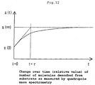
- the graph of Fig. 12 shows the change over time in the quantity n(t) (relative value) of gas molecules desorbed from the surface of the substrate being measured by the quadrupole mass spectrometer.
- the substrate temperature desirable falls with a range of 1,100-1,370°C.
- substrates suitable for use in forming silicon carbide are Si, SiC, TiC, sapphire, and diamond.
- Fig. 3 describes the case of condition 1.
- the carbon source is temporarily supplied (at pc2), the formation of the silicon layer on the substrate surface is inhibited and the silicon layer that formed on the substrate surface prior to the introduction of the carbon source simultaneously reacts with the carbon source, forming silicon carbide (Fig. 3(3)).
- the process of silicon layer epitaxial growth on the substrate surface and process of the formation of silicon carbide through the reaction of the silicon layer that has been epitaxially grown and the carbon source are completely separated in time, yielding single-crystal silicon carbide with few defects. Further, since the carbon source adsorption layer is segregated in the vicinity of the substrate surface during feeding of the carbon source in the present invention and the silicon source remains, as soon as feeding of the carbon source is stopped, the silicon layer grows epitaxially and the growth rate of the silicon carbide increases.
- the silicon source is incorporated into the substrate surface even during feeding of the carbon source, yielding silicon carbide in which there is a shift in crystal orientation with the underlayer, or microcrystals of silicon are picked up in the silicon carbide, precluding the effect of the present invention.
- the time during which the carbon source is fed per cycle is preferably not more than 30 sec. However, at less than 0.1 sec, it is difficult to supply an adequate carbon source.
- the interval of the intermittent supply of carbon source is desirably not less than 0.1 sec to desorb the carbon source that has adsorbed onto the substrate surface and to promote the growth of silicon on the substrate surface.
- the growth rate of the silicon carbide tends to be compromised.
- the silicon source gas and the carbon source gas employed in the manufacturing method of the present method are not specifically limited, at least one member from among the group consisting of SiH 4 , Si 2 H 6 , SiCl 4 , SiHCl 3 , SiH 2 Cl 2 , Si(CH 3 ) 4 , SiH 2 (CH 3 ) 2 , SiH(CH 3 ) 3 , and Si 2 (CH 3 ) 6 can be employed as the silicon source gas, for example. Further, at least one member from among the group consisting of CH 4 , C 3 H 8 , C 2 H 5 , C 2 H 6 , C 2 H 2 , C 2 H 4 , CCl 4 , CHF 3 , and CF 4 can be employed as the carbon source gas, for example.
- large-bore silicon carbide with few (or no) crystal defects can be manufactured with good ease of production.
- the substrate is something other than silicon carbide - single crystal silicon, for example - it is possible to manufacture large-bore silicon carbide with few (or no) crystal defects with good ease of production.
- the present invention covers methods of manufacturing silicon carbide characterized in that silicon carbide manufactured by the above-described manufacturing method of the present invention, particularly thin film silicon carbide, is employed as seed crystal, and silicon carbide is formed on this seed crystal by vapor phase epitaxy, sublimation recrystallization, or liquid deposition.
- Vapor phase epitaxy, sublimation recrystallization, and liquid deposition methods for forming silicon carbide are as follows.
- vapor phase epitaxy methods of forming silicon carbide at least two types of gas consisting of a carbon source and a silicon source, or at least one type of gas comprising both carbon and silicon, is thermally decomposed in a vapor phase or on the surface of the substrate and reacted, yielding silicon carbide on the substrate surface.
- an SiC substrate based on the present invention is employed as seed crystal, and while being heated under vacuum to 1,200°C, 1 sccm of silane gas and 0.5 sccm of propane gas are introduced, and I slm of a noble gas in the form of Ar is fed. While maintaining the pressure of the reaction system at 13.3 Pa (100 mTorr), SiC is grown again on the seed crystal SiC substrate.
- silicon carbide feedstock is charged to a graphite crucible, a seed crystal of the silicon carbide of the present invention is introduced opposite the feedstock, and while controlling the temperature of the feedstock to be somewhat higher than that of the seed crystal, the crucible is heated to not less than 2,000°C at one atmospheric pressure, causing the feedstock to sublimate and recrystallize on the seed crystal.
- Si is melted in a carbon crucible heated to 1,500°C, the surface of the silicon carbide (seed crystal) of the present invention is contacted with the liquid surface, and silicon carbide grows on the seed crystal from molten Si and suspended carbon in the molten Si.
- Silicon carbide blocks (for example, ingots and structural members) with bores of 4-6 inches (ranging from 100-160 mm) can be formed by the above-described manufacturing methods (vapor phase epitaxy, sublimation recrystallization, and liquid deposition).
- the term "bore" corresponds to the diameter of the substrate employed in the above-described manufacturing methods.
- the bore runs up to about three inches, but based on the manufacturing method of the present invention, silicon carbide blocks with bores of 4-6 inches (equivalent to 102-152 mm, ranging from 100-160 mm) can be obtained. Further, the blocks obtained have planar defect densities of not more than 10 3 /cm 2 .
- the present invention covers silicon carbide blocks characterized by bores of 10.16 - 15.24 cm (4-6 inches). These silicon carbide blocks also have planar defect densities of not more than 10 3 /cm 2 .
- the present invention further covers semiconductor elements employing the above-described silicon carbide blocks of the present invention as substrates.
- semiconductor elements are Schottky diodes, blue light-emitting diodes, and other power devices and light-emitting elements.
- these semiconductor elements can also be manufactured by methods of manufacturing composite materials including the formation of diamond and/or gallium nitride on seed crystals of silicon carbide manufactured by the above-described manufacturing method of the present invention, for example.
- Diamond can be formed on the seed crystal in the following manner.
- a seed crystal is placed in a vacuum chamber and heated to 500°C, after which propane gas is introduced into the vacuum chamber.
- the pressure within the chamber is then regulated to 1.33 Pa (10 mTorr) with an evacuation system.
- gallium nitride on seed crystal can be performed as follows.
- a silicon carbide (seed crystal) substrate obtained by the manufacturing method of the present invention is placed in a vacuum vessel and heated to 1040°C. Next, 10 slm of ammonia and 0.5 sccm of trimethylgallium are introduced into the reaction vessel, and while the various gases decompose on the seed crystal, a GaN forming reaction takes place at correct crystal position.
- the partial pressures of the silicon source gas and carbon source gas are proportional to the feed flow rates.
- the partial pressure ratio is equal to the flow rate ratio.
- the substrate was heated to a temperature of 1,200°C, and cubic silicon carbide was epitaxially grown on the upper layer thereof.
- the pressure was adjusted through the introduction of Ar to a pressure of 100 mTorr during growth.
- the growth of silicon carbide on the silicon substrate was conducted by feeding feedstock gases in the form of SiH 2 Cl 2 and C 2 H 2 .
- the ratio Ss/Sc of the attachment coefficients of SiH 2 Cl 2 and C 2 H 2 on the surface of the silicon carbide was 0.25.
- Silicon carbide was grown by feeding SiH 2 Cl 2 and C 2 H 2 at separate times. SiH 2 Cl 2 feeding was conducted continuously for 5 sec at a partial pressure of 10 sccm. Next, after stopping the feeding of gases other than Ar, C 2 H 2 was fed for 5 sec.
- the substrate was heated to a temperature of 1,200°C, and 3C-silicon carbide was epitaxially grown on the upper layer thereof.
- the pressure was adjusted through the introduction of Ar to a pressure of 100 mTorr during growth.
- the growth of silicon carbide on the silicon substrate was conducted by feeding feedstock gases in the form of SiH 2 Cl 2 and C 2 H 2 .
- the ratio Ss/Sc of the attachment coefficients of SiH 2 Cl 2 and C 2 H 2 on the surface of the silicon carbide was 0.25.
- a cold wall CVD device was employed in the present embodiment, a hot wall type CVD device may also be employed to achieve results identical to those of the present embodiment.
- the silicon ⁇ 001 ⁇ plane was employed as substrate, the same rapid growth and crystal properties as in the present embodiment can be achieved using the silicon ⁇ 111 ⁇ plane, cubic silicon carbide ⁇ 001 ⁇ plane, cubic silicon carbide ⁇ 111 ⁇ plane, cubic silicon carbide ⁇ -1,-1,-1 ⁇ plane, hexagonal silicon carbide ⁇ 1,1,-2,0 ⁇ plane, hexagonal silicon carbide ⁇ 0,0,0,1 ⁇ plane, hexagonal silicon carbide ⁇ 0,0,0,-1 ⁇ plane, and hexagonal silicon carbide ⁇ 1,-10,0 ⁇ plane.
- C 2 H 2 was employed as the carbon source and SiH 2 Cl 2 as the silicon source in the present embodiment, so long as the partial pressure ratio (flow rate ratio) of the carbon source to the silicon source is not less than one time and not more than ten times the attachment coefficient ratio
- at least one member selected from the group consisting of CH 4 , C 3 H 8 , C 2 H 5 , C 2 H 6 , C 2 H 4 , C 2 H 6 , CCl 4 , CHF 3 , and CF 4 can be employed as the carbon source
- at least one member selected from the group consisting of SiH 4 , Si 2 H 6 , SiCl 4 , SiHCl 3 , Si(CH 3 ) 4 , SiH 2 (CH 3 ) 2 , SiH(CH 3 ) 3 , and Si 2 (CH 3 ) 6 can be employed as the carbon source to achieve the effect of the present invention.
- the substrate was heated to a temperature of 1,200°C, and 3C-silicon carbide was epitaxially grown on the upper layer thereof.
- the pressure was adjusted through the introduction of Ar to a pressure of 13.3 Pa (100 mTorr) during growth.
- the growth of silicon carbide on the silicon substrate was conducted by feeding feedstock gases in the form of SiH 2 Cl 2 and C 2 H 2 .
- the ratio Ss/Sc of the attachment coefficients of SiH 2 Cl 2 and C 2 H 2 on the surface of the silicon carbide was 0.25.
- Table 1 shows the changes in growth rates of silicon carbide by fc2.
- fc2/fs that is, pc2/ps
- Ss/Sc 0.25
- the growth rate of silicon carbide exceeded 10 ⁇ m/hr and the effect of the present invention was apparent.
- fc2/fs that is, pc2/ps
- Ss/Sc 0.25
- fc2/fs that is, pc2/ps
- Silicon carbide grown at an fc2/fs of not less than 0.15 and not greater than 3.5 did not exhibit surface defects such as anti phase boundaries and twin crystals.
- the use of the method of manufacturing silicon carbide provided by the present invention yields a silicon carbide growth rate of 10 ⁇ m/hr or greater and improves quality.
- fc2 (sccm) fc2/fs (pc2/ps) silicon carbide growth rate ( ⁇ m/hr) 0.5 0.05 silicon precipitation 1 0.1 silicon precipitation 1.5 0.15 5 1.7 0.17 5 2 0.2 7 2.3 0.23 8 2.5 0.25 11 3 0.3 21 4 0.4 23 5 0.5 24 10 1 24 15 1.5 18 20 2 13 25 2.5 13 30 3 5 35 3.5 3 40 4 0.5 50 5 0 100 10 0 200 20 0
- the silicon ⁇ 001 ⁇ plane was employed as substrate, the same rapid growth and crystal properties as in the present embodiment can be achieved using the silicon ⁇ 111 ⁇ plane, cubic silicon carbide ⁇ 001 ⁇ plane, cubic silicon carbide ⁇ 111 ⁇ plane, cubic silicon carbide ⁇ -1,-1,-1 ⁇ plane, hexagonal silicon carbide ⁇ 1,1,-2,0 ⁇ plane, hexagonal silicon carbide ⁇ 0,0,0,1 ⁇ plane, hexagonal silicon carbide ⁇ 0,0,0,-1 ⁇ plane, and hexagonal silicon carbide ⁇ 1,-10,0 ⁇ plane.
- C 2 H 2 was employed as the carbon source and SiH 2 Cl 2 as the silicon source in the present embodiment, so long as the partial pressure ratio (flow rate ratio) of the carbon source to the silicon source is not less than one time and not more than ten times the attachment coefficient ratio
- at least one member selected from the group consisting of CH 4 , C 3 H 8 , C 2 H 5 , C 2 H 6 , C 2 H 4 , C 2 H 6 , CCl 4 , CHF 3 , and CF 4 can be employed as the carbon source
- at least one member selected from the group consisting of SiH 4 , Si 2 H 6 , SiCl 4 , SiHCl 3 , Si(CH 3 ) 4 , SiH 2 (CH 3 ) 2 , SiH(CH 3 ) 3 , and Si 2 (CH 3 ) 6 can be employed as the carbon source to achieve the effect of the present invention.
- the substrate was heated to a temperature of 1,300°C, and cubic silicon carbide was epitaxially grown on the upper layer thereof.
- the pressure was adjusted through the introduction of H 2 to a pressure of 60 mTorr during growth.
- the growth of silicon carbide on the silicon substrate was conducted by feeding feedstock gases in the form of SiCl 4 and C 2 H 5 .
- the ratio Ss/Sc of the attachment coefficients of SiCl 4 and C 2 H 5 on the surface of the silicon carbide was 0.68.
- Table 2 shows the changes in growth rates of silicon carbide by fc2.
- fc2/fs that is, pc2/ps
- Ss/Sc 0.78
- the growth rate of silicon carbide exceeded 10 ⁇ m/hr and the effect of the present invention was marked.
- fc2/fs that is, pc2/ps
- Ss/Sc 0.68
- fc2/fs that is, pc2/ps
- fc2/fs that is, pc2/ps
- fc2/fs exceeded 6.8, the level of adsorption of C 2 H 5 on the substrate surface increased. Since adsorption of SiCl 4 was blocked, the growth rate of silicon carbide dropped precipitously, precluding the effect of the present invention.
- Silicon carbide grown at an fc2/fs that is, pc2/ps
- pc2/ps that is, pc2/ps
- the use of the method of manufacturing silicon carbide provided by the present invention yields a silicon carbide growth rate of 10 ⁇ m/hr or greater and improves quality.
- fc2 (sccm) fc2/fs (pc2/ps) silicon carbide growth rate ( ⁇ m/hr) 0.5 0.025 silicon precipitation 1 0.05 silicon precipitation 1.5 0.075 silicon precipitation 1.7 0.085 silicon precipitation 2 0.1 1.2 2.3 0.115 1.5 2.5 0.125 1.5 3 0.15 1.5 4 0.2 2.1 5 0.25 3.8 10 0.5 6.7 15 0.75 22 20 1 71 25 1.25 67 30 1.5 65 35 1.75 65 40 2 61 50 2.5 61 100 5 52 200 10 0
- the silicon ⁇ 001 ⁇ plane was employed as substrate, the same rapid growth and crystal properties as in the present embodiment can be achieved using the silicon ⁇ 111 ⁇ plane, cubic silicon carbide ⁇ 001 ⁇ plane, cubic silicon carbide ⁇ 111 ⁇ plane, cubic silicon carbide ⁇ -1,-1,-1 ⁇ plane, hexagonal silicon carbide ⁇ 1,1,-2,0 ⁇ plane, hexagonal silicon carbide ⁇ 0,0,0,1 ⁇ plane, hexagonal silicon carbide ⁇ 0,0,0,4 ⁇ plane, and hexagonal silicon carbide ⁇ 1,-10,0 ⁇ plane.
- C 2 H 5 was employed as the carbon source and SiCl 4 as the silicon source in the present embodiment, so long as the partial pressure ratio (flow rate ratio) of the carbon source to the silicon source is not less than one time and not more than ten times the attachment coefficient ratio
- at least one member selected from the group consisting of CH 4 , C 3 H 8 , C 2 H 2 , C 2 H 6 , C 2 H 4 , C 2 H 6 , CCl 4 , CHF 3 , and CF 4 can be employed as the carbon source
- at least one member selected from the group consisting of SiH 4 , Si 2 H 6 , SiH 2 Cl 2 , SiHCl 3 , Si(CH 3 ) 4 , SiH 2 (CH 3 ) 2 , SiH(CH 3 ) 3 , and Si 2 (CH 3 ) 6 can be employed as the carbon source to achieve the effect of the present invention.
- the substrate was heated to a temperature of 1,200°C, and cubic silicon carbide was epitaxially grown on the upper layer thereof.
- the pressure was adjusted through the introduction of Ar to a pressure of 100 mTorr during growth.
- the growth of silicon carbide on the silicon substrate was conducted by feeding feedstock gases in the form of SiH 2 Cl 2 and C 2 H 2 .
- the ratio Ss/Sc of the attachment coefficients of SiH 2 Cl 2 and C 2 H 2 on the surface of the silicon carbide was 0.25.
- C 2 H 2 While continuously feeding SiH 2 Cl 2 , C 2 H 2 was intermittently fed to grow silicon carbide.
- C 2 H 2 was intermittently fed 1,000 times at intervals of 5 sec for 5 sec each time.
- the flow rate fs of SiH 2 Cl 2 was treated as a parameter and fs was varied from 15 sccm to 200 sccm and the change in silicon carbide growth rate was observed.
- Table 3 shows the changes in growth rates of silicon carbide by fs.
- fc2/fs that is, pc2/ps
- Ss/Sc 0.25
- the growth rate of silicon carbide exceeded 10 ⁇ m/hr and the effect of the present invention was apparent.
- fc2/fs that is, pc2/ps
- fc2/fs that is, pc2/ps
- Ss/Sc 0.25
- Silicon carbide grown at an fc2/fs that is, pc2/ps
- pc2/ps that is, pc2/ps
- the use of the method of manufacturing silicon carbide provided by the present invention yields a silicon carbide growth rate of 10 ⁇ m/hr or greater and improves quality.
- fc2 (sccm) fc2/fs (pc2/ps) silicon carbide growth rate ( ⁇ m/hr) 0.1 100 0 0.5 20 0 1 10 5 5 2 13 10 1 24 15 0.67 24 20 0.5 24 25 0.4 23 30 0.33 21 35 0.29 17 40 0.25 11 45 0.22 7 50 0.2 7 60 0.17 5 70 0.14 5 80 0.13 Silicon precipitation 90 0.11 Silicon precipitation 100 0.1 Silicon precipitation 150 0.067 Silicon precipitation 200 0.05 Silicon precipitation
- the silicon ⁇ 001 ⁇ plane was employed as substrate, the same rapid growth and crystal properties as in the present embodiment can be achieved using the silicon ⁇ 111 ⁇ plane, cubic silicon carbide ⁇ 001 ⁇ plane, cubic silicon carbide ⁇ 111 ⁇ plane, cubic silicon carbide ⁇ -1,-1,-1 ⁇ plane, hexagonal silicon carbide ⁇ 1,1,-2,0 ⁇ plane, hexagonal silicon carbide ⁇ 0,0,0,1 ⁇ plane, hexagonal silicon carbide ⁇ 0,0,0,-1 ⁇ plane, and hexagonal silicon carbide ⁇ 1,-10,0 ⁇ plane.
- C 2 H 2 was employed as the carbon source and SiH 2 Cl 2 as the silicon source in the present embodiment, so long as the partial pressure ratio (flow rate ratio) of the carbon source to the silicon source is not less than one time and not more than ten times the attachment coefficient ratio
- at least one member selected from the group consisting of CH 4 , C 3 H 8 , C 2 H 5 , C 2 H 6 , C 2 H 4 , C 2 H 6 , CCl 4 , CHF 3 , and CF 4 can be employed as the carbon source
- at least one member selected from the group consisting of SiH 4 , Si 2 H 6 , SiCl 4 , SiHCl 3 , Si(CH 3 ) 4 , SiH 2 (CH 3 ) 2 , SiH(CH 3 ) 3 , and Si 2 (CH 3 ) 6 can be employed as the carbon source to achieve the effect of the present invention.
- the substrate was heated to a temperature of 1,200°C, and cubic silicon carbide was epitaxially grown on the upper layer thereof.
- the pressure was adjusted through the introduction of Ar to a pressure of 13.3 Pa (100 mTorr) during growth.
- the growth of silicon carbide on the silicon substrate was conducted by feeding feedstock gases in the form of SiH 2 Cl 2 and C 2 H 2 .
- the ratio Ss/Sc of the attachment coefficients of SiH 2 Cl 2 and C 2 H 2 on the surface of the silicon carbide was 0.25.
- Table 4 shows the changes in growth rates of silicon carbide based on tc.
- tc was less than 0.1 sec, although the growth rate of silicon carbide exceeded 10 ⁇ m/hr, the reaction between C 2 H 2 and SiH 2 Cl 2 was promoted in the vapor phase. Since the formation of silicon carbide was impeded at semicrystal positions, single crystal silicon carbide was not obtained.
- tc exceeded 30 sec, the growth time of silicon carbide lengthened and the adsorption of C 2 H 2 on the substrate surface inhibited the adsorption of SiH 2 Cl 2 , causing the growth rate of silicon carbide to drop below 10 ⁇ m/hr. Accordingly, the effect of the present invention appears at a tc of not less than 0.1 sec and not greater than 30 sec.
- Silicon carbide grown at a tc of not less than 0.1 sec and not more than 45 sec did not exhibit surface defects such as anti phase boundaries and twin crystals.
- the use of the method of manufacturing silicon carbide provided by the present invention yields a silicon carbide growth rate of 10 ⁇ m/hr or greater and improves quality.
- tc (sec) Growth rate of silicon carbide ( ⁇ m/hr) Crystal properties 0 87 formation of silicon layer 0.05 85 polycrystal 0.1 70 single crystal 0.5 69 single crystal 1 62 single crystal 3 64 single crystal 5 61 single crystal 8 58 single crystal 10 61 single crystal 15 40 single crystal 20 35 single crystal 25 21 single crystal 30 11 single crystal 35 7 single crystal 40 7 single crystal 45 5 single crystal 50 0 60 0
- the silicon ⁇ 001 ⁇ plane was employed as substrate, the same rapid growth and crystal properties as in the present embodiment can be achieved using the silicon ⁇ 111 ⁇ plane, cubic silicon carbide ⁇ 001 ⁇ plane, cubic silicon carbide ⁇ 111 ⁇ plane, cubic silicon carbide ⁇ -1,-1,-1 ⁇ plane, hexagonal silicon carbide ⁇ 1,1,-2,0 ⁇ plane, hexagonal silicon carbide ⁇ 0,0,0,1 ⁇ plane, hexagonal silicon carbide ⁇ 0,0,0,-1 ⁇ plane, and hexagonal silicon carbide ⁇ 1,-10,0 ⁇ plane.
- C 2 H 2 was employed as the carbon source and SiH 2 Cl 2 as the silicon source in the present embodiment, so long as the partial pressure ratio (flow rate ratio) of the carbon source to the silicon source is not less than one time and not more than ten times the attachment coefficient ratio
- at least one member selected from the group consisting of CH 4 , C 3 H 8 , C 2 H 5 , C 2 H 6 , C 2 H 4 , C 2 H 6 , CCl 4 , CHF 3 , and CF 4 can be employed as the carbon source
- at least one member selected from the group consisting of SiH 4 , Si 2 H 6 , SiCl 4 , SiHCl 3 , Si(CH 3 ) 4 , SiH 2 (CH 3 ) 2 , SiH(CH 3 ) 3 , and Si 2 (CH 3 ) 6 can be employed as the carbon source to achieve the effect of the present invention.
- Seed crystals were prepared from the silicon carbides obtained in Embodiments 1-5 and silicon carbide was grown by vapor growth epitaxy on the surfaces of these seed crystals.
- the silicon carbide obtained in Embodiments 1-5 can be employed as seed crystal, upon which diamond, gallium nitride (GaN), or diamond and gallium nitride may be formed to obtain composite materials comprised of silicon carbide and diamond, composite materials comprised of silicon carbide and gallium nitride, and composite materials comprised of silicon carbide, diamond, and gallium nitride.
- GaN gallium nitride
- diamond and gallium nitride may be formed to obtain composite materials comprised of silicon carbide and diamond, composite materials comprised of silicon carbide and gallium nitride, and composite materials comprised of silicon carbide, diamond, and gallium nitride.
- a seed crystal of cubic silicon carbide grown on an Si (001) substrate and prepared based on the present invention was placed in a vacuum chamber and heated to 500°C. Propane gas was then introduced into the vacuum chamber and the gas evacuation system was adjusted to generate a pressure within the chamber of 1.33 Pa (10 mTorr). Next, a 13.56 MHz high-frequency (200 W) was applied between the seed crystal and a flat electrode facing the seed crystal to form a plasma. Carbon decomposing due to the plasma was deposited on the seed crystal and kept in the proper crystal position, forming diamond on the seed crystal. The crystal orientation of the diamond surface was the (001) plane, as was that of the seed crystal, and the planar defect density decreased to 120/cm 2 . Thus, it was possible to obtain extremely high quality diamond with a large (15.24 cm (6 inch)) bore.
- Gallium nitride was also formed on a seed crystal in the following manner.
- a substrate (seed crystal) of silicon carbide obtained by the manufacturing method of the present invention was placed in a vacuum chamber and heated to 1,040°C. Next, 10 slm of ammonia and 0.5 sccm of trimethylgallium were introduced into the reaction vessel, and while the gases decomposed over the seed crystal, GaN formed at the proper crystal position.
- the GaN that formed was, like the seed crystal, a cubic crystal the surface of which was the (001) plane.
- the planar defect density was 700/cm 2 , identical to the seed crystal. Thus, it was possible to obtain extremely high quality GaN of large 15.24 (6 inch) bore.
- gold and nickel electrodes were formed by the usual methods on a composite material consisting of diamond formed on the above-described silicon carbide to prepare Schottky barrier diodes.
- Blue light emitting diodes were obtained using a composite material consisting of gallium nitride formed on the above-described silicon carbide.
- silicon carbide and composite materials can be obtained in which crystal defects are suppressed.
Abstract

Description
- The present invention relates to methods of manufacturing silicon carbide (for example, thin films and ingots) employed as a substrate material in semiconductor devices and X-ray masks, chiefly silicon carbide employed in the components of semiconductor manufacturing devices, dummy wafers employed in semiconductor element manufacturing steps, and silicon carbide structural members (for example, heaters, anticorrosion products (screws, bearings), and the like).
- Silicon carbide is a semiconductor with a broad forbidden bandwidth of 2.2 eV or greater and is a thermally, chemically, and mechanically stable crystal. Further, due to high thermal conductivity, its application as a semiconductor material under conditions of high frequency, high power, high temperature, and the like is anticipated.
- Methods of manufacturing silicon carbide include reacting coke and silicon on a heated carbon surface and precipitating silicon carbide on a carbon surface (the Atchison method); heating and sublimating silicon carbide formed by the Atchison method and recrystallizing it (sublimation method, improved Reilly method); the liquid deposition method in which silicon is melted in a carbon crucible and the suspended carbon and silicon are reacted in the crucible while drawing the product upward; and the like.
- Methods employed to obtain high purity silicon carbide films with few planar defects include chemical vapor deposition (CVD) in which a carbon source gas and a silicon source gas are thermally reacted at ordinary pressure or under a reduced pressure atmosphere and precipitated onto a substrate surface; and atomic layer epitaxy (ALE) in which a silicon source and a carbon source are alternately adsorbed onto a substrate surface, and epitaxially growing silicon carbide while extending the crystalline properties of the substrate.
- Although the Atchison method produces inexpensive, large quantities of silicon carbide, the precipitating silicon carbide is amorphous, comprising crystalline polymorphism and large quantities of impurities. In particular, this method cannot be employed to manufacture semiconductor materials in which defects and impurities are problematic.
- The improved Reilly method reduces the problems of crystalline polymorphism, amorphism, and the like associated with the Atchison method. However, it is difficult to reduce the impurities incorporated into the crystal, and increasing the area of the crystal and decreasing the number of defects are no simple tasks.
- The method that is generally employed to reduce the crystal defects and impurities that are problematic in the improved Reilly method is to use CVD or ALE to epitaxially grow silicon carbide while reducing the defect density and impurities on a silicon carbide substrate obtained by the improved Reilly method. However, since the area of the crystals obtained by these methods is limited to the area of the silicon carbide obtained by the improved Reilly method, large-area, high-quality silicon carbide cannot be obtained.
- To increase the area of silicon carbide, the general method has been devised of using CVD or ALE to heteroepitaxially grow a silicon carbide layer on a single crystal silicon substrate employed as a semiconductor material. However, high concentrations of defects are produced at the interface of the silicon substrate and the silicon carbide. Thus, the quality of the crystal is poorer than that of epitaxially grown silicon carbide layers formed on silicon carbide substrates obtained by the improved Reilly method. When employing heteroepitaxial growth, crystal quality can be improved by increasing the thickness of the film of silicon carbide being grown. However, since the rate of silicon carbide growth by CVD or ALE is extremely low, the application of silicon carbide obtained by heteroepitaxial growth is currently impeded.
- The rate of growth of silicon carbide can be increased to some extent by increasing the partial pressure of the starting gasses using CVD. However, the faster the growth rate, the more crystal defects tend to increase in the silicon carbide. Since the ALE method requires that a certain quantity of atoms or molecules be uniformly adsorbed to the substrate surface under thermal equilibrium, increasing the growth rate of silicon carbide by increasing the amount of gas being fed as is done in CVD is undesirable.
- It is therefore the object of the present invention to provide an improved method for the production of silicon carbide and improved silicon carbide products. This object is solved by the methods of
independent claims 1, 7 and 12, the silicon carbide block of independent claim 9 and the semiconductor element according to independent claim 11. Further advantageous features, aspects and details of the invention are evident from the dependent claims, the description, the examples, embodiments, and the drawings. - According to one aspect, the present invention provides a method of manufacturing silicon carbide affording adequate ease of production by increasing the growth rate of silicon carbide in gas vapor growth without increasing crystal defects.
- According to a further aspect, the present invention provides a method of manufacturing silicon carbide of a quality suitable for use as a semiconductor element material with fewer crystal defects and affording adequate ease of production even in heteroepitaxial growth employing a substrate other than silicon carbide. A further object of the manufacturing method of the present invention is to obtain silicon carbide not just as a thin film, but also as an ingot or structural member.
- According to a still further aspect, the present invention provides silicon carbide (not just thin films, but also ingots and structural members) having heretofore unseen dimensions (bores) in the form of silicon carbide of a quality suitable for use as a semiconductor element material with reduced crystal defects.
- According to yet another aspect, the present invention provides a semiconductor element employing the above-described silicon carbide as a substrate, and to provide a method of manufacturing composite materials employing the above-described silicon carbide as seed crystal.
- The aforementioned objects can be achieved by the present invention as follows.
- In accordance with the present invention, there is provided a method of manufacturing silicon carbide by forming silicon carbide from an atmosphere containing a silicon carbide feedstock gas on a substrate surface, characterized in that:
said silicon carbide feedstock gas comprises at least a silicon source gas and a carbon source gas;
the partial pressure ps of said silicon source gas in said atmosphere is constant (with ps>0), the partial pressure of said carbon source gas in said atmosphere consists of a state pc1 and a state pc2 that are repeated in alternating fashion (referred to ascondition 1 below);
(where pc1 and pc2 denote partial pressures of said carbon source gas, pc1>pc2, and the partial pressure ratio (pc1/ps) falls within a range of 1-10 times the attachment coefficient ratio (Ss/Sc), the partial pressure ratio (pc2/ps) falls within a range of less than one time the attachment coefficient ratio (Ss/Sc)
(where Ss denotes the attachment coefficient of silicon source gas to the silicon carbide substrate at the substrate temperature during formation of said silicon carbide, and Sc denotes the attachment coefficient of carbon source gas to the silicon carbide substrate at the substrate temperature during the forming of said silicon carbide))
or
the partial pressure pc of said carbon source gas in said atmosphere is constant (with pc>0), the partial pressure of said silicon source gas in said atmosphere consists of a state ps1 and a state ps2 that are repeated in alternating fashion (referred to ascondition 2 below);
(where ps and ps2 denote partial pressures of said silicon source gas, ps1<ps2, and the partial pressure ratio (pc/ps1) falls within a range of 1-10 times the attachment coefficient ratio (Ss/Sc), the partial pressure ratio (pc/ps2) falls within a range of less than one time the attachment coefficient ratio (Ss/Sc)
(where Ss denotes the attachment coefficient of silicon source gas to the silicon carbide substrate at the substrate temperature during formation of said silicon carbide, and Sc denotes the attachment coefficient of carbon source gas to the silicon carbide substrate at the substrate temperature during the forming of said silicon carbide)). - In the above manufacturing method of silicon carbide, the following conditions are preferred.
- In
condition 1, pc1 and pc2 each continue for a prescribed period, and incondition 2, ps1 and ps2 each continue for a prescribed period. - Silicon carbide is formed on a substrate the temperature of which is not less than 900°C.
- The above silicon source gas is at least one member selected from the group consisting of SiH4, Si2H6, SiCl4, SiHCl3, SiH2Cl2, Si(CH3)4, SiH2(CH3)2, SiH(CH3)3, and Si2(CH3)6, and/or said carbon source gas is at least one member selected from the group consisting of CH4, C3H8, C2H5, C2H6, C2H2, C2H4, CCl4, CHF3, and CF4.
- Pc2 or ps1 is essentially 0.
- Pc2 is essentially 0, the time during which the partial pressure of the carbon source gas is set to pc1 is 0.1-30 seconds, and the time during which the partial pressure of the carbon source gas is set to pc2 is 0.1-30 seconds.
- The present invention further relates to a method of manufacturing silicon carbide characterized in that the silicon carbide manufactured in any of claims 1-6 is employed as seed crystal and in that silicon carbide is formed on said seed crystal by vapor phase epitaxy, sublimation recrystallization, or liquid deposition.
- In the above manufacturing method of silicon carbide, the preferred is that silicon carbide blocks 10.16 - 15.24 cm (4-6 inches) in bore are formed by vapor phase epitaxy, sublimation recrystallization, or liquid deposition.
- The present invention further relates to a silicon carbide block characterized by having a bore of 10.16 - 15.24 cm (4-6 inches).
- In the above silicon carbide block, the preferred is that the planar defect density is not more than 103/cm2.
- The present invention further relates to a semiconductor element employing as substrate the silicon carbide block described above.
- The present invention further relates to a method of manufacturing composite materials characterized in that silicon carbide manufactured by the above-mentioned method is employed as seed crystal and diamond and/or gallium nitride is formed on said seed crystal.
-
- Fig. 1 is an example of the cycle of
condition 1 of the present invention. - Fig. 2 is an example of the cycle of
condition 2 of the present invention. - Fig. 3 is a type drawing descriptive of the operation of the present invention: (1) shows how the silicon source is fed onto the substrate, (2) shows how the silicon source fed onto the substrate forms an epitaxial growth layer of silicon, (3) shows how the epitaxial growth layer of silicon formed on the substrate reacts with the carbon source to form silicon carbide, and (4) shows how the carbon source forms an adsorption layer on the silicon carbide layer, impeding adsorption of the silicon source.
- Fig. 4 is the method of supplying feedstock gas in Comparative Example 1.
- Fig. 5 is the method of supplying feedstock gas in
Embodiment 1. - Fig. 6 is the method of supplying feedstock gas in
Embodiment 2. - Fig. 7 is the method of supplying feedstock gas in
Embodiment 3. - Fig. 8 is the method of supplying feedstock gas in Embodiment 4.
- Fig. 9 is the method of supplying feedstock gas in Embodiment 5.
- Fig. 10 is a schematic drawing of the method used to measure the attachment coefficient ratio.
- Fig. 11 is a graph showing the change over time of the quantity of gas that is fed.
- Fig. 12 is a graph showing the change over time of the number n(t) (relative value) of gas molecules desorbing from the substrate surface as measured by quadrupole mass spectrometry.
-
- The method of manufacturing silicon carbide of the present invention is chiefly a method of manufacturing thin films of silicon carbide on a substrate surface from an atmosphere containing silicon carbide feedstock gases. However, it is not limited to thin films of silicon carbide, and can be used to manufacture silicon carbide ingots and structural members of silicon carbide.
- The method of manufacturing silicon carbide of the present invention is characterized by
conditions - Condition 1: The silicon carbide feedstock gas comprises at least a silicon source gas and a carbon source gas. The partial pressure ps of the silicon source gas in the atmosphere is constant (with ps>0), and the partial pressure of the carbon source gas repeatedly alternates between a state pc1 and a state pc2.
- Condition 2: The silicon carbide feedstock gas comprises at least a silicon source gas and a carbon source gas. The partial pressure pc of the carbon source gas is constant (with pc>0), and the partial pressure of the silicon source gas repeatedly alternates between a state ps and a state ps2.
- Fig. 1 shows an example of the cycle of
condition 1. - In
condition 1, the partial pressure ps of the silicon source gas is constant in the atmosphere. However, ps>0. The partial pressure of the carbon source gas in the atmosphere repeatedly alternates between a state pc1 and a state pc2. That is, since pc1>pc2, the partial pressure of the carbon source gas is increased. Although pc1>pc2, pc2 can essentially be 0. What is meant in the present Specification by the partial pressure being essentially 0 is not greater than 10-5 Torr. The time (tc1) during which the pressure of the carbon source gas is made pc1 and the time (tc2) during which the partial pressure of the carbon source gas is made pc2 are repeatedly alternated. - In
condition 1, during time tc2 when the partial pressure of the carbon source gas is made pc2, the partial pressure of the carbon source gas is lower than the silicon source gas, and so long as pc2 is not zero, silicon carbide precipitates. However, Si also precipitates in this state. Subsequently, during time tc1 when the partial pressure of the carbon source gas is pc1, the partial pressure of the carbon source gas becomes relatively high, and simultaneously with the precipitation of silicon carbide, Si reacts with C supplied by the silicon source gas, creating silicon carbide. To permit the creation of such states, tc1 and tc2, ps, pc1 and pc2, the type of silicon source gas and carbon source gas, the substrate temperature, the capacity of the reaction vessel, and the like are considered and suitably determined. For example, tc1 can be set to within a range of 0.1-60 sec and tc2 to within a range of 0.1-90 sec. Setting pc2 to 0; setting time tc1, when the partial pressure of the carbon gas is set to pc1, to 0.1-30 sec; and setting time tc2, when the partial pressure of the carbon source gas is set to pc2, to 0.1-30 sec is particularly desirable from the viewpoint of decreasing crystal defects in the silicon carbide and increasing the growth rate. - Further, in
condition 1, the partial pressure ratio (pc1/ps) is set to within a range of 1-10 times the attachment coefficient ratio (Ss/Sc) and the partial gas ratio (pc2/ps) is set to within a range of less than one time the attachment coefficient ratio (Ss/Sc). Thus, during time tc2 when the partial pressure of the carbon source gas is pc2, silicon carbide and Si precipitate simultaneously, and subsequently, during time tc1 when the partial pressure of the carbon source gas is pc1, the precipitation of silicon carbide and the formation of silicon carbide through the reaction of precipitated Si and C occur simultaneously. The attachment coefficient ratio (Ss/Sc) can be calculated by a method described further below. - An example of the cycle of
condition 2 is shown in Fig. 2. - In
condition 2, the partial pressure pc of the carbon source gas in the atmosphere is held constant. However, pc>0. The state where the partial pressure of the silicon source gas in the atmosphere isps 1 and the state in which it is ps2 are repeatedly alternated. That is, since ps1<ps2, the partial pressure of the silicon source gas is increased. Although ps1<ps2, ps1 can be essentially 0. The time (ts1) during which the partial pressure of the silicon source gas is made ps1 and the time (ts2) during which the partial pressure of the silicon gas source is made ps2 are repeatedly alternated. - In
condition 2, during time ts2 when the partial pressure of the silicon source gas is made ps2, the partial pressure of the carbon source gas is lower than that of the silicon source gas and silicon carbide precipitates, but Si also precipitates during that state. Subsequently, during time ts1 when the partial pressure of the silicon source gas is made ps1, the partial pressure of the silicon source gas becomes relatively low, and Si reacts with C supplied by the carbon source gas to form silicon carbide simultaneously with the precipitation of silicon carbide. To permit the creation of such states, ts1 and ts2, pc, ps1 and ps2, the type of silicon source gas and carbon source gas, the substrate temperature, the capacity of the reaction vessel, and the like are considered and suitably determined. For example, ts1 can be set to within a range of 0.1-60 sec and ts2 to within a range of 0.1-60 sec. - Further, in
condition 2, partial pressure ratio (pc/ps1) is set to within a range of 1-10 times the attachment coefficient ratio (Ss/Sc), and partial pressure ratio (pc/ps2) is set to within a range of less than one time attachment coefficient ratio (Ss/Sc). Thus, during time ts2 when the partial pressure of the silicon source gas is ps2, precipitation of silicon carbide and Si occurs simultaneously, and subsequently, duringtime ts 1 when the partial pressure of the silicon source gas is ps1, precipitation of silicon carbide and the formation of silicon carbide through the reaction of precipitated Si and C occur simultaneously. - Attachment coefficient ratio (Ss/Sc) can be determined in the following manner.
- A valve is used to blow a pulse of either the carbon source gas or the silicon source gas onto the surface of the silicon carbide substrate. The temperature of the silicon carbide substrate is preset to the substrate temperature for forming silicon carbide.
- The partial pressure at T=0 is instantaneously raised to a fixed level.
- Gas molecules temporarily attached to the surface of the substrate are desorbed, but the quantity (a relative value) of the gas molecules that are desorbed is monitored with a quadrupole mass spectrometer. A collimator is positioned between the substrate and the quadrupole mass spectrometer so that in this process, just the gas molecules that are desorbed from the substrate enter the mass spectrometer. (Fig. 10 is a schematic of the measurement system.)
- The graph of Fig. 11 shows the change over time of the level of gas supply. The graph of Fig. 12 shows the change over time in the quantity n(t) (relative value) of gas molecules desorbed from the surface of the substrate being measured by the quadrupole mass spectrometer.
- Let τdenote the time coordinates of the point of intersection of the tangent of n(t) when t=0 and the asymptotic line when τ→ ∞. Let τc (the average residence time of the carbon source gas on the surface of the substrate) denote τwhen the gas employed is the carbon source gas. Let τs (the average residence time of the silicon source gas on the surface of the substrate) denote τwhen the gas employed is the silicon source gas. The attachment coefficient ratio can then be calculated from the relation Sc/Ss= τc/τs.
- During the formation of silicon carbide by the manufacturing method of the present invention, setting the substrate temperature to not less than 900°C promotes the decomposition of molecules adhering to the substrate surface and promotes the reaction, and is suitable from the viewpoint of making it possible to establish a prescribed relation (the relation specified by
condition 1 and condition 2) between the partial pressure ratio and the attachment coefficient ratio that is independent of the types of gas. The substrate temperature desirable falls with a range of 1,100-1,370°C. - Examples of substrates suitable for use in forming silicon carbide are Si, SiC, TiC, sapphire, and diamond.
- The operation of the manufacturing method of the present invention will be described based on Fig. 3. Fig. 3 describes the case of
condition 1. - As shown by Fig. 3 (1), when a silicon source is continuously fed to the substrate surface (ps=constant, pc2=0), the silicon source thermally decomposes, for example, on the surface of the substrate that has been heated to not less than 900°C and a single crystal of silicon forms on the substrate surface (Fig. 3(2)). Here, when the carbon source is temporarily supplied (at pc2), the formation of the silicon layer on the substrate surface is inhibited and the silicon layer that formed on the substrate surface prior to the introduction of the carbon source simultaneously reacts with the carbon source, forming silicon carbide (Fig. 3(3)). In this process, when the partial pressure of the carbon source has been set to pc2, the attachment coefficient of the carbon source to Sc, the partial pressure of the silicon source to ps, and the attachment coefficient of the silicon source to Ss, and when pc2 or ps is controlled to maintain a relation where pc2/ps during the carbon source supply is not less than one time and not more than ten times Ss/Sc, the incorporation of the silicon source onto the substrate surface is inhibited during feeding of the carbon source (Fig. 3(4)).
- When the carbon source is fed intermittently as set forth above, the process of silicon layer epitaxial growth on the substrate surface and process of the formation of silicon carbide through the reaction of the silicon layer that has been epitaxially grown and the carbon source are completely separated in time, yielding single-crystal silicon carbide with few defects. Further, since the carbon source adsorption layer is segregated in the vicinity of the substrate surface during feeding of the carbon source in the present invention and the silicon source remains, as soon as feeding of the carbon source is stopped, the silicon layer grows epitaxially and the growth rate of the silicon carbide increases. However, when pc2/ps falls below Ss/Sc, the silicon source is incorporated into the substrate surface even during feeding of the carbon source, yielding silicon carbide in which there is a shift in crystal orientation with the underlayer, or microcrystals of silicon are picked up in the silicon carbide, precluding the effect of the present invention. To achieve adequate mass production (growth rate of silicon carbide) based on the present invention, the time during which the carbon source is fed per cycle is preferably not more than 30 sec. However, at less than 0.1 sec, it is difficult to supply an adequate carbon source. The interval of the intermittent supply of carbon source is desirably not less than 0.1 sec to desorb the carbon source that has adsorbed onto the substrate surface and to promote the growth of silicon on the substrate surface. However, at greater than 30 sec, the growth rate of the silicon carbide tends to be compromised.
- Mechanism of deposition of silicon carbide and the like in
condition 1 has been described above; that ofcondition 2 is substantially identical therewith. - Although the silicon source gas and the carbon source gas employed in the manufacturing method of the present method are not specifically limited, at least one member from among the group consisting of SiH4, Si2H6, SiCl4, SiHCl3, SiH2Cl2, Si(CH3)4, SiH2(CH3)2, SiH(CH3)3, and Si2(CH3)6 can be employed as the silicon source gas, for example. Further, at least one member from among the group consisting of CH4, C3H8, C2H5, C2H6, C2H2, C2H4, CCl4, CHF3, and CF4 can be employed as the carbon source gas, for example.
- Based on the method of manufacturing silicon carbide of the present invention as set forth above, large-bore silicon carbide with few (or no) crystal defects can be manufactured with good ease of production. In particular, even when the substrate is something other than silicon carbide - single crystal silicon, for example - it is possible to manufacture large-bore silicon carbide with few (or no) crystal defects with good ease of production.
- The present invention covers methods of manufacturing silicon carbide characterized in that silicon carbide manufactured by the above-described manufacturing method of the present invention, particularly thin film silicon carbide, is employed as seed crystal, and silicon carbide is formed on this seed crystal by vapor phase epitaxy, sublimation recrystallization, or liquid deposition.
- Vapor phase epitaxy, sublimation recrystallization, and liquid deposition methods for forming silicon carbide are as follows.
- In vapor phase epitaxy methods of forming silicon carbide, at least two types of gas consisting of a carbon source and a silicon source, or at least one type of gas comprising both carbon and silicon, is thermally decomposed in a vapor phase or on the surface of the substrate and reacted, yielding silicon carbide on the substrate surface. For example, an SiC substrate based on the present invention is employed as seed crystal, and while being heated under vacuum to 1,200°C, 1 sccm of silane gas and 0.5 sccm of propane gas are introduced, and I slm of a noble gas in the form of Ar is fed. While maintaining the pressure of the reaction system at 13.3 Pa (100 mTorr), SiC is grown again on the seed crystal SiC substrate.
- In sublimation recrystallization methods of forming silicon carbide, silicon carbide feedstock is charged to a graphite crucible, a seed crystal of the silicon carbide of the present invention is introduced opposite the feedstock, and while controlling the temperature of the feedstock to be somewhat higher than that of the seed crystal, the crucible is heated to not less than 2,000°C at one atmospheric pressure, causing the feedstock to sublimate and recrystallize on the seed crystal.
- In liquid deposition methods of forming silicon carbide, Si is melted in a carbon crucible heated to 1,500°C, the surface of the silicon carbide (seed crystal) of the present invention is contacted with the liquid surface, and silicon carbide grows on the seed crystal from molten Si and suspended carbon in the molten Si.
- Silicon carbide blocks (for example, ingots and structural members) with bores of 4-6 inches (ranging from 100-160 mm) can be formed by the above-described manufacturing methods (vapor phase epitaxy, sublimation recrystallization, and liquid deposition). Here, the term "bore" corresponds to the diameter of the substrate employed in the above-described manufacturing methods. In conventional silicon carbide blocks, the bore runs up to about three inches, but based on the manufacturing method of the present invention, silicon carbide blocks with bores of 4-6 inches (equivalent to 102-152 mm, ranging from 100-160 mm) can be obtained. Further, the blocks obtained have planar defect densities of not more than 103/cm2.
- Accordingly, the present invention covers silicon carbide blocks characterized by bores of 10.16 - 15.24 cm (4-6 inches). These silicon carbide blocks also have planar defect densities of not more than 103/cm2.
- The present invention further covers semiconductor elements employing the above-described silicon carbide blocks of the present invention as substrates. Examples of such semiconductor elements are Schottky diodes, blue light-emitting diodes, and other power devices and light-emitting elements.
- Further, these semiconductor elements can also be manufactured by methods of manufacturing composite materials including the formation of diamond and/or gallium nitride on seed crystals of silicon carbide manufactured by the above-described manufacturing method of the present invention, for example.
- Diamond can be formed on the seed crystal in the following manner.
- A seed crystal is placed in a vacuum chamber and heated to 500°C, after which propane gas is introduced into the vacuum chamber. The pressure within the chamber is then regulated to 1.33 Pa (10 mTorr) with an evacuation system. Next, a high frequency
- of 13.56 MHz (200 W) is applied between the seed crystal and a flat electrode facing the seed crystal and a plasma is formed. The carbon decomposed by the plasma is deposited on the seed crystal and remains at the correct crystal position to form diamond on the seed crystal.
- Further, the formation of gallium nitride on seed crystal can be performed as follows.
- A silicon carbide (seed crystal) substrate obtained by the manufacturing method of the present invention is placed in a vacuum vessel and heated to 1040°C. Next, 10 slm of ammonia and 0.5 sccm of trimethylgallium are introduced into the reaction vessel, and while the various gases decompose on the seed crystal, a GaN forming reaction takes place at correct crystal position.
- The present disclosure relates to the subject matter contained in Japanese Patent Application No. 2000-162048 filed on May 31, 2000, which is expressly incorporated herein by reference in its entirety.
- Embodiments of the present invention are described below.
- In the embodiments and comparative examples, the partial pressures of the silicon source gas and carbon source gas are proportional to the feed flow rates. Thus, the partial pressure ratio is equal to the flow rate ratio.
- Employing the {001} plane of a single-crystal silicon substrate as the single-crystal growth substrate, the substrate was heated to a temperature of 1,200°C, and cubic silicon carbide was epitaxially grown on the upper layer thereof. Using a cold wall type CVD device, the pressure was adjusted through the introduction of Ar to a pressure of 100 mTorr during growth. The growth of silicon carbide on the silicon substrate was conducted by feeding feedstock gases in the form of SiH2Cl2 and C2H2. The ratio Ss/Sc of the attachment coefficients of SiH2Cl2 and C2H2 on the surface of the silicon carbide was 0.25.
- A comparative example will be given next based on Fig. 4. Silicon carbide was grown by feeding SiH2Cl2 and C2H2 at separate times. SiH2Cl2 feeding was conducted continuously for 5 sec at a partial pressure of 10 sccm. Next, after stopping the feeding of gases other than Ar, C2H2 was fed for 5 sec.
- After feeding C2H2 for 5 sec, the feeding of gases other than Ar was stopped, and SiH2Cl2 feeding was begun. This alternating feeding of gases was repeated 1,000 times. yielding a cubic silicon carbide film on the silicon substrate. Growing the silicon carbide took 5.56 hr. As a result of the growth, a 0.8 µm single crystal of silicon carbide was obtained on the silicon substrate. As a result, the growth rate of the silicon carbide was 0.144 µm/hr. However, surface defects such as anti phase boundaries and twin crystal bands were present on the surface of the silicon carbide at a density of 103/cm2.
- Employing the {001} plane of a single-crystal silicon substrate as the single-crystal growth substrate, the substrate was heated to a temperature of 1,200°C, and 3C-silicon carbide was epitaxially grown on the upper layer thereof. Using a cold wall type CVD device, the pressure was adjusted through the introduction of Ar to a pressure of 100 mTorr during growth. The growth of silicon carbide on the silicon substrate was conducted by feeding feedstock gases in the form of SiH2Cl2 and C2H2. The ratio Ss/Sc of the attachment coefficients of SiH2Cl2 and C2H2 on the surface of the silicon carbide was 0.25.
- The embodiment of the present invention will be described based on Fig. 5.
While continuously feeding SiH2Cl2 at a partial pressure of 10 sccm, C2H2 was intermittently fed to grow silicon carbide. The partial pressure of the SiH2Cl2 was 10 sccm. C2H2 was intermittently fed 1,000 times at intervals of 5 sec at a partial pressure of 10 sccm. Each time, the C2H2 was fed for 5 sec. Growth of silicon carbide required 2.8 hr. As a result of the growth, 67 µm of single crystal silicon carbide was obtained on the silicon substrate. The effective growth rate of silicon carbide was 24 µm/hr. Further, surface defects such as anti phase boundaries and twin crystal bands had been eliminated from the surface of the crystal obtained. In this manner, the use of the present invention permitted an accelerated rate of silicon carbide growth exceeding 10 µm/hr and permitted a substantial decrease in crystal defects. (fc2/fs=4xSs/Sc, fc1=0, that is pc2/ps=4xSs/Sc, pc1=0). - Although a cold wall CVD device was employed in the present embodiment, a hot wall type CVD device may also be employed to achieve results identical to those of the present embodiment.
- Further, although the silicon {001} plane was employed as substrate, the same rapid growth and crystal properties as in the present embodiment can be achieved using the silicon {111} plane, cubic silicon carbide {001} plane, cubic silicon carbide {111} plane, cubic silicon carbide {-1,-1,-1} plane, hexagonal silicon carbide {1,1,-2,0} plane, hexagonal silicon carbide {0,0,0,1} plane, hexagonal silicon carbide {0,0,0,-1} plane, and hexagonal silicon carbide {1,-10,0} plane.
- Although C2H2 was employed as the carbon source and SiH2Cl2 as the silicon source in the present embodiment, so long as the partial pressure ratio (flow rate ratio) of the carbon source to the silicon source is not less than one time and not more than ten times the attachment coefficient ratio, at least one member selected from the group consisting of CH4, C3H8, C2H5, C2H6, C2H4, C2H6, CCl4, CHF3, and CF4 can be employed as the carbon source, and at least one member selected from the group consisting of SiH4, Si2H6, SiCl4, SiHCl3, Si(CH3)4, SiH2(CH3)2, SiH(CH3)3, and Si2(CH3)6 can be employed as the carbon source to achieve the effect of the present invention.
- Employing the {001} plane of a single-crystal silicon substrate as the single-crystal growth substrate, the substrate was heated to a temperature of 1,200°C, and 3C-silicon carbide was epitaxially grown on the upper layer thereof. Using a cold wall type CVD device, the pressure was adjusted through the introduction of Ar to a pressure of 13.3 Pa (100 mTorr) during growth. The growth of silicon carbide on the silicon substrate was conducted by feeding feedstock gases in the form of SiH2Cl2 and C2H2. The ratio Ss/Sc of the attachment coefficients of SiH2Cl2 and C2H2 on the surface of the silicon carbide was 0.25.
- The embodiment of the present invention will be described based on Fig. 6 below.
While continuously feeding SiH2Cl2 at a flow rate of 10 sccm, C2H2 was intermittently fed to grow silicon carbide. The SiH2Cl2 flow rate was a constant 10 sccm. C2H2 was intermittently fed 1,000 times at intervals of 5 sec. Each time, C2H2 was fed for 5 sec. However, the flow rate fc of C2H2 was treated as a parameter and fc2 was varied from 0.5-200 sccm and the change in silicon carbide growth rate was observed. (fc2/fs=4xSs/Sc, fc1=0, that is pc2/ps=4xSs/Sc, pc1=0). - Table 1 shows the changes in growth rates of silicon carbide by fc2. When fc2/fs (that is, pc2/ps) was Ss/Sc (0.25) or greater, the growth rate of silicon carbide exceeded 10 µm/hr and the effect of the present invention was apparent. However, when fc2/fs (that is, pc2/ps) was less than Ss/Sc (0.25), not only did the growth rate of silicon carbide decrease, but silicon precipitated in the silicon carbide, precluding the effect of the present invention. Further, when fc2/fs (that is, pc2/ps) exceeded 2.5, the level of adsorption of C2H2 on the substrate surface increased. Since adsorption of SiH2Cl2 was blocked, the growth rate of silicon carbide dropped precipitously, precluding the effect of the present invention. Silicon carbide grown at an fc2/fs of not less than 0.15 and not greater than 3.5 did not exhibit surface defects such as anti phase boundaries and twin crystals.
- As set forth above, the use of the method of manufacturing silicon carbide provided by the present invention yields a silicon carbide growth rate of 10 µm/hr or greater and improves quality.
fc2 (sccm) fc2/fs (pc2/ps) silicon carbide growth rate (µm/hr) 0.5 0.05 silicon precipitation 1 0.1 silicon precipitation 1.5 0.15 5 1.7 0.17 5 2 0.2 7 2.3 0.23 8 2.5 0.25 11 3 0.3 21 4 0.4 23 5 0.5 24 10 1 24 15 1.5 18 20 2 13 25 2.5 13 30 3 5 35 3.5 3 40 4 0.5 50 5 0 100 10 0 200 20 0 - Although a cold wall type CVD device was employed in the present embodiment, the same effects can be achieved in the present embodiment using a hot wall type CVD device.
- Further, although the silicon {001} plane was employed as substrate, the same rapid growth and crystal properties as in the present embodiment can be achieved using the silicon {111} plane, cubic silicon carbide {001} plane, cubic silicon carbide {111} plane, cubic silicon carbide {-1,-1,-1} plane, hexagonal silicon carbide {1,1,-2,0} plane, hexagonal silicon carbide {0,0,0,1} plane, hexagonal silicon carbide {0,0,0,-1} plane, and hexagonal silicon carbide {1,-10,0} plane.
- Although C2H2 was employed as the carbon source and SiH2Cl2 as the silicon source in the present embodiment, so long as the partial pressure ratio (flow rate ratio) of the carbon source to the silicon source is not less than one time and not more than ten times the attachment coefficient ratio, at least one member selected from the group consisting of CH4, C3H8, C2H5, C2H6, C2H4, C2H6, CCl4, CHF3, and CF4 can be employed as the carbon source, and at least one member selected from the group consisting of SiH4, Si2H6, SiCl4, SiHCl3, Si(CH3)4, SiH2(CH3)2, SiH(CH3)3, and Si2(CH3)6 can be employed as the carbon source to achieve the effect of the present invention.
- Employing the {001} plane of a single-crystal silicon substrate as the single-crystal growth substrate, the substrate was heated to a temperature of 1,300°C, and cubic silicon carbide was epitaxially grown on the upper layer thereof. Using a cold wall type CVD device, the pressure was adjusted through the introduction of H2 to a pressure of 60 mTorr during growth. The growth of silicon carbide on the silicon substrate was conducted by feeding feedstock gases in the form of SiCl4 and C2H5. The ratio Ss/Sc of the attachment coefficients of SiCl4 and C2H5 on the surface of the silicon carbide was 0.68.
- The embodiment of the present invention will be described based on Fig. 7 below.
While continuously feeding SiCl4 at a flow rate of 20 sccm, C2H5 was intermittently fed to grow silicon carbide. C2H5 was fed 1,000 times at intervals of 5 sec, each time lasting 5 sec. However, the flow rate fc of C2H5 was treated as a parameter and fc2 was varied from 0.5-200 sccm and the change in silicon carbide growth rate was observed (fc1=0, that is,pc 1=0). - Table 2 shows the changes in growth rates of silicon carbide by fc2. When fc2/fs (that is, pc2/ps) was Ss/Sc (0.68) or greater, the growth rate of silicon carbide exceeded 10 µm/hr and the effect of the present invention was marked. However, when fc2/fs (that is, pc2/ps) was less than Ss/Sc (0.68), not only did the growth rate of silicon carbide decrease, but silicon precipitated in the silicon carbide, precluding the effect of the present invention. Further, when fc2/fs (that is, pc2/ps) exceeded 6.8, the level of adsorption of C2H5 on the substrate surface increased. Since adsorption of SiCl4 was blocked, the growth rate of silicon carbide dropped precipitously, precluding the effect of the present invention.
- Silicon carbide grown at an fc2/fs (that is, pc2/ps) of not less than 0.2 and not greater than 5 did not exhibit surface defects such as anti phase boundaries and twin crystals.
- As set forth above, the use of the method of manufacturing silicon carbide provided by the present invention yields a silicon carbide growth rate of 10 µm/hr or greater and improves quality.
fc2 (sccm) fc2/fs (pc2/ps) silicon carbide growth rate (µm/hr) 0.5 0.025 silicon precipitation 1 0.05 silicon precipitation 1.5 0.075 silicon precipitation 1.7 0.085 silicon precipitation 2 0.1 1.2 2.3 0.115 1.5 2.5 0.125 1.5 3 0.15 1.5 4 0.2 2.1 5 0.25 3.8 10 0.5 6.7 15 0.75 22 20 1 71 25 1.25 67 30 1.5 65 35 1.75 65 40 2 61 50 2.5 61 100 5 52 200 10 0 - Although a cold wall type CVD device was employed in the present embodiment, the same effects can be achieved in the present embodiment using a hot wall type CVD device.
- Further, although the silicon {001} plane was employed as substrate, the same rapid growth and crystal properties as in the present embodiment can be achieved using the silicon {111} plane, cubic silicon carbide {001} plane, cubic silicon carbide {111} plane, cubic silicon carbide {-1,-1,-1} plane, hexagonal silicon carbide {1,1,-2,0} plane, hexagonal silicon carbide {0,0,0,1} plane, hexagonal silicon carbide {0,0,0,4} plane, and hexagonal silicon carbide {1,-10,0} plane.
- Although C2H5 was employed as the carbon source and SiCl4 as the silicon source in the present embodiment, so long as the partial pressure ratio (flow rate ratio) of the carbon source to the silicon source is not less than one time and not more than ten times the attachment coefficient ratio, at least one member selected from the group consisting of CH4, C3H8, C2H2, C2H6, C2H4, C2H6, CCl4, CHF3, and CF4 can be employed as the carbon source, and at least one member selected from the group consisting of SiH4, Si2H6, SiH2Cl2, SiHCl3, Si(CH3)4, SiH2(CH3)2, SiH(CH3)3, and Si2(CH3)6 can be employed as the carbon source to achieve the effect of the present invention.
- Employing the {001} plane of a single-crystal silicon substrate as the single-crystal growth substrate, the substrate was heated to a temperature of 1,200°C, and cubic silicon carbide was epitaxially grown on the upper layer thereof. Using a cold wall type CVD device, the pressure was adjusted through the introduction of Ar to a pressure of 100 mTorr during growth. The growth of silicon carbide on the silicon substrate was conducted by feeding feedstock gases in the form of SiH2Cl2 and C2H2. The ratio Ss/Sc of the attachment coefficients of SiH2Cl2 and C2H2 on the surface of the silicon carbide was 0.25.
- The embodiment of the present invention will be described based on Fig. 8 below.
While continuously feeding SiH2Cl2, C2H2 was intermittently fed to grow silicon carbide. The C2H2 flow rate (fc2) was a constant 10 sccm (fc1=0, that is, pc1=0). C2H2 was intermittently fed 1,000 times at intervals of 5 sec for 5 sec each time. However, the flow rate fs of SiH2Cl2 was treated as a parameter and fs was varied from 15 sccm to 200 sccm and the change in silicon carbide growth rate was observed. - Table 3 shows the changes in growth rates of silicon carbide by fs. When fc2/fs (that is, pc2/ps) was Ss/Sc (0.25) or greater, the growth rate of silicon carbide exceeded 10 µm/hr and the effect of the present invention was apparent. However, when fc2/fs (that is, pc2/ps) was less than Ss/Sc (0.25), not only did the growth rate of silicon carbide decrease, but silicon precipitated in the silicon carbide, precluding the effect of the present invention. Further, when fc2/fs (that is, pc2/ps) exceeded 2.5, the level of adsorption of C2H2 on the substrate surface increased. Since adsorption of SiH2Cl2 was blocked, the growth rate of silicon carbide dropped precipitously, precluding the effect of the present invention.
- Silicon carbide grown at an fc2/fs (that is, pc2/ps) of not less than 0.2 and not greater than 10 did not exhibit surface defects such as anti phase boundaries and twin crystals.
- As set forth above, the use of the method of manufacturing silicon carbide provided by the present invention yields a silicon carbide growth rate of 10 µm/hr or greater and improves quality.
fc2 (sccm) fc2/fs (pc2/ps) silicon carbide growth rate (µm/hr) 0.1 100 0 0.5 20 0 1 10 5 5 2 13 10 1 24 15 0.67 24 20 0.5 24 25 0.4 23 30 0.33 21 35 0.29 17 40 0.25 11 45 0.22 7 50 0.2 7 60 0.17 5 70 0.14 5 80 0.13 Silicon precipitation 90 0.11 Silicon precipitation 100 0.1 Silicon precipitation 150 0.067 Silicon precipitation 200 0.05 Silicon precipitation - Although a cold wall type CVD device was employed in the present embodiment, the same effects can be achieved in the present embodiment using a hot wall type CVD device.
- Further, although the silicon {001} plane was employed as substrate, the same rapid growth and crystal properties as in the present embodiment can be achieved using the silicon {111} plane, cubic silicon carbide {001} plane, cubic silicon carbide {111} plane, cubic silicon carbide {-1,-1,-1} plane, hexagonal silicon carbide {1,1,-2,0} plane, hexagonal silicon carbide {0,0,0,1} plane, hexagonal silicon carbide {0,0,0,-1} plane, and hexagonal silicon carbide {1,-10,0} plane.
- Although C2H2 was employed as the carbon source and SiH2Cl2 as the silicon source in the present embodiment, so long as the partial pressure ratio (flow rate ratio) of the carbon source to the silicon source is not less than one time and not more than ten times the attachment coefficient ratio, at least one member selected from the group consisting of CH4, C3H8, C2H5, C2H6, C2H4, C2H6, CCl4, CHF3, and CF4 can be employed as the carbon source, and at least one member selected from the group consisting of SiH4, Si2H6, SiCl4, SiHCl3, Si(CH3)4, SiH2(CH3)2, SiH(CH3)3, and Si2(CH3)6 can be employed as the carbon source to achieve the effect of the present invention.
- Employing the {001} plane of a single-crystal silicon substrate as the single-crystal growth substrate, the substrate was heated to a temperature of 1,200°C, and cubic silicon carbide was epitaxially grown on the upper layer thereof. Using a cold wall type CVD device, the pressure was adjusted through the introduction of Ar to a pressure of 13.3 Pa (100 mTorr) during growth. The growth of silicon carbide on the silicon substrate was conducted by feeding feedstock gases in the form of SiH2Cl2 and C2H2. The ratio Ss/Sc of the attachment coefficients of SiH2Cl2 and C2H2 on the surface of the silicon carbide was 0.25.
- The embodiment of the present invention will be described based on Fig. 9 below.
While continuously feeding SiH2Cl2, C2H2 was intermittently fed to grow silicon carbide. The SiH2Cl2 flow rate was a constant 10 sccm, and the C2H2 flow rate (fc2) was a constant 10 sccm (fc1=0, that is pc1=0). C2H2 was repeatedly fed 1,000 times at intervals of 5 sec. However, the time during which C2H2 was fed each time, denoted as tc, was taken as a parameter and varied from 0 sec to 60 sec, and the change in silicon carbide growth rate was observed. - Table 4 shows the changes in growth rates of silicon carbide based on tc. When tc was less than 0.1 sec, although the growth rate of silicon carbide exceeded 10 µm/hr, the reaction between C2H2 and SiH2Cl2 was promoted in the vapor phase. Since the formation of silicon carbide was impeded at semicrystal positions, single crystal silicon carbide was not obtained. When tc exceeded 30 sec, the growth time of silicon carbide lengthened and the adsorption of C2H2 on the substrate surface inhibited the adsorption of SiH2Cl2, causing the growth rate of silicon carbide to drop below 10 µm/hr. Accordingly, the effect of the present invention appears at a tc of not less than 0.1 sec and not greater than 30 sec.
- Silicon carbide grown at a tc of not less than 0.1 sec and not more than 45 sec did not exhibit surface defects such as anti phase boundaries and twin crystals.
- As set forth above, the use of the method of manufacturing silicon carbide provided by the present invention yields a silicon carbide growth rate of 10 µm/hr or greater and improves quality.
tc (sec) Growth rate of silicon carbide (µm/hr) Crystal properties 0 87 formation of silicon layer 0.05 85 polycrystal 0.1 70 single crystal 0.5 69 single crystal 1 62 single crystal 3 64 single crystal 5 61 single crystal 8 58 single crystal 10 61 single crystal 15 40 single crystal 20 35 single crystal 25 21 single crystal 30 11 single crystal 35 7 single crystal 40 7 single crystal 45 5 single crystal 50 0 60 0 - Although a cold wall type CVD device was employed in the present embodiment, the same effects can be achieved in the present embodiment using a hot wall type CVD device.
- Further, although the silicon {001} plane was employed as substrate, the same rapid growth and crystal properties as in the present embodiment can be achieved using the silicon {111} plane, cubic silicon carbide {001} plane, cubic silicon carbide {111} plane, cubic silicon carbide {-1,-1,-1} plane, hexagonal silicon carbide {1,1,-2,0} plane, hexagonal silicon carbide {0,0,0,1} plane, hexagonal silicon carbide {0,0,0,-1} plane, and hexagonal silicon carbide {1,-10,0} plane.
- Although C2H2 was employed as the carbon source and SiH2Cl2 as the silicon source in the present embodiment, so long as the partial pressure ratio (flow rate ratio) of the carbon source to the silicon source is not less than one time and not more than ten times the attachment coefficient ratio, at least one member selected from the group consisting of CH4, C3H8, C2H5, C2H6, C2H4, C2H6, CCl4, CHF3, and CF4 can be employed as the carbon source, and at least one member selected from the group consisting of SiH4, Si2H6, SiCl4, SiHCl3, Si(CH3)4, SiH2(CH3)2, SiH(CH3)3, and Si2(CH3)6 can be employed as the carbon source to achieve the effect of the present invention.
- Seed crystals were prepared from the silicon carbides obtained in Embodiments 1-5 and silicon carbide was grown by vapor growth epitaxy on the surfaces of these seed crystals.
- While heating a seed crystal in the form of an SiC substrate based on the present invention to 1,200°C under vacuum, 1 sccm of silane gas and 0.5 sccm of propane gas were introduced, and 1 slm of a delution gas in the form of Ar was supplied. While maintaining the pressure in the reaction system at 13.3 Pa (100 mTorr), SiC was grown anew on the SiC seed crystal substrate. The seed crystal comprised cubic silicon carbide grown on a Si (001) substrate, and the silicon carbide that grew on the seed crystal was also cubic silicon carbide. The planar defect density of the seed crystal was 700/cm2, while that of the newly grown surface decreased to 30/cm2. Thus, it was possible to obtain extremely high quality silicon carbide of large (15.24 cm (6 inch)) bore.
- In addition to the above-described vapor phase epitaxy, other methods such as sublimation recrystallization and liquid deposition can be employed to form silicon carbide on seed crystal.
- The silicon carbide obtained in Embodiments 1-5 can be employed as seed crystal, upon which diamond, gallium nitride (GaN), or diamond and gallium nitride may be formed to obtain composite materials comprised of silicon carbide and diamond, composite materials comprised of silicon carbide and gallium nitride, and composite materials comprised of silicon carbide, diamond, and gallium nitride.
- A seed crystal of cubic silicon carbide grown on an Si (001) substrate and prepared based on the present invention was placed in a vacuum chamber and heated to 500°C. Propane gas was then introduced into the vacuum chamber and the gas evacuation system was adjusted to generate a pressure within the chamber of 1.33 Pa (10 mTorr). Next, a 13.56 MHz high-frequency (200 W) was applied between the seed crystal and a flat electrode facing the seed crystal to form a plasma. Carbon decomposing due to the plasma was deposited on the seed crystal and kept in the proper crystal position, forming diamond on the seed crystal. The crystal orientation of the diamond surface was the (001) plane, as was that of the seed crystal, and the planar defect density decreased to 120/cm2. Thus, it was possible to obtain extremely high quality diamond with a large (15.24 cm (6 inch)) bore.
- Gallium nitride was also formed on a seed crystal in the following manner.
- A substrate (seed crystal) of silicon carbide obtained by the manufacturing method of the present invention was placed in a vacuum chamber and heated to 1,040°C. Next, 10 slm of ammonia and 0.5 sccm of trimethylgallium were introduced into the reaction vessel, and while the gases decomposed over the seed crystal, GaN formed at the proper crystal position. The GaN that formed was, like the seed crystal, a cubic crystal the surface of which was the (001) plane. The planar defect density was 700/cm2, identical to the seed crystal. Thus, it was possible to obtain extremely high quality GaN of large 15.24 (6 inch) bore.
- Since the crystal defects of silicon carbide employed as seed crystal are suppressed and various materials can be grown and formed on such seed crystals, it is possible to obtain high-quality silicon carbide materials and composite materials.
- Further, gold and nickel electrodes were formed by the usual methods on a composite material consisting of diamond formed on the above-described silicon carbide to prepare Schottky barrier diodes.
- Blue light emitting diodes were obtained using a composite material consisting of gallium nitride formed on the above-described silicon carbide.
- Since a composite material formed using seed crystal in the form of silicon carbide with no crystal defects is employed in the Schottky barrier diodes and blue light emitting diodes, good characteristics can be achieved in semiconductor elements.
- Thus, based on the present invention, it is possible to manufacture high-quality silicon carbide affording good ease of production since the rate of growth of silicon carbide can be increased without a corresponding increase in crystal defects.
- Further, based on the present invention, silicon carbide and composite materials can be obtained in which crystal defects are suppressed.
Claims (12)
- A method of manufacturing silicon carbide by forming silicon carbide on a substrate surface from an atmosphere containing a silicon carbide feedstock gas, characterized in that:
said silicon carbide feedstock gas comprises at least a silicon source gas and a carbon source gas;
the partial pressure ps of said silicon source gas in said atmosphere is constant (with ps>0), the partial pressure of said carbon source gas in said atmosphere consists of a state pc1 and a state pc2
(where pc1 and pc2 denote partial pressures of said carbon source gas, pc1>pc2, and the partial pressure ratio (pc1/ps) falls within a range of 1-10 times the attachment coefficient ratio (Ss/Sc), the partial pressure ratio (pc2/ps) falls within a range of less than one time the attachment coefficient ratio (Ss/Sc)
(where Ss denotes the attachment coefficient of silicon source gas to the silicon carbide substrate at the substrate temperature during formation of said silicon carbide, and Sc denotes the attachment coefficient of carbon source gas to the silicon carbide substrate at the substrate temperature during the forming of said silicon carbide))
that are repeated in alternating fashion (referred to as condition 1 below); or
the partial pressure pc of said carbon source gas in said atmosphere is constant (with pc>0), the partial pressure of said silicon source gas in said atmosphere consists of a state ps and a state ps2
(where ps1 and ps2 denote partial pressures of said silicon source gas, ps1<ps2, and the partial pressure ratio (pc/ps1) falls within a range of 1-10 times the attachment coefficient ratio (Ss/Sc), the partial pressure ratio (pc/ps2) falls within a range of less than one time the attachment coefficient ratio (Ss/Sc)
(where Ss denotes the attachment coefficient of silicon source gas to the silicon carbide substrate at the substrate temperature during formation of said silicon carbide, and Sc denotes the attachment coefficient of carbon source gas to the silicon carbide substrate at the substrate temperature during the forming of said silicon carbide))
that are repeated in alternating fashion (referred to as condition 2 below). - The manufacturing method of claim 1 wherein in condition 1, pcl and pc2 each continue for a prescribed period, and in condition 2, ps and ps2 each continue for a prescribed period.
- The manufacturing method of claim 1 or 2 wherein silicon carbide is formed on a substrate the temperature of which is not less than 900°C.
- The manufacturing method of any of claims 1-3 wherein said silicon source gas is at least one member selected from the group consisting of SiH4, Si2H6, SiCl4, SiHCl3, SiH2Cl2, Si(CH3)4, SiH2(CH3)2, SiH(CH3)3, and Si2(CH3)6, and/or said carbon source gas is at least one member selected from the group consisting of CH4, C3H8, C2H5, C2H6, C2H2, C2H4, CCl4, CHF3, and CF4.
- The manufacturing method of any of claims 1-4 wherein pc2 or ps1 is essentially 0.
- The manufacturing method of any of claims 1-5 wherein pc2 is essentially 0, the time during which the partial pressure of the carbon source gas is set to pc1 is 0.1-30 seconds, and the time during which the partial pressure of the carbon source gas is set to pc2 is 0.1-30 seconds.
- A method of manufacturing silicon carbide characterized in that the silicon carbide manufactured in any of claims 1-6 is employed as seed crystal and in that silicon carbide is formed on said seed crystal by vapor phase epitaxy, sublimation recrystallization, or liquid deposition.
- The manufacturing method of claim 7 wherein silicon carbide blocks 10.16-15.24 cm (4-6 inches) in bore are formed by vapor phase epitaxy, sublimation recrystallization, or liquid deposition.
- A silicon carbide block characterized by having a bore of 10.16 - 15.24 cm (4-6 inches).
- The silicon carbide block of claim 9 wherein the planar defect density is not more than 103/cm2.
- A semiconductor element employing as substrate the silicon carbide block described in claim 9 or 10.
- A method of manufacturing composite materials characterized in that silicon carbide manufactured by the method of any of claims 1-6 is employed as seed crystal and diamond and/or gallium nitride is formed on said seed crystal.
Applications Claiming Priority (2)
| Application Number | Priority Date | Filing Date | Title |
|---|---|---|---|
| JP2000162048 | 2000-05-31 | ||
| JP2000162048A JP3707726B2 (en) | 2000-05-31 | 2000-05-31 | Silicon carbide manufacturing method, composite material manufacturing method |
Publications (2)
| Publication Number | Publication Date |
|---|---|
| EP1160361A1 true EP1160361A1 (en) | 2001-12-05 |
| EP1160361B1 EP1160361B1 (en) | 2008-12-10 |
Family
ID=18665988
Family Applications (1)
| Application Number | Title | Priority Date | Filing Date |
|---|---|---|---|
| EP01113260A Expired - Lifetime EP1160361B1 (en) | 2000-05-31 | 2001-05-31 | Method of manufacturing silicon carbide, silicon carbide, composite material, and semiconductor element |
Country Status (4)
| Country | Link |
|---|---|
| US (1) | US6821340B2 (en) |
| EP (1) | EP1160361B1 (en) |
| JP (1) | JP3707726B2 (en) |
| DE (1) | DE60136884D1 (en) |
Cited By (6)
| Publication number | Priority date | Publication date | Assignee | Title |
|---|---|---|---|---|
| EP1225257A2 (en) * | 2001-01-19 | 2002-07-24 | Hoya Corporation | Single crystal SiC and method of producing the same as well as SiC semiconductor device and SiC composite material |
| WO2006011976A1 (en) * | 2004-06-25 | 2006-02-02 | Cree, Inc. | One hundred millimeter high purity semi-insulating single crystal silicon carbide wafer |
| US7316747B2 (en) | 2002-06-24 | 2008-01-08 | Cree, Inc. | Seeded single crystal silicon carbide growth and resulting crystals |
| US9059118B2 (en) | 2002-06-24 | 2015-06-16 | Cree, Inc. | Method for producing semi-insulating resistivity in high purity silicon carbide crystals |
| WO2017013445A1 (en) * | 2015-07-23 | 2017-01-26 | The University Of Warwick | Growing expitaxial 3c-sic on single-crystal silicon |
| CN110541199A (en) * | 2019-10-11 | 2019-12-06 | 山东大学 | Preparation method of high-quality SiC seed crystal with diameter of 8 inches or more |
Families Citing this family (31)
| Publication number | Priority date | Publication date | Assignee | Title |
|---|---|---|---|---|
| JP2003068654A (en) | 2001-08-27 | 2003-03-07 | Hoya Corp | Production method for compound single crystal |
| JP2003068655A (en) * | 2001-08-27 | 2003-03-07 | Hoya Corp | Production method for compound single crystal |
| JP2003095798A (en) * | 2001-09-27 | 2003-04-03 | Hoya Corp | Method of producing single crystal substrate |
| WO2005021430A1 (en) * | 2003-08-27 | 2005-03-10 | Nu Eco Engineering Co., Ltd. | Carbon nanowall producing method, carbon nanowall, and production apparatus |
| JP2008114097A (en) * | 2005-02-22 | 2008-05-22 | Hoya Advanced Semiconductor Technologies Co Ltd | Gas mixer, film forming device, and manufacturing method of thin film |
| JP4963353B2 (en) * | 2005-08-29 | 2012-06-27 | トヨタ自動車株式会社 | Method for producing silicon carbide mixed crystal |
| US20070169687A1 (en) * | 2006-01-26 | 2007-07-26 | Caracal, Inc. | Silicon carbide formation by alternating pulses |
| JP5577095B2 (en) * | 2006-09-27 | 2014-08-20 | トゥー‐シックス・インコーポレイテッド | SiC PVT crystal growth method |
| JP5064094B2 (en) * | 2007-04-16 | 2012-10-31 | パナソニック株式会社 | Semiconductor memory device and manufacturing method thereof |
| US8603243B2 (en) * | 2008-07-31 | 2013-12-10 | The United States Of America, As Represented By The Secretary Of The Navy | Tracking carbon to silicon ratio in situ during silicon carbide growth |
| US8189364B2 (en) | 2008-12-17 | 2012-05-29 | Qs Semiconductor Australia Pty Ltd. | Charge retention structures and techniques for implementing charge controlled resistors in memory cells and arrays of memory |
| US20110042686A1 (en) * | 2009-08-18 | 2011-02-24 | Qs Semiconductor Australia Pty Ltd. | Substrates and methods of fabricating doped epitaxial silicon carbide structures with sequential emphasis |
| US20110042685A1 (en) * | 2009-08-18 | 2011-02-24 | Qs Semiconductor Australia Pty Ltd | Substrates and methods of fabricating epitaxial silicon carbide structures with sequential emphasis |
| JP5345499B2 (en) * | 2009-10-15 | 2013-11-20 | Hoya株式会社 | Compound single crystal and method for producing the same |
| JP2011100890A (en) * | 2009-11-06 | 2011-05-19 | Kansai Electric Power Co Inc:The | Manufacturing method of sic crystal growth layer and bipolar type semiconductor element |
| JP5353800B2 (en) * | 2010-04-07 | 2013-11-27 | 新日鐵住金株式会社 | Method for manufacturing silicon carbide epitaxial film |
| US20110272707A1 (en) * | 2010-05-06 | 2011-11-10 | Qs Semiconductor Australia Pty Ltd | Substrates and methods of forming film structures to facilitate silicon carbide epitaxy |
| JP5720140B2 (en) * | 2010-08-13 | 2015-05-20 | セイコーエプソン株式会社 | Method for manufacturing cubic silicon carbide film and method for manufacturing substrate with cubic silicon carbide film |
| CN102723406B (en) * | 2011-03-29 | 2017-07-07 | 清华大学 | Semiconductor extension structure |
| US8394712B2 (en) * | 2011-05-05 | 2013-03-12 | International Business Machines Corporation | Cavity-free interface between extension regions and embedded silicon-carbon alloy source/drain regions |
| JP2013060328A (en) * | 2011-09-14 | 2013-04-04 | Sumitomo Electric Ind Ltd | Method for manufacturing silicon carbide crystal |
| ITMI20112273A1 (en) * | 2011-12-15 | 2013-06-16 | St Microelectronics Srl | METHOD FOR THE PRODUCTION OF A SLICE OF SILICON CARBIDE AND ITS EQUIPMENT |
| KR20130076365A (en) * | 2011-12-28 | 2013-07-08 | 엘지이노텍 주식회사 | Method for fabrication silicon carbide epitaxial wafer and silicon carbide epitaxial wafer |
| US11721547B2 (en) * | 2013-03-14 | 2023-08-08 | Infineon Technologies Ag | Method for manufacturing a silicon carbide substrate for an electrical silicon carbide device, a silicon carbide substrate and an electrical silicon carbide device |
| KR102203025B1 (en) | 2014-08-06 | 2021-01-14 | 엘지이노텍 주식회사 | Method of fabricating silicone carbide epi wafer |
| US10475673B2 (en) | 2016-09-28 | 2019-11-12 | Stmicroelectronics S.R.L. | Apparatus for manufacturing a silicon carbide wafer |
| EP3584821A4 (en) * | 2017-02-16 | 2020-12-16 | Shin-Etsu Chemical Co., Ltd. | Compound semiconductor laminate substrate, method for manufacturing same, and semiconductor element |
| JP6702268B2 (en) * | 2017-06-15 | 2020-05-27 | 信越半導体株式会社 | Epitaxial wafer manufacturing method |
| US11309177B2 (en) | 2018-11-06 | 2022-04-19 | Stmicroelectronics S.R.L. | Apparatus and method for manufacturing a wafer |
| IT201900015416A1 (en) | 2019-09-03 | 2021-03-03 | St Microelectronics Srl | APPARATUS FOR GROWING A SLICE OF SEMICONDUCTOR MATERIAL, IN PARTICULAR SILICON CARBIDE, AND ASSOCIATED MANUFACTURING PROCESS |
| CN115074825A (en) * | 2022-06-10 | 2022-09-20 | 厦门紫硅半导体科技有限公司 | Silicon carbide epitaxial structure, pulse type growth method and application thereof |
Citations (3)
| Publication number | Priority date | Publication date | Assignee | Title |
|---|---|---|---|---|
| US4040610A (en) * | 1976-08-16 | 1977-08-09 | Union Carbide Corporation | Apparatus for refining molten metal |
| JPH0952798A (en) * | 1995-08-11 | 1997-02-25 | Hoya Corp | Production of silicon carbide thin film as well as silicon carbide thin film and laminated substrate |
| US5937316A (en) * | 1996-06-21 | 1999-08-10 | Toshiba Ceramics Co., Ltd. | SiC member and a method of fabricating the same |
Family Cites Families (22)
| Publication number | Priority date | Publication date | Assignee | Title |
|---|---|---|---|---|
| GB1054519A (en) | 1964-12-05 | 1900-01-01 | ||
| US3630678A (en) * | 1968-06-26 | 1971-12-28 | Univ Case Western Reserve | Diamond growth process |
| GB8311552D0 (en) * | 1983-04-28 | 1983-06-02 | Dobson J V | Extended surface electrochemical gas sensor |
| US4718947A (en) * | 1986-04-17 | 1988-01-12 | Solarex Corporation | Superlattice doped layers for amorphous silicon photovoltaic cells |
| JPS6357772A (en) | 1986-08-26 | 1988-03-12 | Matsushita Electric Ind Co Ltd | Preparation of silicon carbide film |
| JPH02157196A (en) | 1988-12-08 | 1990-06-15 | Nec Corp | Method for growing semiconductor crystal |
| JPH02172895A (en) | 1988-12-22 | 1990-07-04 | Nec Corp | Method for growing semiconductor crystal |
| US5167935A (en) * | 1989-01-26 | 1992-12-01 | Beco Engineering Company | Apparatus for treatment of nitrogen oxides |
| FR2645345A1 (en) * | 1989-03-31 | 1990-10-05 | Thomson Csf | METHOD FOR DIRECT MODULATION OF THE COMPOSITION OR DOPING OF SEMICONDUCTORS, IN PARTICULAR FOR THE PRODUCTION OF ELECTRONIC MONOLITHIC COMPONENTS OF THE PLANAR TYPE, USE AND CORRESPONDING PRODUCTS |
| US5200022A (en) * | 1990-10-03 | 1993-04-06 | Cree Research, Inc. | Method of improving mechanically prepared substrate surfaces of alpha silicon carbide for deposition of beta silicon carbide thereon and resulting product |
| JP2556621B2 (en) * | 1990-12-11 | 1996-11-20 | ホーヤ株式会社 | Method for forming silicon carbide film |
| JPH051380A (en) | 1991-06-24 | 1993-01-08 | Hoya Corp | Silicon carbide film forming method |
| US5225032A (en) * | 1991-08-09 | 1993-07-06 | Allied-Signal Inc. | Method of producing stoichiometric, epitaxial, monocrystalline films of silicon carbide at temperatures below 900 degrees centigrade |
| US5296258A (en) * | 1992-09-30 | 1994-03-22 | Northern Telecom Limited | Method of forming silicon carbide |
| CA2113336C (en) | 1993-01-25 | 2001-10-23 | David J. Larkin | Compound semi-conductors and controlled doping thereof |
| US5709745A (en) * | 1993-01-25 | 1998-01-20 | Ohio Aerospace Institute | Compound semi-conductors and controlled doping thereof |
| JPH07118854A (en) | 1993-10-22 | 1995-05-09 | Hoya Corp | Formation of silicon carbide film |
| SE9502288D0 (en) * | 1995-06-26 | 1995-06-26 | Abb Research Ltd | A device and a method for epitaxially growing objects by CVD |
| US5989340A (en) * | 1995-11-14 | 1999-11-23 | Siemens Aktiengesellschaft | Process and device for sublimation growing of silicon carbide monocrystals |
| JP3384242B2 (en) * | 1996-03-29 | 2003-03-10 | 株式会社豊田中央研究所 | Method for producing silicon carbide single crystal |
| US5863598A (en) * | 1996-04-12 | 1999-01-26 | Applied Materials, Inc. | Method of forming doped silicon in high aspect ratio openings |
| US6139629A (en) * | 1997-04-03 | 2000-10-31 | The Regents Of The University Of California | Group III-nitride thin films grown using MBE and bismuth |
-
2000
- 2000-05-31 JP JP2000162048A patent/JP3707726B2/en not_active Expired - Fee Related
-
2001
- 2001-05-31 US US09/867,467 patent/US6821340B2/en not_active Expired - Fee Related
- 2001-05-31 DE DE60136884T patent/DE60136884D1/en not_active Expired - Lifetime
- 2001-05-31 EP EP01113260A patent/EP1160361B1/en not_active Expired - Lifetime
Patent Citations (3)
| Publication number | Priority date | Publication date | Assignee | Title |
|---|---|---|---|---|
| US4040610A (en) * | 1976-08-16 | 1977-08-09 | Union Carbide Corporation | Apparatus for refining molten metal |
| JPH0952798A (en) * | 1995-08-11 | 1997-02-25 | Hoya Corp | Production of silicon carbide thin film as well as silicon carbide thin film and laminated substrate |
| US5937316A (en) * | 1996-06-21 | 1999-08-10 | Toshiba Ceramics Co., Ltd. | SiC member and a method of fabricating the same |
Non-Patent Citations (3)
| Title |
|---|
| PATENT ABSTRACTS OF JAPAN vol. 1997, no. 06 30 June 1997 (1997-06-30) * |
| YAGI K ET AL: "3C-SiC growth by alternate supply of SiH2Cl2 and C2H2", JOURNAL OF CRYSTAL GROWTH, NORTH-HOLLAND PUBLISHING CO. AMSTERDAM, NL, vol. 174, no. 1-4, 1 April 1997 (1997-04-01), pages 653 - 657, XP004083864, ISSN: 0022-0248 * |
| YAKIMOVA R ET AL: "Current status and advances in the growth of SiC", DIAMOND AND RELATED MATERIALS, ELSEVIER SCIENCE PUBLISHERS, AMSTERDAM, NL, vol. 9, no. 3-6, April 2000 (2000-04-01), pages 432 - 438, XP004199791, ISSN: 0925-9635 * |
Cited By (18)
| Publication number | Priority date | Publication date | Assignee | Title |
|---|---|---|---|---|
| EP1225257A2 (en) * | 2001-01-19 | 2002-07-24 | Hoya Corporation | Single crystal SiC and method of producing the same as well as SiC semiconductor device and SiC composite material |
| EP1225257A3 (en) * | 2001-01-19 | 2003-08-20 | Hoya Corporation | Single crystal SiC and method of producing the same as well as SiC semiconductor device and SiC composite material |
| US9790619B2 (en) | 2002-06-24 | 2017-10-17 | Cree, Inc. | Method of producing high quality silicon carbide crystal in a seeded growth system |
| US9059118B2 (en) | 2002-06-24 | 2015-06-16 | Cree, Inc. | Method for producing semi-insulating resistivity in high purity silicon carbide crystals |
| US7323051B2 (en) | 2002-06-24 | 2008-01-29 | Cree, Inc. | One hundred millimeter single crystal silicon carbide wafer |
| US7351286B2 (en) | 2002-06-24 | 2008-04-01 | Cree, Inc. | One hundred millimeter single crystal silicon carbide wafer |
| US7601441B2 (en) | 2002-06-24 | 2009-10-13 | Cree, Inc. | One hundred millimeter high purity semi-insulating single crystal silicon carbide wafer |
| US9200381B2 (en) | 2002-06-24 | 2015-12-01 | Cree, Inc. | Producing high quality bulk silicon carbide single crystal by managing thermal stresses at a seed interface |
| US7316747B2 (en) | 2002-06-24 | 2008-01-08 | Cree, Inc. | Seeded single crystal silicon carbide growth and resulting crystals |
| EP2182100A3 (en) * | 2004-06-25 | 2013-09-11 | Cree, Inc. | High purity semi-insulating single crystal silicon carbide wafer |
| CN101914811A (en) * | 2004-06-25 | 2010-12-15 | 克里公司 | 100 millimeters high purity semi-insulating single crystal silicon carbide wafer |
| WO2006011976A1 (en) * | 2004-06-25 | 2006-02-02 | Cree, Inc. | One hundred millimeter high purity semi-insulating single crystal silicon carbide wafer |
| WO2017013445A1 (en) * | 2015-07-23 | 2017-01-26 | The University Of Warwick | Growing expitaxial 3c-sic on single-crystal silicon |
| CN107849730A (en) * | 2015-07-23 | 2018-03-27 | 华威大学 | Extension 3C SiC are grown on the monosilicon |
| US20180209063A1 (en) * | 2015-07-23 | 2018-07-26 | The University Of Warwick | Growing epitaxial 3c-sic on single-crystal silicon |
| US10907273B2 (en) | 2015-07-23 | 2021-02-02 | The University Of Warwick | Growing epitaxial 3C-SiC on single-crystal silicon |
| RU2764040C2 (en) * | 2015-07-23 | 2022-01-13 | Дзе Юниверсити Оф Уорик | Growing epitaxial 3c-sic on monocrystalline silicon |
| CN110541199A (en) * | 2019-10-11 | 2019-12-06 | 山东大学 | Preparation method of high-quality SiC seed crystal with diameter of 8 inches or more |
Also Published As
| Publication number | Publication date |
|---|---|
| US20020072249A1 (en) | 2002-06-13 |
| US6821340B2 (en) | 2004-11-23 |
| JP3707726B2 (en) | 2005-10-19 |
| EP1160361B1 (en) | 2008-12-10 |
| DE60136884D1 (en) | 2009-01-22 |
| JP2001335935A (en) | 2001-12-07 |
Similar Documents
| Publication | Publication Date | Title |
|---|---|---|
| EP1160361B1 (en) | Method of manufacturing silicon carbide, silicon carbide, composite material, and semiconductor element | |
| JP5093974B2 (en) | Single crystal manufacturing apparatus and manufacturing method by vapor phase epitaxy | |
| EP0835336B1 (en) | A device and a method for epitaxially growing objects by cvd | |
| JP4733485B2 (en) | Method for producing seed crystal for silicon carbide single crystal growth, seed crystal for silicon carbide single crystal growth, method for producing silicon carbide single crystal, and silicon carbide single crystal | |
| EP0859879B1 (en) | A method for epitaxially growing objects and a device for such a growth | |
| US5471946A (en) | Method for producing a wafer with a monocrystalline silicon carbide layer | |
| JP2002220299A (en) | SINGLE CRYSTAL SiC AND METHOD OF PRODUCING THE SAME AND SiC SEMI CONDUCTOR DEVICE AND SiC COMPOSITE MATERIAL | |
| JP2008516877A (en) | Method for producing GaN crystal or AlGaN crystal | |
| WO1999014405A1 (en) | Method and apparatus for producing silicon carbide single crystal | |
| US3941647A (en) | Method of producing epitaxially semiconductor layers | |
| JP4733882B2 (en) | Silicon carbide single crystal, method for producing the same, and silicon carbide crystal raw material for growing silicon carbide single crystal | |
| EP1424409A1 (en) | Semiconductor wafer and its manufacturing method | |
| JPH0331678B2 (en) | ||
| Bickermann et al. | Vapor transport growth of wide bandgap materials | |
| JP3717562B2 (en) | Single crystal manufacturing method | |
| JP4222630B2 (en) | Method for epitaxially growing objects and apparatus for performing such growth | |
| KR101549597B1 (en) | The Manufacturing Method of SiC Single Crystal Using the Crucible coated with SiC | |
| JP2646961B2 (en) | Method and apparatus for growing silicon-carbon mixed crystal epitaxial film | |
| JPH06151339A (en) | Apparatus and method for growth of semiconductor crystal | |
| JPH10203894A (en) | Pyrolyzed boron nitride vessel and its production | |
| JPH04182385A (en) | Growing method for crystal | |
| JPH0656596A (en) | Production of silicon carbide single crystal | |
| JPH10289879A (en) | Growth method of semiconductor crystal | |
| JPH05208897A (en) | Production of silicon carbide single crystal substrate | |
| JP2004022581A (en) | Method of manufacturing semiconductor through epitaxial growth |
Legal Events
| Date | Code | Title | Description |
|---|---|---|---|
| PUAI | Public reference made under article 153(3) epc to a published international application that has entered the european phase |
Free format text: ORIGINAL CODE: 0009012 |
|
| AK | Designated contracting states |
Kind code of ref document: A1 Designated state(s): AT BE CH CY DE DK ES FI FR GB GR IE IT LI LU MC NL PT SE TR Kind code of ref document: A1 Designated state(s): DE FR NL SE |
|
| AX | Request for extension of the european patent |
Free format text: AL;LT;LV;MK;RO;SI |
|
| 17P | Request for examination filed |
Effective date: 20020221 |
|
| AKX | Designation fees paid |
Free format text: DE FR NL SE |
|
| GRAP | Despatch of communication of intention to grant a patent |
Free format text: ORIGINAL CODE: EPIDOSNIGR1 |
|
| GRAS | Grant fee paid |
Free format text: ORIGINAL CODE: EPIDOSNIGR3 |
|
| GRAA | (expected) grant |
Free format text: ORIGINAL CODE: 0009210 |
|
| AK | Designated contracting states |
Kind code of ref document: B1 Designated state(s): DE FR NL SE |
|
| REF | Corresponds to: |
Ref document number: 60136884 Country of ref document: DE Date of ref document: 20090122 Kind code of ref document: P |
|
| REG | Reference to a national code |
Ref country code: SE Ref legal event code: TRGR |
|
| PLBE | No opposition filed within time limit |
Free format text: ORIGINAL CODE: 0009261 |
|
| STAA | Information on the status of an ep patent application or granted ep patent |
Free format text: STATUS: NO OPPOSITION FILED WITHIN TIME LIMIT |
|
| 26N | No opposition filed |
Effective date: 20090911 |
|
| PGFP | Annual fee paid to national office [announced via postgrant information from national office to epo] |
Ref country code: DE Payment date: 20130529 Year of fee payment: 13 Ref country code: SE Payment date: 20130513 Year of fee payment: 13 |
|
| PGFP | Annual fee paid to national office [announced via postgrant information from national office to epo] |
Ref country code: NL Payment date: 20130510 Year of fee payment: 13 Ref country code: FR Payment date: 20130531 Year of fee payment: 13 |
|
| REG | Reference to a national code |
Ref country code: DE Ref legal event code: R119 Ref document number: 60136884 Country of ref document: DE |
|
| REG | Reference to a national code |
Ref country code: NL Ref legal event code: V1 Effective date: 20141201 |
|
| PG25 | Lapsed in a contracting state [announced via postgrant information from national office to epo] |
Ref country code: SE Free format text: LAPSE BECAUSE OF NON-PAYMENT OF DUE FEES Effective date: 20140601 |
|
| REG | Reference to a national code |
Ref country code: SE Ref legal event code: EUG |
|
| REG | Reference to a national code |
Ref country code: DE Ref legal event code: R119 Ref document number: 60136884 Country of ref document: DE Effective date: 20141202 |
|
| PG25 | Lapsed in a contracting state [announced via postgrant information from national office to epo] |
Ref country code: NL Free format text: LAPSE BECAUSE OF NON-PAYMENT OF DUE FEES Effective date: 20141201 |
|
| REG | Reference to a national code |
Ref country code: FR Ref legal event code: ST Effective date: 20150130 |
|
| PG25 | Lapsed in a contracting state [announced via postgrant information from national office to epo] |
Ref country code: DE Free format text: LAPSE BECAUSE OF NON-PAYMENT OF DUE FEES Effective date: 20141202 |
|
| PG25 | Lapsed in a contracting state [announced via postgrant information from national office to epo] |
Ref country code: FR Free format text: LAPSE BECAUSE OF NON-PAYMENT OF DUE FEES Effective date: 20140602 |