EP1169114B1 - Methods and apparatus for localized delivery of scented aerosols - Google Patents
Methods and apparatus for localized delivery of scented aerosols Download PDFInfo
- Publication number
- EP1169114B1 EP1169114B1 EP00916283A EP00916283A EP1169114B1 EP 1169114 B1 EP1169114 B1 EP 1169114B1 EP 00916283 A EP00916283 A EP 00916283A EP 00916283 A EP00916283 A EP 00916283A EP 1169114 B1 EP1169114 B1 EP 1169114B1
- Authority
- EP
- European Patent Office
- Prior art keywords
- scent
- chemical
- venting chamber
- user
- scent chemical
- Prior art date
- Legal status (The legal status is an assumption and is not a legal conclusion. Google has not performed a legal analysis and makes no representation as to the accuracy of the status listed.)
- Expired - Lifetime
Links
Images


Classifications
-
- A—HUMAN NECESSITIES
- A61—MEDICAL OR VETERINARY SCIENCE; HYGIENE
- A61L—METHODS OR APPARATUS FOR STERILISING MATERIALS OR OBJECTS IN GENERAL; DISINFECTION, STERILISATION OR DEODORISATION OF AIR; CHEMICAL ASPECTS OF BANDAGES, DRESSINGS, ABSORBENT PADS OR SURGICAL ARTICLES; MATERIALS FOR BANDAGES, DRESSINGS, ABSORBENT PADS OR SURGICAL ARTICLES
- A61L9/00—Disinfection, sterilisation or deodorisation of air
- A61L9/015—Disinfection, sterilisation or deodorisation of air using gaseous or vaporous substances, e.g. ozone
- A61L9/04—Disinfection, sterilisation or deodorisation of air using gaseous or vaporous substances, e.g. ozone using substances evaporated in the air without heating
- A61L9/12—Apparatus, e.g. holders, therefor
- A61L9/125—Apparatus, e.g. holders, therefor emanating multiple odours
-
- A—HUMAN NECESSITIES
- A61—MEDICAL OR VETERINARY SCIENCE; HYGIENE
- A61L—METHODS OR APPARATUS FOR STERILISING MATERIALS OR OBJECTS IN GENERAL; DISINFECTION, STERILISATION OR DEODORISATION OF AIR; CHEMICAL ASPECTS OF BANDAGES, DRESSINGS, ABSORBENT PADS OR SURGICAL ARTICLES; MATERIALS FOR BANDAGES, DRESSINGS, ABSORBENT PADS OR SURGICAL ARTICLES
- A61L9/00—Disinfection, sterilisation or deodorisation of air
- A61L9/015—Disinfection, sterilisation or deodorisation of air using gaseous or vaporous substances, e.g. ozone
- A61L9/04—Disinfection, sterilisation or deodorisation of air using gaseous or vaporous substances, e.g. ozone using substances evaporated in the air without heating
- A61L9/12—Apparatus, e.g. holders, therefor
- A61L9/122—Apparatus, e.g. holders, therefor comprising a fan
-
- A—HUMAN NECESSITIES
- A61—MEDICAL OR VETERINARY SCIENCE; HYGIENE
- A61L—METHODS OR APPARATUS FOR STERILISING MATERIALS OR OBJECTS IN GENERAL; DISINFECTION, STERILISATION OR DEODORISATION OF AIR; CHEMICAL ASPECTS OF BANDAGES, DRESSINGS, ABSORBENT PADS OR SURGICAL ARTICLES; MATERIALS FOR BANDAGES, DRESSINGS, ABSORBENT PADS OR SURGICAL ARTICLES
- A61L9/00—Disinfection, sterilisation or deodorisation of air
- A61L9/14—Disinfection, sterilisation or deodorisation of air using sprayed or atomised substances including air-liquid contact processes
- A61L9/145—Disinfection, sterilisation or deodorisation of air using sprayed or atomised substances including air-liquid contact processes air-liquid contact processes, e.g. scrubbing
-
- A—HUMAN NECESSITIES
- A61—MEDICAL OR VETERINARY SCIENCE; HYGIENE
- A61L—METHODS OR APPARATUS FOR STERILISING MATERIALS OR OBJECTS IN GENERAL; DISINFECTION, STERILISATION OR DEODORISATION OF AIR; CHEMICAL ASPECTS OF BANDAGES, DRESSINGS, ABSORBENT PADS OR SURGICAL ARTICLES; MATERIALS FOR BANDAGES, DRESSINGS, ABSORBENT PADS OR SURGICAL ARTICLES
- A61L2209/00—Aspects relating to disinfection, sterilisation or deodorisation of air
- A61L2209/10—Apparatus features
- A61L2209/13—Dispensing or storing means for active compounds
- A61L2209/132—Piezo or ultrasonic elements for dispensing
-
- A—HUMAN NECESSITIES
- A61—MEDICAL OR VETERINARY SCIENCE; HYGIENE
- A61L—METHODS OR APPARATUS FOR STERILISING MATERIALS OR OBJECTS IN GENERAL; DISINFECTION, STERILISATION OR DEODORISATION OF AIR; CHEMICAL ASPECTS OF BANDAGES, DRESSINGS, ABSORBENT PADS OR SURGICAL ARTICLES; MATERIALS FOR BANDAGES, DRESSINGS, ABSORBENT PADS OR SURGICAL ARTICLES
- A61L2209/00—Aspects relating to disinfection, sterilisation or deodorisation of air
- A61L2209/10—Apparatus features
- A61L2209/13—Dispensing or storing means for active compounds
- A61L2209/133—Replaceable cartridges, refills
-
- A—HUMAN NECESSITIES
- A61—MEDICAL OR VETERINARY SCIENCE; HYGIENE
- A61L—METHODS OR APPARATUS FOR STERILISING MATERIALS OR OBJECTS IN GENERAL; DISINFECTION, STERILISATION OR DEODORISATION OF AIR; CHEMICAL ASPECTS OF BANDAGES, DRESSINGS, ABSORBENT PADS OR SURGICAL ARTICLES; MATERIALS FOR BANDAGES, DRESSINGS, ABSORBENT PADS OR SURGICAL ARTICLES
- A61L2209/00—Aspects relating to disinfection, sterilisation or deodorisation of air
- A61L2209/10—Apparatus features
- A61L2209/13—Dispensing or storing means for active compounds
- A61L2209/134—Distributing means, e.g. baffles, valves, manifolds, nozzles
-
- A—HUMAN NECESSITIES
- A61—MEDICAL OR VETERINARY SCIENCE; HYGIENE
- A61L—METHODS OR APPARATUS FOR STERILISING MATERIALS OR OBJECTS IN GENERAL; DISINFECTION, STERILISATION OR DEODORISATION OF AIR; CHEMICAL ASPECTS OF BANDAGES, DRESSINGS, ABSORBENT PADS OR SURGICAL ARTICLES; MATERIALS FOR BANDAGES, DRESSINGS, ABSORBENT PADS OR SURGICAL ARTICLES
- A61L2209/00—Aspects relating to disinfection, sterilisation or deodorisation of air
- A61L2209/20—Method-related aspects
- A61L2209/22—Treatment by sorption, e.g. absorption, adsorption, chemisorption, scrubbing, wet cleaning
-
- F—MECHANICAL ENGINEERING; LIGHTING; HEATING; WEAPONS; BLASTING
- F24—HEATING; RANGES; VENTILATING
- F24F—AIR-CONDITIONING; AIR-HUMIDIFICATION; VENTILATION; USE OF AIR CURRENTS FOR SCREENING
- F24F8/00—Treatment, e.g. purification, of air supplied to human living or working spaces otherwise than by heating, cooling, humidifying or drying
- F24F8/50—Treatment, e.g. purification, of air supplied to human living or working spaces otherwise than by heating, cooling, humidifying or drying by odorisation
-
- Y—GENERAL TAGGING OF NEW TECHNOLOGICAL DEVELOPMENTS; GENERAL TAGGING OF CROSS-SECTIONAL TECHNOLOGIES SPANNING OVER SEVERAL SECTIONS OF THE IPC; TECHNICAL SUBJECTS COVERED BY FORMER USPC CROSS-REFERENCE ART COLLECTIONS [XRACs] AND DIGESTS
- Y10—TECHNICAL SUBJECTS COVERED BY FORMER USPC
- Y10S—TECHNICAL SUBJECTS COVERED BY FORMER USPC CROSS-REFERENCE ART COLLECTIONS [XRACs] AND DIGESTS
- Y10S261/00—Gas and liquid contact apparatus
- Y10S261/65—Vaporizers
-
- Y—GENERAL TAGGING OF NEW TECHNOLOGICAL DEVELOPMENTS; GENERAL TAGGING OF CROSS-SECTIONAL TECHNOLOGIES SPANNING OVER SEVERAL SECTIONS OF THE IPC; TECHNICAL SUBJECTS COVERED BY FORMER USPC CROSS-REFERENCE ART COLLECTIONS [XRACs] AND DIGESTS
- Y10—TECHNICAL SUBJECTS COVERED BY FORMER USPC
- Y10S—TECHNICAL SUBJECTS COVERED BY FORMER USPC CROSS-REFERENCE ART COLLECTIONS [XRACs] AND DIGESTS
- Y10S261/00—Gas and liquid contact apparatus
- Y10S261/88—Aroma dispensers
Definitions
- the present invention relates generally to the delivery of chemicals, and more particularly to methods and systems for the controlled delivery of scented aerosols to a localized target.
- DE-A-4033076 discloses a scent delivery system wherein a sample of scent is ejected from a blow pipe.
- the present invention generally provides systems and methods for delivering a controlled amount of scent to a target user. Such methods and systems will preferably provide carefully direct boluses or streams of scent(s) to a single or small group of individual(s) so as to avoid cross-contamination of scents with other persons and other locations.
- the present invention preferably delivers the bolus of scent as an air ring.
- the scented air ring moves through the air between the scent generating device directly to the user as a cohesive unit of air. This phenomenon is similar to a "smoke ring" exhaled by a smoker.
- the scent ring can be directed with accuracy to a localized target as small as the nose of a single user, such that the entire dosage can be delivered to only the user's direct vicinity. Such targeted delivery minimizes the amount of scent that must be delivered to achieve a desired level of scenting at the target location. Consequently, the amount of scent that must be removed or dissipated from the user's area is also reduced and the cross-contamination of the different scents is reduced.
- Systems of the present invention typically have a plurality of storage chambers coupled to a venting chamber.
- An electrical signal generator and bolus generator such as a vibratable diaphragm or an audio speaker, can be used to create a pulse to deliver the scent chemical.
- the electrical signal generator can be activated by mechanical means, an electronic signal embedded in a recorded media, an electrical signal generated by an interactive program, or the like.
- the electrical signal generator and bolus generator impart a rapid increase of air pressure in the venting chamber holding the scent.
- the delivery of the scent ring from the present invention is typically through an orifice or opening in the venting chamber.
- the orifice can be aimed towards the direct vicinity of a user's nose, so as to maximize the scent experience to the target user.
- the size and speed of travel of the scent ring can be adjusted for different circumstances by changing the frequency and number of pulses, changing the size of the opening, the number of openings, or the like.
- a scent generating system can be configured to reduce the level of contamination of a new scent from the lingering scent of the previously delivered scent chemical.
- an exhaust fan and air filter are used to remove the lingering scented air in the venting chambers.
- air can be further be filtered while being drawn into the chamber to reduce the amount of contaminated air drawn into the venting chamber. Therefore, newly generated scents will contain only a limited amount of unwanted contaminants.
- some implementations of the present invention can have an absorptive material, such as an absorptive clay, positioned over at least a portion of the venting chamber.
- the absorptive material attracts the scent chemicals and absorbs them with a trapping effect so as to inhibit contamination of subsequent scent chemicals moved through the venting chamber.
- another method that can be used to reduce the contamination of subsequent scents is to impart a similar electrical charge to both the venting chamber and the scent chemicals.
- the two similarly charged elements repel each other and limit the adherence of the scent to the venting chamber.
- the individual scent chemicals are each typically contained in a separate cartridge that is inserted into a receptacle inside the enclosure. At least one scent chemical is selected from the plurality of scent cartridges and it is moved to the venting chamber through a delivery system.
- the delivery system has a small pump that imparts a steady pressure into one opening of the cartridge. The steady pressure enters through a first one way check valve and creates an increase air pressure in the interior of the cartridge.
- a second check valve opens and allows scented air to be emitted into the venting chamber for delivery to the user.
- an electrical signal controls the opening of a regulator valve that allows the flow of the air pressure through the check valves.
- the cartridges can have a sealing o-ring encircling the outside which provides a frictionally adhered connection between the cartridge and the interior walls of the holding receptacle.
- the scent chemical After being moved from the cartridges, the scent chemical, if in liquid form, may be vaporized using a variety of methods, such as flowing the scent chemical through a micro-pump or a nano-pump, saturating a porous membrane, or vaporizing a liquid using an electrically activated piezo-ceramic plate, a laser, or the like.
- the control of the scent generating system is typically through the use of microprocessor circuity which controls the timing and frequency of the emission.
- the control circuity is typically linked to programmable electronic activation means through standard communication links, such as cables, wireless connection, infrared, radio, or the like.
- the present invention provides a system for delivering scent chemicals.
- the system has a venting chamber having an orifice.
- a plurality of cartridges hold the individual chemicals. At least one of the cartridge can be activated to release its scent chemicals to the venting chamber.
- a bolus generator assembly is coupled to the venting chamber such that the bolus generator assembly delivers a pulse of air which forces a ring bolus of the chemical through the orifice in the venting chamber.
- the present invention provides a system for delivering a scent chemical to a localized target.
- the system comprises a venting chamber having an orifice.
- a plurality of storage means store individual scent chemicals.
- the storage means control the release of at least one selected scent chemical into the venting chamber.
- Pulse means deliver a controlled air pulse to the scent chemical within the venting chamber to expel the scent chemical through the orifice in a shape of a ring bolus.
- the present invention provides a system for delivering scent chemicals to a localized target.
- the system has a venting chamber with an opening.
- the venting chamber is adapted to receive stream(s) of scent chemicals.
- a dispersion mechanism is in communication with the venting chamber such that the dispersion mechanism moves the scent chemical through the venting chamber.
- An absorptive liner is formed over at least a portion of the venting chamber to absorb the scent chemical remaining in the venting chamber after the scent chemical has been moved through the venting chamber.
- the present invention provides a system for dispensing a scent.
- the system has means for electrically charging a scent chemical.
- a venting chamber for receiving the electrically charged scent chemical has a like-charge such that the venting chamber repels the scent chemical and lessens the contamination from the scent chemical.
- a delivery mechanism is configured to force the scent chemical through an opening in the venting chamber.
- the present invention provides a method.
- a scent chemical is selected from a plurality of scent chemicals.
- a scent ring is formed and directed toward a user.
- the present invention provides a method for a localized delivery of scents.
- a scent chemical is selected from a plurality of scent chemicals.
- An air pulse is generated to controllably disperse the vapor from the venting chamber in the form of a ring bolus.
- the present invention provides a method.
- a first scent chemical is moved through a venting chamber. At least a portion of the residue of the first scent chemical within the venting chamber is absorbed so as to inhibit the contamination of a second scent chemical moved through the venting chamber.
- the present invention provides a method.
- An electrically charged scent chemical is moved into a venting chamber.
- a like charge is provided to the venting chamber such that the like-charged venting chamber substantially repels the scent chemical so as to inhibit the scent chemical from adhering to the wall.
- Fig. 1 shows a simplified block diagram of the components of a scent generating system 20 according to the present invention.
- the system generally includes a storage system 22, such as cartridges or reservoirs, that store individual scent chemicals.
- the storage system 22 is coupled to a scent venting chamber 24 through a delivery assembly 26.
- the delivery assembly 26 typically has some combination of valves, conduits, pumps, and vaporizers and can be configured to meter and control the flow of the scent chemicals from the cartridges 22 to the venting chamber 24.
- a signal from a control system 28 activates the delivery assembly 26 to move the selected scent chemical(s) from the selected cartridge(s) 22 to the venting chamber 24.
- a bolus generator 30, such as a vibratable diaphragm or a speaker, is activated by a signal generator (not shown) to generate an air pulse.
- the air pulse delivers the scent chemical through an orifice (not shown) in the venting chamber 24 and creates a ring bolus or scent ring 32 which can be controllably directed toward an individualized user.
- An operator or user typically interacts with the scent generating system through a user interface 34 and user inputs 36.
- User inputs 36 such as buttons, levers, switches, joysticks, a keyboard, or the like, deliver a control signal through a CPU 38 to a microprocessor board 28 in the scent generating system 20.
- the control signal can be transmitted through a connection interface 42 such as cable 44 or wireless connections 46 to activate the delivery of the scent chemical.
- the user interface can be attached directly to the scent generating system or can be remotely connected to the scent generating system.
- the scent generating system can be activated remotely through a network, such as the internet. In such embodiments, the user that receives the delivered scent would not have to interface directly with the interface 34 or user inputs 36.
- the particular selection of the scent chemical and the sequence of the various selections over a period of time is controlled by the microprocessor board 28 and the CPU 38.
- the microprocessor may be pre-programmed to provide a prearranged sequence of scent chemicals when a pre-recorded presentation is playing, or the microprocessor board may be interactive and the scent delivery pattern will depend on the specific user inputs.
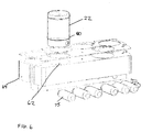
- Figs. 2-7 illustrate one exemplary embodiment of the scent generating system 20 of the present invention.
- the scent generating system 20 has a structural enclosure 48 which has a front panel 50, a base housing 54, and a directional orifice 52.
- the scent generating system 20 can be mounted on adjustable feet 56 to enable the direction of the scent ring to be aimed directly at the nose of the user.
- Removable cartridges 22 containing individual scented chemicals 58, chemical vapors 60, or both, are typically positioned in individual receptacles 62 in linear arrays of two or more such that at least a portion of the delivery assembly 26 is within the manifold 64 (Figs 3, 4, 7, and 8).
- a microprocessor board and/or electrical circuitry 28 are contained within the electronics housing 66 and can be accessed through a conventional data port 68. Thus, a user interface, user inputs, or a network connection can be connected to the microprocessor board 28 through the data port 68.
- the microprocessor board 28 is also electrically coupled to the delivery assembly 26 and the bolus generator 30 to coordinate the release and disbursement of the scent chemical 58, 60.
- FIG. 1 An exemplary storage system 22 is shown in Figs. 1 and 8A to 8D.
- the cartridges can have a valve delivery assembly 26 to control the movement of the scent chemical to the venting chamber 24.
- the cartridge 22 includes an inner chamber 70 which holds the scent chemical 58 (and in some embodiments its vapor 60).
- an air pump 72 can be used to deliver a continuous flow of air, a variable flow of air, or a pulsed flow of air through a conduit assembly 74 (Fig. 1).
- a solenoid regulator valve 75 is electrically coupled to the microprocessor board 28 and impedes the air flow to the cartridges 22.
- At least one of the solenoid regulator valves 75 can be opened in response to an electrical control signal from the microprocessor board 28 and the pressurized flow of air can enter the selected cartridge(s) 22 through an inferior check valve 76.
- the pressurized air will pick up the scent chemical 58, 60 and once the internal pressure of the cartridge chamber 70 reaches a pressure which can open a superior check valve 78, the air flow and scent chemical 58, 60 exit the cartridge through the superior check valve 78 and into the venting chamber 24.
- the scent chemical is stored in a liquid form within a sponge (not shown) in the cartridge. As the pressurized air passes through the sponge, the scent chemical 58 is moved directly to a vapor form as it is moved out of the cartridge.
- Other embodiments of solenoid-type valves are described in commonly owned U.S. Patent No. 5,591,409, the full disclosure of which is incorporated herein by reference.
- both the inferior check valve 76 and superior check valve 78 are preferably one way low-pressure valves that do not allow back flow through the valves.
- a rubber sealing ring 80 circles the scent cartridge 22 so that when the cartridge is inserted into the receptacle 62, a secure seal is created between the cartridge and the receptacle 62.
- the seal prevents air pressure at the base of the cartridge from leaking and further prevents the scent chemical in the cartridges 22 from escaping into the atmosphere and into the venting chamber.
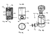
- FIGs. 9A to 9C Another exemplary scent generating system is illustrated in Figs. 9A to 9C.
- This embodiment of the scent generating system 20 includes a plurality of cartridges 22 that are attached to piezo-electric mechanisms that cause the liquid scent chemical to vaporize when an electric charge is applied to the piezo-electric mechanism. The vaporized scent liquid can then be transferred to the venting chamber through a revolving delivery door assembly.
- the cartridge assembly 22 has a piezo electric ultrasonic nebulizer 82 that is continuously in contact with the scent chemical 58. Delivery of an electric charge through the nebulizer sublimates the scent liquid 58 into a gas vapor 60 which rises above the liquid chemical 58. After a sufficient quantity of the scent vapor 60 has been collected, a revolving delivery door 84 can be activated and rotated 180 degrees to receive the vapor 60 in a collection chamber 86. After the vapor 60 has been collected, the door is rotated another 180 degrees such that the measured quantity of scent vapor 60 is moved into the venting chamber 24.
- a signal causes the bolus generator 30 to vibrate in a series of pulses, each of which can force a scent ring 32 of gaseous vapor to be expelled through the orifice 52 at the end of the venting chamber 24.
- the scent rings 32 are directed at the general vicinity of the user's face, and more particularly at the user's nose.
- a piezo-ceramic vibration plate 86 having holes can be attached near the top of the scent chemical 58 to sublimate the scent liquid into a vapor.
- the liquid scent chemical can be continuously in contact with the plate 86, or individual droplets can be applied through a wicking method, an elastomer funnel, or by some other droplet placing means.
- a blister pack 88 can be used to contain the scent chemical. Constant pressure with a moveable roller 90 within a track 92 forces the scent chemical into contact with the piezo electric vibration plate 86. As the scent chemical is vaporized, the moveable roller 90 can be moved upward to maintain contact between the scent chemical and the piezo-electric vibration plate 86. Similar to the embodiment of Fig. 9A, the revolving door assembly 84 or other delivery assemblies can then be used to deliver the vapor into the venting chamber 24.
- the delivery assembly 26 can also include at least one of a vaporizer, nano-pump, or micro-pump, to deliver a vapor or aerosol scent chemical to the venting chamber.
- a vaporizer to deliver a vapor or aerosol scent chemical to the venting chamber.
- Formation of an aerosol creates very small, precisely measured droplets of the scent chemical which optimizes the surface area relative to the volume. Optimization of the size of the scent chemical improves the vaporization rate and the dispersion rate of the scent chemical into the atmosphere.
- Figs. 10A to 10B one exemplary embodiment includes a micro pump 94 and an ultrasonic spray vaporizer 96.
- the scent cartridge 22 contains a rubber sleeve 98 that is filled with scent chemicals.
- the micro pump 94 produces droplets that are typically in the range of 10 microns to 20 microns.
- the droplets are moved into the ultrasonic vaporizer 96 where the droplets are vaporized and sprayed into the venting chamber 24.
- One exemplary micro-metering pump 94 is manufactured by IVEK Corporation, of North Springfield, Vermont.
- a nano scale micro miniature pump (not shown) can be attached to the conduit 100 to create smaller measured droplets that do not need to be vaporized.
- FIGs. 11A and 11B Another exemplary delivery system is illustrated in Figs. 11A and 11B. Because the scent chemical is often a liquid medium, a small concentrated amount of the scent chemical 58 can be expelled in a droplet form 101 from a bubble jet-type cartridge 104. As shown in Figs. 11A and 11B, the bubble jet cartridges 104 can be placed in rows such that the bubble-jet ejector 106 dispenses the scent chemical 58 into the path of a laser beam 108. A laser 109 generated laser beam 108 passes in front of a row of cartridges and can be reflected by a mirror 109 to pass in front of a second or third row of cartridges.
- the cartridges 104 are approximately 2 inches long and have a cross-sectional size of approximately .5 inches x .5 inches. Accordingly, as many as 60 different scents can be contained in 12 inch x 2 inch x 4 inch console.
- One exemplary bubble-jet ejector circuitry and mechanism is manufactured by Hewlett-Packard.
- a micro valve 110 can be used to deliver the droplet 103 to the laser beam 108.
- the droplets 103 produced by the micro valve 110 are typically approximately 10 microns.
- An exemplary micro valve is manufactured by the Lee Company.
- the laser beam 108 can vaporize the droplets 103 into a gas 60 or aerosol that is drawn into the venting chamber 24 with an air current.
- a bolus generator (not shown) can be used to direct a bolus ring 32 of scent chemical at the user through the directional spout 112.
- the cartridge 22 can include a delivery assembly 26 having a capillary tube 114 and sealing gates 116, 118.
- the capillary tube 114 having sealing gates 116, 118 on both ends of the tube allow a measured quantity of the scented vapor to be delivered to the venting chamber (not shown).
- the bottom sealing gate 116 will open to allow a measured amount of scent vapor 60 to enter the capillary tube 114.
- the bottom sealing gate 118 is closed.
- the top sealing gate 118 is opened. When air is blown over the open end of the capillary tube 114, the measured quantity of scent vapor 60 is then drawn into the venting chamber 24.
- venting chamber 24 can be equipped with various anti-contamination means.
- the air can be filtered with filter 115 as it is drawn into the venting chamber so as to remove scent chemicals that are in the atmospheric air (Fig. 9C).
- the venting chamber can also have an exhaust fan 117 and a filter 119 to remove the lingering air and scent chemicals in the venting chambers. The exhaust fan 117 forces the lingering air through the filter 119 and away from the user.
- a permanent or removable absorptive liner 120 can be placed within the scent generating system 20, and particularly within the venting chamber 24 to absorb any residue of the scent chemical.
- the absorptive liner 120 can be made of a chemically treated material that is capable of absorbing at least some of the scent chemicals 58, 60. As shown in Fig. 4, the absorptive liner 120 can be fitted with openings which correspond to the orifice 52, the bolus generator 30 and the cartridges 22.
- the absorptive liner 120 can be made of any scent absorbing material, such as clay, a wood-clay combination, activated carbon, vermiculite, silica gel, zeolite, activated alumina, Gray MatterTM, microsponge, or the like.
- the absorptive liner 120 can cover the entire inner wall of the venting chamber or it can only cover a selected portion of the venting chamber.
- the absorptive liner can be composed of smaller pieces and placed in a variety of other strategic places, such as the conduits.
- a power supply 122 (Fig. 1) can be used to apply a like electric charge to the inner walls of the venting chamber 24 and to the scented chemical 58, 60.
- the like charge causes the scent chemicals 58, 60 to be repelled by the venting chamber 24 and limits the adherence of the scent chemical 58, 60 to the inner wall.
- power supply 122 is typically supplied to the scent delivery system 20 through a power cord 124 which attaches to a power outlet at the back of the housing.
- the power supply 122 can also be used to power the pumps, microprocessor board, bolus generator, and the like (Fig. 1).
- some embodiments of the scent generating device will have a directional cylinder 124 at the end of the venting chamber 24 that can be adjusted, either manually or automatically to cause the bolus rings 32 to be aimed at the nose of the user.
- the automatic aiming mechanism 127 is an electric potentiometer that moves the directional cylinder 124 in response to a signal from a position or motion sensor 126. It will be appreciated however, that the automatic aiming mechanism 127 may move in response to a video imaging camera, an infrared imager a camera, or other means of determining the position of the user and the user's nose.
- the motion sensor can be used to simply determine that a person has entered the general vicinity. For example, if the motion sensor 126 senses a person walking near the device associated with the scent generating system, the motion sensor can send a signal to the microprocessor board to deliver a scent to try to "entice” the potential user to approach the video device.
Abstract
Description
- The present invention relates generally to the delivery of chemicals, and more particularly to methods and systems for the controlled delivery of scented aerosols to a localized target.
- The addition of scent to entertainment or other activities connected with data or information dissemination is known. Increased use of computers, game consoles, internet appliances, and other individual oriented devices have brought about an increased desire to synchronize the delivery of scents in conjunction with these and other automated activities. The human olfactory senses are very sensitive and the accuracy and consistency of the scent is critical. A major criteria of success is the ability to deliver scents to the user accurately, quickly, and cleanly without impacting other people in the vicinity.
- Most conventional systems involve use of a fan that blows scented chemicals in the direction of the target user. Unfortunately, the conventional devices lack the means to control the delivery of the scent to the specific target and often fill the entire room with large amounts of the scent chemical. Because of the nature of the scented oils and chemicals, it is often difficult to remove the of scent chemicals prior to the introduction of a new scent. Consequently, the ensuing deliveries of different scents are often contaminated with the lingering scent of the previously delivered scent.
- DE-A-4033076 discloses a scent delivery system wherein a sample of scent is ejected from a blow pipe.
- Therefore, as can be appreciated, there is a need of systems and methods which can provide an individualized scent experience while reducing the level of contamination of new scents with the lingering scent from the previous deliveries.
- The present invention generally provides systems and methods for delivering a controlled amount of scent to a target user. Such methods and systems will preferably provide carefully direct boluses or streams of scent(s) to a single or small group of individual(s) so as to avoid cross-contamination of scents with other persons and other locations.
- The present invention preferably delivers the bolus of scent as an air ring. The scented air ring moves through the air between the scent generating device directly to the user as a cohesive unit of air. This phenomenon is similar to a "smoke ring" exhaled by a smoker. The scent ring can be directed with accuracy to a localized target as small as the nose of a single user, such that the entire dosage can be delivered to only the user's direct vicinity. Such targeted delivery minimizes the amount of scent that must be delivered to achieve a desired level of scenting at the target location. Consequently, the amount of scent that must be removed or dissipated from the user's area is also reduced and the cross-contamination of the different scents is reduced.
- Systems of the present invention typically have a plurality of storage chambers coupled to a venting chamber. An electrical signal generator and bolus generator, such as a vibratable diaphragm or an audio speaker, can be used to create a pulse to deliver the scent chemical. The electrical signal generator can be activated by mechanical means, an electronic signal embedded in a recorded media, an electrical signal generated by an interactive program, or the like. In most implementations, the electrical signal generator and bolus generator impart a rapid increase of air pressure in the venting chamber holding the scent. The delivery of the scent ring from the present invention is typically through an orifice or opening in the venting chamber. In most embodiments, the orifice can be aimed towards the direct vicinity of a user's nose, so as to maximize the scent experience to the target user. The size and speed of travel of the scent ring can be adjusted for different circumstances by changing the frequency and number of pulses, changing the size of the opening, the number of openings, or the like.
- In another aspect of the present invention, a scent generating system can be configured to reduce the level of contamination of a new scent from the lingering scent of the previously delivered scent chemical. In some embodiments, an exhaust fan and air filter are used to remove the lingering scented air in the venting chambers. Optionally, air can be further be filtered while being drawn into the chamber to reduce the amount of contaminated air drawn into the venting chamber. Therefore, newly generated scents will contain only a limited amount of unwanted contaminants.
- Because it is difficult to remove all of the scents retained in the venting chamber, some implementations of the present invention can have an absorptive material, such as an absorptive clay, positioned over at least a portion of the venting chamber. The absorptive material attracts the scent chemicals and absorbs them with a trapping effect so as to inhibit contamination of subsequent scent chemicals moved through the venting chamber.
- As an alternative to the absorptive material, another method that can be used to reduce the contamination of subsequent scents is to impart a similar electrical charge to both the venting chamber and the scent chemicals. The two similarly charged elements repel each other and limit the adherence of the scent to the venting chamber.
- The individual scent chemicals are each typically contained in a separate cartridge that is inserted into a receptacle inside the enclosure. At least one scent chemical is selected from the plurality of scent cartridges and it is moved to the venting chamber through a delivery system. In one implementation, the delivery system has a small pump that imparts a steady pressure into one opening of the cartridge. The steady pressure enters through a first one way check valve and creates an increase air pressure in the interior of the cartridge. A second check valve opens and allows scented air to be emitted into the venting chamber for delivery to the user. In most embodiments, an electrical signal controls the opening of a regulator valve that allows the flow of the air pressure through the check valves. In order to add further precautionary measures to minimize scent leakage, the cartridges can have a sealing o-ring encircling the outside which provides a frictionally adhered connection between the cartridge and the interior walls of the holding receptacle.
- After being moved from the cartridges, the scent chemical, if in liquid form, may be vaporized using a variety of methods, such as flowing the scent chemical through a micro-pump or a nano-pump, saturating a porous membrane, or vaporizing a liquid using an electrically activated piezo-ceramic plate, a laser, or the like.
- The control of the scent generating system is typically through the use of microprocessor circuity which controls the timing and frequency of the emission. The control circuity is typically linked to programmable electronic activation means through standard communication links, such as cables, wireless connection, infrared, radio, or the like.
- In another aspect, the present invention provides a system for delivering scent chemicals. The system has a venting chamber having an orifice. A plurality of cartridges hold the individual chemicals. At least one of the cartridge can be activated to release its scent chemicals to the venting chamber. A bolus generator assembly is coupled to the venting chamber such that the bolus generator assembly delivers a pulse of air which forces a ring bolus of the chemical through the orifice in the venting chamber.
- In another aspect, the present invention provides a system for delivering a scent chemical to a localized target. The system comprises a venting chamber having an orifice. A plurality of storage means store individual scent chemicals. The storage means control the release of at least one selected scent chemical into the venting chamber. Pulse means deliver a controlled air pulse to the scent chemical within the venting chamber to expel the scent chemical through the orifice in a shape of a ring bolus.
- In still another aspect, the present invention provides a system for delivering scent chemicals to a localized target. The system has a venting chamber with an opening. The venting chamber is adapted to receive stream(s) of scent chemicals. A dispersion mechanism is in communication with the venting chamber such that the dispersion mechanism moves the scent chemical through the venting chamber. An absorptive liner is formed over at least a portion of the venting chamber to absorb the scent chemical remaining in the venting chamber after the scent chemical has been moved through the venting chamber.
- In yet another aspect, the present invention provides a system for dispensing a scent. The system has means for electrically charging a scent chemical. A venting chamber for receiving the electrically charged scent chemical has a like-charge such that the venting chamber repels the scent chemical and lessens the contamination from the scent chemical. A delivery mechanism is configured to force the scent chemical through an opening in the venting chamber.
- In another aspect, the present invention provides a method. A scent chemical is selected from a plurality of scent chemicals. A scent ring is formed and directed toward a user.
- In still another aspect, the present invention provides a method for a localized delivery of scents. A scent chemical is selected from a plurality of scent chemicals. An air pulse is generated to controllably disperse the vapor from the venting chamber in the form of a ring bolus.
- In yet another aspect, the present invention provides a method. A first scent chemical is moved through a venting chamber. At least a portion of the residue of the first scent chemical within the venting chamber is absorbed so as to inhibit the contamination of a second scent chemical moved through the venting chamber.
- In another aspect, the present invention provides a method. An electrically charged scent chemical is moved into a venting chamber. A like charge is provided to the venting chamber such that the like-charged venting chamber substantially repels the scent chemical so as to inhibit the scent chemical from adhering to the wall.
- Other objects, features, and advantages of the present invention will become apparent upon consideration of the following detailed description and the accompanying drawings, in which like reference designations represent like features throughout the figures.
-
- Fig. 1 is a simplified block diagram of one embodiment incorporating the present invention;
- Fig. 2 is an isometric view of a scent generating system according to the present invention;
- Fig. 3 is an isometric view of the system of Fig. 2 with the front panel removed;
- Fig. 4 is an exploded isometric view of the system of Fig. 2;
- Fig. 5 is an exploded rear isometric view of the system of Fig. 2;
- Fig. 6 is an exploded view of the cartridge manifold assembly;
- Fig. 7 is a cross-sectional view of the system of Fig. 2;
- Fig. 8A is a cross sectional view of the cartridge;
- Fig. 8B is a side view of the cartridge;
- Fig. 8C is a top view of the cartridge;
- Fig. 8D is an exploded perspective view of the cartridge;
- Fig. 9A is a cross sectional view of a cartridge having a piezo electric mechanism;
- Fig. 9B is a cross sectional view of another embodiment of a cartridge having a piezo electric mechanism;
- Fig. 9C is a cross sectional view of the scent generating system having the piezo electric mechanism;
- Fig. 10A is a cross sectional view of a system having a micro pump and a vaporizer;
- Fig. 10B is an elevational view of the system of Fig. 10A;
- Fig. 11A is a cross sectional view showing the bubble jet ejector cartridges and a laser beam;
- Fig. 11B shows a droplet that is ejected from a bubble jet ejector;
- Fig. 11C shows a micro valve of the present invention;
- Fig. 11D is a perspective view of a system of the present invention; and
- Fig 12 shows a cartridge having a capillary delivery system.
- Fig. 1 shows a simplified block diagram of the components of a
scent generating system 20 according to the present invention. The system generally includes astorage system 22, such as cartridges or reservoirs, that store individual scent chemicals. Thestorage system 22 is coupled to ascent venting chamber 24 through adelivery assembly 26. Thedelivery assembly 26 typically has some combination of valves, conduits, pumps, and vaporizers and can be configured to meter and control the flow of the scent chemicals from thecartridges 22 to the ventingchamber 24. A signal from acontrol system 28 activates thedelivery assembly 26 to move the selected scent chemical(s) from the selected cartridge(s) 22 to the ventingchamber 24. Once the selected scent chemical(s) have been transferred to the ventingchamber 26, abolus generator 30, such as a vibratable diaphragm or a speaker, is activated by a signal generator (not shown) to generate an air pulse. The air pulse delivers the scent chemical through an orifice (not shown) in the ventingchamber 24 and creates a ring bolus orscent ring 32 which can be controllably directed toward an individualized user. - An operator or user typically interacts with the scent generating system through a
user interface 34 anduser inputs 36.User inputs 36, such as buttons, levers, switches, joysticks, a keyboard, or the like, deliver a control signal through aCPU 38 to amicroprocessor board 28 in thescent generating system 20. In most embodiments, the control signal can be transmitted through aconnection interface 42 such ascable 44 orwireless connections 46 to activate the delivery of the scent chemical. As shown in Fig. 1, the user interface can be attached directly to the scent generating system or can be remotely connected to the scent generating system. It should be appreciated, however, that in other embodiments of the present invention, the scent generating system can be activated remotely through a network, such as the internet. In such embodiments, the user that receives the delivered scent would not have to interface directly with theinterface 34 oruser inputs 36. - The particular selection of the scent chemical and the sequence of the various selections over a period of time is controlled by the
microprocessor board 28 and theCPU 38. The microprocessor may be pre-programmed to provide a prearranged sequence of scent chemicals when a pre-recorded presentation is playing, or the microprocessor board may be interactive and the scent delivery pattern will depend on the specific user inputs. - Figs. 2-7 illustrate one exemplary embodiment of the
scent generating system 20 of the present invention. Thescent generating system 20 has astructural enclosure 48 which has afront panel 50, abase housing 54, and adirectional orifice 52. Thescent generating system 20 can be mounted onadjustable feet 56 to enable the direction of the scent ring to be aimed directly at the nose of the user.Removable cartridges 22 containing individualscented chemicals 58,chemical vapors 60, or both, are typically positioned inindividual receptacles 62 in linear arrays of two or more such that at least a portion of thedelivery assembly 26 is within the manifold 64 (Figs 3, 4, 7, and 8). A microprocessor board and/orelectrical circuitry 28 are contained within theelectronics housing 66 and can be accessed through aconventional data port 68. Thus, a user interface, user inputs, or a network connection can be connected to themicroprocessor board 28 through thedata port 68. Themicroprocessor board 28 is also electrically coupled to thedelivery assembly 26 and thebolus generator 30 to coordinate the release and disbursement of thescent chemical - An
exemplary storage system 22 is shown in Figs. 1 and 8A to 8D. The cartridges can have avalve delivery assembly 26 to control the movement of the scent chemical to the ventingchamber 24. Thecartridge 22 includes aninner chamber 70 which holds the scent chemical 58 (and in some embodiments its vapor 60). In most embodiments, anair pump 72 can be used to deliver a continuous flow of air, a variable flow of air, or a pulsed flow of air through a conduit assembly 74 (Fig. 1). Asolenoid regulator valve 75 is electrically coupled to themicroprocessor board 28 and impedes the air flow to thecartridges 22. At least one of thesolenoid regulator valves 75 can be opened in response to an electrical control signal from themicroprocessor board 28 and the pressurized flow of air can enter the selected cartridge(s) 22 through aninferior check valve 76. After entering thechamber 70, the pressurized air will pick up thescent chemical cartridge chamber 70 reaches a pressure which can open asuperior check valve 78, the air flow andscent chemical superior check valve 78 and into the ventingchamber 24. In one specific configuration, the scent chemical is stored in a liquid form within a sponge (not shown) in the cartridge. As the pressurized air passes through the sponge, thescent chemical 58 is moved directly to a vapor form as it is moved out of the cartridge. Other embodiments of solenoid-type valves are described in commonly owned U.S. Patent No. 5,591,409, the full disclosure of which is incorporated herein by reference. - When no air is flowing through the
check valves scent chemical inferior check valve 76 andsuperior check valve 78 are preferably one way low-pressure valves that do not allow back flow through the valves. - As shown in Figs. 6, 8B, and 8D, in some implementations a
rubber sealing ring 80 circles thescent cartridge 22 so that when the cartridge is inserted into thereceptacle 62, a secure seal is created between the cartridge and thereceptacle 62. The seal prevents air pressure at the base of the cartridge from leaking and further prevents the scent chemical in thecartridges 22 from escaping into the atmosphere and into the venting chamber. - Another exemplary scent generating system is illustrated in Figs. 9A to 9C. This embodiment of the
scent generating system 20 includes a plurality ofcartridges 22 that are attached to piezo-electric mechanisms that cause the liquid scent chemical to vaporize when an electric charge is applied to the piezo-electric mechanism. The vaporized scent liquid can then be transferred to the venting chamber through a revolving delivery door assembly. - As shown in the embodiment of Figs. 9A and 9C, the
cartridge assembly 22 has a piezo electricultrasonic nebulizer 82 that is continuously in contact with thescent chemical 58. Delivery of an electric charge through the nebulizer sublimates thescent liquid 58 into agas vapor 60 which rises above theliquid chemical 58. After a sufficient quantity of thescent vapor 60 has been collected, a revolvingdelivery door 84 can be activated and rotated 180 degrees to receive thevapor 60 in acollection chamber 86. After thevapor 60 has been collected, the door is rotated another 180 degrees such that the measured quantity ofscent vapor 60 is moved into the ventingchamber 24. As above, once thescent vapor 60 has been delivered into the ventingchamber 24, a signal causes thebolus generator 30 to vibrate in a series of pulses, each of which can force ascent ring 32 of gaseous vapor to be expelled through theorifice 52 at the end of the ventingchamber 24. The scent rings 32 are directed at the general vicinity of the user's face, and more particularly at the user's nose. - In an alternative embodiment shown in Fig. 9B, a piezo-
ceramic vibration plate 86 having holes can be attached near the top of thescent chemical 58 to sublimate the scent liquid into a vapor. The liquid scent chemical can be continuously in contact with theplate 86, or individual droplets can be applied through a wicking method, an elastomer funnel, or by some other droplet placing means. In the specific implementation shown, ablister pack 88 can be used to contain the scent chemical. Constant pressure with amoveable roller 90 within atrack 92 forces the scent chemical into contact with the piezoelectric vibration plate 86. As the scent chemical is vaporized, themoveable roller 90 can be moved upward to maintain contact between the scent chemical and the piezo-electric vibration plate 86. Similar to the embodiment of Fig. 9A, the revolvingdoor assembly 84 or other delivery assemblies can then be used to deliver the vapor into the ventingchamber 24. - In yet other embodiment of the present invention, the
delivery assembly 26 can also include at least one of a vaporizer, nano-pump, or micro-pump, to deliver a vapor or aerosol scent chemical to the venting chamber. Formation of an aerosol creates very small, precisely measured droplets of the scent chemical which optimizes the surface area relative to the volume. Optimization of the size of the scent chemical improves the vaporization rate and the dispersion rate of the scent chemical into the atmosphere. Referring now to Figs. 10A to 10B, one exemplary embodiment includes amicro pump 94 and anultrasonic spray vaporizer 96. In the embodiment shown, thescent cartridge 22 contains arubber sleeve 98 that is filled with scent chemicals. Pressure within thecartridge 22 on therubber sleeve 98 is sufficient to move the scent chemical through aconduit 100 into themicro pump 94. Themicro pump 94 produces droplets that are typically in the range of 10 microns to 20 microns. The droplets are moved into theultrasonic vaporizer 96 where the droplets are vaporized and sprayed into the ventingchamber 24. One exemplarymicro-metering pump 94 is manufactured by IVEK Corporation, of North Springfield, Vermont. As an alternative to themicro pump 94 andvaporizer 96, a nano scale micro miniature pump (not shown) can be attached to theconduit 100 to create smaller measured droplets that do not need to be vaporized. - Another exemplary delivery system is illustrated in Figs. 11A and 11B. Because the scent chemical is often a liquid medium, a small concentrated amount of the
scent chemical 58 can be expelled in adroplet form 101 from a bubble jet-type cartridge 104. As shown in Figs. 11A and 11B, thebubble jet cartridges 104 can be placed in rows such that the bubble-jet ejector 106 dispenses thescent chemical 58 into the path of alaser beam 108. Alaser 109 generatedlaser beam 108 passes in front of a row of cartridges and can be reflected by amirror 109 to pass in front of a second or third row of cartridges. In a specific implementation, thecartridges 104 are approximately 2 inches long and have a cross-sectional size of approximately .5 inches x .5 inches. Accordingly, as many as 60 different scents can be contained in 12 inch x 2 inch x 4 inch console. One exemplary bubble-jet ejector circuitry and mechanism is manufactured by Hewlett-Packard. - An alternative embodiment to the bubble jet ejector is shown in Fig. 11C. Instead of a bubble jet ejector, a
micro valve 110 can be used to deliver the droplet 103 to thelaser beam 108. The droplets 103 produced by themicro valve 110 are typically approximately 10 microns. An exemplary micro valve is manufactured by the Lee Company. - In both the bubble jet and micro valve embodiments, the
laser beam 108 can vaporize the droplets 103 into agas 60 or aerosol that is drawn into the ventingchamber 24 with an air current. As shown in 11D, a bolus generator (not shown) can be used to direct abolus ring 32 of scent chemical at the user through thedirectional spout 112. - In still another embodiment, the
cartridge 22 can include adelivery assembly 26 having acapillary tube 114 and sealinggates 116, 118. As shown in Fig. 12 thecapillary tube 114 having sealinggates 116, 118 on both ends of the tube allow a measured quantity of the scented vapor to be delivered to the venting chamber (not shown). The bottom sealing gate 116 will open to allow a measured amount ofscent vapor 60 to enter thecapillary tube 114. Once thecapillary tube 114 has been filled, thebottom sealing gate 118 is closed. To release the vapor into the ventingchamber 24 thetop sealing gate 118 is opened. When air is blown over the open end of thecapillary tube 114, the measured quantity ofscent vapor 60 is then drawn into the ventingchamber 24. - Another aspect of the present invention is the ability to reduce contamination of subsequently delivered scents. In order to reduce scent chemical contamination the venting
chamber 24 can be equipped with various anti-contamination means. In one embodiment, the air can be filtered withfilter 115 as it is drawn into the venting chamber so as to remove scent chemicals that are in the atmospheric air (Fig. 9C). As shown in Figs. 3 to 5, the venting chamber can also have anexhaust fan 117 and afilter 119 to remove the lingering air and scent chemicals in the venting chambers. Theexhaust fan 117 forces the lingering air through thefilter 119 and away from the user. - Optionally, a permanent or removable
absorptive liner 120 can be placed within thescent generating system 20, and particularly within the ventingchamber 24 to absorb any residue of the scent chemical. Theabsorptive liner 120 can be made of a chemically treated material that is capable of absorbing at least some of thescent chemicals absorptive liner 120 can be fitted with openings which correspond to theorifice 52, thebolus generator 30 and thecartridges 22. Theabsorptive liner 120 can be made of any scent absorbing material, such as clay, a wood-clay combination, activated carbon, vermiculite, silica gel, zeolite, activated alumina, Gray Matter™, microsponge, or the like. Naturally, it will be appreciated that theabsorptive liner 120 can cover the entire inner wall of the venting chamber or it can only cover a selected portion of the venting chamber. For example, the absorptive liner can be composed of smaller pieces and placed in a variety of other strategic places, such as the conduits. - As an alternative to the absorptive liner, a power supply 122 (Fig. 1) can be used to apply a like electric charge to the inner walls of the venting
chamber 24 and to thescented chemical scent chemicals chamber 24 and limits the adherence of thescent chemical power supply 122 is typically supplied to thescent delivery system 20 through apower cord 124 which attaches to a power outlet at the back of the housing. In addition to creating the electric charge, thepower supply 122 can also be used to power the pumps, microprocessor board, bolus generator, and the like (Fig. 1). - Referring again to Figs. 10A and 10B, some embodiments of the scent generating device will have a
directional cylinder 124 at the end of the ventingchamber 24 that can be adjusted, either manually or automatically to cause the bolus rings 32 to be aimed at the nose of the user. In the embodiment shown in Figs. 10A and 10B the automatic aiming mechanism 127, is an electric potentiometer that moves thedirectional cylinder 124 in response to a signal from a position ormotion sensor 126. It will be appreciated however, that the automatic aiming mechanism 127 may move in response to a video imaging camera, an infrared imager a camera, or other means of determining the position of the user and the user's nose. - In addition to using the position or
motion sensor 126 to track a person's movement, the motion sensor can be used to simply determine that a person has entered the general vicinity. For example, if themotion sensor 126 senses a person walking near the device associated with the scent generating system, the motion sensor can send a signal to the microprocessor board to deliver a scent to try to "entice" the potential user to approach the video device. - This description of embodiments of the invention is presented for the purposes of illustration and description. It is not intended to be exhaustive or to limit the invention to the precise form described, and many modifications and variations are possible in light of the description above. The embodiments were chosen and described in order to best explain the principles of the invention and its practical applications. This description of embodiments will enable others skilled in the art to best utilize and practice the invention in various embodiments and with various modifications as are suited to the particular use contemplated. It is intended that the scope of the invention be defined by the following claims.
Claims (27)
- A system for delivering a scent chemical, the system comprising:a venting chamber (24) having an orifice (52);a cartridge assembly (22) which holds a scent chemical, wherein the cartridge assembly releases its scent chemical into the venting chamber (24); anda bolus generator assembly (30) coupled to the venting chamber, wherein the bolus generator assembly delivers a controlled pulse of air which forces a ring bolus (32) of the scent chemical out of the orifice.
- The system of claim 1 wherein an interior portion of the venting chamber is at least partially lined with a scent absorbing material (120).
- The system of claim 2 wherein the scent absorbing material comprises clay, vermiculite, silica gel, zeolite, activated alumina, or a wood-clay combination.
- The system of any preceding claim further comprising an electrical power supply (122) which provides an electrostatic charge to both an interior portion of the venting chamber and the scent chemical such that the interior portion of the venting chamber substantially repels the scent chemical so as to inhibit the scent chemical from adhering to the venting chamber.
- The system of any preceding claim wherein the cartridge delivers the scent chemical to the venting chamber as a vapor or aerosol.
- The system of any preceding claim wherein the orifice is adjustable in diameter.
- The system of any preceding claim further comprising a ventilation fan (117) and a filter (119), wherein the ventilation fan and filter remove at least a portion of the scent chemical remaining in the venting chamber, and wherein the ventilation fan is directed away from the user.
- The system of any preceding claim wherein the bolus generator assembly is a diaphragm or an audio speaker.
- The system of claim 8 wherein the bolus generator assembly is coupled to a signal generator, wherein the signal generator provides waveform signal to create the pulse of air.
- The system of any preceding claim further comprising a delivery assembly (26) which is coupled to the cartridge assembly, wherein the delivery assembly moves a measured amount of the scent chemical from the cartridge assembly to the venting chamber.
- The system of any of claims 1 to 10, further comprising
a position or motion sensor (126); and
an automatic aiming mechanism (127) for directing the ring bolus in response to a signal from the position or motion sensor. - The system of claim 11, wherein the automatic aiming mechanism is an electric potentiometer.
- The system of any of claims 1 to 12, further comprising
means of determining the position of a target user; and
an automatic aiming mechanism for directing the ring bolus toward the target user. - The system of claim 13, wherein the means for determining the position of the target user is a video imaging camera.
- A method of delivering a scent chemical using a system according to any of Claims 1 to 10, the method comprising:transferring a scent chemical from a cartridge assembly (22) to a venting chamber (24); forming a scent ring; anddirecting the scent ring toward a user.
- The method of claim 15 further comprising metering the scent chemical.
- The method of claim 15 or 16 wherein directing is carried out with a vibratable diaphragm or an audio speaker.
- The method of any of claims 15 to 17 further comprising inhibiting the contamination of the venting chamber.
- The method of any of claims 15 to 18 comprising directing the scent chemical from the cartridge assembly to the venting chamber through check valves.
- The method of any of claims 15 to 19 wherein transferring comprises vaporizing the scent chemical into a gas or an aerosol.
- The method of any of claims 15 to 20 further comprising aiming the scent chemical at a general vicinity of a user's nose.
- The method of any of claims 15 to 21 further comprising selecting the scent chemical from a plurality of scent chemicals.
- The method of any of claims 15 to 22 further comprising sensing the presence of the user.
- The method of any of claims 15 to 23, wherein directing the scent ring toward the user comprises tracking the user's movement.
- The method of claim 24, wherein tracking the user's movement comprises the use of a video imaging camera.
- The method of any of claims 11 to 25 wherein the scent chemical is selected from a plurality of scent chemicals.
- The system of any of claims 1 to 14 wherein the system comprises a plurality of cartridge assemblies and wherein each of the cartridge assemblies holds an individual scent chemical.
Applications Claiming Priority (3)
| Application Number | Priority Date | Filing Date | Title |
|---|---|---|---|
| US12397099P | 1999-03-12 | 1999-03-12 | |
| US123970P | 1999-03-12 | ||
| PCT/US2000/006490 WO2000053301A1 (en) | 1999-03-12 | 2000-03-10 | Methods and apparatus for localized delivery of scented aerosols |
Publications (3)
| Publication Number | Publication Date |
|---|---|
| EP1169114A1 EP1169114A1 (en) | 2002-01-09 |
| EP1169114A4 EP1169114A4 (en) | 2002-05-29 |
| EP1169114B1 true EP1169114B1 (en) | 2006-02-08 |
Family
ID=22412012
Family Applications (1)
| Application Number | Title | Priority Date | Filing Date |
|---|---|---|---|
| EP00916283A Expired - Lifetime EP1169114B1 (en) | 1999-03-12 | 2000-03-10 | Methods and apparatus for localized delivery of scented aerosols |
Country Status (8)
| Country | Link |
|---|---|
| US (4) | US6357726B1 (en) |
| EP (1) | EP1169114B1 (en) |
| JP (1) | JP2002537961A (en) |
| AT (1) | ATE317290T1 (en) |
| AU (1) | AU3741100A (en) |
| DE (1) | DE60025914T2 (en) |
| HK (1) | HK1043690A1 (en) |
| WO (1) | WO2000053301A1 (en) |
Families Citing this family (152)
| Publication number | Priority date | Publication date | Assignee | Title |
|---|---|---|---|---|
| EP1169114B1 (en) * | 1999-03-12 | 2006-02-08 | Microscent, LLC. | Methods and apparatus for localized delivery of scented aerosols |
| FR2795348B1 (en) * | 1999-06-22 | 2001-09-14 | Osmooze Sa | PROGRAMMABLE DEVICE FOR SCATTERING ODOR PICS |
| US6541052B1 (en) * | 1999-07-01 | 2003-04-01 | Peter J. Rohleder | Methods and apparatus for sampling product aromas |
| US6602475B1 (en) | 2000-06-14 | 2003-08-05 | Multisen Technology, Inc. | Multimedia and scent storage medium and playback apparatus having electrostatic scent release |
| US6654664B1 (en) | 2000-06-14 | 2003-11-25 | Multisen Technology, Inc. | Multimedia and scent storage medium and playback apparatus |
| US8061628B1 (en) | 2000-07-27 | 2011-11-22 | The Procter & Gamble Company | Systems and devices for emitting volatile compositions |
| US20020068010A1 (en) * | 2000-12-04 | 2002-06-06 | The Procter & Gamble Company | Articles, systems, and methods for dispensing volatile materials into the environment |
| US20040033171A1 (en) * | 2000-07-27 | 2004-02-19 | The Procter & Gamble Company | Systems and devices for emitting volatile compositions |
| US6581915B2 (en) * | 2000-07-27 | 2003-06-24 | The Procter & Gamble Company | Dispensing device for dispensing scents |
| US20040028551A1 (en) * | 2000-07-27 | 2004-02-12 | Kvietok Frank Andrej | Methods for emitting volatile compositions |
| US6383165B1 (en) * | 2000-09-22 | 2002-05-07 | Henri J. R. Maget | System for achieving a controlled low emission rate for small volumes of liquid solutions |
| US20030206834A1 (en) * | 2000-11-16 | 2003-11-06 | Chiao Dahshiarn | Replaceable scent and multimedia storage medium for use with a playback apparatus having electrostatic scents release |
| US7691336B2 (en) * | 2000-12-05 | 2010-04-06 | The Procter & Gamble Company | Devices and systems for dispensing volatile materials |
| US20040007787A1 (en) * | 2000-12-05 | 2004-01-15 | The Procter & Gamble Company | Articles, systems, and methods for dispensing volatile materials |
| US8178773B2 (en) | 2001-08-16 | 2012-05-15 | Beamz Interaction, Inc. | System and methods for the creation and performance of enriched musical composition |
| GB0123851D0 (en) * | 2001-10-04 | 2001-11-28 | Pankhurst Design & Development | Dispersing fragrances |
| US20030164557A1 (en) * | 2002-01-22 | 2003-09-04 | Caleb Chung | Interactive, automated aroma diffuser with interface to external device |
| DE10204496A1 (en) * | 2002-02-04 | 2003-08-21 | Msa Auer Gmbh | Device for dosing gaseous and / or vaporous substances |
| GB0206806D0 (en) * | 2002-03-22 | 2002-05-01 | Nu Light Systems Ltd | Air scenting apparatus |
| DE10213889A1 (en) * | 2002-03-27 | 2003-10-23 | Weigl Lidia | Air fresheners and methods for air freshening in rooms |
| US7203417B2 (en) * | 2002-04-08 | 2007-04-10 | Joseph Manne | Portable scent delivery device |
| US7562399B2 (en) * | 2002-04-10 | 2009-07-21 | Arichell Technologies | Toilet flusher for water tanks with novel valves and dispensers |
| US7665673B2 (en) * | 2002-04-19 | 2010-02-23 | Hagleitner Hygiene International Gmbh | Method and apparatus for spraying portions of an air-improving substance |
| ATE413891T1 (en) * | 2002-04-19 | 2008-11-15 | Hagleitner Hygiene Internat Gm | METHOD FOR SPRAYING PORTIONS OF AN AIR IMPROVEMENT SUBSTANCE |
| WO2003098971A1 (en) | 2002-05-13 | 2003-11-27 | S.C. Johnson & Son, Inc. | Coordinated emission of fragrance, light, and sound |
| GB0211354D0 (en) * | 2002-05-17 | 2002-06-26 | Surface Innovations Ltd | Atomisation of a precursor into an excitation medium for coating a remote substrate |
| GB0212848D0 (en) * | 2002-06-01 | 2002-07-17 | Surface Innovations Ltd | Introduction of liquid/solid slurry into an exciting medium |
| US20040204043A1 (en) * | 2002-08-29 | 2004-10-14 | Hwai-Ming Wang | Information apparatus with interactive scent interface |
| AU2003291510B2 (en) | 2002-11-08 | 2009-05-28 | S.C. Johnson & Son, Inc. | Dispensing of multiple volatile substances |
| US7469844B2 (en) * | 2002-11-08 | 2008-12-30 | S.C. Johnson & Son, Inc. | Diffusion device and method of diffusing |
| WO2004071541A1 (en) * | 2003-02-06 | 2004-08-26 | S. C. Johnson & Son Inc. | Vortex generator for dispensing actives |
| MXPA05008369A (en) | 2003-02-07 | 2005-11-04 | Johnson & Son Inc S C | Diffuser with light emitting diode nightlight. |
| US20040235570A1 (en) * | 2003-05-22 | 2004-11-25 | Rothschild Wayne H. | Gaming machine with personal climate Control |
| JP4647897B2 (en) * | 2003-09-26 | 2011-03-09 | 有限会社酸京クラウド | Air gun generator |
| WO2005030276A1 (en) | 2003-09-26 | 2005-04-07 | Scentainment Ltd. | Controller and cartridge unit for providing fragrances |
| US20050191269A1 (en) * | 2003-12-09 | 2005-09-01 | Glassco Anton D. | Automatic air fragrance unit |
| US20050127206A1 (en) * | 2003-12-10 | 2005-06-16 | Xerox Corporation | Device and system for dispensing fluids into the atmosphere |
| US20050129568A1 (en) * | 2003-12-10 | 2005-06-16 | Xerox Corporation | Environmental system including a micromechanical dispensing device |
| US20050130747A1 (en) * | 2003-12-10 | 2005-06-16 | Xerox Corporation | Video game system including a micromechanical dispensing device |
| US20060120080A1 (en) * | 2004-02-03 | 2006-06-08 | Gene Sipinski | Control and an integrated circuit for a multisensory apparatus |
| US7824627B2 (en) | 2004-02-03 | 2010-11-02 | S.C. Johnson & Son, Inc. | Active material and light emitting device |
| KR101283352B1 (en) * | 2004-02-03 | 2013-07-08 | 에스.씨. 존슨 앤드 선, 인코포레이티드 | Device providing coordinated emission of light and volatile active |
| US7350720B2 (en) * | 2004-02-03 | 2008-04-01 | S.C. Johnson & Son, Inc. | Active material emitting device |
| US20070235555A1 (en) * | 2006-04-11 | 2007-10-11 | Helf Thomas A | Electronic aerosol device |
| US7154579B2 (en) * | 2004-03-03 | 2006-12-26 | Selander Raymond K | Fragrance delivery for multimedia systems |
| US20070023540A1 (en) * | 2004-03-03 | 2007-02-01 | Selander Raymond K | Fragrance Delivery for Multimedia Systems |
| US20050195366A1 (en) * | 2004-03-03 | 2005-09-08 | Selander Raymond K. | Fragrance delivery for multimedia systems |
| US20080035765A1 (en) * | 2004-04-20 | 2008-02-14 | Xerox Corporation | Environmental system including a micromechanical dispensing device |
| KR200359944Y1 (en) * | 2004-05-06 | 2004-08-27 | 김영오 | Wall-mounted ultrasonic humidifier |
| ITUD20040104A1 (en) * | 2004-05-21 | 2004-08-21 | M Box Srl | METHOD AND APPARATUS FOR THE DIFFUSION OF OLFACTORY SUBSTANCES |
| ATE376843T1 (en) * | 2004-06-30 | 2007-11-15 | Johnson & Son Inc S C | ELECTROMECHANICAL DEVICE FOR DISPENSING VOLATILE SUBSTANCES WITH SINGLE DISPENSING MECHANISM AND CASSETTE FOR HOLDING SEVERAL CONTAINERS |
| US7389943B2 (en) * | 2004-06-30 | 2008-06-24 | S.C. Johnson & Son, Inc. | Electromechanical apparatus for dispensing volatile substances with single dispensing mechanism and cartridge for holding multiple receptacles |
| US20060074742A1 (en) * | 2004-09-27 | 2006-04-06 | Carmine Santandrea | Scent delivery devices and methods |
| US8061562B2 (en) | 2004-10-12 | 2011-11-22 | S.C. Johnson & Son, Inc. | Compact spray device |
| ZA200703607B (en) * | 2004-10-12 | 2009-01-28 | Johnson & Son Inc S C | Compact spray device |
| US20060113687A1 (en) * | 2004-11-29 | 2006-06-01 | Mark Castellano | Remote control HVAC air freshener |
| WO2006059426A1 (en) * | 2004-12-02 | 2006-06-08 | Mirapro Co., Ltd. | Perfume compounding method and perfume compounding device |
| FR2880726A1 (en) * | 2005-01-07 | 2006-07-14 | Yassine Jaafar Idrissi | Olfactory odors diffusion device for e.g. cinema field, has case comprising inlets receiving sound signals that are subjected to inaudible frequency detection device detecting ultra and infrasounds modulated to open orifices |
| GB0500481D0 (en) * | 2005-01-12 | 2005-02-16 | Givaudan Sa | Device |
| JP4779102B2 (en) * | 2005-02-16 | 2011-09-28 | 株式会社国際電気通信基礎技術研究所 | Odor presentation device and odor presentation method |
| JP4774040B2 (en) * | 2005-03-11 | 2011-09-14 | 明 伴野 | Fog generating device and fog discharge effect device |
| US7622073B2 (en) * | 2005-04-12 | 2009-11-24 | S.C. Johnson & Son, Inc. | Apparatus for and method of dispensing active materials |
| EP1868733A1 (en) * | 2005-04-12 | 2007-12-26 | S.C.Johnson & Son, Inc | Diffusion device and method of diffusing |
| US20060279127A1 (en) * | 2005-06-09 | 2006-12-14 | Cronin John E | Apparatus including a selective interface system between two sub-components |
| US20060283432A1 (en) * | 2005-06-17 | 2006-12-21 | Schwartz Justin M | Air cannon apparatus and method |
| US20070136763A1 (en) * | 2005-12-14 | 2007-06-14 | Stroughter La Tretha E | TNT data master & beyond or all digital studio hand or the ultimate duplication conversion or mobile intelligence or transformania PC (proper connectivity) or my mobilosophy or hand to handheld generation or mobile mogul or the all disposable PC or the conversion specialist or the all digital burn unit or mobile to mobiletainment or blend vision |
| US20070177394A1 (en) * | 2006-01-13 | 2007-08-02 | Vock Curtis A | Flickering display systems and methods |
| US20080036332A1 (en) * | 2006-08-14 | 2008-02-14 | Helf Thomas A | Diffusion device |
| US8295529B2 (en) * | 2006-08-28 | 2012-10-23 | Bcinet, Inc. | Gaming headset with integrated microphone and adapted for olfactory stimulation |
| US7734159B2 (en) * | 2006-08-31 | 2010-06-08 | S.C. Johnson & Son, Inc. | Dispersion device for dispersing multiple volatile materials |
| US20080099934A1 (en) * | 2006-10-20 | 2008-05-01 | Kuei-Tang Chang | Nebulization Fan |
| US8282492B2 (en) * | 2006-11-08 | 2012-10-09 | Wms Gaming Inc. | Gaming machine ventilation system |
| US20080121220A1 (en) * | 2006-11-28 | 2008-05-29 | Disney Enterprises, Inc. | Device for producing high speed air projectiles or pulses |
| US20080197213A1 (en) * | 2007-02-20 | 2008-08-21 | Flashinski Stanley J | Active material diffuser and method of providing and using same |
| JP4829814B2 (en) * | 2007-03-02 | 2011-12-07 | 富士重工業株式会社 | Aroma component deodorization equipment |
| US8462508B2 (en) * | 2007-04-30 | 2013-06-11 | Hewlett-Packard Development Company, L.P. | Heat sink with surface-formed vapor chamber base |
| US20080315005A1 (en) * | 2007-06-25 | 2008-12-25 | Michaels Kenneth W | Active material emitting device and method of dispensing an active material |
| EP2011677B1 (en) * | 2007-07-02 | 2009-12-30 | Magneti Marelli S.p.A. | Device and method for perfuming the compartment of a vehicle |
| US8442390B2 (en) | 2007-08-29 | 2013-05-14 | Philip Morris Usa Inc. | Pulsed aerosol generation |
| NL2000843C2 (en) * | 2007-09-05 | 2009-03-09 | Showfx Internat B V | Fragrance delivery device. |
| JP2009090159A (en) * | 2007-10-03 | 2009-04-30 | Pioneer Electronic Corp | Apparatus and method for transmission of aroma |
| US7712249B1 (en) * | 2007-11-16 | 2010-05-11 | Monster Mosquito Systems, Llc | Ultrasonic humidifier for repelling insects |
| US8296993B2 (en) * | 2007-11-16 | 2012-10-30 | Monster Mosquito Systems, Llc | Ultrasonic humidifier for repelling insects |
| US20090130046A1 (en) * | 2007-11-20 | 2009-05-21 | S.C Johnson & Son, Inc. | Concentrated Fragrance Composition Provided in Metered Aerosol Spray |
| CA2706559C (en) * | 2007-11-26 | 2013-01-08 | S. C. Johnson & Son, Inc. | Volatile material dispensing system |
| US8320751B2 (en) * | 2007-12-20 | 2012-11-27 | S.C. Johnson & Son, Inc. | Volatile material diffuser and method of preventing undesirable mixing of volatile materials |
| EP2373431B1 (en) | 2009-01-08 | 2014-04-02 | Scentcom, Ltd. | An electronically controlled scent producing element |
| US20100303671A1 (en) * | 2009-05-31 | 2010-12-02 | Bertrand Jerome C | Hand cleansing/sanitizing method and apparatus |
| US8113490B2 (en) * | 2009-09-27 | 2012-02-14 | Hui-Chin Chen | Wind-water ultrasonic humidifier |
| ES2911336T3 (en) | 2009-10-13 | 2022-05-18 | Philip Morris Products Sa | aerosol generator |
| US8448739B2 (en) * | 2009-10-20 | 2013-05-28 | Ford Global Technologies, Llc | In-vehicle smell notification system |
| FR2952552B1 (en) * | 2009-11-19 | 2012-01-13 | Commissariat Energie Atomique | DEVICE FOR RECOVERING NANOPOUDERS AND ULTRAFINE POWDERS CONTAINED IN A GAS |
| JP5429993B2 (en) * | 2010-03-04 | 2014-02-26 | 国立大学法人東京工業大学 | Odor generator |
| USD639923S1 (en) | 2010-04-15 | 2011-06-14 | S.C. Johnson & Son, Inc. | Dispensing device |
| US8469293B2 (en) * | 2010-04-16 | 2013-06-25 | Richard L. Doty | Digital odor generator |
| CN102527036A (en) * | 2010-12-30 | 2012-07-04 | 德信互动科技(北京)有限公司 | Device with odor property and control unit thereof |
| WO2012094473A1 (en) * | 2011-01-05 | 2012-07-12 | Kaz Europe Sa | Scent delivery method and apparatus for an air moving device |
| EP2667902A2 (en) | 2011-01-26 | 2013-12-04 | Scentcom Ltd. | Scent producing apparatus |
| CN103648566B (en) * | 2011-05-10 | 2017-03-01 | 弗劳恩霍夫应用研究促进协会 | Controlled fluid sample dispenser and its using method |
| WO2012152319A2 (en) * | 2011-05-10 | 2012-11-15 | Fraunhofer-Gesellschaft zur Förderung der angewandten Forschung e.V. | Controllable scent sample dispenser, and animal training and testing system for detecting scents |
| WO2013103375A2 (en) * | 2011-06-03 | 2013-07-11 | Microlin, Llc | Device for delivery of volatile liquids to gaseous environment utilizing a gas generating cell |
| WO2012168890A1 (en) | 2011-06-10 | 2012-12-13 | Koninklijke Philips Electronics N.V. | Fragrance delivery device and method |
| WO2013003491A1 (en) * | 2011-06-27 | 2013-01-03 | Board Of Regents, The University Of Texas System | Toroidal pharmaceutical formulations |
| WO2013096298A1 (en) * | 2011-12-19 | 2013-06-27 | Doty, Richard L. | Fragrance cartridge for a digital odor generator |
| US9108782B2 (en) | 2012-10-15 | 2015-08-18 | S.C. Johnson & Son, Inc. | Dispensing systems with improved sensing capabilities |
| EP2968638A2 (en) * | 2013-03-15 | 2016-01-20 | Vapor Communications, Inc. | Systems, methods and articles to provide olfactory sensations |
| US20140365601A1 (en) * | 2013-03-18 | 2014-12-11 | Sivatharan Natkunanathan | Computer, Phone, and Mobile Communication, and Emission, of Scent |
| CN105358181B (en) | 2013-04-22 | 2019-06-11 | 加利福尼亚大学董事会 | Changeable gas and liquid release and conveying equipment, system and method |
| CN105283239A (en) * | 2013-06-12 | 2016-01-27 | 特洛伊之海伦有限公司 | Air purifier with filter and scent-releasing mechanism |
| US9446162B2 (en) | 2013-07-10 | 2016-09-20 | Scentair Technologies, Llc | Scent schedule based on relatedness of scent delivery devices in a scent delivery system |
| JP6404340B2 (en) * | 2013-07-10 | 2018-10-10 | チャンドラー, ジョン サーストンCHANDLER, John Thurston | Fragrance supply system and fragrance supply method |
| US9924784B1 (en) | 2013-07-31 | 2018-03-27 | Fred A. Loso | Tool holder |
| CN105764616A (en) | 2013-09-09 | 2016-07-13 | 奥姆纽斯特有限责任公司 | Atomizing spray apparatus |
| US9445040B2 (en) | 2014-02-06 | 2016-09-13 | Ricardo Roosevelt Watson | Method and system of real time delivery of aroma |
| US9717454B2 (en) | 2014-07-11 | 2017-08-01 | Inspired Technologies, Inc. | Method of ruling out Alzheimer's disease |
| WO2016019074A1 (en) | 2014-07-30 | 2016-02-04 | Georgia-Pacific Consumer Products Lp | Air freshener dispensers, cartridges therefor, systems, and methods |
| JP6494976B2 (en) * | 2014-10-31 | 2019-04-03 | 日本電産サンキョー株式会社 | Component release device and amusement equipment |
| JP6465618B2 (en) * | 2014-10-31 | 2019-02-06 | 日本電産サンキョー株式会社 | Aroma component release method |
| US9682388B2 (en) | 2014-12-05 | 2017-06-20 | Elwha Llc | Using vortex rings to deliver gases at a distance |
| DE102014227015A1 (en) * | 2014-12-29 | 2016-06-30 | Mahle International Gmbh | A method for scenting an interior of a vehicle and Fahrzeugbeduftereinrichtung |
| US9943870B2 (en) * | 2015-02-04 | 2018-04-17 | Yoav Ben-David | Scent dispensing apparatus and method for the control thereof |
| EP3280541A4 (en) | 2015-04-10 | 2019-06-19 | The Regents of The University of California | Switchable digital scent generation and release, and vapor and liquid delivery methods and systems |
| US9642570B2 (en) | 2015-05-04 | 2017-05-09 | Terry E. Acree | Multi-modal olfactometer |
| BR112017026471B1 (en) | 2015-06-10 | 2021-09-08 | 5Th Screen Digital Inc | FRAGRANCE CARTRIDGE AND CHAMBER DISPERSION SYSTEM |
| CN105964472B (en) * | 2016-07-15 | 2018-05-29 | 张伟 | Smoke ring producer |
| WO2018070456A1 (en) * | 2016-10-13 | 2018-04-19 | ミツミ電機株式会社 | Perfume diffusing device |
| JP2018095317A (en) * | 2016-10-13 | 2018-06-21 | ミツミ電機株式会社 | Cartridge and jet device |
| WO2018070457A1 (en) * | 2016-10-13 | 2018-04-19 | ミツミ電機株式会社 | Cartridge and ejection device |
| JP2018086230A (en) * | 2016-10-13 | 2018-06-07 | ミツミ電機株式会社 | Aroma ejection device |
| FR3059238A1 (en) * | 2016-11-25 | 2018-06-01 | Nicolas Plante | DEVICE FOR DIFFUSION OF ESSENTIAL OILS |
| EP3571076A1 (en) | 2017-01-19 | 2019-11-27 | Continental Automotive GmbH | A predictive scent control system and method thereof |
| US11337456B2 (en) * | 2017-07-17 | 2022-05-24 | Rai Strategic Holdings, Inc. | Video analytics camera system for an aerosol delivery device |
| US10667739B2 (en) * | 2017-07-21 | 2020-06-02 | Shimadzu Corporation | Olfaction test device |
| FR3071158B1 (en) * | 2017-09-21 | 2021-02-12 | Brunet Alexandre Juving | SYNCHRONIZED OLFACTORY DISTRIBUTION DEVICE, PORTABLE OR FIXED, FOR INDIVIDUAL OR COLLECTIVE USE |
| FR3071157B1 (en) * | 2017-09-16 | 2021-02-12 | Juving Brunet Alexandre | Portable or fixed device for diffusing in a synchronized, intelligent and connected manner, volatile substances contained in at least one capsule actuated by a micro-cylinder. |
| FR3071159B1 (en) * | 2017-09-21 | 2021-04-30 | Brunet Alexandre Juving | SYNCHRONIZED OLFACTORY DISTRIBUTION DEVICE, PORTABLE OR FIXED, FOR INDIVIDUAL OR COLLECTIVE USE |
| EP3681544A2 (en) * | 2017-09-16 | 2020-07-22 | Kairos Capital S.A. | Device for diffusing volatile substances and cartridge comprising capsules of perfuming volatile substances and usable with such a device or any other device comprising a mechanical or vibratory capsule actuator |
| US11517642B2 (en) * | 2017-12-21 | 2022-12-06 | S. C. Johnson & Son, Inc. | Piezoelectric active emitting device with improved air flow output |
| US10946115B2 (en) | 2018-02-09 | 2021-03-16 | Pao-Tien Chiu | Humidifier with regular addition of fixed quantity of essential oil |
| US10571138B2 (en) * | 2018-02-09 | 2020-02-25 | Pao-Tien Chiu | Humidifier with regular addition of fixed quantity of essential oil |
| USD912794S1 (en) | 2018-08-01 | 2021-03-09 | Fresh Products, Inc. | Air freshener |
| USD900291S1 (en) | 2018-08-06 | 2020-10-27 | Fresh Products, Inc. | Air freshener |
| US20220202607A1 (en) * | 2019-05-15 | 2022-06-30 | Appscent Medical Ltd | Device and method to selectively provide an odor stimulation |
| CN110725840B (en) * | 2019-10-31 | 2021-03-26 | 惠州市嘉圣德电子有限公司 | Assembly equipment is used in speaker production |
| US11932080B2 (en) | 2020-08-20 | 2024-03-19 | Denso International America, Inc. | Diagnostic and recirculation control systems and methods |
| US11760169B2 (en) | 2020-08-20 | 2023-09-19 | Denso International America, Inc. | Particulate control systems and methods for olfaction sensors |
| US11828210B2 (en) | 2020-08-20 | 2023-11-28 | Denso International America, Inc. | Diagnostic systems and methods of vehicles using olfaction |
| US11881093B2 (en) | 2020-08-20 | 2024-01-23 | Denso International America, Inc. | Systems and methods for identifying smoking in vehicles |
| US11760170B2 (en) | 2020-08-20 | 2023-09-19 | Denso International America, Inc. | Olfaction sensor preservation systems and methods |
| US11636870B2 (en) | 2020-08-20 | 2023-04-25 | Denso International America, Inc. | Smoking cessation systems and methods |
| US11813926B2 (en) | 2020-08-20 | 2023-11-14 | Denso International America, Inc. | Binding agent and olfaction sensor |
| JPWO2022209405A1 (en) * | 2021-03-30 | 2022-10-06 |
Family Cites Families (80)
| Publication number | Priority date | Publication date | Assignee | Title |
|---|---|---|---|---|
| US2207889A (en) * | 1938-12-15 | 1940-07-16 | Housekeeping Products Co | Vapor emanator |
| US2582960A (en) * | 1945-10-02 | 1952-01-22 | Curtis Publishing Company | Printing plate fastening |
| US2562960A (en) | 1947-10-13 | 1951-08-07 | Emery I Stern | Light-electronic scent release |
| US2540144A (en) | 1947-10-13 | 1951-02-06 | Emery I Stern | Television with scent effects |
| US2628450A (en) * | 1949-05-02 | 1953-02-17 | Thomas M Shelton | Smoke ring projector |
| US2686944A (en) | 1950-07-07 | 1954-08-24 | Werner A Gubelin | Scent projecting apparatus |
| US2666944A (en) * | 1950-12-20 | 1954-01-26 | Theodore A Stehlin | Door closing mechanism |
| US2788607A (en) * | 1954-03-22 | 1957-04-16 | Donald R Ward | Smoke-ring signaling drum |
| US2813452A (en) | 1954-06-24 | 1957-11-19 | Laube Hans | Motion pictures with synchronized odor emission |
| US2905049A (en) | 1956-06-25 | 1959-09-22 | Len Ruskin | Motion pictures with synchronized odor emission |
| US3050870A (en) * | 1961-01-10 | 1962-08-28 | Morton L Heilig | Sensorama simulator |
| US3272510A (en) * | 1962-11-19 | 1966-09-13 | Saab Ab | Generator of simulated smoke signals for gunnery target practice |
| US3272610A (en) | 1962-08-08 | 1966-09-13 | Corning Glass Works | Method of making high strength devitrified glass bodies |
| US3372873A (en) * | 1966-06-24 | 1968-03-12 | Weiss Leonard | Vortex producing apparatus |
| GB1356435A (en) | 1970-06-22 | 1974-06-12 | Nordisk Ventilator | Methods and apparatus for the controlled introduction and removal of odours in an auditorium |
| US3804592A (en) | 1972-02-16 | 1974-04-16 | Nilodor Co Inc | Timed drop applicator |
| US4229415A (en) | 1978-06-12 | 1980-10-21 | Will Ross, Inc. | Industrial deodorizer |
| US4385814A (en) | 1980-06-25 | 1983-05-31 | Paramount Sound Systems Corporation | System for controlling distinct devices in a theater |
| US4556539A (en) | 1982-08-27 | 1985-12-03 | Donald Spector | Disc-playing aroma generator |
| US4629604A (en) | 1983-03-21 | 1986-12-16 | Donald Spector | Multi-aroma cartridge player |
| SU1121051A1 (en) * | 1983-04-01 | 1984-10-30 | Предприятие П/Я А-7629 | Method of obtaining aerosol |
| US4562510A (en) | 1984-06-29 | 1985-12-31 | Armstrong World Industries, Inc. | Material repulsion by electrostatic charge |
| JPS6153924A (en) * | 1984-08-20 | 1986-03-18 | タマパツク株式会社 | Aroma generator |
| US4603030A (en) | 1984-09-20 | 1986-07-29 | Mccarthy Robert E | Scent-Emitting Systems |
| DE3537856A1 (en) * | 1985-10-24 | 1987-05-07 | Andreas Dipl Phys Lippold | DEVICE AND CIRCUIT FOR THE PRODUCTION OF SPIRAL RINGS |
| US4952024A (en) | 1986-08-29 | 1990-08-28 | Gale Thomas S | Three-dimensional sight and sound reproduction apparatus for individual use |
| US4771344A (en) * | 1986-11-13 | 1988-09-13 | James Fallacaro | System for enhancing audio and/or visual presentation |
| CA1318285C (en) | 1987-06-10 | 1993-05-25 | Hiroji Machida | Method for supplying aromas, apparatus therefore and facilities provided with same |
| JP2519937B2 (en) * | 1987-06-29 | 1996-07-31 | 日本ケミカル工業株式会社 | Fragrance |
| US4905112A (en) * | 1988-06-24 | 1990-02-27 | Rhodes Steven W | Scent cassette |
| JPH02209147A (en) * | 1989-02-07 | 1990-08-20 | Shimizu Corp | Ultrasonic type scent generator |
| DE8902833U1 (en) * | 1989-03-08 | 1989-07-20 | Basf Ag, 6700 Ludwigshafen, De | |
| JPH0686948B2 (en) * | 1989-06-05 | 1994-11-02 | 清水建設株式会社 | Scent supply device |
| SE9001819L (en) * | 1989-06-05 | 1990-12-06 | Shimizu Construction Co Ltd | Aroma to FOERS electric appliances |
| JPH04851U (en) * | 1990-04-19 | 1992-01-07 | ||
| US5069876A (en) * | 1990-05-24 | 1991-12-03 | Candace Oshinsky | Combined scent and audio point of sale display unit |
| US5105133A (en) | 1990-09-14 | 1992-04-14 | Yang Tai Her | Multiple mode perfumer |
| DE4033076A1 (en) * | 1990-10-18 | 1992-04-23 | Bruno Gruber | Gaseous agent pref. perfume dispenser - controlled by audio or video equipment |
| US5297988A (en) | 1990-11-02 | 1994-03-29 | Nippondenso Co., Ltd. | Fragrance supplying apparatus for vehicle |
| US5171485A (en) | 1991-10-04 | 1992-12-15 | Roger D. Ryan | Scent emitting device for automobiles |
| DE4135796A1 (en) * | 1991-10-30 | 1993-05-06 | Goetz-Ulrich London Gb Wittek | Cinema or theatre aroma distribution equipment - uses coded signals determined by performance to operate portable unit controlling mixture, duration, direction and intensity of aromas |
| JP2989063B2 (en) * | 1991-12-12 | 1999-12-13 | キヤノン株式会社 | Thin film forming apparatus and thin film forming method |
| US5318503A (en) | 1991-12-27 | 1994-06-07 | Lord Robert F | Method and apparatus for auditory and olfactory relaxation |
| KR960004813B1 (en) | 1992-10-06 | 1996-04-13 | 엘지전자주식회사 | Scent occurring television receiver |
| JPH0638994U (en) * | 1992-11-04 | 1994-05-24 | 株式会社ヘルタス | Aroma diffuser |
| DE4314886C2 (en) | 1993-05-05 | 1996-02-22 | Wittek | Method and device for the synchronous presentation of fragrances for visual and / or acoustic stimuli |
| DE19626602A1 (en) | 1995-07-03 | 1997-04-24 | Wittek | Device and method for providing gaseous substances |
| US6234455B1 (en) * | 1994-06-30 | 2001-05-22 | Gotz-Ulrich Wittek | Device and process for delivering substances for dispersal in the air |
| JPH08126693A (en) * | 1994-10-31 | 1996-05-21 | Sharp Corp | Fragrance apparatus |
| US5565148A (en) | 1995-03-16 | 1996-10-15 | Minnesota Mining And Manufacturing Company | Device for selectively providing a multiplicity of aromas |
| US5635229A (en) * | 1995-03-20 | 1997-06-03 | Ray; Kenneth W. | Beverage container including an affixed scent disbursement means for enhancing perceived flavor of the beverage |
| US5610674A (en) * | 1995-06-19 | 1997-03-11 | Martin; David A. | Precision fragrance dispenser apparatus |
| US5591409A (en) | 1995-08-15 | 1997-01-07 | Watkins; Carl J. | Providing aromas |
| BR9601523A (en) | 1996-04-09 | 1998-03-24 | De Sousa Mauricio Araujo | Process and apparatus for programmed aromatization of environments |
| US5785204A (en) | 1996-05-24 | 1998-07-28 | The Coca-Cola Company | Vending machine installation and pavilion with interactive customer cooling accessory |
| US5724256A (en) | 1996-06-10 | 1998-03-03 | International Business Machines Corporation | Computer controlled olfactory mixer and dispenser for use in multimedia computer applications |
| US5797898A (en) | 1996-07-02 | 1998-08-25 | Massachusetts Institute Of Technology | Microchip drug delivery devices |
| US5949522A (en) | 1996-07-03 | 1999-09-07 | Manne; Joseph S. | Multimedia linked scent delivery system |
| JP3779987B2 (en) * | 1996-07-24 | 2006-05-31 | 雅信 鯨田 | Fragrance equipment |
| JP3638201B2 (en) * | 1996-09-17 | 2005-04-13 | 株式会社リコー | Control type fragrance output device and fragrance sheet |
| US5735918A (en) * | 1996-11-19 | 1998-04-07 | Barradas; George | Combination air freshener and air filter |
| US5823434A (en) | 1997-05-05 | 1998-10-20 | The United States Of America As Represented By The Secretary Of The Navy | Electromechanical driver for an aerosol dispensing apparatus which dispenses a medicated vapor into the lungs of a patient |
| US5938640A (en) * | 1997-06-04 | 1999-08-17 | M&R Consulting Services | Two-part fluid dispenser |
| FR2765759B1 (en) * | 1997-07-07 | 2002-06-07 | Ricoh Kk | METHOD AND SYSTEM FOR PRODUCING ODORS FROM INDEPENDENTLY RELEASABLE SOURCES OF ODOR PROVIDING AGENTS |
| JPH1147255A (en) * | 1997-07-31 | 1999-02-23 | Tamapatsuku Kk | Air cleaner |
| EP1012695B1 (en) | 1997-08-06 | 2003-05-21 | Illinois Institute Of Technology | Apparatus for generating odor upon electronic signal demand |
| AU2332399A (en) | 1998-01-23 | 1999-08-09 | Bala Narayanaswamy | Olfactory emitting system |
| US6152829A (en) | 1998-05-13 | 2000-11-28 | National Research Development Corp. | Device and process for producing effects |
| US6024783A (en) | 1998-06-09 | 2000-02-15 | International Business Machines Corporation | Aroma sensory stimulation in multimedia |
| US6136277A (en) * | 1998-08-12 | 2000-10-24 | Nardini; Joseph | Fragrance dispersion system |
| US6231032B1 (en) * | 1999-02-17 | 2001-05-15 | Ellwood G. Ivey, Jr. | Sense-simile transmission machine having a rotating cylinder with cartridges for dispensing substances onto a reciprocating carrier |
| EP1169114B1 (en) | 1999-03-12 | 2006-02-08 | Microscent, LLC. | Methods and apparatus for localized delivery of scented aerosols |
| US6316503B1 (en) | 1999-03-15 | 2001-11-13 | Tularik Inc. | LXR modulators |
| US6371450B1 (en) * | 1999-07-01 | 2002-04-16 | S. C. Johnson & Son, Inc. | Battery powered volatile dispenser having an electrical power cut-off for a visible fan |
| US6538745B1 (en) * | 2000-02-08 | 2003-03-25 | Litton Systems, Inc. | Shock-tolerant multioscillator ring laser gyro |
| US6375167B1 (en) * | 2000-05-09 | 2002-04-23 | Trisenx Holdings, Inc | Sense-simile transmission sampler |
| US6542442B2 (en) * | 2000-05-31 | 2003-04-01 | David A. Kaslon | Scent emitting device |
| US6793149B2 (en) * | 2002-02-04 | 2004-09-21 | S. C. Johnson & Son, Inc. | Method and apparatus for evaporating multi-component liquids |
| WO2004071541A1 (en) * | 2003-02-06 | 2004-08-26 | S. C. Johnson & Son Inc. | Vortex generator for dispensing actives |
| US7191774B2 (en) * | 2003-06-21 | 2007-03-20 | Thorne Robert E | Accurate toy air gun targets |
-
2000
- 2000-03-10 EP EP00916283A patent/EP1169114B1/en not_active Expired - Lifetime
- 2000-03-10 WO PCT/US2000/006490 patent/WO2000053301A1/en active IP Right Grant
- 2000-03-10 US US09/522,977 patent/US6357726B1/en not_active Expired - Lifetime
- 2000-03-10 DE DE60025914T patent/DE60025914T2/en not_active Expired - Lifetime
- 2000-03-10 JP JP2000603787A patent/JP2002537961A/en active Pending
- 2000-03-10 AT AT00916283T patent/ATE317290T1/en not_active IP Right Cessation
- 2000-03-10 AU AU37411/00A patent/AU3741100A/en not_active Abandoned
-
2001
- 2001-11-30 US US10/000,432 patent/US6536746B2/en not_active Expired - Fee Related
-
2002
- 2002-06-22 HK HK02104659.2A patent/HK1043690A1/en unknown
-
2003
- 2003-02-10 US US10/364,670 patent/US6786474B2/en not_active Expired - Fee Related
-
2004
- 2004-07-12 US US10/889,228 patent/US6994328B2/en not_active Expired - Fee Related
Also Published As
| Publication number | Publication date |
|---|---|
| US6786474B2 (en) | 2004-09-07 |
| DE60025914D1 (en) | 2006-04-20 |
| EP1169114A1 (en) | 2002-01-09 |
| US20030173685A1 (en) | 2003-09-18 |
| HK1043690A1 (en) | 2002-09-20 |
| US20020036358A1 (en) | 2002-03-28 |
| US6994328B2 (en) | 2006-02-07 |
| WO2000053301A1 (en) | 2000-09-14 |
| US6357726B1 (en) | 2002-03-19 |
| ATE317290T1 (en) | 2006-02-15 |
| US20050046049A1 (en) | 2005-03-03 |
| JP2002537961A (en) | 2002-11-12 |
| US6536746B2 (en) | 2003-03-25 |
| EP1169114A4 (en) | 2002-05-29 |
| AU3741100A (en) | 2000-09-28 |
| DE60025914T2 (en) | 2006-10-19 |
Similar Documents
| Publication | Publication Date | Title |
|---|---|---|
| EP1169114B1 (en) | Methods and apparatus for localized delivery of scented aerosols | |
| US20030206834A1 (en) | Replaceable scent and multimedia storage medium for use with a playback apparatus having electrostatic scents release | |
| CN101247898B (en) | Ultrasonic aerosol generator | |
| KR101006131B1 (en) | Portable scent delivery device | |
| EP3151891B1 (en) | Liquid drug cartridges and associated dispenser | |
| KR101634511B1 (en) | Olfactory display and fragrance source cartridge used therein | |
| JP2024023466A (en) | Aerosol generation system with vibrating elements | |
| EP3490621B1 (en) | Air treatment appliance | |
| JP5869002B2 (en) | Odor generator | |
| US20100303671A1 (en) | Hand cleansing/sanitizing method and apparatus | |
| CN105962417A (en) | Aerosol generating component for an electronic smoking device, electronic smoking device and method for generating an inhalant | |
| CN108136141A (en) | Electronic anesthetic vaporizer system | |
| TW200303793A (en) | Method and apparatus for evaporating multi-component liquids | |
| WO2010079486A1 (en) | Method and apparatus for computer controlled scent delivery | |
| KR20020004947A (en) | Piezoelectric spraying system for dispensing volatiles | |
| WO2004071541A1 (en) | Vortex generator for dispensing actives | |
| EP2388076B1 (en) | Watertight fragrance dispensing device | |
| JP2003502114A (en) | Aroma release device and aroma storage (fragrance chip) | |
| CN115551376A (en) | Evaporator device | |
| WO2005030276A1 (en) | Controller and cartridge unit for providing fragrances | |
| KR200438092Y1 (en) | Apparatus for spraying phytoncide used for small space | |
| US20230321683A1 (en) | Method And Apparatus For Atomizing And Vaporizing Liquid | |
| KR20010016015A (en) | An apparatus for making smell for a computer | |
| JPH05259A (en) | Liquid drop producing apparatus | |
| JPH053908A (en) | Smell producer |
Legal Events
| Date | Code | Title | Description |
|---|---|---|---|
| PUAI | Public reference made under article 153(3) epc to a published international application that has entered the european phase |
Free format text: ORIGINAL CODE: 0009012 |
|
| 17P | Request for examination filed |
Effective date: 20011004 |
|
| AK | Designated contracting states |
Kind code of ref document: A1 Designated state(s): AT BE CH CY DE DK ES FI FR GB GR IE IT LI LU MC NL PT SE |
|
| A4 | Supplementary search report drawn up and despatched |
Effective date: 20020416 |
|
| AK | Designated contracting states |
Kind code of ref document: A4 Designated state(s): AT BE CH CY DE DK ES FI FR GB GR IE IT LI LU MC NL PT SE |
|
| RIC1 | Information provided on ipc code assigned before grant |
Free format text: 7B 01F 3/04 A, 7A 61L 9/12 B |
|
| 17Q | First examination report despatched |
Effective date: 20040112 |
|
| GRAP | Despatch of communication of intention to grant a patent |
Free format text: ORIGINAL CODE: EPIDOSNIGR1 |
|
| GRAS | Grant fee paid |
Free format text: ORIGINAL CODE: EPIDOSNIGR3 |
|
| GRAA | (expected) grant |
Free format text: ORIGINAL CODE: 0009210 |
|
| AK | Designated contracting states |
Kind code of ref document: B1 Designated state(s): AT BE CH CY DE DK ES FI FR GB GR IE IT LI LU MC NL PT SE |
|
| PG25 | Lapsed in a contracting state [announced via postgrant information from national office to epo] |
Ref country code: IT Free format text: LAPSE BECAUSE OF FAILURE TO SUBMIT A TRANSLATION OF THE DESCRIPTION OR TO PAY THE FEE WITHIN THE PRESCRIBED TIME-LIMIT;WARNING: LAPSES OF ITALIAN PATENTS WITH EFFECTIVE DATE BEFORE 2007 MAY HAVE OCCURRED AT ANY TIME BEFORE 2007. THE CORRECT EFFECTIVE DATE MAY BE DIFFERENT FROM THE ONE RECORDED. Effective date: 20060208 Ref country code: CH Free format text: LAPSE BECAUSE OF FAILURE TO SUBMIT A TRANSLATION OF THE DESCRIPTION OR TO PAY THE FEE WITHIN THE PRESCRIBED TIME-LIMIT Effective date: 20060208 Ref country code: NL Free format text: LAPSE BECAUSE OF FAILURE TO SUBMIT A TRANSLATION OF THE DESCRIPTION OR TO PAY THE FEE WITHIN THE PRESCRIBED TIME-LIMIT Effective date: 20060208 Ref country code: BE Free format text: LAPSE BECAUSE OF FAILURE TO SUBMIT A TRANSLATION OF THE DESCRIPTION OR TO PAY THE FEE WITHIN THE PRESCRIBED TIME-LIMIT Effective date: 20060208 Ref country code: LI Free format text: LAPSE BECAUSE OF FAILURE TO SUBMIT A TRANSLATION OF THE DESCRIPTION OR TO PAY THE FEE WITHIN THE PRESCRIBED TIME-LIMIT Effective date: 20060208 Ref country code: FI Free format text: LAPSE BECAUSE OF FAILURE TO SUBMIT A TRANSLATION OF THE DESCRIPTION OR TO PAY THE FEE WITHIN THE PRESCRIBED TIME-LIMIT Effective date: 20060208 Ref country code: AT Free format text: LAPSE BECAUSE OF FAILURE TO SUBMIT A TRANSLATION OF THE DESCRIPTION OR TO PAY THE FEE WITHIN THE PRESCRIBED TIME-LIMIT Effective date: 20060208 |
|
| REG | Reference to a national code |
Ref country code: GB Ref legal event code: FG4D |
|
| REG | Reference to a national code |
Ref country code: CH Ref legal event code: EP |
|
| REG | Reference to a national code |
Ref country code: IE Ref legal event code: FG4D |
|
| PG25 | Lapsed in a contracting state [announced via postgrant information from national office to epo] |
Ref country code: MC Free format text: LAPSE BECAUSE OF NON-PAYMENT OF DUE FEES Effective date: 20060331 |
|
| REF | Corresponds to: |
Ref document number: 60025914 Country of ref document: DE Date of ref document: 20060420 Kind code of ref document: P |
|
| PG25 | Lapsed in a contracting state [announced via postgrant information from national office to epo] |
Ref country code: SE Free format text: LAPSE BECAUSE OF FAILURE TO SUBMIT A TRANSLATION OF THE DESCRIPTION OR TO PAY THE FEE WITHIN THE PRESCRIBED TIME-LIMIT Effective date: 20060508 Ref country code: DK Free format text: LAPSE BECAUSE OF FAILURE TO SUBMIT A TRANSLATION OF THE DESCRIPTION OR TO PAY THE FEE WITHIN THE PRESCRIBED TIME-LIMIT Effective date: 20060508 |
|
| PG25 | Lapsed in a contracting state [announced via postgrant information from national office to epo] |
Ref country code: ES Free format text: LAPSE BECAUSE OF FAILURE TO SUBMIT A TRANSLATION OF THE DESCRIPTION OR TO PAY THE FEE WITHIN THE PRESCRIBED TIME-LIMIT Effective date: 20060519 |
|
| NLV1 | Nl: lapsed or annulled due to failure to fulfill the requirements of art. 29p and 29m of the patents act | ||
| PG25 | Lapsed in a contracting state [announced via postgrant information from national office to epo] |
Ref country code: PT Free format text: LAPSE BECAUSE OF FAILURE TO SUBMIT A TRANSLATION OF THE DESCRIPTION OR TO PAY THE FEE WITHIN THE PRESCRIBED TIME-LIMIT Effective date: 20060710 |
|
| REG | Reference to a national code |
Ref country code: CH Ref legal event code: PL |
|
| ET | Fr: translation filed | ||
| PLBE | No opposition filed within time limit |
Free format text: ORIGINAL CODE: 0009261 |
|
| STAA | Information on the status of an ep patent application or granted ep patent |
Free format text: STATUS: NO OPPOSITION FILED WITHIN TIME LIMIT |
|
| 26N | No opposition filed |
Effective date: 20061109 |
|
| PG25 | Lapsed in a contracting state [announced via postgrant information from national office to epo] |
Ref country code: GR Free format text: LAPSE BECAUSE OF FAILURE TO SUBMIT A TRANSLATION OF THE DESCRIPTION OR TO PAY THE FEE WITHIN THE PRESCRIBED TIME-LIMIT Effective date: 20060509 |
|
| PG25 | Lapsed in a contracting state [announced via postgrant information from national office to epo] |
Ref country code: LU Free format text: LAPSE BECAUSE OF NON-PAYMENT OF DUE FEES Effective date: 20060310 |
|
| REG | Reference to a national code |
Ref country code: HK Ref legal event code: WD Ref document number: 1043690 Country of ref document: HK |
|
| PG25 | Lapsed in a contracting state [announced via postgrant information from national office to epo] |
Ref country code: CY Free format text: LAPSE BECAUSE OF FAILURE TO SUBMIT A TRANSLATION OF THE DESCRIPTION OR TO PAY THE FEE WITHIN THE PRESCRIBED TIME-LIMIT Effective date: 20060208 |
|
| PGFP | Annual fee paid to national office [announced via postgrant information from national office to epo] |
Ref country code: IE Payment date: 20090308 Year of fee payment: 10 |
|
| PG25 | Lapsed in a contracting state [announced via postgrant information from national office to epo] |
Ref country code: IE Free format text: LAPSE BECAUSE OF NON-PAYMENT OF DUE FEES Effective date: 20100310 |
|
| PGFP | Annual fee paid to national office [announced via postgrant information from national office to epo] |
Ref country code: FR Payment date: 20140311 Year of fee payment: 15 |
|
| PGFP | Annual fee paid to national office [announced via postgrant information from national office to epo] |
Ref country code: GB Payment date: 20140305 Year of fee payment: 15 |
|
| PGFP | Annual fee paid to national office [announced via postgrant information from national office to epo] |
Ref country code: DE Payment date: 20140417 Year of fee payment: 15 |
|
| REG | Reference to a national code |
Ref country code: DE Ref legal event code: R119 Ref document number: 60025914 Country of ref document: DE |
|
| GBPC | Gb: european patent ceased through non-payment of renewal fee |
Effective date: 20150310 |
|
| REG | Reference to a national code |
Ref country code: FR Ref legal event code: ST Effective date: 20151130 |
|
| PG25 | Lapsed in a contracting state [announced via postgrant information from national office to epo] |
Ref country code: DE Free format text: LAPSE BECAUSE OF NON-PAYMENT OF DUE FEES Effective date: 20151001 Ref country code: GB Free format text: LAPSE BECAUSE OF NON-PAYMENT OF DUE FEES Effective date: 20150310 |
|
| PG25 | Lapsed in a contracting state [announced via postgrant information from national office to epo] |
Ref country code: FR Free format text: LAPSE BECAUSE OF NON-PAYMENT OF DUE FEES Effective date: 20150331 |