EP1171030B1 - Method and apparatus for measuring relative hydration of a substrate - Google Patents
Method and apparatus for measuring relative hydration of a substrate Download PDFInfo
- Publication number
- EP1171030B1 EP1171030B1 EP00923568A EP00923568A EP1171030B1 EP 1171030 B1 EP1171030 B1 EP 1171030B1 EP 00923568 A EP00923568 A EP 00923568A EP 00923568 A EP00923568 A EP 00923568A EP 1171030 B1 EP1171030 B1 EP 1171030B1
- Authority
- EP
- European Patent Office
- Prior art keywords
- substrate
- probe
- temperature
- impedance
- force
- Prior art date
- Legal status (The legal status is an assumption and is not a legal conclusion. Google has not performed a legal analysis and makes no representation as to the accuracy of the status listed.)
- Expired - Lifetime
Links
Images

Classifications
-
- A—HUMAN NECESSITIES
- A61—MEDICAL OR VETERINARY SCIENCE; HYGIENE
- A61B—DIAGNOSIS; SURGERY; IDENTIFICATION
- A61B5/00—Measuring for diagnostic purposes; Identification of persons
- A61B5/44—Detecting, measuring or recording for evaluating the integumentary system, e.g. skin, hair or nails
- A61B5/441—Skin evaluation, e.g. for skin disorder diagnosis
- A61B5/442—Evaluating skin mechanical properties, e.g. elasticity, hardness, texture, wrinkle assessment
-
- A—HUMAN NECESSITIES
- A61—MEDICAL OR VETERINARY SCIENCE; HYGIENE
- A61B—DIAGNOSIS; SURGERY; IDENTIFICATION
- A61B5/00—Measuring for diagnostic purposes; Identification of persons
- A61B5/05—Detecting, measuring or recording for diagnosis by means of electric currents or magnetic fields; Measuring using microwaves or radio waves
- A61B5/053—Measuring electrical impedance or conductance of a portion of the body
- A61B5/0531—Measuring skin impedance
Definitions
- This invention generally relates to devices and methods for measuring relative hydration of a substrate, such as hydration of the human skin or physical substrate materials.
- United States Letters Patent No. 5,961,471 issued October 5, 1999 by Steven W. Nickson for a probe for a biophysical skin measurement device discloses one such device for measuring relative skin hydration that has received wide acceptance.
- Another object of this invention is to provide a relative hydration measuring device and method that can compensate for the temperature of the substrate being tested.
- Yet another object of this invention is to provide a relative hydration measuring system for human skin that automatically produces a moisture indication that can be compensated for probe force and skin temperature during the measurement.
- the invention is as defined in the appended set of claims.
- relative substrate hydration is obtained by measuring the electrical characteristics of the substrate between electrodes contacting the substrate and by measuring concurrently an environmental factor. These measurements provide the basis for obtaining a value of substrate impedance between the electrodes that indicates relative hydration.
- a system for measuring the relative hydration of a substrate comprises a probe having first and second electrodes for contacting the substrate.
- An electrical impedance measurement circuit periodically generates a value representing the impedance of the substrate between the first and second electrodes.
- An environmental factor measurement circuit periodically generates a value representing an environmental factor associated with the impedance measurement.
- a calculator may respond to the impedance and environmental factors signals to produce an indication of relative hydration.
- a system for measuring the relative hydration of a substrate includes a measurement probe and a data processing system.
- the measurement probe comprises an elongated probe housing and a sensor body mounted at one end of the probe housing with first and second concentric electrodes for contacting the substrate at a site for which a relative hydration measurement is desired.
- An electrical impedance measurement circuit in the probe housing generates an impedance signal including information about the capacitive reactance between the first and second electrodes.
- a force sensor in the probe housing generates a signal representing the force exerted by one of the electrodes on the substrate.
- a signal processor in the probe housing polls the electrical impedance measurement circuit and the force sensor thereby to generate processed impedance and force measurement signals.
- a connector at the other end of the probe housing enables communications between the data processing system and the signal processor.
- a system for measuring relative hydration of a substrate includes a measurement probe and a data processing system.
- the measurement probe comprises an elongated probe housing and a sensor body mounted at one end of the probe housing with first and second concentric electrodes for contacting the substrate at a site for which a measurement of relative hydration is desired.
- An electrical impedance measurement circuit in the probe housing generates an impedance signal representing the impedance of the substrate between the first and second electrodes.
- a temperature sensor in the probe housing generates a signal representing the temperature of the skin contacting the electrodes.
- a signal processor in the probe housing polls the impedance measurement circuit and the temperature sensor thereby to generate processed impedance and temperature measurement signals.
- a connector at the other end of the probe housing enables communications between the data processing system and the signal processor.
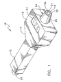
- FIG. 1 depicts one embodiment of a probe 10 that includes a housing 11 forming a handle 12 and a probe head 13.
- the handle 12 and probe head 13 are in different planes to facilitate operator use in making measurements on human skin or other substrates, such as bandages and tapes.
- substrate is intended to cover both skin and such other substrates.
- the probe head 13 carries a sensor head 14 that has a number of sensing elements including a centrally disposed temperature sensor 15 and first and second spaced electrodes.
- the temperature sensor 15 that could be based upon thermistor or thermocouple sensors, could include an electrically isolated conductive housing or can 15A that can act as an inner electrode independently of the operation of the temperature sensor 15.
- This electrode 15A and a spaced outer, concentric electrode 16 act as impedance moisture electrodes.
- a sensor housing 20 contains these elements as well as an insulator 21 disposed between the temperature sensor, acting as the inner electrode 15A, and outer electrode 16 and another insulator 22 disposed about the outer electrode 16.
- the electrodes 15A and 16 are insulated from each other and from the temperature sensor 15.
- a connection 23 at the end of the handle 12 constitutes an interface for attaching the probe 10 to a data processing system thereby to enable data to be processed remotely from the sensor 10 and to allow a single data processing system to accept different probes. If the probe 10 contains an LCD or other display 24 or other electronically driven readout, the signals for such a display 24 could be generated internally of the probe 10 or coupled to the probe 10 through the connection 23.
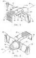
- FIGS. 2 and 3 depict one embodiment of the sensor 14 and related support structures in greater detail.
- the sensor 14 mounts to a sensor support or beam 25 in the form of a planar sheet carried in end supports 26 that are shown schematically.
- the stiffness of the support 25 is selected so that over normal force ranges the support 25 deflects increasingly as force applied to the support increases as the sensor 14 is brought into contact with the skin or other substrate.
- a stop can be incorporated to limit the total deflection of the support 25 and the sensor 14.
- deflecting the sensor 14 along an axis 27 enables piezoelectric transducers 30 and 31 mounted to the support 25 to produce a signal that is a function of the displacement of the board and hence the force applied to the board.
- Two such transducers provide a bipolar output signal in this specific embodiment.
- bus structure 32 that includes a connector section 33 for mating with a female connector mounted on a circuit board not shown.
- Other conductors on the connecting bus 32 will connect to the thermocouple 15 and to the electrode pair formed by the thermocouple can 15A and the concentric outer electrode 16, as shown more clearly in FIG. 2.
- the bus 32 transfers signals representing instantaneous electrical characteristics, temperature and force values to circuitry attached through the connector section 33.
- FIG. 4 depicts the probe 10 and an associated data processing system or system control 33 that provide a measurement of relative hydration in response to the signals from the electrodes 15A and 16, the thermocouple 15 and force transducers 30 and 31.
- the probe operates under the command of the system control 33.
- the system control 33 can comprise any conventional CPU with an input/output interface such as an RS232 interface.
- a probe control 34 that attaches to the connector 24 receives the signals and responds accordingly to each command. More specifically, the probe control 34 comprises a conventional micro-processor or other central processing system that includes a central processor (CP) 35, an I/O unit 36, a memory 37 and a second memory 40 typically implemented as in EPROM or other form of programmable read only memory.
- the probe control 34 produces the appropriate signals for indicating the instantaneous force, temperature and substrate characteristics in response to specific commands from the system control 33.
- the memory 37 includes modules or programs 41 for responding to such commands and, for purposes described later, a constants buffer 42.
- the EPROM 40 includes four registers for storing particular constants. These includes a ⁇ T min register 43, a ⁇ T max register 44, ⁇ F min register 45 and ⁇ F max register 46.
- the temperature sensor 15 connects to a variable gain amplifier circuit 15 to produce an output signal in a predetermined voltage range that is applied to one input of a gated analog to digital converter (ADC) 51.
- ADC analog to digital converter
- a variable gain amplifier 52 receives signals from the force transducers 30 and 31 for application to another input of the gated ADC 51.
- This probe uses an RC generator 53 that responds to an initiation signal from the probe control 34 to generate a signal having an RC time constant that is applied as another input to the gated ADC 51.
- a voltage pulse is applied to an RC circuit with the electrodes being in parallel with the RC circuit.
- the pulse has a fixed value and a duration exceeding a predetermined time.
- the initiation signal enables the RC generator to apply a reference signal to the gated ADC 51 and then to apply the capacitor voltage to the gated ADC.
- the gated ADC 51 operates at a high sampling frequency and is able to obtain voltage measurements over the rise time of the voltage of the capacitor. The result is a measurement of the complex impedance with a quantification of the capacitive reactance that is an indicator of substrate moisture.
- the probe 10 can be connected to the system control 33. Consequently it is important that the signals transferred to the system control 33 from different probes 10 reflect the same temperature and force readings.
- the probe control 34 with its registers 43 through 46, assures accurate and consistent readings from different probes by storing calibration information in the probe 10.
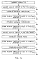
- FIG. 5 depicts a procedure for calibrating the sensor 10 to achieve this consistency. This procedure occurs during the manufacturing process when the probe 10 is placed in an oven and the gain of the variable gain circuit 50 is adjusted over the operating ranges to provide a predetermined range of analog output signals or voltages from the variable gain amplifier 50 in step 60. When this iterative process has been completed, the oven will be held at the minimum temperature. Then the reading from the gated ADC 51 will be stored in a ⁇ T min register 43 in step 62. After the temperature is raised to the maximum operating temperature, step 63 stores the reading from the gated ADC 51 in the ⁇ T max register 44 in step 64.
- a similar process is applied to the force transducers 30 and 31.
- a gain adjustment occurs in step 65.
- a minimum force is applied to the sensor in step 66 and the corresponding reading from the gated ADC 51 is stored in the ⁇ F min register 45 in step 66.
- the value obtained from the gated ADC 51 at a maximum force obtained in step 67 is then stored in the ⁇ F max register 46 in step 68.
- the range of the temperature and force preferably corresponds to a subset of the possible values from the gated ADC 51.
- the gain and offsets might be selected so a minimum operating temperature produces a count of 5 and a maximum operating temperature a count of 246 on an eight-byte gated ADC output.
- a program in the memory 37 can, upon initialization cause the CP to calculate and store concordances between the measured counts and actual force and temperature or corresponding constants in a buffer such as the constants buffer 42.
- output signals representing the force and temperature values of the system control 33 are accurate and repeatable from one probe to another.
- the senor 10 connects to the system control 33 that includes a central processor 70, an I/O unit 71, an input keyboard or keypad 72 and a display 73.
- a memory 74 will contain, among other items, a measurement module or program 75 and various drivers 76.
- the measurement module 75 generates the commands for reading the force, i.e, a READ FORCE command, for reading temperature, i.e., a READ TEMPERATURE command, and for obtaining information from the RC generator 53, i.e, a READ CURVE command.
- These commands are communicated over a bus, such as a serial RS-232 bus 77 and the connector 24 to be received in the probe control 34.
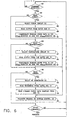
- the central processor 35 operates under a control program to poll the I/O unit 36 to determine whether a command is received. This is shown in FIG. 6 at step 80. If a READ FORCE command is received, step 81 diverts control to step 82 that causes the I/O unit 36 to select and apply the signals from the amplifier 52 to the gated ADC 51 thereby to produce a number that the probe control reads at step 83.
- the control 34 uses the ⁇ F min and ⁇ F max numbers, or information derived from those numbers and stored in the capacity buffer 42 or elsewhere during an initialization process, to provide a normalized force reading in step 84. Thereafter the corresponding data will transfer to the system control in step 85 and control of the central processor 35 then returns to await another command.
- control passes through steps 80 and 81 to step 86 that then diverts control to step 87 whereupon the probe control 34 selects the temperature probe 15 as the input for the gated ADC 51.
- the probe control 34 then reads the output from the gated ADC 51 in step 90 and compensates that reading in step 91 in a fashion analogous to that in which the compensation of step 84 occurs.
- the system again transfers control to step 85 so that the compensated output corresponding to the temperature transfers to the system control 33.
- Step 95 transfers a reference to the gated ADC 51 and that number is received and buffered by the probe control 34. This process also initiates the charging of a capacitor in the RC generator 53. The charging rate, in part, will depend. upon the shunt impedance produced by the substrate across the electrodes 15A and 16. Step 95 takes a number of rapid samples of this charging voltage and the probe control buffers this information. When the process is complete step 95 transfers to step 85 wherein the reference and successive curve data samples are transferred back to the system control 33.
- the measurement module 75 in FIG. 4 can obtain various readings from the probe 10 by issuing a sequence of commands such as the READ FORCE, READ TEMPERATURE and READ CURVE commands.
- An evaluation module 96 can then utilize the information for a number of functions and display information on the visual display 73, a printer or like device connected to the I/O unit 71 or LCD display 23 in the probe 10 shown in FIG. 1 the various readings that occur. With appropriate timing these can become data sets for purposes of evaluation.
- the RC generator 53 and electrodes 15A and 16 coact to provide a measurement of relative substrate moisture.
- the amplifier 50 and thermocouple 15 provide a temperature at the sampling time, and an amplifier 52 and electrodes 30 and 31 provide an indication of the force with which the probe was applied to the skin during the measurement. This data can then be displayed for evaluation and further analysis for determining relative substrate hydration.
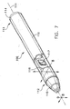
- FIG. 7 depicts a preferred embodiment of this invention that takes the form of a probe 100 that is a variation of the probe 10 in FIG. 1.
- the probe 100 contains a cylindrical housing 110 lying along an axis 111 between a first, distal end 112 and a second, proximal end 113.
- distal is meant to refer to the end that is most the proximate the patient.
- a connector 114 closes the proximal end 113 of the probe housing 110.
- the distal end 112 of the probe housing 110 carries a sensor body 115.
- the probe housing 110 also carries a printed circuit board 116 with a number of components represented by an integrated circuit 117. The components on the printed circuit board perform various functions.
- the probe control 34 in FIG. 4. In other embodiments they may incorporate the functions of the system control 33 shown in FIG. 4. In certain applications, it may be desirable to include all the functions on the printed circuit board 116 and to operate the probe as a self-contained, battery operated measurement system. The end connector 114 could then be used as a convenient means for downloading data to a conventional computer system for storage and analysis.
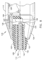
- FIGS. 8 and 9 depict the detail of one sensor body 115 at the distal end 112 of the probe housing 110.
- the sensor body 115 includes a central conductor 120 that lies along an axis 111.
- An inner coaxial insulator 121 lies intermediate the central conductor 120 and an outer coaxial conductor 122 surrounds the inner insulator 121.
- the central conductor 120 is cylindrical, and the coaxial conductor 122 has an annular form.
- An outer insulating body 123 is coaxial with this structure.
- the conductors 120 and 122 and the insulators 121 and 123 constitute a sub-assembly that fits within a housing 124 that, in turn, fits into the distal end 112 of the probe housing 110.
- the housing 124 surrounds a standoff 125 that carries a rigid support 126 for a displacement type.force sensor 127.
- the support 126 is transverse to the axis 111.
- the transducer 127 includes a plunger 130 that contacts a proximal end 131 of the center conductor 120 and that transfers any force to internal measuring components within the transducer 127 that deflect under load.
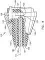
- this sub-assembly is shifted fully to the left until a flange 133 formed on a portion of the outer insulator 123 engages a projection 134 on the standoff 125 that defines a distal-most position of the subassembly, as shown in FIG. 9.
- the position of the support 126 in the standoff 125 is adjusted until the plunger 130 just engages the end 131 of the central conductor 120.
- the support 126 is fixed to the standoff 125, as by soldering or the like.
- the distal end 135 of the sensor body 115 contacts the substrate.
- the sub-assembly including conductors 120 and 122 and insulators 121 and 123 tends to shift proximally thereby to increase the force on the plunger 130 whereupon the transducer 127 generates a force signal that varies with the applied force.
- the internal components of the transducer relax and return the sub-assembly to its original position.
- FIG. 8 does not depict the connections of electrodes 120 and 122 to, or any conductive paths for conveying force signals to, circuitry on the printed circuit board 116. Such connections are well within the capabilities of persons of ordinary skill in the art.
- FIGS. 8 and 9 could also be constructed to accommodate a temperature sensor in the same fashion as is described with FIGS. 1 and 2.
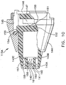
- FIG. 10 depicts an alternative structure that minimizes temperature errors.
- a sensor body 115A has the same general configuration as the sensor body 115 in FIGS. 8 and 9.
- the central conductor 140 and the annular conductor 142 are constituted by a conductive pad and ring, respectively, that lie only at the distal end of an annular insulator 141. All these lie inside an outer insulator that comprises two axially positioned, contiguous sections 143A and 143B.
- the distal section 143A includes inwardly extending, angularly spaced radial spokes or arms 143C that support the inner insulator 141.
- the sensor body 115A in FIG. 9 also includes a standoff 145 that carries a transverse support 146 for a displacement type force transducer 147 with a plunger 150.
- the annular insulator portion 143B provides as surface 151 for contacting the plunger 150 by means of a closed end 152.
- the closed end 152 also forms radially extending, angularly spaced shoulders, such a shoulder 153, that are partially coextensive with the circumference of the outer insulator portion 143B, like the shoulder 133 in FIG. 9.
- the sub-assembly including the conductors 140 and 142 and the insulators 141, 143A and 143B, tend to shift proximally thereby to transfer the force through the plunger 150 to the transducer 147 to produce a force signal.
- FIG. 10 depicts conductors 156 and 157 attached to the central and annular conductors 140 and 142 respectively and a conductor 160 attached to a thermistor 161.
- the conductors 156, 157 and 160 are merely shown as being representative of connections that would made of any various means available to those of ordinary skill in the art to provide the corresponding signals to circuitry on the printed circuit board 115 shown in FIGS. 7 and 8.
- the central conductor 140 and the outer conductor 142 continue to function as electrodes for obtaining substrate impedance measurements.
- the reduced axial length of each minimizes any heat sink effect. Consequently the thermistor 161 can provide more accurate temperature readings related to the substrate temperature at the site being monitored.
- a measurement system for relative substrate hydration that can produce indications of the moisture content of the substrate for a number of different applications.
- Each is,characterized by having an elongated probe housing with a sensor body mounted at a distal end that has first and second electrodes for contacting the substrate at a site for which a relative hydration measurement is desired.
- Each acts as an input to an electrical impedance measurement circuit.
- Each includes a force sensor in the probe housing for generating a signal representing the force exerted by the sensor body on the substrate, as an example of an environmental factor.
- a signal processor can use polling or other techniques to obtain these signals.
- FIGS. 3 and 4 further depict specific circuitry that can be contained either completely or partially within the probe housing to obtain various values.
Landscapes
- Health & Medical Sciences (AREA)
- Life Sciences & Earth Sciences (AREA)
- Molecular Biology (AREA)
- General Health & Medical Sciences (AREA)
- Biophysics (AREA)
- Pathology (AREA)
- Engineering & Computer Science (AREA)
- Biomedical Technology (AREA)
- Heart & Thoracic Surgery (AREA)
- Medical Informatics (AREA)
- Dermatology (AREA)
- Surgery (AREA)
- Animal Behavior & Ethology (AREA)
- Physics & Mathematics (AREA)
- Public Health (AREA)
- Veterinary Medicine (AREA)
- Nuclear Medicine, Radiotherapy & Molecular Imaging (AREA)
- Radiology & Medical Imaging (AREA)
- Measuring And Recording Apparatus For Diagnosis (AREA)
- Organic Low-Molecular-Weight Compounds And Preparation Thereof (AREA)
- Measuring Or Testing Involving Enzymes Or Micro-Organisms (AREA)
- Investigating Or Analyzing Materials By The Use Of Electric Means (AREA)
- Investigating Or Analyzing Materials Using Thermal Means (AREA)
Abstract
Description
- This invention generally relates to devices and methods for measuring relative hydration of a substrate, such as hydration of the human skin or physical substrate materials.
- There is a growing interest in measuring the relative hydration of a substrate. For example, such measurements on human skin provides information about wound healing. Measurements on hydration through films, such as bandages and tapes, can indicate the efficacy of certain compositions of such bandages or tapes in connection with the healing process.
- A number of devices exist for measuring relative hydration of human skin by measuring the water content of the skin typically by measuring skin impedance. For example, United States Letters Patent No. 5,961,471 issued October 5, 1999 by Steven W. Nickson for a probe for a biophysical skin measurement device discloses one such device for measuring relative skin hydration that has received wide acceptance.
- It has been recognized that variations in the force at which such a probe is applied to the skin can affect the measured impedance. For example, United States Letters Patent No. 5,001,436 (1991) to Scott et al. discloses a skin impedance measuring device that recognizes a necessity for some method of controlling the pressure applied. Scott et al. monitor the force applied by the probe and trigger the measurement when an acceptable force exists. United States Letters Patent No. 5,588,440 (1996) to Cowle discloses a system for measuring skin temperature and measuring force. However, the force measurement merely provides an indication of the force as a guide for helping the user control the force at which measurements are taken. In both disclosures it becomes incumbent on the operator to control the force manually in order to obtain sustained measurements.
- Notwithstanding these attempts to compensate for temperature and force in skin moisture measurement devices, there is still a requirement for a relative hydration measuring system that will automatically compensate for the effects of force and temperature variations during the measurement process.
- Therefore it is an object of this invention to provide a relative hydration measuring device and method that can compensate for the force applied by a measurement probe.
- Another object of this invention is to provide a relative hydration measuring device and method that can compensate for the temperature of the substrate being tested.
- Yet another object of this invention is to provide a relative hydration measuring system for human skin that automatically produces a moisture indication that can be compensated for probe force and skin temperature during the measurement. The invention is as defined in the appended set of claims.
- In accordance this invention, relative substrate hydration is obtained by measuring the electrical characteristics of the substrate between electrodes contacting the substrate and by measuring concurrently an environmental factor. These measurements provide the basis for obtaining a value of substrate impedance between the electrodes that indicates relative hydration.
- In accordance with another aspect of this invention, a system for measuring the relative hydration of a substrate comprises a probe having first and second electrodes for contacting the substrate. An electrical impedance measurement circuit periodically generates a value representing the impedance of the substrate between the first and second electrodes. An environmental factor measurement circuit periodically generates a value representing an environmental factor associated with the impedance measurement. A calculator may respond to the impedance and environmental factors signals to produce an indication of relative hydration.
- In accordance with yet another aspect of this invention, a system for measuring the relative hydration of a substrate includes a measurement probe and a data processing system. The measurement probe comprises an elongated probe housing and a sensor body mounted at one end of the probe housing with first and second concentric electrodes for contacting the substrate at a site for which a relative hydration measurement is desired. An electrical impedance measurement circuit in the probe housing generates an impedance signal including information about the capacitive reactance between the first and second electrodes. A force sensor in the probe housing generates a signal representing the force exerted by one of the electrodes on the substrate. A signal processor in the probe housing polls the electrical impedance measurement circuit and the force sensor thereby to generate processed impedance and force measurement signals. A connector at the other end of the probe housing enables communications between the data processing system and the signal processor.
- In accordance with still another aspect of this invention, a system for measuring relative hydration of a substrate includes a measurement probe and a data processing system. The measurement probe comprises an elongated probe housing and a sensor body mounted at one end of the probe housing with first and second concentric electrodes for contacting the substrate at a site for which a measurement of relative hydration is desired. An electrical impedance measurement circuit in the probe housing generates an impedance signal representing the impedance of the substrate between the first and second electrodes. A temperature sensor in the probe housing generates a signal representing the temperature of the skin contacting the electrodes. A signal processor in the probe housing polls the impedance measurement circuit and the temperature sensor thereby to generate processed impedance and temperature measurement signals. A connector at the other end of the probe housing enables communications between the data processing system and the signal processor.
- The appended claims particularly point out and distinctly claim the subject matter of this invention. The various objects, advantages and novel features of this invention will be more fully apparent from a reading of the following detailed description in conjunction with the accompanying drawings in which like reference numerals refer to like parts, and in which:
- FIG. 1 depicts a measurement sensor constructed in accordance with this invention;
- FIG. 2 is a view of a portion of the sensor shown in FIG. 1;
- FIG. 3 is an alternate view of the structure shown in FIG. 2;
- FIG. 4 is a schematic of circuitry for obtaining the normalized impedance measurements;
- FIG. 5 is a flow diagram representing the steps for calibrating the sensor in FIG. 1;
- FIG. 6 is a flow diagram illustrating the steps for taking an impedance measurement;
- FIG. 7 is a view of an alternate, preferred embodiment of a sensor constructed in accordance with this invention;
- FIGS. 8 and 9 are views, partially in section, of a portion of the sensor taken along lines 8-8 and 9-9 in FIG. 7; and
- FIG. 10 is a view, partially in section, of an alternate structure for the sensor shown in FIGS. 8 and 9.
- FIG. 1 depicts one embodiment of a
probe 10 that includes ahousing 11 forming ahandle 12 and aprobe head 13. In this particular embodiment thehandle 12 andprobe head 13 are in different planes to facilitate operator use in making measurements on human skin or other substrates, such as bandages and tapes. In the following discussion, "substrate" is intended to cover both skin and such other substrates. - The
probe head 13 carries asensor head 14 that has a number of sensing elements including a centrally disposedtemperature sensor 15 and first and second spaced electrodes. Thetemperature sensor 15 that could be based upon thermistor or thermocouple sensors, could include an electrically isolated conductive housing or can 15A that can act as an inner electrode independently of the operation of thetemperature sensor 15. Thiselectrode 15A and a spaced outer,concentric electrode 16 act as impedance moisture electrodes. Asensor housing 20 contains these elements as well as aninsulator 21 disposed between the temperature sensor, acting as theinner electrode 15A, andouter electrode 16 and anotherinsulator 22 disposed about theouter electrode 16. Thus theelectrodes temperature sensor 15. Aconnection 23 at the end of thehandle 12 constitutes an interface for attaching theprobe 10 to a data processing system thereby to enable data to be processed remotely from thesensor 10 and to allow a single data processing system to accept different probes. If theprobe 10 contains an LCD orother display 24 or other electronically driven readout, the signals for such adisplay 24 could be generated internally of theprobe 10 or coupled to theprobe 10 through theconnection 23. - FIGS. 2 and 3 depict one embodiment of the
sensor 14 and related support structures in greater detail. Thesensor 14 mounts to a sensor support orbeam 25 in the form of a planar sheet carried inend supports 26 that are shown schematically. The stiffness of thesupport 25 is selected so that over normal force ranges thesupport 25 deflects increasingly as force applied to the support increases as thesensor 14 is brought into contact with the skin or other substrate. Although not shown in the drawings, a stop can be incorporated to limit the total deflection of thesupport 25 and thesensor 14. - As shown more clearly in FIG. 2, deflecting the
sensor 14 along anaxis 27 enablespiezoelectric transducers support 25 to produce a signal that is a function of the displacement of the board and hence the force applied to the board. Two such transducers provide a bipolar output signal in this specific embodiment. - Leads from these
transducers bus structure 32 that includes aconnector section 33 for mating with a female connector mounted on a circuit board not shown. Other conductors on the connectingbus 32 will connect to thethermocouple 15 and to the electrode pair formed by the thermocouple can 15A and the concentricouter electrode 16, as shown more clearly in FIG. 2. Thus thebus 32 transfers signals representing instantaneous electrical characteristics, temperature and force values to circuitry attached through theconnector section 33. - FIG. 4 depicts the
probe 10 and an associated data processing system orsystem control 33 that provide a measurement of relative hydration in response to the signals from theelectrodes thermocouple 15 andforce transducers system control 33. In a preferred embodiment thesystem control 33 can comprise any conventional CPU with an input/output interface such as an RS232 interface. - A
probe control 34 that attaches to theconnector 24 receives the signals and responds accordingly to each command. More specifically, theprobe control 34 comprises a conventional micro-processor or other central processing system that includes a central processor (CP) 35, an I/O unit 36, amemory 37 and asecond memory 40 typically implemented as in EPROM or other form of programmable read only memory. Theprobe control 34 produces the appropriate signals for indicating the instantaneous force, temperature and substrate characteristics in response to specific commands from thesystem control 33. Thememory 37 includes modules orprograms 41 for responding to such commands and, for purposes described later, aconstants buffer 42. Of particular interest for this invention, theEPROM 40 includes four registers for storing particular constants. These includes a ΔTmin register 43, a ΔTmax register 44, ΔFmin register 45 and ΔFmax register 46. - Still referring to FIG. 4, the
temperature sensor 15 connects to a variablegain amplifier circuit 15 to produce an output signal in a predetermined voltage range that is applied to one input of a gated analog to digital converter (ADC) 51. Similarly, avariable gain amplifier 52 receives signals from theforce transducers gated ADC 51. - Any number of circuits exist for providing a signal that indicates the moisture content. This probe uses an
RC generator 53 that responds to an initiation signal from theprobe control 34 to generate a signal having an RC time constant that is applied as another input to thegated ADC 51. In the system depicted in FIG. 4, a voltage pulse is applied to an RC circuit with the electrodes being in parallel with the RC circuit. The pulse has a fixed value and a duration exceeding a predetermined time. The initiation signal enables the RC generator to apply a reference signal to thegated ADC 51 and then to apply the capacitor voltage to the gated ADC. Thegated ADC 51 operates at a high sampling frequency and is able to obtain voltage measurements over the rise time of the voltage of the capacitor. The result is a measurement of the complex impedance with a quantification of the capacitive reactance that is an indicator of substrate moisture. - As previously indicated, the
probe 10 can be connected to thesystem control 33. Consequently it is important that the signals transferred to thesystem control 33 fromdifferent probes 10 reflect the same temperature and force readings. Theprobe control 34 with itsregisters 43 through 46, assures accurate and consistent readings from different probes by storing calibration information in theprobe 10. - FIG. 5 depicts a procedure for calibrating the
sensor 10 to achieve this consistency. This procedure occurs during the manufacturing process when theprobe 10 is placed in an oven and the gain of thevariable gain circuit 50 is adjusted over the operating ranges to provide a predetermined range of analog output signals or voltages from thevariable gain amplifier 50 instep 60. When this iterative process has been completed, the oven will be held at the minimum temperature. Then the reading from thegated ADC 51 will be stored in a ΔTmin register 43 instep 62. After the temperature is raised to the maximum operating temperature, step 63 stores the reading from thegated ADC 51 in the ΔTmax register 44 instep 64. - A similar process is applied to the
force transducers step 65. Then a minimum force is applied to the sensor instep 66 and the corresponding reading from thegated ADC 51 is stored in the ΔFmin register 45 instep 66. The value obtained from thegated ADC 51 at a maximum force obtained instep 67 is then stored in the ΔFmax register 46 instep 68. - In both cases, the range of the temperature and force preferably corresponds to a subset of the possible values from the
gated ADC 51. For example, the gain and offsets might be selected so a minimum operating temperature produces a count of 5 and a maximum operating temperature a count of 246 on an eight-byte gated ADC output. As will now be apparent, a program in thememory 37 can, upon initialization cause the CP to calculate and store concordances between the measured counts and actual force and temperature or corresponding constants in a buffer such as theconstants buffer 42. Thus output signals representing the force and temperature values of thesystem control 33 are accurate and repeatable from one probe to another. - During normal operation, the
sensor 10 connects to thesystem control 33 that includes acentral processor 70, an I/O unit 71, an input keyboard orkeypad 72 and adisplay 73. Amemory 74 will contain, among other items, a measurement module orprogram 75 and various drivers 76. Themeasurement module 75 generates the commands for reading the force, i.e, a READ FORCE command, for reading temperature, i.e., a READ TEMPERATURE command, and for obtaining information from theRC generator 53, i.e, a READ CURVE command. These commands are communicated over a bus, such as a serial RS-232bus 77 and theconnector 24 to be received in theprobe control 34. - In one particular embodiment, the
central processor 35 operates under a control program to poll the I/O unit 36 to determine whether a command is received. This is shown in FIG. 6 atstep 80. If a READ FORCE command is received,step 81 diverts control to step 82 that causes the I/O unit 36 to select and apply the signals from theamplifier 52 to thegated ADC 51 thereby to produce a number that the probe control reads atstep 83. Thecontrol 34 then uses the ΔFmin and ΔFmax numbers, or information derived from those numbers and stored in thecapacity buffer 42 or elsewhere during an initialization process, to provide a normalized force reading instep 84. Thereafter the corresponding data will transfer to the system control instep 85 and control of thecentral processor 35 then returns to await another command. - When a READ TEMPERATURE command is received, control passes through
steps probe control 34 selects thetemperature probe 15 as the input for thegated ADC 51. Theprobe control 34 then reads the output from thegated ADC 51 instep 90 and compensates that reading instep 91 in a fashion analogous to that in which the compensation ofstep 84 occurs. The system again transfers control to step 85 so that the compensated output corresponding to the temperature transfers to thesystem control 33. - When a READ CURVE command is received by the
probe control 34, thecentral processor 35 usessteps Step 93 selects theRC generator 53.Step 94 transfers a reference to thegated ADC 51 and that number is received and buffered by theprobe control 34. This process also initiates the charging of a capacitor in theRC generator 53. The charging rate, in part, will depend. upon the shunt impedance produced by the substrate across theelectrodes Step 95 takes a number of rapid samples of this charging voltage and the probe control buffers this information. When the process iscomplete step 95 transfers to step 85 wherein the reference and successive curve data samples are transferred back to thesystem control 33. - Thus it will be apparent that the
measurement module 75 in FIG. 4 can obtain various readings from theprobe 10 by issuing a sequence of commands such as the READ FORCE, READ TEMPERATURE and READ CURVE commands. Anevaluation module 96 can then utilize the information for a number of functions and display information on thevisual display 73, a printer or like device connected to the I/O unit 71 orLCD display 23 in theprobe 10 shown in FIG. 1 the various readings that occur. With appropriate timing these can become data sets for purposes of evaluation. - Therefore there has been disclosed a
probe 10 and asystem control 33 that cooperate to obtain data concerning substrate hydration. TheRC generator 53 andelectrodes amplifier 50 andthermocouple 15 provide a temperature at the sampling time, and anamplifier 52 andelectrodes - FIG. 7 depicts a preferred embodiment of this invention that takes the form of a
probe 100 that is a variation of theprobe 10 in FIG. 1. Theprobe 100 contains acylindrical housing 110 lying along anaxis 111 between a first,distal end 112 and a second,proximal end 113. In the case of theprobe 100 "distal" is meant to refer to the end that is most the proximate the patient. Aconnector 114 closes theproximal end 113 of theprobe housing 110. Thedistal end 112 of theprobe housing 110 carries asensor body 115. In this particular embodiment theprobe housing 110 also carries a printedcircuit board 116 with a number of components represented by anintegrated circuit 117. The components on the printed circuit board perform various functions. At a minimum they include the functions of theprobe control 34 in FIG. 4. In other embodiments they may incorporate the functions of thesystem control 33 shown in FIG. 4. In certain applications, it may be desirable to include all the functions on the printedcircuit board 116 and to operate the probe as a self-contained, battery operated measurement system. Theend connector 114 could then be used as a convenient means for downloading data to a conventional computer system for storage and analysis. - FIGS. 8 and 9 depict the detail of one
sensor body 115 at thedistal end 112 of theprobe housing 110. Thesensor body 115 includes acentral conductor 120 that lies along anaxis 111. An innercoaxial insulator 121 lies intermediate thecentral conductor 120 and an outercoaxial conductor 122 surrounds theinner insulator 121. In this specific embodiment, thecentral conductor 120 is cylindrical, and thecoaxial conductor 122 has an annular form. An outer insulatingbody 123 is coaxial with this structure. In accordance with this invention theconductors insulators housing 124 that, in turn, fits into thedistal end 112 of theprobe housing 110. - The
housing 124 surrounds astandoff 125 that carries arigid support 126 for a displacementtype.force sensor 127. Thesupport 126 is transverse to theaxis 111. Thetransducer 127 includes aplunger 130 that contacts aproximal end 131 of thecenter conductor 120 and that transfers any force to internal measuring components within thetransducer 127 that deflect under load. When thesensor body 115 is assembled, the sub-assembly comprising theconductors insulators housing 124 such that the sub-assembly can be displaced incrementally along theaxis 111. During manufacture, this sub-assembly is shifted fully to the left until aflange 133 formed on a portion of theouter insulator 123 engages aprojection 134 on thestandoff 125 that defines a distal-most position of the subassembly, as shown in FIG. 9. Next the position of thesupport 126 in thestandoff 125 is adjusted until theplunger 130 just engages theend 131 of thecentral conductor 120. Then thesupport 126 is fixed to thestandoff 125, as by soldering or the like. - In use, when the
probe 100 in FIG. 7 is applied to a substrate, thedistal end 135 of thesensor body 115 contacts the substrate. As force is applied by urging theprobe housing 110 distally, to the left in FIG. 7, thesub-assembly including conductors insulators plunger 130 whereupon thetransducer 127 generates a force signal that varies with the applied force. When theprobe 100 is removed from the substrate, the internal components of the transducer, as known, relax and return the sub-assembly to its original position. - FIG. 8 does not depict the connections of
electrodes circuit board 116. Such connections are well within the capabilities of persons of ordinary skill in the art. - Any number of different mechanical configurations could be devised to provide this force measuring function. The structure in FIGS. 8 and 9 could also be constructed to accommodate a temperature sensor in the same fashion as is described with FIGS. 1 and 2.
- If the
conductors sensor body 115A has the same general configuration as thesensor body 115 in FIGS. 8 and 9. However, thecentral conductor 140 and theannular conductor 142 are constituted by a conductive pad and ring, respectively, that lie only at the distal end of anannular insulator 141. All these lie inside an outer insulator that comprises two axially positioned,contiguous sections distal section 143A includes inwardly extending, angularly spaced radial spokes orarms 143C that support theinner insulator 141. - The
sensor body 115A in FIG. 9 also includes astandoff 145 that carries atransverse support 146 for a displacementtype force transducer 147 with aplunger 150. In this particular example, however, theannular insulator portion 143B provides assurface 151 for contacting theplunger 150 by means of aclosed end 152. Theclosed end 152 also forms radially extending, angularly spaced shoulders, such ashoulder 153, that are partially coextensive with the circumference of theouter insulator portion 143B, like theshoulder 133 in FIG. 9. Thus, as a force is applied to anend 155 of the sensor sub-assembly, the sub-assembly including theconductors insulators plunger 150 to thetransducer 147 to produce a force signal. - FIG. 10 depicts
conductors annular conductors conductor 160 attached to athermistor 161. Theconductors circuit board 115 shown in FIGS. 7 and 8. - With this structure the
central conductor 140 and theouter conductor 142 continue to function as electrodes for obtaining substrate impedance measurements. However, the reduced axial length of each minimizes any heat sink effect. Consequently thethermistor 161 can provide more accurate temperature readings related to the substrate temperature at the site being monitored. - Thus in accordance with this invention there have been disclosed different embodiments of a measurement system for relative substrate hydration that can produce indications of the moisture content of the substrate for a number of different applications. Each is,characterized by having an elongated probe housing with a sensor body mounted at a distal end that has first and second electrodes for contacting the substrate at a site for which a relative hydration measurement is desired. Each acts as an input to an electrical impedance measurement circuit. Each includes a force sensor in the probe housing for generating a signal representing the force exerted by the sensor body on the substrate, as an example of an environmental factor. In each a signal processor can use polling or other techniques to obtain these signals. FIGS. 3 and 4 further depict specific circuitry that can be contained either completely or partially within the probe housing to obtain various values.
- It will be apparent, that a number of variations can be made to the specifically disclosed embodiment without departing from the scope of this invention. For example, specific detailed sensor body structures have been shown. Other structures could be substituted using different force transducers and temperature sensors. The circuitry on a printed circuit board, such as the printed
circuit board 116 shown in FIG. 7, can contain some or all of the electronics shown in FIGS. 3 and 4 or even contain all the circuitry necessary for identifying patients and storing information for subsequent downloading to an external data processing system. - Therefore, it is the intent of the appended claims to cover all such variations and modifications as come within the scope of this invention as defined in the claims.
Claims (24)
- A method for measuring relative hydration of a substrate comprising the steps of:A) measuring electrical characteristics of the substrate between electrodes contacting the substrate,B) measuring an environmental factor of the substrate concurrently with said measurement of electrical characteristics, andC) utilizing the measurements for said electrical characteristics and environmental factor measurements for obtaining a substrate impedance value that represents relative hydration of the substrate.
- A method as recited in claim 1 wherein said environmental factor is substrate temperature and said environmental factor measuring includes measuring the temperature of the substrate at the site of said electrical characteristic measurement.
- A method as recited in claim 1 wherein said substrate electrical characteristics measurement includes applying an electrical impedance sensor to a site of the substrate and said environmental factor is the force with which the impedance sensor is applied to the- substrate, said environmental factor measuring including measuring the force on the impedance sensor at the site of the electrical impedance sensor measurement.
- A method as recited in claim 3 wherein said environmental factor measuring includes measuring the temperature of the substrate at the site of the electrical impedance characteristics measurement.
- A method as recited in claim 1 wherein said electrical characteristic measuring step includes:i) applying a probe with first and second electrodes to a site of the substrate, andii) iteratively measuring the impedance of the substrate between the electrodes at the site.
- A method as recited in claim 5 wherein said environmental factor is the substrate temperature and said environmental factor measuring includes iteratively measuring the temperature of the substrate at the site of said electrical impedance measurement concurrently with said iterative impedance measurement.
- A method as recited in claim 5 wherein said environmental factor is a force with which the probe is applied to the site and said environmental factor measuring includes iteratively measuring the force of the probe at the site of the electrical impedance measurement..
- A method as recited in claim 7 additionally comprising the step of iteratively measuring substrate temperature at the site of the electrical impedance measurement.
- A system for measuring the relative hydration of a substrate comprising:A) a probe (10) having first and second electrodes (15A, 16) for contacting the substrate at a site for which a measurement is desired,B) an electrical impedance measurement circuit (53,75) for periodically generating a value representing substrate impedance between the first and second electrodes,C) an environmental factor measurement circuit for periodically generating a value representing a substrate environmental factor associated with the impedance measurement, andD) a substrate hydration calculator (96) for combining the impedance and environmental factor signals to generate an output representing the relative hydration of the substrate.
- A system as recited in claim 9 wherein the environmental factor is substrate temperature and said environmental factor measuring circuit includes a temperature sensor (15) in said probe for generating a signal representing substrate temperature at the site.
- A system as recited in claim 9 wherein the environmental factor is a force with which said probe is applied to the substrate and said environmental factor measuring circuit includes a force sensor (30, 31) for measuring force applied to one of said electrodes.
- A system as recited in claim 11 additionally comprising a temperature sensor (15) in said probe for generating a signal representing substrate temperature at the site.
- A system as recited in claim 9 wherein said probe comprises:an elongated probe housing, wherein said electrical impedance measurement circuit includes a sensor body mounted at one end of said probe housing with first andsecond concentric electrodes for contacting the substrate at a site for which a measurement is desired and an electrical impedance measurement circuit in said probe housing for generating an impedance signal representing substrate impedance between the first andsecond electrodes, wherein said environmental factor measurement circuit includes a force sensor in said probe housing for generating a signal representing a force exerted by one of said electrodes on the substrate, and wherein said calculator includes a signal processor in said probe housing for polling said electrical impedance measurement circuit and said force sensor thereby to generate processed impedance andforce measurement signals, said system additionally includes a connector at the other end of said probe housing for enabling communications of the processed impedance and force measurement signals to said data processing system from said signal processor whereby the data processing system combines the processed impedance and force measurement signals to produce a measurement of relative hydration.
- A system as recited in claim 13 wherein said probe housing lies along an axis, said first electrode. comprises a central conductor lying on the axis and said second electrode comprises a conductor coaxial with and spaced from said central conductor, said probe additionally including an insulator between said central and coaxial conductors.
- A system as recited in claim 14 wherein said sensor body extends between a first end that contacts the substrate and a second end proximate said probe housing, said force sensor comprising:i) a support attached at the second end of said sensor body transverse to the axis, andii) a displacement force transducer on said support and contacting said sensor body whereby any force applied to the first end of said sensor body is transmitted through said coaxial conductor to said force transducer.
- A system as recited in claim 15 wherein said probe is adapted to undergo a specified range of forces having first and second ends and wherein said signal processor includes first and second storage registers for the signal values from said force transducer when the force applied to said coaxial conductor is at the first and second ends of the force range, respectively.
- A system as recited in claim 15 additionally comprising a temperature sensor in said sensor body to sense substrate temperature proximate the site at which said electrodes contact the substrate, said signal processor additionally including a circuit for generating a processed temperature signal for transfer to the data processing system.
- A system as recited in claim 17 wherein said probe is adapted to operate under a specified range of substrate temperatures having first and second ends and wherein said signal processor includes third and fourth storage registers for the signal values from said temperature sensor when the temperature applied to said temperature sensor is at the first and second ends of the substrate temperature range, respectively,
- A system as recited in claim 17 wherein said signal processor provides outputs for each of the impedance, force and temperature readings and wherein said data processing system includes means for requesting the transfer of each of the readings.
- A system as recited in claim 17 wherein said signal processor provides outputs for each of the impedance, force and temperature readings and wherein said data processing system includes means for requesting the transfer of each of the readings on an iterative basis.
- A system as recited in claim 9 wherein said probe comprises an elongated probe housing extending between first and second ends, wherein said electrical impedance measurement circuit includes a sensor body mounted at the first end of said probe housing with first and second concentric electrodes for contacting the substrate at a site for which a moisture measurement is desired, and an electrical impedance measurement circuit in said probe housing for generating an impedance signal representing substrate impedance between the first and second electrodes, wherein said environmental factor measurement circuit includes a temperature sensor in said probe housing for generating a signal representing substrate temperature contacting said electrodes, and wherein said calculator includes a signal processor in said probe housing for polling said electrical impedance measurement circuit and said temperature sensor thereby to generate processed impedance and temperature measurement signals, said system additionally including a.connector at the second end of said probe housing for enabling communications between said data processing system and said signal processor whereby the data processing system combines the processed impedance and temperature signals to produce a measurement of relative hydration.
- A system as recited in claim 21 wherein probe housing lies along an axis, said first electrode comprises a central conductor lying on the axis and said second electrode comprises a conductor coaxial with and spaced from said central conductor, said probe additionally including an insulator between said central and coaxial conductors.
- A system as recited in claim 22 wherein said probe is adapted to operate under a specified range of substrate temperatures having first and second ends and wherein said signal processor includes first and second storage registers for the signal values from said temperature sensor when the temperature applied to said temperature sensor is at the first and second ends of the temperature range, respectively.
- A system as recited in claim 23 wherein said signal processor provides outputs for each of the impedance and temperature readings and wherein said data processing system includes means for requesting the transfer of each of the readings.
Applications Claiming Priority (3)
| Application Number | Priority Date | Filing Date | Title |
|---|---|---|---|
| US13008099P | 1999-04-20 | 1999-04-20 | |
| US130080P | 1999-04-20 | ||
| PCT/US2000/010811 WO2000062671A1 (en) | 1999-04-20 | 2000-04-20 | Apparatus for measuring relative hydration of a substrate |
Publications (2)
| Publication Number | Publication Date |
|---|---|
| EP1171030A1 EP1171030A1 (en) | 2002-01-16 |
| EP1171030B1 true EP1171030B1 (en) | 2006-11-02 |
Family
ID=22442963
Family Applications (1)
| Application Number | Title | Priority Date | Filing Date |
|---|---|---|---|
| EP00923568A Expired - Lifetime EP1171030B1 (en) | 1999-04-20 | 2000-04-20 | Method and apparatus for measuring relative hydration of a substrate |
Country Status (8)
| Country | Link |
|---|---|
| US (2) | US6370426B1 (en) |
| EP (1) | EP1171030B1 (en) |
| JP (1) | JP2003521963A (en) |
| AT (1) | ATE343963T1 (en) |
| AU (1) | AU4366900A (en) |
| DE (1) | DE60031661D1 (en) |
| HK (1) | HK1043471A1 (en) |
| WO (1) | WO2000062671A1 (en) |
Cited By (1)
| Publication number | Priority date | Publication date | Assignee | Title |
|---|---|---|---|---|
| EP3210533A1 (en) * | 2016-02-23 | 2017-08-30 | Peter Peutler | Device and method for measuring a cutaneous electric resistance |
Families Citing this family (96)
| Publication number | Priority date | Publication date | Assignee | Title |
|---|---|---|---|---|
| FI111298B (en) * | 1999-11-16 | 2003-06-30 | Delfin Technologies Ltd | A method for measuring skin moisture and a device for applying the method |
| SE518253C2 (en) * | 2001-01-22 | 2002-09-17 | Britta Sethson | Device for clinical impedance measurement of skin where a measuring probe is designed with sensors to sense the local measurement environment |
| US6591122B2 (en) * | 2001-03-16 | 2003-07-08 | Nellcor Puritan Bennett Incorporated | Device and method for monitoring body fluid and electrolyte disorders |
| US7239902B2 (en) * | 2001-03-16 | 2007-07-03 | Nellor Puritan Bennett Incorporated | Device and method for monitoring body fluid and electrolyte disorders |
| US7657292B2 (en) * | 2001-03-16 | 2010-02-02 | Nellcor Puritan Bennett Llc | Method for evaluating extracellular water concentration in tissue |
| US8135448B2 (en) * | 2001-03-16 | 2012-03-13 | Nellcor Puritan Bennett Llc | Systems and methods to assess one or more body fluid metrics |
| FI109651B (en) * | 2001-03-23 | 2002-09-30 | Delfin Technologies Ltd | Procedure for measuring edema in tissues |
| US7044911B2 (en) * | 2001-06-29 | 2006-05-16 | Philometron, Inc. | Gateway platform for biological monitoring and delivery of therapeutic compounds |
| FR2831416B1 (en) * | 2001-10-29 | 2004-06-18 | Licorne Lab | APPARATUS FOR ANALYZING THE PHYSICO-CHEMICAL PROPERTIES OF A SKIN SURFACE |
| US20070255169A1 (en) * | 2001-11-19 | 2007-11-01 | Dune Medical Devices Ltd. | Clean margin assessment tool |
| US7505811B2 (en) | 2001-11-19 | 2009-03-17 | Dune Medical Devices Ltd. | Method and apparatus for examining tissue for predefined target cells, particularly cancerous cells, and a probe useful in such method and apparatus |
| US6813515B2 (en) * | 2002-01-04 | 2004-11-02 | Dune Medical Devices Ltd. | Method and system for examining tissue according to the dielectric properties thereof |
| US8032211B2 (en) * | 2002-01-04 | 2011-10-04 | Dune Medical Devices Ltd. | Probes, systems, and methods for examining tissue according to the dielectric properties thereof |
| US8019411B2 (en) * | 2002-01-04 | 2011-09-13 | Dune Medical Devices Ltd. | Probes, systems, and methods for examining tissue according to the dielectric properties thereof |
| US8116845B2 (en) | 2005-08-04 | 2012-02-14 | Dune Medical Devices Ltd. | Tissue-characterization probe with effective sensor-to-tissue contact |
| US7809425B2 (en) * | 2003-07-24 | 2010-10-05 | Dune Medical Devices Ltd. | Method and apparatus for examining a substance, particularly tissue, to characterize its type |
| US8721565B2 (en) * | 2005-08-04 | 2014-05-13 | Dune Medical Devices Ltd. | Device for forming an effective sensor-to-tissue contact |
| WO2006103665A2 (en) * | 2005-03-29 | 2006-10-05 | Dune Medical Devices Ltd. | Electromagnetic sensors for tissue characterization |
| FR2835732B1 (en) * | 2002-02-11 | 2004-11-12 | Spinevision | DEVICE FOR TRACKING THE PENETRATION OF A PENETRATION MEANS IN ANATOMICAL ELEMENTS |
| JP2004150960A (en) * | 2002-10-30 | 2004-05-27 | Nichirei Corp | Probe for measuring physical property |
| FR2849764B1 (en) | 2003-01-14 | 2012-12-14 | Oreal | DEVICE AND METHOD, IN PARTICULAR FOR EVALUATING THE MOISTURIZATION OF THE SKIN OR MUCOSES |
| US7542796B2 (en) * | 2003-07-16 | 2009-06-02 | Biomeridian International, Inc. | Methods for obtaining quick, repeatable, and non-invasive bioelectrical signals in living organisms |
| EP2382920A1 (en) * | 2003-08-20 | 2011-11-02 | Philometron, Inc. | Hydration monitoring |
| US20050181645A1 (en) * | 2003-09-11 | 2005-08-18 | Super Talent Electronics Inc. | Tube-Shaped Universal-Serial-Bus (USB) Flash-Memory Device with End Clips that Hold an internal Printed-Circuit-Board (PCB) |
| US20050119537A1 (en) * | 2003-10-08 | 2005-06-02 | Campbell Michael J.E. | Method and apparatus for performing concurrent multiple measurements of relative hydration |
| US7087019B2 (en) * | 2004-01-16 | 2006-08-08 | Han-Chin Kao | Apparatus for testing skin moisture |
| US7277741B2 (en) * | 2004-03-09 | 2007-10-02 | Nellcor Puritan Bennett Incorporated | Pulse oximetry motion artifact rejection using near infrared absorption by water |
| EP1740102A4 (en) * | 2004-03-23 | 2012-02-15 | Dune Medical Devices Ltd | Clean margin assessment tool |
| US7904145B2 (en) | 2004-03-23 | 2011-03-08 | Dune Medical Devices Ltd. | Clean margin assessment tool |
| US9750425B2 (en) | 2004-03-23 | 2017-09-05 | Dune Medical Devices Ltd. | Graphical user interfaces (GUI), methods and apparatus for data presentation |
| US7161364B1 (en) | 2004-05-11 | 2007-01-09 | Nova Technology Corporation | Dermal phase meter with replaceable probe tips |
| US7195595B2 (en) * | 2004-05-21 | 2007-03-27 | Nova Technology Corporation | Method and apparatus for monitoring the efficacy of fluid resuscitation |
| WO2006029035A1 (en) * | 2004-09-02 | 2006-03-16 | Philometron, Inc. | Monitoring platform for wound and ulcer monitoring and detection |
| US20060079774A1 (en) * | 2004-10-08 | 2006-04-13 | Wendell Anderson | Microwave biopsy probe |
| US8734341B2 (en) * | 2004-12-20 | 2014-05-27 | Ipventure, Inc. | Method and apparatus to sense hydration level of a person |
| US11013461B2 (en) | 2004-12-20 | 2021-05-25 | Ipventure, Inc. | Method and apparatus for hydration level of a person |
| US8118740B2 (en) * | 2004-12-20 | 2012-02-21 | Ipventure, Inc. | Moisture sensor for skin |
| US10258278B2 (en) | 2004-12-20 | 2019-04-16 | Ipventure, Inc. | Method and apparatus to sense hydration level of a person |
| US8202217B2 (en) * | 2004-12-20 | 2012-06-19 | Ip Venture, Inc. | Healthcare base |
| CN101188968B (en) * | 2005-03-09 | 2010-09-29 | 拉米尔·法里托维奇·穆辛 | Method and device for microcalorimetrically measuring a tissue local metabolism speed, intracellular tissue water content, blood biochemical component concentration and a cardio-vascular system tensio |
| KR100634544B1 (en) * | 2005-06-04 | 2006-10-13 | 삼성전자주식회사 | Apparatus and method for measuring moisture content in skin using portable terminal |
| CN101252880A (en) * | 2005-09-02 | 2008-08-27 | 宝洁公司 | Methods for retail measurement of skin moisture content |
| CN101252879A (en) * | 2005-09-02 | 2008-08-27 | 宝洁公司 | Efficacious scalp health predictor |
| US8255025B2 (en) * | 2006-06-09 | 2012-08-28 | Nellcor Puritan Bennett Llc | Bronchial or tracheal tissular water content sensor and system |
| US7666443B2 (en) * | 2006-07-13 | 2010-02-23 | Conopco, Inc. | Dispersed particle compositions for enhancing post wash hydration comprising amphiphiles and moisturization additives of defined HLB |
| WO2008006697A2 (en) * | 2006-07-13 | 2008-01-17 | Unilever Plc | Dispersed particle compositions for enhancing post wash hydration |
| US8180419B2 (en) * | 2006-09-27 | 2012-05-15 | Nellcor Puritan Bennett Llc | Tissue hydration estimation by spectral absorption bandwidth measurement |
| US7643858B2 (en) * | 2006-09-28 | 2010-01-05 | Nellcor Puritan Bennett Llc | System and method for detection of brain edema using spectrophotometry |
| US8116852B2 (en) * | 2006-09-29 | 2012-02-14 | Nellcor Puritan Bennett Llc | System and method for detection of skin wounds and compartment syndromes |
| DE102006060921A1 (en) * | 2006-12-20 | 2008-06-26 | Endress + Hauser Gmbh + Co. Kg | Device for determining and / or monitoring a process variable |
| FR2911232B1 (en) * | 2007-01-05 | 2009-03-20 | Siemens Vdo Automotive Sas | METHOD FOR OPERATING A SERVICE BY A HOST SYSTEM HAVING A MAN-MACHINE INTERFACE, THE HOST SYSTEM AND A SET OF A MOBILE ELECTRONIC APPARATUS AND HOST SYSTEM |
| KR100857180B1 (en) * | 2007-01-22 | 2008-09-05 | 삼성전자주식회사 | Skin hydration measuring apparatus for minimizing power consumption |
| CN101621968B (en) * | 2007-02-26 | 2013-06-19 | 皇家飞利浦电子股份有限公司 | Pointing device for medical imaging |
| US8147423B2 (en) * | 2007-03-01 | 2012-04-03 | Dune Medical Devices, Ltd. | Tissue-characterization system and method |
| US20080221411A1 (en) * | 2007-03-09 | 2008-09-11 | Nellcor Puritan Bennett Llc | System and method for tissue hydration estimation |
| US20080220512A1 (en) * | 2007-03-09 | 2008-09-11 | Nellcor Puritan Bennett Llc | Tunable laser-based spectroscopy system for non-invasively measuring body water content |
| US8109882B2 (en) * | 2007-03-09 | 2012-02-07 | Nellcor Puritan Bennett Llc | System and method for venous pulsation detection using near infrared wavelengths |
| US8280469B2 (en) | 2007-03-09 | 2012-10-02 | Nellcor Puritan Bennett Llc | Method for detection of aberrant tissue spectra |
| US8690864B2 (en) * | 2007-03-09 | 2014-04-08 | Covidien Lp | System and method for controlling tissue treatment |
| US8357090B2 (en) * | 2007-03-09 | 2013-01-22 | Covidien Lp | Method and apparatus for estimating water reserves |
| US8175665B2 (en) | 2007-03-09 | 2012-05-08 | Nellcor Puritan Bennett Llc | Method and apparatus for spectroscopic tissue analyte measurement |
| US8346327B2 (en) | 2007-03-09 | 2013-01-01 | Covidien Lp | Method for identification of sensor site by local skin spectrum data |
| WO2009131664A2 (en) * | 2008-04-21 | 2009-10-29 | Carl Frederick Edman | Metabolic energy monitoring system |
| US20100069779A1 (en) * | 2008-09-15 | 2010-03-18 | Zvi Nachum | Soft tissue moisture analyzer |
| US8406865B2 (en) * | 2008-09-30 | 2013-03-26 | Covidien Lp | Bioimpedance system and sensor and technique for using the same |
| US8882759B2 (en) * | 2009-12-18 | 2014-11-11 | Covidien Lp | Microwave ablation system with dielectric temperature probe |
| JP5479146B2 (en) * | 2010-02-19 | 2014-04-23 | 三菱重工業株式会社 | Bond separation device, bond separation system, and bond separation method |
| US8568404B2 (en) | 2010-02-19 | 2013-10-29 | Covidien Lp | Bipolar electrode probe for ablation monitoring |
| US9075910B2 (en) * | 2010-03-11 | 2015-07-07 | Philometron, Inc. | Physiological monitor system for determining medication delivery and outcome |
| JP5763751B2 (en) * | 2010-05-08 | 2015-08-12 | ザ、リージェンツ、オブ、ザ、ユニバーシティ、オブ、カリフォルニアThe Regents Of The University Of California | SEM scanner detection apparatus, system and method for early detection of ulcers |
| JP5646939B2 (en) * | 2010-09-29 | 2014-12-24 | テルモ株式会社 | Moisture meter |
| JP2012071056A (en) * | 2010-09-29 | 2012-04-12 | Terumo Corp | Moisture meter |
| US8794830B2 (en) * | 2010-10-13 | 2014-08-05 | Biosense Webster, Inc. | Catheter with digitized temperature measurement in control handle |
| US8680844B2 (en) | 2010-12-01 | 2014-03-25 | General Electric Company | Force compensated probe |
| JP2012176120A (en) * | 2011-02-25 | 2012-09-13 | Terumo Corp | Body moisture meter |
| WO2014036546A1 (en) * | 2012-09-01 | 2014-03-06 | Nova Technology Corporation | System for measuring skin hydration |
| US10463273B2 (en) * | 2013-02-01 | 2019-11-05 | Halo Wearables, Llc | Hydration monitor |
| CN104970791A (en) * | 2014-04-14 | 2015-10-14 | 文小凡 | Main and collateral channel detector and detection method thereof |
| US10119993B2 (en) * | 2014-10-30 | 2018-11-06 | Tongfu Microelectronics Co., Ltd. | Testing probe and semiconductor testing fixture, and fabrication methods thereof |
| US10067162B2 (en) * | 2014-10-30 | 2018-09-04 | Tongfu Microelectronics Co., Ltd. | Testing probe, semiconductor testing fixture and fabrication method thereof |
| KR20160094219A (en) * | 2015-01-30 | 2016-08-09 | 삼성전자주식회사 | Apparatus and method for measuring body composition |
| WO2016137754A1 (en) | 2015-02-27 | 2016-09-01 | Dow Global Technologies Llc | Methods and systems for measuring the forces of a shrink film |
| WO2016172263A1 (en) * | 2015-04-24 | 2016-10-27 | Bruin Biometrics Llc | Apparatus and methods for determining damaged tissue using sub-epidermal moisture measurements |
| CN111658061B (en) * | 2016-05-31 | 2023-11-14 | 北京水木天蓬医疗技术有限公司 | Probe and manufacturing method thereof |
| ES2966366T3 (en) | 2017-02-03 | 2024-04-22 | Bbi Medical Innovations Llc | Tissue viability measurement |
| GB2569922B (en) | 2017-02-03 | 2022-02-02 | Bruin Biometrics Llc | Measurement of edema |
| GB2571014B (en) | 2017-02-03 | 2020-01-22 | Bruin Biometrics Llc | Measurement of susceptibility to diabetic foot ulcers |
| DE102017203316A1 (en) | 2017-03-01 | 2018-09-06 | Robert Bosch Gmbh | Fluid dispenser and method for dispensing at least one fluid |
| KR102050237B1 (en) * | 2017-09-13 | 2019-12-02 | 한국표준과학연구원 | Apparatus for measuring skin and method of measuring skin |
| AU2018368709A1 (en) | 2017-11-16 | 2020-05-21 | Bruin Biometrics, Llc | Providing a continuity of care across multiple care settings |
| CA3090395A1 (en) | 2018-02-09 | 2019-08-15 | Bruin Biometrics, Llc | Detection of tissue damage |
| CA3115263A1 (en) | 2018-10-11 | 2020-04-16 | Bruin Biometrics, Llc | Device with disposable element |
| US20200205895A1 (en) * | 2018-12-31 | 2020-07-02 | Massachusetts Institute Of Technology | Non-invasive skin contact sensor |
| WO2021050084A1 (en) * | 2019-09-13 | 2021-03-18 | Google Llc | Electrode system for wearable devices |
| US11642075B2 (en) | 2021-02-03 | 2023-05-09 | Bruin Biometrics, Llc | Methods of treating deep and early-stage pressure induced tissue damage |
| US11857294B2 (en) * | 2021-11-04 | 2024-01-02 | The Texas A&M University System | Medical devices for measuring tissue properties and methods of use |
Family Cites Families (18)
| Publication number | Priority date | Publication date | Assignee | Title |
|---|---|---|---|---|
| US4096852A (en) * | 1976-12-22 | 1978-06-27 | Solitron Devices, Inc. | Skin conditioning indicator |
| DE2912349A1 (en) | 1979-03-29 | 1980-10-16 | Liebisch Geb | Detector system for human skin moisture content - has scanning head with two contact electrodes attached to skin under specified pressure |
| US4697599A (en) * | 1984-04-11 | 1987-10-06 | William Woodley | Apparatus for locating and detecting pain |
| US4860753A (en) * | 1987-11-04 | 1989-08-29 | The Gillette Company | Monitoring apparatus |
| JPH01126535A (en) * | 1987-11-12 | 1989-05-18 | Kao Corp | Method and apparatus for measuring content of skin moisture |
| FR2629204B1 (en) * | 1988-03-25 | 1990-12-14 | Oreal | DEVICE FOR PERFORMING A MEASUREMENT OF THE WATER CONTENT OF A SUBSTRATE, IN PARTICULAR OF THE SKIN |
| JPH02268738A (en) * | 1989-04-11 | 1990-11-02 | Kanebo Ltd | Skin measuring apparatus |
| SE466987B (en) * | 1990-10-18 | 1992-05-11 | Stiftelsen Ct Foer Dentaltekni | DEVICE FOR DEEP-SELECTIVE NON-INVASIVE, LOCAL SEATING OF ELECTRICAL IMPEDANCE IN ORGANIC AND BIOLOGICAL MATERIALS AND PROBE FOR SEATING ELECTRICAL IMPEDANCE |
| JP3163632B2 (en) * | 1991-01-14 | 2001-05-08 | 株式会社デンソー | Skin potential detector |
| IL97115A (en) * | 1991-01-31 | 1995-11-27 | Yissum Res Dev Co | Fertility probe |
| NO180024C (en) * | 1994-10-11 | 1997-01-29 | Oerjan G Martinsen | Measurement of moisture in the skin |
| US5961471A (en) | 1995-02-28 | 1999-10-05 | Nova Technology Corporation | Probe for a biophysical skin measurement device |
| US5588440A (en) * | 1995-08-10 | 1996-12-31 | Cowie; Jocelyn W. | Method and apparatus for locating and assessing soft tissue lesions |
| DE29514982U1 (en) * | 1995-09-25 | 1996-07-25 | Ppm Anita Glueck | Alarm system for monitoring time-critical patients with changes in heart activity, breathing, sweat, circulatory disorders |
| TW314460B (en) * | 1995-11-30 | 1997-09-01 | Moritex Kk | |
| JP3688811B2 (en) * | 1995-11-30 | 2005-08-31 | 株式会社モリテックス | Oil moisture measuring device |
| JPH10272112A (en) * | 1997-04-01 | 1998-10-13 | Sekisui Chem Co Ltd | Measuring device for electrical characteristics of human body |
| US5897505A (en) | 1997-05-13 | 1999-04-27 | Feinberg; Barry I. | Selective tissue conductance/thermography sensor apparatus |
-
2000
- 2000-04-20 US US09/552,972 patent/US6370426B1/en not_active Expired - Lifetime
- 2000-04-20 AU AU43669/00A patent/AU4366900A/en not_active Abandoned
- 2000-04-20 JP JP2000611811A patent/JP2003521963A/en active Pending
- 2000-04-20 DE DE60031661T patent/DE60031661D1/en not_active Expired - Lifetime
- 2000-04-20 AT AT00923568T patent/ATE343963T1/en not_active IP Right Cessation
- 2000-04-20 WO PCT/US2000/010811 patent/WO2000062671A1/en active IP Right Grant
- 2000-04-20 EP EP00923568A patent/EP1171030B1/en not_active Expired - Lifetime
-
2002
- 2002-04-04 US US10/116,716 patent/US20020161312A1/en not_active Abandoned
- 2002-07-10 HK HK02105130.8A patent/HK1043471A1/en unknown
Cited By (3)
| Publication number | Priority date | Publication date | Assignee | Title |
|---|---|---|---|---|
| EP3210533A1 (en) * | 2016-02-23 | 2017-08-30 | Peter Peutler | Device and method for measuring a cutaneous electric resistance |
| AT518342A1 (en) * | 2016-02-23 | 2017-09-15 | A Ing Peter Peutler M | Apparatus and method for measuring skin electrical resistance |
| AT518342B1 (en) * | 2016-02-23 | 2018-06-15 | A Ing Peter Peutler M | Apparatus and method for measuring skin electrical resistance |
Also Published As
| Publication number | Publication date |
|---|---|
| WO2000062671A9 (en) | 2002-02-21 |
| EP1171030A1 (en) | 2002-01-16 |
| ATE343963T1 (en) | 2006-11-15 |
| HK1043471A1 (en) | 2002-09-13 |
| JP2003521963A (en) | 2003-07-22 |
| DE60031661D1 (en) | 2006-12-14 |
| US6370426B1 (en) | 2002-04-09 |
| AU4366900A (en) | 2000-11-02 |
| US20020161312A1 (en) | 2002-10-31 |
| WO2000062671A1 (en) | 2000-10-26 |
Similar Documents
| Publication | Publication Date | Title |
|---|---|---|
| EP1171030B1 (en) | Method and apparatus for measuring relative hydration of a substrate | |
| US7785266B2 (en) | Medical thermometer for determining body core temperature | |
| JP3286375B2 (en) | Temperature measuring device and temperature measuring method | |
| US5001436A (en) | Device for measuring the water content of a substrate, in particular the skin | |
| US6220750B1 (en) | Non-invasive temperature measurement method and apparatus | |
| US6270463B1 (en) | System and method for measuring temperature in a strong electromagnetic field | |
| EP1639334B1 (en) | Patient temperature repeating system and method | |
| JP5400618B2 (en) | Monitoring system | |
| US5509422A (en) | Clinical thermometer with pulsimeter | |
| US5598847A (en) | Implantable flow sensor apparatus and method | |
| US20140024970A1 (en) | Catheter with strain gauge sensor | |
| US4819657A (en) | Automatic allergy detection system | |
| JPH06154173A (en) | Fiber optics clinical thermometer for ear | |
| CN102160820A (en) | Calibration system for a pressure-sensitive catheter | |
| US4595020A (en) | Disposable probe for temperature measurements in humans | |
| GB2072349A (en) | Conditioning pressure transducer outputs | |
| CN110987089A (en) | Multifunctional flexible metamorphic sensor with single metal layer electrode, preparation method and application | |
| JPH1033488A (en) | Pressure sensor | |
| CN101461724B (en) | Doppler ultrasonic imaging system transmitting power supply monitoring device | |
| CN114451988A (en) | Microwave ablation real-time carbonization regulation and control method based on bioimpedance | |
| US5113864A (en) | Electric field and temperature probe | |
| US4773428A (en) | Apparatus and method for measuring viscoelastic properties of mammalian cervical mucous | |
| CN219089868U (en) | Handle of therapeutic apparatus and therapeutic apparatus | |
| CN217886150U (en) | Force feedback puncture needle and force feedback puncture device | |
| CN201361047Y (en) | Doppler ultrasound imaging system emission power supply monitoring device |
Legal Events
| Date | Code | Title | Description |
|---|---|---|---|
| PUAI | Public reference made under article 153(3) epc to a published international application that has entered the european phase |
Free format text: ORIGINAL CODE: 0009012 |
|
| 17P | Request for examination filed |
Effective date: 20011102 |
|
| AK | Designated contracting states |
Kind code of ref document: A1 Designated state(s): AT BE CH CY DE DK ES FI FR GB GR IE IT LI LU MC NL PT SE |
|
| AX | Request for extension of the european patent |
Free format text: AL;LT;LV;MK;RO;SI |
|
| GRAP | Despatch of communication of intention to grant a patent |
Free format text: ORIGINAL CODE: EPIDOSNIGR1 |
|
| RTI1 | Title (correction) |
Free format text: METHOD AND APPARATUS FOR MEASURING RELATIVE HYDRATION OF A SUBSTRATE |
|
| GRAS | Grant fee paid |
Free format text: ORIGINAL CODE: EPIDOSNIGR3 |
|
| GRAA | (expected) grant |
Free format text: ORIGINAL CODE: 0009210 |
|
| AK | Designated contracting states |
Kind code of ref document: B1 Designated state(s): AT BE CH CY DE DK ES FI FR GB GR IE IT LI LU MC NL PT SE |
|
| PG25 | Lapsed in a contracting state [announced via postgrant information from national office to epo] |
Ref country code: IT Free format text: LAPSE BECAUSE OF FAILURE TO SUBMIT A TRANSLATION OF THE DESCRIPTION OR TO PAY THE FEE WITHIN THE PRESCRIBED TIME-LIMIT;WARNING: LAPSES OF ITALIAN PATENTS WITH EFFECTIVE DATE BEFORE 2007 MAY HAVE OCCURRED AT ANY TIME BEFORE 2007. THE CORRECT EFFECTIVE DATE MAY BE DIFFERENT FROM THE ONE RECORDED. Effective date: 20061102 Ref country code: AT Free format text: LAPSE BECAUSE OF FAILURE TO SUBMIT A TRANSLATION OF THE DESCRIPTION OR TO PAY THE FEE WITHIN THE PRESCRIBED TIME-LIMIT Effective date: 20061102 Ref country code: BE Free format text: LAPSE BECAUSE OF FAILURE TO SUBMIT A TRANSLATION OF THE DESCRIPTION OR TO PAY THE FEE WITHIN THE PRESCRIBED TIME-LIMIT Effective date: 20061102 Ref country code: CH Free format text: LAPSE BECAUSE OF FAILURE TO SUBMIT A TRANSLATION OF THE DESCRIPTION OR TO PAY THE FEE WITHIN THE PRESCRIBED TIME-LIMIT Effective date: 20061102 Ref country code: NL Free format text: LAPSE BECAUSE OF FAILURE TO SUBMIT A TRANSLATION OF THE DESCRIPTION OR TO PAY THE FEE WITHIN THE PRESCRIBED TIME-LIMIT Effective date: 20061102 Ref country code: LI Free format text: LAPSE BECAUSE OF FAILURE TO SUBMIT A TRANSLATION OF THE DESCRIPTION OR TO PAY THE FEE WITHIN THE PRESCRIBED TIME-LIMIT Effective date: 20061102 Ref country code: FI Free format text: LAPSE BECAUSE OF FAILURE TO SUBMIT A TRANSLATION OF THE DESCRIPTION OR TO PAY THE FEE WITHIN THE PRESCRIBED TIME-LIMIT Effective date: 20061102 |
|
| REG | Reference to a national code |
Ref country code: GB Ref legal event code: FG4D |
|
| REG | Reference to a national code |
Ref country code: IE Ref legal event code: FG4D |
|
| REG | Reference to a national code |
Ref country code: CH Ref legal event code: EP |
|
| REF | Corresponds to: |
Ref document number: 60031661 Country of ref document: DE Date of ref document: 20061214 Kind code of ref document: P |
|
| PG25 | Lapsed in a contracting state [announced via postgrant information from national office to epo] |
Ref country code: SE Free format text: LAPSE BECAUSE OF FAILURE TO SUBMIT A TRANSLATION OF THE DESCRIPTION OR TO PAY THE FEE WITHIN THE PRESCRIBED TIME-LIMIT Effective date: 20070202 Ref country code: DK Free format text: LAPSE BECAUSE OF FAILURE TO SUBMIT A TRANSLATION OF THE DESCRIPTION OR TO PAY THE FEE WITHIN THE PRESCRIBED TIME-LIMIT Effective date: 20070202 |
|
| PG25 | Lapsed in a contracting state [announced via postgrant information from national office to epo] |
Ref country code: DE Free format text: LAPSE BECAUSE OF FAILURE TO SUBMIT A TRANSLATION OF THE DESCRIPTION OR TO PAY THE FEE WITHIN THE PRESCRIBED TIME-LIMIT Effective date: 20070203 |
|
| PG25 | Lapsed in a contracting state [announced via postgrant information from national office to epo] |
Ref country code: ES Free format text: LAPSE BECAUSE OF FAILURE TO SUBMIT A TRANSLATION OF THE DESCRIPTION OR TO PAY THE FEE WITHIN THE PRESCRIBED TIME-LIMIT Effective date: 20070213 |
|
| PG25 | Lapsed in a contracting state [announced via postgrant information from national office to epo] |
Ref country code: PT Free format text: LAPSE BECAUSE OF FAILURE TO SUBMIT A TRANSLATION OF THE DESCRIPTION OR TO PAY THE FEE WITHIN THE PRESCRIBED TIME-LIMIT Effective date: 20070402 |
|
| NLV1 | Nl: lapsed or annulled due to failure to fulfill the requirements of art. 29p and 29m of the patents act | ||
| REG | Reference to a national code |
Ref country code: CH Ref legal event code: PL |
|
| EN | Fr: translation not filed | ||
| PLBE | No opposition filed within time limit |
Free format text: ORIGINAL CODE: 0009261 |
|
| STAA | Information on the status of an ep patent application or granted ep patent |
Free format text: STATUS: NO OPPOSITION FILED WITHIN TIME LIMIT |
|
| 26N | No opposition filed |
Effective date: 20070803 |
|
| PG25 | Lapsed in a contracting state [announced via postgrant information from national office to epo] |
Ref country code: GR Free format text: LAPSE BECAUSE OF FAILURE TO SUBMIT A TRANSLATION OF THE DESCRIPTION OR TO PAY THE FEE WITHIN THE PRESCRIBED TIME-LIMIT Effective date: 20070203 Ref country code: FR Free format text: LAPSE BECAUSE OF FAILURE TO SUBMIT A TRANSLATION OF THE DESCRIPTION OR TO PAY THE FEE WITHIN THE PRESCRIBED TIME-LIMIT Effective date: 20070615 |
|
| PG25 | Lapsed in a contracting state [announced via postgrant information from national office to epo] |
Ref country code: IE Free format text: LAPSE BECAUSE OF NON-PAYMENT OF DUE FEES Effective date: 20070420 |
|
| PG25 | Lapsed in a contracting state [announced via postgrant information from national office to epo] |
Ref country code: FR Free format text: LAPSE BECAUSE OF FAILURE TO SUBMIT A TRANSLATION OF THE DESCRIPTION OR TO PAY THE FEE WITHIN THE PRESCRIBED TIME-LIMIT Effective date: 20061102 |
|
| REG | Reference to a national code |
Ref country code: HK Ref legal event code: WD Ref document number: 1043471 Country of ref document: HK |
|
| PG25 | Lapsed in a contracting state [announced via postgrant information from national office to epo] |
Ref country code: MC Free format text: LAPSE BECAUSE OF NON-PAYMENT OF DUE FEES Effective date: 20070430 |
|
| PG25 | Lapsed in a contracting state [announced via postgrant information from national office to epo] |
Ref country code: LU Free format text: LAPSE BECAUSE OF NON-PAYMENT OF DUE FEES Effective date: 20070420 Ref country code: CY Free format text: LAPSE BECAUSE OF FAILURE TO SUBMIT A TRANSLATION OF THE DESCRIPTION OR TO PAY THE FEE WITHIN THE PRESCRIBED TIME-LIMIT Effective date: 20061102 |
|
| PGFP | Annual fee paid to national office [announced via postgrant information from national office to epo] |
Ref country code: GB Payment date: 20160401 Year of fee payment: 17 |
|
| GBPC | Gb: european patent ceased through non-payment of renewal fee |
Effective date: 20170420 |
|
| PG25 | Lapsed in a contracting state [announced via postgrant information from national office to epo] |
Ref country code: GB Free format text: LAPSE BECAUSE OF NON-PAYMENT OF DUE FEES Effective date: 20170420 |