EP1174528B1 - Multilayer-coated cutting tool - Google Patents
Multilayer-coated cutting tool Download PDFInfo
- Publication number
- EP1174528B1 EP1174528B1 EP01306046A EP01306046A EP1174528B1 EP 1174528 B1 EP1174528 B1 EP 1174528B1 EP 01306046 A EP01306046 A EP 01306046A EP 01306046 A EP01306046 A EP 01306046A EP 1174528 B1 EP1174528 B1 EP 1174528B1
- Authority
- EP
- European Patent Office
- Prior art keywords
- coating film
- cutting tool
- multilayer
- hard coating
- coated cutting
- Prior art date
- Legal status (The legal status is an assumption and is not a legal conclusion. Google has not performed a legal analysis and makes no representation as to the accuracy of the status listed.)
- Expired - Lifetime
Links
Images


Classifications
-
- C—CHEMISTRY; METALLURGY
- C23—COATING METALLIC MATERIAL; COATING MATERIAL WITH METALLIC MATERIAL; CHEMICAL SURFACE TREATMENT; DIFFUSION TREATMENT OF METALLIC MATERIAL; COATING BY VACUUM EVAPORATION, BY SPUTTERING, BY ION IMPLANTATION OR BY CHEMICAL VAPOUR DEPOSITION, IN GENERAL; INHIBITING CORROSION OF METALLIC MATERIAL OR INCRUSTATION IN GENERAL
- C23C—COATING METALLIC MATERIAL; COATING MATERIAL WITH METALLIC MATERIAL; SURFACE TREATMENT OF METALLIC MATERIAL BY DIFFUSION INTO THE SURFACE, BY CHEMICAL CONVERSION OR SUBSTITUTION; COATING BY VACUUM EVAPORATION, BY SPUTTERING, BY ION IMPLANTATION OR BY CHEMICAL VAPOUR DEPOSITION, IN GENERAL
- C23C30/00—Coating with metallic material characterised only by the composition of the metallic material, i.e. not characterised by the coating process
- C23C30/005—Coating with metallic material characterised only by the composition of the metallic material, i.e. not characterised by the coating process on hard metal substrates
-
- C—CHEMISTRY; METALLURGY
- C23—COATING METALLIC MATERIAL; COATING MATERIAL WITH METALLIC MATERIAL; CHEMICAL SURFACE TREATMENT; DIFFUSION TREATMENT OF METALLIC MATERIAL; COATING BY VACUUM EVAPORATION, BY SPUTTERING, BY ION IMPLANTATION OR BY CHEMICAL VAPOUR DEPOSITION, IN GENERAL; INHIBITING CORROSION OF METALLIC MATERIAL OR INCRUSTATION IN GENERAL
- C23C—COATING METALLIC MATERIAL; COATING MATERIAL WITH METALLIC MATERIAL; SURFACE TREATMENT OF METALLIC MATERIAL BY DIFFUSION INTO THE SURFACE, BY CHEMICAL CONVERSION OR SUBSTITUTION; COATING BY VACUUM EVAPORATION, BY SPUTTERING, BY ION IMPLANTATION OR BY CHEMICAL VAPOUR DEPOSITION, IN GENERAL
- C23C14/00—Coating by vacuum evaporation, by sputtering or by ion implantation of the coating forming material
- C23C14/06—Coating by vacuum evaporation, by sputtering or by ion implantation of the coating forming material characterised by the coating material
- C23C14/0641—Nitrides
-
- C—CHEMISTRY; METALLURGY
- C23—COATING METALLIC MATERIAL; COATING MATERIAL WITH METALLIC MATERIAL; CHEMICAL SURFACE TREATMENT; DIFFUSION TREATMENT OF METALLIC MATERIAL; COATING BY VACUUM EVAPORATION, BY SPUTTERING, BY ION IMPLANTATION OR BY CHEMICAL VAPOUR DEPOSITION, IN GENERAL; INHIBITING CORROSION OF METALLIC MATERIAL OR INCRUSTATION IN GENERAL
- C23C—COATING METALLIC MATERIAL; COATING MATERIAL WITH METALLIC MATERIAL; SURFACE TREATMENT OF METALLIC MATERIAL BY DIFFUSION INTO THE SURFACE, BY CHEMICAL CONVERSION OR SUBSTITUTION; COATING BY VACUUM EVAPORATION, BY SPUTTERING, BY ION IMPLANTATION OR BY CHEMICAL VAPOUR DEPOSITION, IN GENERAL
- C23C14/00—Coating by vacuum evaporation, by sputtering or by ion implantation of the coating forming material
- C23C14/06—Coating by vacuum evaporation, by sputtering or by ion implantation of the coating forming material characterised by the coating material
- C23C14/0664—Carbonitrides
-
- Y—GENERAL TAGGING OF NEW TECHNOLOGICAL DEVELOPMENTS; GENERAL TAGGING OF CROSS-SECTIONAL TECHNOLOGIES SPANNING OVER SEVERAL SECTIONS OF THE IPC; TECHNICAL SUBJECTS COVERED BY FORMER USPC CROSS-REFERENCE ART COLLECTIONS [XRACs] AND DIGESTS
- Y10—TECHNICAL SUBJECTS COVERED BY FORMER USPC
- Y10T—TECHNICAL SUBJECTS COVERED BY FORMER US CLASSIFICATION
- Y10T428/00—Stock material or miscellaneous articles
- Y10T428/24—Structurally defined web or sheet [e.g., overall dimension, etc.]
- Y10T428/24942—Structurally defined web or sheet [e.g., overall dimension, etc.] including components having same physical characteristic in differing degree
-
- Y—GENERAL TAGGING OF NEW TECHNOLOGICAL DEVELOPMENTS; GENERAL TAGGING OF CROSS-SECTIONAL TECHNOLOGIES SPANNING OVER SEVERAL SECTIONS OF THE IPC; TECHNICAL SUBJECTS COVERED BY FORMER USPC CROSS-REFERENCE ART COLLECTIONS [XRACs] AND DIGESTS
- Y10—TECHNICAL SUBJECTS COVERED BY FORMER USPC
- Y10T—TECHNICAL SUBJECTS COVERED BY FORMER US CLASSIFICATION
- Y10T428/00—Stock material or miscellaneous articles
- Y10T428/25—Web or sheet containing structurally defined element or component and including a second component containing structurally defined particles
- Y10T428/252—Glass or ceramic [i.e., fired or glazed clay, cement, etc.] [porcelain, quartz, etc.]
Definitions
- the present invention relates to a multilayer-coated cutting tool used for cutting metallic materials, etc., particularly to a multilayer-coated cutting tool with improved wear resistance and oxidation resistance.
- Japanese Patent 2,793,773 proposes the addition of Si to a TiAlN coating film to improve its oxidation resistance
- Japanese Unexamined Patent Publication Nos. 8-118106 and 9-11004 propose the addition of Si to a Ti-based coating film.
- the mere addition of Si to the conventional coating film of TiAlN can improve oxidation resistance at most less than 1.2 times, failing to meet the present demand of higher cutting speed, though it produces some effects for a general cutting purpose.
- the addition of Si to a Ti-based hard coating film can slightly improve its oxidation resistance, it cannot sufficiently improve a static wear resistance of the coating film, resulting in a coated cutting tool not showing a sufficient improvement. This appears to be caused by the fact that Si added to the coating film forms a simple hard solid solution phase in which Si atoms substitute for Ti atoms to provide only solid-solution strengthening.
- the coating film simply containing Si is more brittle by remarkably large compressive stress than a coating film containing no Si, and this excessive compressive stress makes the coating film prone to peel off from the cutting tool substrate immediately after the coating film is formed. Accordingly, the Si-containing coating films have not practically been applied to the cutting tools so far. As works become harder and the cutting conditions become severer, abnormal wear and fracture are caused by the peeling and oxidation of the coating film, resulting in failure to use cutting tools with Si-containing coating films for practical applications. Thus, sufficient improvement has not been achieved so far in the coating films of cutting tools to provide cutting performance necessary for high-speed cutting operations.
- an object of the present invention is to provide a cutting tool with an Si-containing coating film having drastically improved wear resistance and oxidation resistance without sacrificing adhesion to the cutting tool substrate, thereby fully exhibiting its own characteristics so that the cutting tool is highly suitable for high-speed cutting operations.
- the Si-containing coating film is desirably used in combination with another hard coating film having excellent adhesion to the substrate.
- the Si-containing coating film By controlling the structure and crystal form of the Si-containing coating film itself, the residual compressive stress of the Si-containing coating film can be reduced, further improving the adhesion thereof to the cutting tool substrate. Further, by controlling the crystal form of the Si-containing coating film, the hardness of the coating film can be extremely increased, thereby further improving the wear resistance of the coated cutting tool. It has also been found that the oxidation resistance of the Si-containing coating film can be remarkably improved by controlling the crystal form thereof.
- the inventors have found that the Si-containing coating film comprising Si and one or more metallic elements of Groups 4a, 5a and 6a and Al can be provided with reduced stress and improved wear resistance as well as improved adhesion to the cutting tool substrate, by making the Si-containing coating film have a structure in which Si-rich, hard crystal grains are dispersed in a matrix constituted by a phase containing a relatively small amount of Si and having a small compressive stress.
- the multilayer-coated cutting tool according to the present invention is characterized by the features described in Claim 1.
- the second hard coating film preferably has an average grain size of not more than 50 nm.
- the second hard coating film preferably comprises Si 3 N 4 and/or Si as a single phase.
- the second hard coating film preferably contains a combination of Cr and Si or a combination of Ti and Si as metallic elements.
- the second hard coating film contains boron in the form of a boron nitride.
- the second hard coating film is a multilayer coating film comprising at least two or more of a CrSiN layer, a (CrSi) 2 N layer, a CrSiBN layer, and a (CrSi) 2 BN layer.
- the first hard coating film preferably contains a combination of Ti and Al or a combination of Cr and Al as metallic elements.
- the first hard coating film comprises Al partially replaced by at least one element selected from the group consisting of Si, Mg, Ca, Sr, Li, K and Y in a range of 0.5 atomic % to 30 atomic %.
- both the first and second hard coating films are formed by an arc discharge ion-plating method. Both the first and second hard coating films inevitably contain a plurality of droplet particles.
- the cutting tool substrate may be an end mill or an insert of cemented carbide.
- the multilayer-coated cutting tool of the present invention which is given in claim 1 comprises a multilayer coating film having a first hard coating film formed on the cutting tool substrate and based on Ti, Al and/or Cr as metallic elements, and N, B, C and/or O as non-metallic elements, and a second hard coating film formed on the first hard coating film and based on Si and other metallic elements and N, B, C and/or O as non-metallic elements.
- the second hard coating film is a composition-segregated polycrystalline film comprising a phase having a relatively high Si concentration and a phase having a relatively low Si concentration.
- the second hard coating film may be called "Si-containing coating film," because it is characterized by the inclusion of Si.
- the Si-containing coating film having different phases containing different amounts of Si can be formed not by conventional coating methods but by methods of sequentially or periodically changing ion energy during coating operations. Such methods include, for example, a method in which bias pulse voltage applied to the cutting tool substrate is sequentially or periodically changed between positive voltage and negative voltage during coating operations, and a method in which pulse bias voltage is changed similarly.
- the positive pulse voltage and the negative pulse voltage are alternating, and their levels and terms are changed depending on the desired composition of the Si-containing coating film.
- the sequential or periodic change of ion energy changes the diffusion depth of ions on a surface of the cutting tool substrate, to generate unevenness in the concentration of Si.
- a coating temperature is also an important factor controlling the diffusion depth of ions and thus controlling the crystal form, particularly grain size, of the Si-containing coating film.
- the phase having a relatively high Si concentration is formed by a low-temperature ion plating as an amorphous or microcrystalline phase in the Si-containing coating film.
- This high-Si-concentration phase preferably comprises nanometer-size crystal grains having an average grain size of not more than 50 nm, which provide particularly excellent effects of improving oxidation resistance.
- the crystal grains of the high-Si-concentration phase are so small that the high-Si-concentration phase may be called "amorphous or microcrystalline.”
- Si-rich crystal grains are turned to an amorphous or microcrystalline phase at a coating temperature of 350°C to 400°C, resulting in a structure having remarkably decreased lattice defects by good arrangement of a crystalline phase with an amorphous or microcrystalline phase, further reducing the diffusion of oxygen.
- This further improves the oxidation resistance of the Si-containing coating film and makes the grain size finer to increase the hardness of the coating film, resulting in forming a coating film capable of providing a cutting tool with sufficient cutting performance. Since the Si content is relatively small in the matrix phase (low-Si-concentration phase), the Si-containing coating film has good adhesion to the underlying hard coating film.
- An Si 3 N 4 phase and/or an Si phase exists in the Si-containing coating film formed at a coating temperature of 300°C to 350°C.
- the existence of these phases can be confirmed by examining by ESCA whether or not there is a peak in its binding energy.
- the coating film tends to be provided with increased hardness and wear resistance because of the lattice strain caused by these phases.
- the Si-containing coating film having lattice strain tends to have slightly decreased oxidation resistance presumably due to the fact that the diffusion of oxygen is accelerated through the grain boundaries.
- the second hard coating film containing Ti and Si as metallic elements shows the most excellent dynamic oxidation resistance in cutting operations.
- titanium oxide having a lower free energy of formation than a silicon oxide is formed in a surface of the Si-containing coating film during the cutting operations, so that Ti is diffused outward in the Si-containing coating film to form a powdery TiO layer in a surface area of the Si-containing coating film, while Si in the surface is diffused inward to form an extremely dense silicon oxide layer directly under the TiO layer.
- the coating film shows excellent dynamic oxidation resistance is presumably due to the fact that the powdery TiO contributes to lubrication, and that a dense Si oxide layer has excellent adhesion to an underlying layer and functions as a barrier to the diffusion of oxygen. Because the dynamic oxidation resistance is particularly important in the high-speed cutting of high-hardness steel, the coating film containing Ti and Si achieves the longest life.
- the Si-containing coating film contains Cr and Si as metallic elements
- the self-lubrication effect of Cr remarkably suppresses galling at cutting edges at the time of cutting steel, etc., thereby providing a work with an excellent machined surface.
- this coating film achieves the best-machined surface and the longest life. It is also confirmed that a (CrSi) 2 N layer is smaller than a CrSiN layer in a friction coefficient to carbon steel, and that the adoption of the (CrSi) 2 N layer can therefore further suppress the galling to elongate the life of the cutting tool.
- the Si-containing coating film can be provided with reduced internal stress by controlling the structure and crystal form, a single-layer, Si-containing coating film tends to peel off from the cutting tool substrate, when it is subjected to heavy cutting operations. Therefore, the Si-containing coating film should have an underlying coating film (first hard coating film) having excellent adhesion to the cutting tool substrate.
- this adhesion-providing underlying layer is not restrictive as long as it comprises one or more metallic elements selected from the group consisting of Ti, Al and Cr, and one or more non-metallic elements selected from the group consisting of N, B, C and O, a hard TiAl-based coating film or a hard CrAl-based coating film are preferable, because they can improve the high-speed cutting performance of the cutting tool to high-hardness steel than the Ti-based coating film.
- the Ti-based coating film can provide a particularly stable cutting performance in heavy cutting operations.
- Ti may be partially replaced by the elements of Groups 4a, 5a and 6a of the Periodic Table, as is generally practiced.
- the replacement of Ti by Si, Mg, Ca, Sr, Li, K and Y in a range of 0.5 atomic % to 30 atomic % can extremely elongate the life.
- these elements diffuse in the coating film toward the surface to form oxides during cutting operations, and the oxides of these elements have particularly low melting points, thereby forming a liquid phase during cutting to remarkably reduce cutting resistance and temperature, resulting in providing a lubrication effect and thus achieving a long life.
- Si may be segregated or dissolved in a solid solution under other general coating conditions than that for the formation of the first hard coating film.
- the addition of boron to the first hard coating film and/or the second hard coating film is effective to improve a cutting performance. Particularly in a case where the coating film is formed under high ion energy conditions, boron exists as BN in the coating film, improving the self-lubrication of the coating film to reduce cutting resistance, resulting in achieving a long life. The existence of a BN phase can be confirmed by ESCA.
- the multilayer-coated cutting tool of the present invention has extremely improved cutting performance, because its multilayer coating film is provided with improved oxidation resistance and hardness without peeling off from the cutting tool substrate, even under severe cutting conditions such as cutting at high speeds and high-hardness materials.
- amorphous or microcrystalline phase in a TiSiN coating film as a second hard coating film for example, the requirements of the present invention will be described in detail.
- the composition of TiSiN and the formation method of the TiSiN coating film are the same as in EXAMPLE 4.
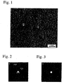
- the transmission electron photomicrograph of the TiSiN coating film is shown in Fig. 1.
- Figs. 2 and 3 show the electron beam diffraction photomicrographs of crystal structures in regions 1 and 2 in Fig. 1 taken under the conditions of a camera length of 50 cm and a beam diameter of 2 nm to 5 nm.
- the Si-containing coating film of the present invention has a crystalline phase and an amorphous or microcrystalline phase.
- Figs. 4 and 5 show the energy-dispersive, quantitative analysis results of the regions 1 and 2 in Fig. 1. The quantitative analysis of each region was conducted in a 1-nm-square region.
- Figs. 4 and 5 show that the crystalline region 1 contains 8 atomic % of Si, while the amorphous or microcrystalline phase 2 contains 26 atomic % of Si, both based on the metallic elements. It is thus clear from Figs. 4 and 5 that the concentration of Si in the amorphous or microcrystalline phase 2 is as high as three times or more that in the matrix crystalline phase 1 in this sample, meaning that Si exists predominantly in the amorphous or microcrystalline phase 2.
- the ratio of atomic % of Si in the in the amorphous or microcrystalline phase 2 to that in the matrix crystalline phase 1 is between 1.5:1 and 20:1, preferably between 1.8:1 and 10:1 (for example between 2:1 and 8:1, or between 3:1 and 7:1), and more preferably between 2:1 and 5:1 (for example between 3:1 and 5:1). Particularly favoured examples incude ratios of between 2:1 and 4:1 and between 2.5:1 and 3.5:1.
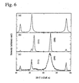
- Fig. 6 shows X-ray diffraction patterns of a TiSiN coating film (b) formed in COMPARATIVE EXAMPLES, and the above TiSiN coating film (c) formed by the method of the present invention (EXAMPLE 4), respectively.
- the method of forming the TiSiN coating film (b) in COMPARATIVE EXAMPLE 5 is described in "Surface and Coating Technology," 133-134(2000), pp. 307-313.
- (a) in Fig. 6 shows an X-ray diffraction pattern of a cutting tool substrate of cemented carbide. It is clear from Fig. 6 that a peak at a (200) face in an X-ray diffraction pattern is much broader in the Si-containing coating film (c) of the present invention than in the conventional Si-containing coating film (b).
- the crystalline region 1 has an NaCl-type crystal structure having an fcc structure, and that though a diffraction peak at the (200) face is broad by a residual stress in the Si-containing coating film, a face gap does not change largely by the addition of Si. It is thus confirmed from these results that the crystalline region 1 comprises TiSiN, in which a small amount of Si substitutes for Ti.
- the Si-containing coating film of the present invention preferably has the maximum peak in the intensity of X-ray diffraction at the (200) face, because the Si-containing coating film predominantly oriented in the (200) face has the least lattice defects and thus excellent oxidation resistance.
- the Si-containing coating film containing a high-Si-concentration, amorphous or microcrystalline phase and a low-Si-concentration, crystalline phase can be formed from Si, one or more metallic elements selected from the group consisting of the metallic elements of Groups 4a, 5a and 6a of the Periodic Table and Al, more preferably, one or more metallic elements selected from the group consisting of Si and Ti, Al and Cr; and one or more non-metallic elements selected from the group consisting of N, B, C and O. Even if an extremely small amount of Si is contained in the Si-containing coating film, an Si-concentrated amorphous or microcrystalline phase can be dispersed in the Si-containing coating film.
- an area ratio of the high-Si-concentration, amorphous or microcrystalline phase to the low-Si-concentration, crystalline phase is 5:95 to 50:50 in a transmission electron photomicrograph of the Si-containing coating film.
- the concentration of Si is 5 to 40 atomic %, preferably 10 to 20 atomic % based on the total amount of the metalloid elements.
- the cutting tool can exhibit stable cutting performance.
- an extremely fine Si oxide is formed from Si predominantly concentrated in the high-Si-concentration, amorphous or microcrystalline phase.
- the fine silicon oxide functions as a barrier to the inward diffusion of oxygen, thereby contributing to a significant improvement in oxidation resistance.
- the Si-containing coating film with a structure having a high-Si-concentration, amorphous or microcrystalline phase and a low-Si-concentration, crystalline phase, both having the same elements has less lattice defects in boundaries therebetween than a coating film having an independent phase such as silicon nitride, etc.
- the former is better than the latter in preventing the inward diffusion of oxygen.
- an arc discharge ion-plating method that can form a coating film with a remaining compressive stress at a relatively low temperature, from the viewpoint of a thermal influence on the cutting tool substrate, the fatigue strength of the cutting tool, the adhesion of a coating film to the cutting tool, etc.
- the arc discharge ion-plating method for forming the Si-containing coating film having a high-Si-concentration, amorphous or microcrystalline phase and a low-Si-concentration, crystalline phase on the cutting tool substrate via the first hard coating film may be carried out, for instance, as follows: First, a furnace is evacuated to vacuum of 3 x 10 -5 Pa, and the cutting tool substrate is heated with a heater.
- an alloy target for an aimed coating film composition is placed on a plurality of cathodes as evaporation sources for arc discharge in the furnace, and ionized by arc discharge to generate an atmosphere containing various kinds of metal ions and a reaction gas such as nitrogen, in which the cutting tool substrate is ion-plated.
- a bias voltage applied to the cutting tool substrate to control ion energy at the time of forming the Si-containing coating film.
- the level of ion energy for ion plating is determined mainly by a combination of the bias voltage applied to the cutting tool substrate and the reaction gas.
- the bias voltage applied to the cutting tool substrate may be different levels of negative bias voltage or bias voltage periodically changing between negative and positive.
- bias voltage induces a periodic change in the ion energy in the Si-containing coating film, thereby forming phases of different Si concentrations in the same Si-containing coating film.
- This periodic change of ion energy is important in the present invention.
- Various factors such as bias voltage, reaction pressure and temperature, etc. contribute to the periodic change of ion energy.
- the difference in the Si concentration in the Si-containing coating film may also change depending on the temperature of the substrate. Specifically, the high-Si-concentration, amorphous or microcrystalline phase would less likely be formed in the Si-containing coating film at temperatures over 500°C, even if other parameters than the temperature were optimized. Because the temperature of the substrate tends to be elevated as the bias voltage increases, a device for cooling the cutting tool substrate may be required when the materials of the cutting tool substrate limit the temperature thereof.
- the first hard coating film it may be formed by an arc discharge ion-plating method without changing ion energy throughout the process.
- the coating film of the present invention may be effectively applied to cutting tool substrates of high-speed tool steel, it is particularly effective when applied to end mills and inserts of cemented carbide capable of cutting works at higher speeds.
- the coating films of EXAMPLES 1-27 shown in Table 1 were formed on cutting tool substrates under the following conditions: Temperature of substrate: 350°C to 540°C; Pressure of reaction gas: 5 Pa; Bias pulse voltage: Negative bias voltage: 300 V; Positive bias voltage: 20 V; Term of negative bias voltage: 80% Term of positive bias voltage: 20%; and Frequency of bias voltage: 15 kHz.
- Table 1 Ex. No. Si-Containing Coating Film (Second Coating Film) First Coating Film Square End Mill Milling Insert Composition (atomic %) Av.
- Table 1 shows the composition and average grain size of the Si-containing coating film in each sample.
- the Si-containing coating film had a microcrystalline structure composed of ultra-fine crystal grains in EXAMPLES except for EXAMPLES 3, 8 and 25.
- Table 1 does not show atomic ratios of the metallic elements to the non-metallic elements, they are not necessarily 1:1.
- Table 1 also shows the cutting test results with the coated end mills and the coated milling inserts. With respect to each square end mill, a wear depth of a flank was measured at a cutting length of 200 m. With respect to each insert, a cutting time was measured until it was broken. The cutting conditions were as follows:
- Table 1 shows that stable cutting was performed even at a high cutting speed in EXAMPLES 1-27.
- EXAMPLES 1 to 3 in which Si was added to Cr to change an average grain size, the finer the average grain size, the higher wear resistance the cutting tools had.
- EXAMPLES 4 to 8 in which various amounts of Si was added to Ti, all cutting tools had excellent cutting performance.
- EXAMPLES 9 to 12 in which Si was added to Al, all coated cutting tools showed the same wear resistance as those of EXAMPLES 4 to 8 in which Si was added to Ti.
- the coated cutting tools of EXAMPLES 13 to 18 containing three kinds of elements had excellent cutting performance and similarly good wear resistance.
- EXAMPLES 19 to 22 containing Si and Nb, V, Zr or Mo all coated cutting tools had excellent cutting performance and similar wear resistance.
- the coated cutting tool of EXAMPLE 25 had a multilayer film of an fcc crystal structure of (CrSi)BN and a hcp crystal structure of (CrSi) 2 BN with excellent results.
- the coated cutting tools of EXAMPLES 26 and 27 in which oxygen or boron was added to a CrSiN coating film had better results than the conventional coated cutting tools. In all of EXAMPLES 1-27, a high-Si-concentration, amorphous or microcrystalline phase and a low-Si-concentration, crystalline phase were observed in the Si-containing coating film.
- coating films having compositions shown in Table 2 were formed by a conventional method using targets of various kinds of alloys as evaporation sources of elements and an N 2 gas as a reaction gas in the same arc discharge ion-plating device as in EXAMPLE 1 under the following coating conditions:
- the amount of Si was 15 atomic % in the coating film, and the coating film was a simple solid solution layer without segregation of Si.
- a ratio of Ti to Al in the TiAl coating film was 1:1.
- Cutting performance was evaluated under the same cutting conditions as in EXAMPLES. The evaluation results are shown in Table 2. Table 2 COM. EX.
- COMPARATIVE EXAMPLE 4 in which Si was added to a TiAlN coating film, the addition of Si improved the oxidation resistance and hardness of the coating film, though it increased a compressive stress such that the thickness of the film was at most 2 ⁇ m, failing to provide a substantial improvement in the cutting performance of the cutting tool with a TiAlN film. Since the coated cutting tools of COMPARATIVE EXAMPLES 5 and 6 were formed by the conventional method, the segregation of Si and an amorphous or microcrystalline phase were not observed in the coating film. The peeling of the coating film occurred at the initial cutting stage because of remarkable brittleness of Si.
- COMPARATIVE EXAMPLE 7 had extremely low oxidation resistance, failing to exhibit sufficient cutting performance under severe cutting conditions such as high-speed cutting.
- COMPARATIVE EXAMPLE 8 also yielded extremely poorer results than EXAMPLES.
- COMPARATIVE EXAMPLES 9 and 10 provided a CrSi-based simple solid solution layer having much shorter life than those of EXAMPLES.
- the present invention provides a cutting tool with a coating film having higher hardness than that of the conventional TiAlN coating film made by simply adding Si, thereby exhibiting sufficient cutting performance, particularly excellent oxidation resistance and wear resistance, even in a high-speed cutting operations. Further, the coated cutting tool of the present invention can be satisfactorily used with high performance even under severe cutting conditions such as at high-speed cutting and dry cutting.
Description
- The present invention relates to a multilayer-coated cutting tool used for cutting metallic materials, etc., particularly to a multilayer-coated cutting tool with improved wear resistance and oxidation resistance.
- Due to an increasing demand for a higher efficiency of cutting, high-speed machining centers have come into wide use, resulting in a trend of a higher cutting speed. According to this trend, it has become common to coat cutting tools with TiAlN having an improved oxidation resistance in place of TiN and TiCN.
- To cope with further increase in the speed of the cutting operations, various improvements are proposed on the coatings of cutting tools. For instance, Japanese Patent 2,793,773 proposes the addition of Si to a TiAlN coating film to improve its oxidation resistance, and Japanese Unexamined Patent Publication Nos. 8-118106 and 9-11004 propose the addition of Si to a Ti-based coating film.
- However, the mere addition of Si to the conventional coating film of TiAlN can improve oxidation resistance at most less than 1.2 times, failing to meet the present demand of higher cutting speed, though it produces some effects for a general cutting purpose. Further, though the addition of Si to a Ti-based hard coating film can slightly improve its oxidation resistance, it cannot sufficiently improve a static wear resistance of the coating film, resulting in a coated cutting tool not showing a sufficient improvement. This appears to be caused by the fact that Si added to the coating film forms a simple hard solid solution phase in which Si atoms substitute for Ti atoms to provide only solid-solution strengthening.
- Further, the coating film simply containing Si is more brittle by remarkably large compressive stress than a coating film containing no Si, and this excessive compressive stress makes the coating film prone to peel off from the cutting tool substrate immediately after the coating film is formed. Accordingly, the Si-containing coating films have not practically been applied to the cutting tools so far. As works become harder and the cutting conditions become severer, abnormal wear and fracture are caused by the peeling and oxidation of the coating film, resulting in failure to use cutting tools with Si-containing coating films for practical applications. Thus, sufficient improvement has not been achieved so far in the coating films of cutting tools to provide cutting performance necessary for high-speed cutting operations.
- Accordingly, an object of the present invention is to provide a cutting tool with an Si-containing coating film having drastically improved wear resistance and oxidation resistance without sacrificing adhesion to the cutting tool substrate, thereby fully exhibiting its own characteristics so that the cutting tool is highly suitable for high-speed cutting operations.
- In view of the fact that an Si-containing coating film formed on a cutting tool substrate has extremely higher compressive stress than a coating film not containing Si, and that the Si-containing coating film sometimes peels off during cutting operations due to an excessive compressive stress, failing to apply the Si-containing coating film to the cutting tool, the Si-containing coating film is desirably used in combination with another hard coating film having excellent adhesion to the substrate. By controlling the structure and crystal form of the Si-containing coating film itself, the residual compressive stress of the Si-containing coating film can be reduced, further improving the adhesion thereof to the cutting tool substrate. Further, by controlling the crystal form of the Si-containing coating film, the hardness of the coating film can be extremely increased, thereby further improving the wear resistance of the coated cutting tool. It has also been found that the oxidation resistance of the Si-containing coating film can be remarkably improved by controlling the crystal form thereof.
- Most of presently available multi-element nitrides such as TiAlN or the like form nitrides having a cubic NaCl-type crystal structure, and when Si is added to TiAlN, Si substitutes for a Ti atom in TiAlN to generate a lattice strain owing to a difference in an atom radius between Si and Ti, resulting in increase in a residual compressive stress. As the amount of Si added increases, the compressive stress excessively increases. It has thus been impossible to add Si to multi-element nitrides such as TiAlN, to such an extent that Si can provide sufficient effects.
- As a result of research in view of the above problems, the inventors have found that the Si-containing coating film comprising Si and one or more metallic elements of Groups 4a, 5a and 6a and Al can be provided with reduced stress and improved wear resistance as well as improved adhesion to the cutting tool substrate, by making the Si-containing coating film have a structure in which Si-rich, hard crystal grains are dispersed in a matrix constituted by a phase containing a relatively small amount of Si and having a small compressive stress.
- Thus, the multilayer-coated cutting tool according to the present invention is characterized by the features described in
Claim 1. - The second hard coating film preferably has an average grain size of not more than 50 nm. The second hard coating film preferably comprises Si3N4 and/or Si as a single phase.
- In one embodiment, the second hard coating film preferably contains a combination of Cr and Si or a combination of Ti and Si as metallic elements.
- In a further embodiment, the second hard coating film contains boron in the form of a boron nitride. In a still further embodiment, the second hard coating film is a multilayer coating film comprising at least two or more of a CrSiN layer, a (CrSi)2N layer, a CrSiBN layer, and a (CrSi)2BN layer.
- In a still further embodiment, the first hard coating film preferably contains a combination of Ti and Al or a combination of Cr and Al as metallic elements.
- In a still further embodiment, the first hard coating film comprises Al partially replaced by at least one element selected from the group consisting of Si, Mg, Ca, Sr, Li, K and Y in a range of 0.5 atomic % to 30 atomic %.
- In a still further embodiment, both the first and second hard coating films are formed by an arc discharge ion-plating method. Both the first and second hard coating films inevitably contain a plurality of droplet particles.
- The cutting tool substrate may be an end mill or an insert of cemented carbide.
-
- Fig. 1 is a transmission electron photomicrograph showing a lattice image of an Si-containing coating film having a composition of TiSiN in accordance with the present invention;
- Fig. 2 is a microscopic electron beam diffraction image showing a crystal structure of a high-Si-concentration phase in Fig. 1;
- Fig. 3 is a microscopic electron beam diffraction image showing a crystal structure of a low-Si concentration phase in Fig. 1;
- Fig. 4 shows the energy dispersion-type, quantitative analysis results of an amorphous or microcrystalline phase in the Si-containing coating film of Fig. 1;
- Fig. 5 shows the energy dispersion-type, quantitative analysis results of a crystalline phase in the Si-containing coating film of Fig. 1; and
- Fig. 6 is a graph showing X-ray diffraction patterns of (a) a cutting tool substrate of cemented carbide, (b) an Si-containing coating film of TiSiN produced by a conventional method, and (c) an Si-containing coating film of TiSiN produced by the method of the present invention.
- The multilayer-coated cutting tool of the present invention which is given in
claim 1 comprises a multilayer coating film having a first hard coating film formed on the cutting tool substrate and based on Ti, Al and/or Cr as metallic elements, and N, B, C and/or O as non-metallic elements, and a second hard coating film formed on the first hard coating film and based on Si and other metallic elements and N, B, C and/or O as non-metallic elements. The important feature of the present invention is that the second hard coating film is a composition-segregated polycrystalline film comprising a phase having a relatively high Si concentration and a phase having a relatively low Si concentration. The second hard coating film may be called "Si-containing coating film," because it is characterized by the inclusion of Si. - The Si-containing coating film having different phases containing different amounts of Si can be formed not by conventional coating methods but by methods of sequentially or periodically changing ion energy during coating operations. Such methods include, for example, a method in which bias pulse voltage applied to the cutting tool substrate is sequentially or periodically changed between positive voltage and negative voltage during coating operations, and a method in which pulse bias voltage is changed similarly. The positive pulse voltage and the negative pulse voltage are alternating, and their levels and terms are changed depending on the desired composition of the Si-containing coating film. The sequential or periodic change of ion energy changes the diffusion depth of ions on a surface of the cutting tool substrate, to generate unevenness in the concentration of Si. A coating temperature is also an important factor controlling the diffusion depth of ions and thus controlling the crystal form, particularly grain size, of the Si-containing coating film.
- The lower the coating temperature, the finer the resultant crystal grains, increasing the hardness of the Si-containing coating film and making grain boundaries denser, thereby preventing the oxidation of the Si-containing coating film due to the diffusion of oxygen in the grain boundaries to improve the oxidation resistance of the Si-containing coating film. Specifically, the phase having a relatively high Si concentration is formed by a low-temperature ion plating as an amorphous or microcrystalline phase in the Si-containing coating film. This high-Si-concentration phase preferably comprises nanometer-size crystal grains having an average grain size of not more than 50 nm, which provide particularly excellent effects of improving oxidation resistance. The crystal grains of the high-Si-concentration phase are so small that the high-Si-concentration phase may be called "amorphous or microcrystalline."
- Si-rich crystal grains are turned to an amorphous or microcrystalline phase at a coating temperature of 350°C to 400°C, resulting in a structure having remarkably decreased lattice defects by good arrangement of a crystalline phase with an amorphous or microcrystalline phase, further reducing the diffusion of oxygen. This further improves the oxidation resistance of the Si-containing coating film and makes the grain size finer to increase the hardness of the coating film, resulting in forming a coating film capable of providing a cutting tool with sufficient cutting performance. Since the Si content is relatively small in the matrix phase (low-Si-concentration phase), the Si-containing coating film has good adhesion to the underlying hard coating film.
- An Si3N4 phase and/or an Si phase exists in the Si-containing coating film formed at a coating temperature of 300°C to 350°C. The existence of these phases can be confirmed by examining by ESCA whether or not there is a peak in its binding energy. In a case where the Si3N4 phase and the Si phase exist in the coating film, the coating film tends to be provided with increased hardness and wear resistance because of the lattice strain caused by these phases. However, the Si-containing coating film having lattice strain tends to have slightly decreased oxidation resistance presumably due to the fact that the diffusion of oxygen is accelerated through the grain boundaries.
- What is important in the Si-containing coating film is its structure and crystal form, but not the types of other components than Si. That is, various elements can be combined with Si. The inventors' research has revealed that the second hard coating film containing Ti and Si as metallic elements shows the most excellent dynamic oxidation resistance in cutting operations. In this case, titanium oxide having a lower free energy of formation than a silicon oxide is formed in a surface of the Si-containing coating film during the cutting operations, so that Ti is diffused outward in the Si-containing coating film to form a powdery TiO layer in a surface area of the Si-containing coating film, while Si in the surface is diffused inward to form an extremely dense silicon oxide layer directly under the TiO layer. Why the coating film shows excellent dynamic oxidation resistance is presumably due to the fact that the powdery TiO contributes to lubrication, and that a dense Si oxide layer has excellent adhesion to an underlying layer and functions as a barrier to the diffusion of oxygen. Because the dynamic oxidation resistance is particularly important in the high-speed cutting of high-hardness steel, the coating film containing Ti and Si achieves the longest life.
- In a case where the Si-containing coating film contains Cr and Si as metallic elements, the self-lubrication effect of Cr remarkably suppresses galling at cutting edges at the time of cutting steel, etc., thereby providing a work with an excellent machined surface. Particularly in the case of cutting carbon steel prone to be subjected to galling, this coating film achieves the best-machined surface and the longest life. It is also confirmed that a (CrSi)2N layer is smaller than a CrSiN layer in a friction coefficient to carbon steel, and that the adoption of the (CrSi)2N layer can therefore further suppress the galling to elongate the life of the cutting tool.
- Although the Si-containing coating film can be provided with reduced internal stress by controlling the structure and crystal form, a single-layer, Si-containing coating film tends to peel off from the cutting tool substrate, when it is subjected to heavy cutting operations. Therefore, the Si-containing coating film should have an underlying coating film (first hard coating film) having excellent adhesion to the cutting tool substrate. Although the composition of this adhesion-providing underlying layer is not restrictive as long as it comprises one or more metallic elements selected from the group consisting of Ti, Al and Cr, and one or more non-metallic elements selected from the group consisting of N, B, C and O, a hard TiAl-based coating film or a hard CrAl-based coating film are preferable, because they can improve the high-speed cutting performance of the cutting tool to high-hardness steel than the Ti-based coating film. The Ti-based coating film can provide a particularly stable cutting performance in heavy cutting operations.
- Of course, in the first hard coating film, Ti may be partially replaced by the elements of Groups 4a, 5a and 6a of the Periodic Table, as is generally practiced. Moreover, the replacement of Ti by Si, Mg, Ca, Sr, Li, K and Y in a range of 0.5 atomic % to 30 atomic % can extremely elongate the life. Like the phenomenon described above, these elements diffuse in the coating film toward the surface to form oxides during cutting operations, and the oxides of these elements have particularly low melting points, thereby forming a liquid phase during cutting to remarkably reduce cutting resistance and temperature, resulting in providing a lubrication effect and thus achieving a long life. The replacement of Ti by Si enhances the oxidation resistance of the coating film, thereby achieving a longer life at the time of cutting high-hardness materials at high-cutting speeds. When the second hard coating film contains Si, Si may be segregated or dissolved in a solid solution under other general coating conditions than that for the formation of the first hard coating film.
- The addition of boron to the first hard coating film and/or the second hard coating film is effective to improve a cutting performance. Particularly in a case where the coating film is formed under high ion energy conditions, boron exists as BN in the coating film, improving the self-lubrication of the coating film to reduce cutting resistance, resulting in achieving a long life. The existence of a BN phase can be confirmed by ESCA.
- With this structure, the multilayer-coated cutting tool of the present invention has extremely improved cutting performance, because its multilayer coating film is provided with improved oxidation resistance and hardness without peeling off from the cutting tool substrate, even under severe cutting conditions such as cutting at high speeds and high-hardness materials.
- Taking an amorphous or microcrystalline phase in a TiSiN coating film as a second hard coating film for example, the requirements of the present invention will be described in detail. The composition of TiSiN and the formation method of the TiSiN coating film are the same as in EXAMPLE 4. The transmission electron photomicrograph of the TiSiN coating film is shown in Fig. 1. Figs. 2 and 3 show the electron beam diffraction photomicrographs of crystal structures in
regions - It is clear from Figs. 1-3 that the Si-containing coating film of the present invention has a crystalline phase and an amorphous or microcrystalline phase. Figs. 4 and 5 show the energy-dispersive, quantitative analysis results of the
regions crystalline region 1 contains 8 atomic % of Si, while the amorphous ormicrocrystalline phase 2 contains 26 atomic % of Si, both based on the metallic elements. It is thus clear from Figs. 4 and 5 that the concentration of Si in the amorphous ormicrocrystalline phase 2 is as high as three times or more that in thematrix crystalline phase 1 in this sample, meaning that Si exists predominantly in the amorphous ormicrocrystalline phase 2. - Typically, the ratio of atomic % of Si in the in the amorphous or
microcrystalline phase 2 to that in thematrix crystalline phase 1 is between 1.5:1 and 20:1, preferably between 1.8:1 and 10:1 (for example between 2:1 and 8:1, or between 3:1 and 7:1), and more preferably between 2:1 and 5:1 (for example between 3:1 and 5:1). Particularly favoured examples incude ratios of between 2:1 and 4:1 and between 2.5:1 and 3.5:1. - Fig. 6 shows X-ray diffraction patterns of a TiSiN coating film (b) formed in COMPARATIVE EXAMPLES, and the above TiSiN coating film (c) formed by the method of the present invention (EXAMPLE 4), respectively. The method of forming the TiSiN coating film (b) in COMPARATIVE EXAMPLE 5 is described in "Surface and Coating Technology," 133-134(2000), pp. 307-313. Incidentally, (a) in Fig. 6 shows an X-ray diffraction pattern of a cutting tool substrate of cemented carbide. It is clear from Fig. 6 that a peak at a (200) face in an X-ray diffraction pattern is much broader in the Si-containing coating film (c) of the present invention than in the conventional Si-containing coating film (b).
- It is also clear from the electron beam diffraction image of the
region 1 in Fig. 1 and the X-ray diffraction pattern (c) shown in Fig. 6 that thecrystalline region 1 has an NaCl-type crystal structure having an fcc structure, and that though a diffraction peak at the (200) face is broad by a residual stress in the Si-containing coating film, a face gap does not change largely by the addition of Si. It is thus confirmed from these results that thecrystalline region 1 comprises TiSiN, in which a small amount of Si substitutes for Ti. The Si-containing coating film of the present invention preferably has the maximum peak in the intensity of X-ray diffraction at the (200) face, because the Si-containing coating film predominantly oriented in the (200) face has the least lattice defects and thus excellent oxidation resistance. - The Si-containing coating film containing a high-Si-concentration, amorphous or microcrystalline phase and a low-Si-concentration, crystalline phase can be formed from Si, one or more metallic elements selected from the group consisting of the metallic elements of Groups 4a, 5a and 6a of the Periodic Table and Al, more preferably, one or more metallic elements selected from the group consisting of Si and Ti, Al and Cr; and one or more non-metallic elements selected from the group consisting of N, B, C and O. Even if an extremely small amount of Si is contained in the Si-containing coating film, an Si-concentrated amorphous or microcrystalline phase can be dispersed in the Si-containing coating film.
- In a preferred embodiment, an area ratio of the high-Si-concentration, amorphous or microcrystalline phase to the low-Si-concentration, crystalline phase is 5:95 to 50:50 in a transmission electron photomicrograph of the Si-containing coating film. In the high-Si-concentration, amorphous or microcrystalline phase, the concentration of Si is 5 to 40 atomic %, preferably 10 to 20 atomic % based on the total amount of the metalloid elements.
- With the Si-containing coating film having a high-Si-concentration, amorphous or microcrystalline phase and a low-Si-concentration, crystalline phase, the cutting tool can exhibit stable cutting performance. With respect to a static oxidation mechanism, an extremely fine Si oxide is formed from Si predominantly concentrated in the high-Si-concentration, amorphous or microcrystalline phase. The fine silicon oxide functions as a barrier to the inward diffusion of oxygen, thereby contributing to a significant improvement in oxidation resistance. Further, the Si-containing coating film with a structure having a high-Si-concentration, amorphous or microcrystalline phase and a low-Si-concentration, crystalline phase, both having the same elements, has less lattice defects in boundaries therebetween than a coating film having an independent phase such as silicon nitride, etc. As a result, the former is better than the latter in preventing the inward diffusion of oxygen.
- As a result of analysis of dynamic oxidation, namely an oxidation behavior in cutting operations, it has been found that a surface portion of the Si-containing coating film of the cutting tool is turned to an Si-concentrated oxide film with Fe deposited under wearing action during the cutting operations, and that the resultant Si-concentrated oxide film prevents oxidation while exhibiting a lubrication effect. It is presumed that these synergy effects remarkably improve high-speed cutting performance of the cutting tool.
- To carry out coating of the cutting tool, it is desirable to use an arc discharge ion-plating method that can form a coating film with a remaining compressive stress at a relatively low temperature, from the viewpoint of a thermal influence on the cutting tool substrate, the fatigue strength of the cutting tool, the adhesion of a coating film to the cutting tool, etc.
- The arc discharge ion-plating method for forming the Si-containing coating film having a high-Si-concentration, amorphous or microcrystalline phase and a low-Si-concentration, crystalline phase on the cutting tool substrate via the first hard coating film may be carried out, for instance, as follows: First, a furnace is evacuated to vacuum of 3 x 10⁻⁵ Pa, and the cutting tool substrate is heated with a heater. After the cutting tool substrate is cleaned and activated by Ar ions, an alloy target for an aimed coating film composition is placed on a plurality of cathodes as evaporation sources for arc discharge in the furnace, and ionized by arc discharge to generate an atmosphere containing various kinds of metal ions and a reaction gas such as nitrogen, in which the cutting tool substrate is ion-plated. In this case, it is necessary to periodically change a bias voltage applied to the cutting tool substrate to control ion energy at the time of forming the Si-containing coating film.
- More specifically, the level of ion energy for ion plating is determined mainly by a combination of the bias voltage applied to the cutting tool substrate and the reaction gas. The bias voltage applied to the cutting tool substrate may be different levels of negative bias voltage or bias voltage periodically changing between negative and positive. Such bias voltage induces a periodic change in the ion energy in the Si-containing coating film, thereby forming phases of different Si concentrations in the same Si-containing coating film. This periodic change of ion energy is important in the present invention. Various factors such as bias voltage, reaction pressure and temperature, etc. contribute to the periodic change of ion energy.
- The difference in the Si concentration in the Si-containing coating film may also change depending on the temperature of the substrate. Specifically, the high-Si-concentration, amorphous or microcrystalline phase would less likely be formed in the Si-containing coating film at temperatures over 500°C, even if other parameters than the temperature were optimized. Because the temperature of the substrate tends to be elevated as the bias voltage increases, a device for cooling the cutting tool substrate may be required when the materials of the cutting tool substrate limit the temperature thereof.
- With respect to the first hard coating film, it may be formed by an arc discharge ion-plating method without changing ion energy throughout the process.
- Though the coating film of the present invention may be effectively applied to cutting tool substrates of high-speed tool steel, it is particularly effective when applied to end mills and inserts of cemented carbide capable of cutting works at higher speeds.
- The present invention will be described in further detail referring to EXAMPLES below without intention of restricting the present invention thereto.
- Using various kinds of alloy targets as evaporation sources of elements and N2 as a reaction gas in an arc discharge ion-plating device, the coating films of EXAMPLES 1-27 shown in Table 1 were formed on cutting tool substrates under the following conditions:
Temperature of substrate: 350°C to 540°C; Pressure of reaction gas: 5 Pa; Bias pulse voltage: Negative bias voltage: 300 V; Positive bias voltage: 20 V; Term of negative bias voltage: 80% Term of positive bias voltage: 20%; and Frequency of bias voltage: 15 kHz. Table 1 Ex. No. Si-Containing Coating Film (Second Coating Film) First Coating Film Square End Mill Milling Insert Composition (atomic %) Av. Grain Size (nm) Composition (atomic %) Wear VB (mm) Cutting Time (hr) 1 (Cr90Si10)N 150 (Ti50Al50)N 0.05 2.2 2 (Cr90Si10)N 40 (Ti50Al50)N 0.02 3.5 3 (Cr90Si10)N* 10 (Ti50Al50)N 0.02 4.1 4 (Ti75Si25)N 40 (Ti50Al50)N 0.02 2.5 5 (Ti85Si15)N 35 (Ti50Al50)N 0.02 2.4 6 (Ti85Si15)NO 35 (Cr50-Al50)N 0.02 3.0 7 (Ti85Si15)N 35 (Ti46Al50Mg4)N 0.01 3.6 8 (Ti85Si15)BN* 20 (Ti42Al45Mg13)N 0.01 4.2 9 (Al85Si15)N 200 (Ti50Al50)N 0.05 2.4 10 (Al70Si30)N 35 (Ti50Al50)N 0.03 2.9 11 (Al50Si50)N 35 (Ti50Al50)N 0.08 1.6 12 (Al40Si60)N 35 (Ti50Al50)N 0.08 1.4 13 (Ti70Al15Si15)N 200 (Ti50Al50)N 0.04 2.1 14 (Cr78Al10Si12)N 150 (Ti50Al50)N 0.03 2.3 15 (Ti85Nb10Si5)N 50 (Ti50Al50)N 0.04 2.5 16 (Ti80Al5Si15)N 35 (Ti50Al50)N 0.05 1.9 17 (Cr94Si5W1)N 20 (Ti50Al50)N 0.07 1.5 18 (Ti85Si10Y5)N 20 (Ti50Al50)N 0.04 2.1 19 (Nb95Si5)N 20 (Ti50Al50)N 0.05 1.9 20 (V95Si5)N 50 (Ti50Al50)N 0.05 1.9 21 (Zr95Si5)N 100 (Ti50Al50)N 0.07 1.6 22 (Mo95Si5)N 100 (Ti50Al50)N 0.07 1.5 23 (Ti75Si25)NO 100 TiN 0.04 2.7 24 (Ti75Si25)CN 100 TiN 0.03 2.3 25 (Cr95Si5)BN* (Cr95Si5)2BN* 20 TiN 0.02 3.5 26 (Cr95Si5)ON 80 (Ti50Al50)N 0.09 2.3 27 (Cr75Si25)BN 80 (Ti50Al50)N 0.07 3.9 Note *: Amorphous phase formed at 350°C. - While rotating each substrate at a revolution of 5 m-1, electric current of 30 A was applied to each evaporation source arranged on one side, and electric current of 300 A was applied to each evaporation source opposing thereto to form a coating film. Using six-edge square end mills of cemented carbide each having an outer diameter of 8 mm and milling inserts of cemented carbide as cutting tool substrates, a coating film was formed on each substrate in a total thickness of 4 µm to 6 µm. Incidentally, the first hard coating film was formed by a conventional method at a constant bias voltage. Multi-layer coating films were formed together with a TiAlN film, if necessary.
- Table 1 shows the composition and average grain size of the Si-containing coating film in each sample. The Si-containing coating film had a microcrystalline structure composed of ultra-fine crystal grains in EXAMPLES except for EXAMPLES 3, 8 and 25.
- Though Table 1 does not show atomic ratios of the metallic elements to the non-metallic elements, they are not necessarily 1:1. Table 1 also shows the cutting test results with the coated end mills and the coated milling inserts. With respect to each square end mill, a wear depth of a flank was measured at a cutting length of 200 m. With respect to each insert, a cutting time was measured until it was broken. The cutting conditions were as follows:
- For six-edge square end mills of cemented carbide
Cutting method: side cutting,
Work: SKD11 (hardness: HRC 52), width 150 mm x length 250 mm,
Depth of cutting: 8 mm in axial direction, 0.2 mm in radial direction,
Cutting speed: 500 m/minute,
Feed: 0.07 mm/edge, and
Cutting oil: air blowing. - For milling inserts of cemented carbide
Cutting tool: EDEW15T4TN-15 (JIS B 4120),
Cutter: 63 mm in diameter,
Cutting method: chamfering,
Work: SKD61 (hardness: HRC 43),width 50 mm x length 250 mm,
Depth of cutting: 2.0 mm,
Cutting speed: 250 m/minute,
Feed: 0.5 mm/rev, and
Cutting oil: air blowing. - Table 1 shows that stable cutting was performed even at a high cutting speed in EXAMPLES 1-27. In EXAMPLES 1 to 3 in which Si was added to Cr to change an average grain size, the finer the average grain size, the higher wear resistance the cutting tools had. In EXAMPLES 4 to 8 in which various amounts of Si was added to Ti, all cutting tools had excellent cutting performance. In EXAMPLES 9 to 12 in which Si was added to Al, all coated cutting tools showed the same wear resistance as those of EXAMPLES 4 to 8 in which Si was added to Ti. The coated cutting tools of EXAMPLES 13 to 18 containing three kinds of elements had excellent cutting performance and similarly good wear resistance.
- In EXAMPLES 19 to 22 containing Si and Nb, V, Zr or Mo, all coated cutting tools had excellent cutting performance and similar wear resistance. The coated cutting tools containing O or C in addition to N in EXAMPLES 23 and 24 exhibited the same performance as that of other EXAMPLES. The coated cutting tool of EXAMPLE 25 had a multilayer film of an fcc crystal structure of (CrSi)BN and a hcp crystal structure of (CrSi)2BN with excellent results. The coated cutting tools of EXAMPLES 26 and 27 in which oxygen or boron was added to a CrSiN coating film had better results than the conventional coated cutting tools. In all of EXAMPLES 1-27, a high-Si-concentration, amorphous or microcrystalline phase and a low-Si-concentration, crystalline phase were observed in the Si-containing coating film.
- After conducting the same pretreatment as in EXAMPLE 1, coating films having compositions shown in Table 2 were formed by a conventional method using targets of various kinds of alloys as evaporation sources of elements and an N2 gas as a reaction gas in the same arc discharge ion-plating device as in EXAMPLE 1 under the following coating conditions:
- Temperature of substrate: 400°C;
- Pressure of reaction gas: 5 Pa; and
- Negative bias voltage:70 V.
- The amount of Si was 15 atomic % in the coating film, and the coating film was a simple solid solution layer without segregation of Si. A ratio of Ti to Al in the TiAl coating film was 1:1. Cutting performance was evaluated under the same cutting conditions as in EXAMPLES. The evaluation results are shown in Table 2.
Table 2 COM. EX. Composition Square End Mill Milling Insert Wear VB (mm) Cutting Time (hr) 1 TiN 5 m(1) 0.2 2 TiCN 80 m(2) 0.6 3 TiN-TiAlN 0.18 0.7 4 TiAlSiN 0.15 0.7 5 TiSiN Peeled Broken 6 TiAlN-TiSiN 0.14 0.9 7 TiZrN Peeled 0.1 8 TiN-AlN Multilayer Film 0.22 0.4 9 TiN-CrSiN 0.34 0.6 10 CrSiN Peeled 0.7 Note: (1) - Cutting could not be continued when a cutting length reached 5 m. (2) - Cutting could not be continued when a cutting length reached 80 m. - In COMPARATIVE EXAMPLE 4 in which Si was added to a TiAlN coating film, the addition of Si improved the oxidation resistance and hardness of the coating film, though it increased a compressive stress such that the thickness of the film was at most 2 µm, failing to provide a substantial improvement in the cutting performance of the cutting tool with a TiAlN film. Since the coated cutting tools of COMPARATIVE EXAMPLES 5 and 6 were formed by the conventional method, the segregation of Si and an amorphous or microcrystalline phase were not observed in the coating film. The peeling of the coating film occurred at the initial cutting stage because of remarkable brittleness of Si. The multiple-element coating film containing no Si in COMPARATIVE EXAMPLE 7 had extremely low oxidation resistance, failing to exhibit sufficient cutting performance under severe cutting conditions such as high-speed cutting. COMPARATIVE EXAMPLE 8 also yielded extremely poorer results than EXAMPLES. COMPARATIVE EXAMPLES 9 and 10 provided a CrSi-based simple solid solution layer having much shorter life than those of EXAMPLES.
- While the coated cutting tool of the present invention has been described with reference to the preferred embodiments, it should be understood that the present invention is not limited thereto. On the contrary, the present invention is intended to cover all alternatives, modifications and equivalents, which may be included within the spirit and scope of the invention as defined by the appended claims.
- As described above in detail, the present invention provides a cutting tool with a coating film having higher hardness than that of the conventional TiAlN coating film made by simply adding Si, thereby exhibiting sufficient cutting performance, particularly excellent oxidation resistance and wear resistance, even in a high-speed cutting operations. Further, the coated cutting tool of the present invention can be satisfactorily used with high performance even under severe cutting conditions such as at high-speed cutting and dry cutting.
Claims (14)
- A multilayer-coated cutting tool comprising
a cutting tool substrate, and
a multilayer coating film comprising
a first hard coating film formed on said substrate and
a second hard coating film formed on said first hard coating film,
said first hard coating film comprising
one or more metallic elements selected from the group consisting of Ti, Al and Cr, and
one or more non-metallic elements selected from the group consisting of N, B, C and O; and
said second hard coating film comprising
Si and one or more metallic elements selected from the group consisting of metallic elements of Groups 4a, 5a and 6a of the Periodic Table and Al, and
one or more non-metallic elements selected from the group consisting of N, B, C and O;
said second hard coating film being a composition-segregated polycrystalline film comprising
an amorphous or a microcrystalline phase having a high Si concentration of 5 to 40 atomic-% based on the total amount of the metalloid elements and
a crystalline phase having a low Si concentration at an atomic-% ratio between 1/1.5 and 1/20 relative to the high concentration of Si in the amorphous or microcrystalline phase. - The multilayer-coated cutting tool according to claim 1, wherein said second hard coating film has an average grain size of not more than 50 nm.
- The multilayer-coated cutting tool according to any one of claims 1-2, wherein said second hard coating film comprises Si3N4 and/or Si as a single phase.
- The multilayer-coated cutting tool according to any one of claims 1-3, wherein said second hard coating film contains Cr and Si as metallic elements.
- The multilayer-coated cutting tool according to any one of claims 1-3, wherein said second hard coating film contains Ti and Si as metallic elements.
- The multilayer-coated cutting tool according to any one of claims 1-5, wherein said second hard coating film contains boron in the form of a boron nitride.
- The multilayer-coated cutting tool according to any one of claims 1-6, wherein said second hard coating film is a multilayer coating film comprising at least two or more of a CrSiN layer, a (CrSi)2N layer, a CrSiBN layer, and a (CrSi)2BN layer.
- The multilayer-coated cutting tool according to any one of claims 1-7, wherein said first hard coating film contains Ti and Al as metallic elements.
- The multilayer-coated cutting tool according to any one of claims 1-7, wherein said first hard coating film contains Cr and Al as metallic elements.
- The multilayer-coated cutting tool according to any one of claims 1-9, wherein said first hard coating film comprises Al partially replaced by at least one element selected from the group consisting of Si, Mg, Ca, Sr, Li, K and Y in a range of 0.5 atomic % to 30 atomic %.
- The multilayer-coated cutting tool according to any one of claims 1-10, wherein both of said first and second hard coating films are formed by an arc discharge ion-plating method.
- The multilayer-coated cutting tool according to claim 11, wherein both of said first and second hard coating films inevitably contain droplet particles.
- The multilayer-coated cutting tool according to any one of claims 1-12, wherein said cutting tool substrate is an end mill of cemented carbide.
- The multilayer-coated cutting tool according to any one of claims 1-12, wherein said cutting tool substrate is an insert of cemented carbide.
Applications Claiming Priority (2)
| Application Number | Priority Date | Filing Date | Title |
|---|---|---|---|
| JP2000213536A JP3417907B2 (en) | 2000-07-13 | 2000-07-13 | Multi-layer coating tool |
| JP2000213536 | 2000-07-13 |
Publications (3)
| Publication Number | Publication Date |
|---|---|
| EP1174528A2 EP1174528A2 (en) | 2002-01-23 |
| EP1174528A3 EP1174528A3 (en) | 2004-05-06 |
| EP1174528B1 true EP1174528B1 (en) | 2006-01-04 |
Family
ID=18709274
Family Applications (1)
| Application Number | Title | Priority Date | Filing Date |
|---|---|---|---|
| EP01306046A Expired - Lifetime EP1174528B1 (en) | 2000-07-13 | 2001-07-13 | Multilayer-coated cutting tool |
Country Status (4)
| Country | Link |
|---|---|
| US (1) | US6586122B2 (en) |
| EP (1) | EP1174528B1 (en) |
| JP (1) | JP3417907B2 (en) |
| DE (1) | DE60116446T2 (en) |
Cited By (2)
| Publication number | Priority date | Publication date | Assignee | Title |
|---|---|---|---|---|
| DE112014001619B4 (en) | 2013-03-25 | 2018-06-14 | Kabushiki Kaisha Kobe Seiko Sho (Kobe Steel, Ltd.) | Hard material layer system with excellent wear resistance |
| US10487388B2 (en) | 2012-09-28 | 2019-11-26 | Walter Ag | Tool with TiAlCrSiN PVD coating |
Families Citing this family (81)
| Publication number | Priority date | Publication date | Assignee | Title |
|---|---|---|---|---|
| DE10233222B4 (en) * | 2001-07-23 | 2007-03-01 | Kabushiki Kaisha Kobe Seiko Sho (Kobe Steel, Ltd.), Kobe | Hard wear-resistant layer, method of forming same and use |
| EP1316627B1 (en) * | 2001-11-28 | 2006-04-05 | METAPLAS IONON Oberflächenveredelungstechnik GmbH | Hard coating coated parts |
| JP3996809B2 (en) * | 2002-07-11 | 2007-10-24 | 住友電工ハードメタル株式会社 | Coated cutting tool |
| SE526339C2 (en) * | 2002-09-04 | 2005-08-23 | Seco Tools Ab | Cut with durable refractory coating with composite structure |
| DK1422311T3 (en) * | 2002-11-19 | 2007-06-11 | Hitachi Tool Eng | Hard film and tool coated with hard film |
| US7211138B2 (en) * | 2003-02-07 | 2007-05-01 | Kabushiki Kaisha Kobe Seiko Sho (Kobe Steel, Ltd.) | Hard film, method of forming the same and target for hard film formation |
| JP4038448B2 (en) * | 2003-03-25 | 2008-01-23 | 株式会社神戸製鋼所 | Hard coating |
| US7226670B2 (en) | 2003-04-28 | 2007-06-05 | Oc Oerlikon Balzers Ag | Work piece with a hard film of AlCr-containing material, and process for its production |
| EP1536041B1 (en) * | 2003-11-25 | 2008-05-21 | Mitsubishi Materials Corporation | Coated cermet cutting tool with a chipping resistant, hard coating layer |
| JP2005271190A (en) * | 2003-12-05 | 2005-10-06 | Sumitomo Electric Hardmetal Corp | Surface coated cutting tool |
| JP2006118051A (en) * | 2003-12-18 | 2006-05-11 | Hitachi Tool Engineering Ltd | Method for producing hard film |
| CN100445023C (en) * | 2003-12-22 | 2008-12-24 | 三菱综合材料株式会社 | Surface-coated cermet cutting tool with hard coating layer having excellend chipping resistance |
| CN100419117C (en) * | 2004-02-02 | 2008-09-17 | 株式会社神户制钢所 | Hard laminated film, method of manufacturing the same and film-forming device |
| JP4704335B2 (en) * | 2004-03-18 | 2011-06-15 | 住友電工ハードメタル株式会社 | Surface coated cutting tool |
| EP1757388B1 (en) * | 2004-06-18 | 2015-11-04 | Mitsubishi Materials Corporation | Surface-coated cutware and process for producing the same |
| JP2006116831A (en) | 2004-10-22 | 2006-05-11 | Sony Corp | Printer and method of controlling it |
| EP1614655B2 (en) | 2004-06-18 | 2018-08-08 | Hitachi Tool Engineering Ltd. | Hard coating and its production method |
| KR101204184B1 (en) * | 2004-07-15 | 2012-11-23 | 오를리콘 트레이딩 아크티엔게젤샤프트, 트뤼프바흐 | High Oxidation Resistant Hard Coating for Cutting Tools |
| JP2006082208A (en) * | 2004-09-17 | 2006-03-30 | Sumitomo Electric Hardmetal Corp | Surface coated cutting tool |
| JP2006082209A (en) * | 2004-09-17 | 2006-03-30 | Sumitomo Electric Hardmetal Corp | Surface coated cutting tool |
| EP1842610B1 (en) * | 2004-12-28 | 2017-05-03 | Sumitomo Electric Hardmetal Corp. | Surface-coated cutting tool and process for producing the same |
| US7879443B2 (en) | 2005-02-10 | 2011-02-01 | Oc Oerlikon Trading Ag, Truebbach | High wear resistant triplex coating for cutting tools |
| JP4702520B2 (en) * | 2005-02-14 | 2011-06-15 | 三菱マテリアル株式会社 | Cutting tool made of surface-coated cemented carbide that provides excellent wear resistance with a hard coating layer in high-speed cutting of hardened steel |
| US7348074B2 (en) | 2005-04-01 | 2008-03-25 | Oc Oerlikon Balzers Ag | Multilayer hard coating for tools |
| SE529223C2 (en) | 2005-05-06 | 2007-06-05 | Seco Tools Ab | Coated cutting tool comprising hexagonal h- (Mel, Me2) X phase |
| US7537822B2 (en) * | 2005-05-26 | 2009-05-26 | Hitachi Tool Engineering, Ltd. | Hard-coated member |
| JP2007063650A (en) * | 2005-09-01 | 2007-03-15 | Osg Corp | Hard stacked film, and hard stacked film-coated tool |
| EP1783245B1 (en) * | 2005-11-04 | 2018-01-24 | Oerlikon Surface Solutions AG, Pfäffikon | Tool or wear part and pvd coating method to deposit a surface coating on a tool or wear part |
| JP4753249B2 (en) * | 2006-01-13 | 2011-08-24 | 株式会社神戸製鋼所 | Mold for glass molding |
| JP4844879B2 (en) * | 2006-06-30 | 2011-12-28 | 三菱マテリアル株式会社 | Surface coated cutting tool with excellent wear resistance with hard coating layer in high speed cutting of heat resistant alloy |
| JP4844880B2 (en) * | 2006-06-30 | 2011-12-28 | 三菱マテリアル株式会社 | Surface coated cutting tool with excellent wear resistance with hard coating layer in high speed cutting of heat resistant alloy |
| US20080014420A1 (en) * | 2006-07-11 | 2008-01-17 | Ion Technology (Hong Kong) Limited | Surface treatment for titanium or titanium-alloys |
| JP5096715B2 (en) * | 2006-09-21 | 2012-12-12 | 株式会社神戸製鋼所 | Hard coating and hard coating tool |
| DE102006046915C5 (en) * | 2006-10-04 | 2015-09-03 | Federal-Mogul Burscheid Gmbh | Piston ring for internal combustion engines |
| WO2008050384A1 (en) * | 2006-10-23 | 2008-05-02 | Osg Corporation | Hard laminated coating, tool covered with hard laminated coating, and method of forming coating |
| SE0700800L (en) * | 2006-12-15 | 2008-06-16 | Sandvik Intellectual Property | Coated cutting tool |
| SE0602814L (en) * | 2006-12-27 | 2008-06-28 | Sandvik Intellectual Property | Cutting tool with multilayer coating |
| CN101557897B (en) * | 2007-02-22 | 2011-09-07 | 三菱重工业株式会社 | Surface film member, process for rpoducing the surface covering member, cutting tool, and machine tool |
| US7960015B2 (en) | 2007-03-23 | 2011-06-14 | Oerlikon Trading Ag, Truebbach | Wear resistant hard coating for a workpiece and method for producing the same |
| US7960016B2 (en) * | 2007-03-23 | 2011-06-14 | Oerlikon Trading Ag, Truebbach | Wear resistant hard coating for a workpiece and method for producing the same |
| WO2008146727A1 (en) * | 2007-05-30 | 2008-12-04 | Sumitomo Electric Hardmetal Corp. | Surface-coated cutting tool |
| SE531704C2 (en) * | 2007-07-13 | 2009-07-14 | Seco Tools Ab | Fine-grained cemented carbide for turning of superfast alloys (HRSA) |
| JP5537782B2 (en) * | 2007-09-14 | 2014-07-02 | スルザー メタプラス ゲーエムベーハー | Cutting tool and method of manufacturing cutting tool |
| SE531749C2 (en) | 2007-09-17 | 2009-07-28 | Seco Tools Ab | Method of precipitating durable layers on cemented carbide with arc evaporation and cathode with Ti3SiC2 as the main component |
| US7947363B2 (en) | 2007-12-14 | 2011-05-24 | Kennametal Inc. | Coated article with nanolayered coating scheme |
| JP4440980B2 (en) * | 2008-01-31 | 2010-03-24 | ユニオンツール株式会社 | Hard coating for cutting tools |
| CN101960051B (en) | 2008-03-07 | 2013-03-13 | 山高刀具公司 | Thermally stabilized (Ti, Si)n layer for cutting tool insert |
| JP4869282B2 (en) * | 2008-04-21 | 2012-02-08 | 株式会社東芝 | Hard coating and hard coating member using the same |
| KR100876366B1 (en) | 2008-04-24 | 2008-12-31 | 한국야금 주식회사 | Multilayer with antiwear and antishockcoated to cutting tool |
| EP2149620B1 (en) * | 2008-07-31 | 2020-04-29 | Oerlikon Surface Solutions AG, Pfäffikon | Multilayer film-coated member and method for producing it |
| EP2149624B1 (en) * | 2008-07-31 | 2012-08-08 | Sulzer Metaplas GmbH | Multilayer film-coated member and method for producing it |
| SE533883C2 (en) * | 2009-06-01 | 2011-02-22 | Seco Tools Ab | Nanolaminated coated cutting tool |
| SE533884C2 (en) * | 2009-06-01 | 2011-02-22 | Seco Tools Ab | Nanolaminated coated cutting tool |
| JP4975194B2 (en) * | 2010-03-29 | 2012-07-11 | 京セラ株式会社 | Cutting tools |
| JP5976631B2 (en) * | 2010-04-23 | 2016-08-23 | エリコン メタプラス ゲゼルシャフト ミット ベシュレンクテル ハフツンク | Deposition method for depositing AlTiN coating |
| US8409695B2 (en) * | 2010-05-28 | 2013-04-02 | Kennametal Inc. | Multilayer nitride hard coatings |
| DE102010039035A1 (en) * | 2010-08-06 | 2012-02-09 | Walter Ag | Cutting tool with multilayer coating |
| US8945251B2 (en) * | 2010-09-29 | 2015-02-03 | Kyocera Corporation | Cutting tool |
| CN102560339B (en) * | 2010-12-13 | 2015-10-14 | 鸿富锦精密工业(深圳)有限公司 | Film-coated part and preparation method thereof |
| CN102534480A (en) * | 2010-12-23 | 2012-07-04 | 鸿富锦精密工业(深圳)有限公司 | Coating piece and preparation method thereof |
| US8440328B2 (en) | 2011-03-18 | 2013-05-14 | Kennametal Inc. | Coating for improved wear resistance |
| CN103764873B (en) | 2011-06-30 | 2016-01-13 | 欧瑞康贸易股份公司(特吕巴赫) | For the nanolayered coating and preparation method thereof of high performance tools |
| KR101351845B1 (en) * | 2012-05-02 | 2014-01-16 | 한국야금 주식회사 | Hard coating film for cutting tools |
| KR20140019947A (en) * | 2012-08-07 | 2014-02-18 | 현대자동차주식회사 | Coating material for aluminum die casting and the method for manufacturing thereof |
| US9103036B2 (en) | 2013-03-15 | 2015-08-11 | Kennametal Inc. | Hard coatings comprising cubic phase forming compositions |
| JP6016270B2 (en) * | 2013-03-29 | 2016-10-26 | 住友電工ハードメタル株式会社 | Surface coated boron nitride sintered body tool |
| DE102013005437A1 (en) * | 2013-03-29 | 2014-10-02 | Empa | Hard material layers with selected thermal conductivity |
| CN105392911B (en) | 2013-07-03 | 2018-12-21 | 欧瑞康表面处理解决方案股份公司普费菲孔 | TixSi1-xN layers and its manufacture |
| US9896767B2 (en) | 2013-08-16 | 2018-02-20 | Kennametal Inc | Low stress hard coatings and applications thereof |
| US9168664B2 (en) | 2013-08-16 | 2015-10-27 | Kennametal Inc. | Low stress hard coatings and applications thereof |
| JP6319567B2 (en) * | 2014-05-16 | 2018-05-09 | 三菱マテリアル株式会社 | Metal nitride material for thermistor, manufacturing method thereof, and film type thermistor sensor |
| JP6319568B2 (en) * | 2014-05-16 | 2018-05-09 | 三菱マテリアル株式会社 | Metal nitride material for thermistor, manufacturing method thereof, and film type thermistor sensor |
| HUE061930T2 (en) | 2014-09-17 | 2023-09-28 | Oerlikon Surface Solutions Ag Pfaeffikon | Method for producing a double-layer coated cutting tool with improved wear resistance |
| DE102014018915A1 (en) | 2014-12-22 | 2016-06-23 | Oerlikon Surface Solutions Ag, Trübbach | AlCrN-based coating for improved resistance to crater wear |
| CN104985209A (en) * | 2015-08-10 | 2015-10-21 | 江苏塞维斯数控科技有限公司 | Superhard structure tool for numerical control equipment |
| EP3228726A1 (en) * | 2016-04-08 | 2017-10-11 | Seco Tools Ab | Coated cutting tool |
| US11014167B2 (en) * | 2016-08-01 | 2021-05-25 | Mitsubishi Materials Corporation | Multilayer hard film-coated cutting tool |
| US10570501B2 (en) | 2017-05-31 | 2020-02-25 | Kennametal Inc. | Multilayer nitride hard coatings |
| KR102074469B1 (en) | 2019-05-13 | 2020-02-07 | 주식회사 다올플라즈마 | Multilayer Nano Hard Coating Film for Forming Tool |
| CN113652639B (en) * | 2021-08-24 | 2022-05-24 | 株洲索尔切削工具有限公司 | Alloy coating with gradient structure and preparation method thereof |
| CN114059023B (en) * | 2021-10-29 | 2022-09-23 | 东莞市华升真空镀膜科技有限公司 | Coating, method for producing the same and device |
Family Cites Families (7)
| Publication number | Priority date | Publication date | Assignee | Title |
|---|---|---|---|---|
| DE3811907C1 (en) * | 1988-04-09 | 1989-08-03 | Kernforschungszentrum Karlsruhe Gmbh, 7500 Karlsruhe, De | |
| JPH0649645A (en) * | 1992-07-31 | 1994-02-22 | Yoshida Kogyo Kk <Ykk> | Hard multilayered film formed body and its production |
| JP2793773B2 (en) * | 1994-05-13 | 1998-09-03 | 神鋼コベルコツール株式会社 | Hard coating, hard coating tool and hard coating member excellent in wear resistance |
| JP3480086B2 (en) | 1994-10-21 | 2003-12-15 | 三菱マテリアル株式会社 | Hard layer coated cutting tool |
| JP3488526B2 (en) * | 1994-12-14 | 2004-01-19 | 三菱マテリアル神戸ツールズ株式会社 | Hard coatings and hard coatings with excellent wear resistance |
| JP3572728B2 (en) | 1995-06-23 | 2004-10-06 | 三菱マテリアル株式会社 | Hard layer coated cutting tool |
| US6231969B1 (en) * | 1997-08-11 | 2001-05-15 | Drexel University | Corrosion, oxidation and/or wear-resistant coatings |
-
2000
- 2000-07-13 JP JP2000213536A patent/JP3417907B2/en not_active Expired - Lifetime
-
2001
- 2001-07-13 DE DE60116446T patent/DE60116446T2/en not_active Expired - Lifetime
- 2001-07-13 EP EP01306046A patent/EP1174528B1/en not_active Expired - Lifetime
- 2001-07-13 US US09/903,561 patent/US6586122B2/en not_active Expired - Lifetime
Cited By (2)
| Publication number | Priority date | Publication date | Assignee | Title |
|---|---|---|---|---|
| US10487388B2 (en) | 2012-09-28 | 2019-11-26 | Walter Ag | Tool with TiAlCrSiN PVD coating |
| DE112014001619B4 (en) | 2013-03-25 | 2018-06-14 | Kabushiki Kaisha Kobe Seiko Sho (Kobe Steel, Ltd.) | Hard material layer system with excellent wear resistance |
Also Published As
| Publication number | Publication date |
|---|---|
| JP3417907B2 (en) | 2003-06-16 |
| US6586122B2 (en) | 2003-07-01 |
| DE60116446D1 (en) | 2006-03-30 |
| JP2002028804A (en) | 2002-01-29 |
| US20020039670A1 (en) | 2002-04-04 |
| EP1174528A3 (en) | 2004-05-06 |
| EP1174528A2 (en) | 2002-01-23 |
| DE60116446T2 (en) | 2006-09-28 |
Similar Documents
| Publication | Publication Date | Title |
|---|---|---|
| EP1174528B1 (en) | Multilayer-coated cutting tool | |
| EP1842610B1 (en) | Surface-coated cutting tool and process for producing the same | |
| US7901796B2 (en) | Coated cutting tool and manufacturing method thereof | |
| US11872636B2 (en) | Surface-coated cutting tool and method for manufacturing same | |
| EP0833957B1 (en) | Hard material coating with yttrium and method for its deposition | |
| JP2011126009A (en) | WORKPIECE WITH AlCr-CONTAINING HARD MATERIAL LAYER, AND METHOD FOR PRODUCING THE SAME | |
| JP2015037834A (en) | Surface coated cutting tool | |
| JP3766003B2 (en) | Coated cutting tool | |
| JPH07171706A (en) | Coating tool and cutting process | |
| JP3460288B2 (en) | Surface coating member with excellent wear resistance | |
| JP3460287B2 (en) | Surface coating member with excellent wear resistance | |
| CN112368094B (en) | Surface-coated cutting tool and method for manufacturing same | |
| JP5315527B2 (en) | Surface coated cutting tool | |
| JP2007084899A (en) | Coating member, and method for coating coating member | |
| JP3586218B2 (en) | Coated cutting tool | |
| JP2008087114A (en) | Surface-coated cutting tool having hard coated layer showing excellent chipping resistance and wear resistance in high-speed heavy cutting machining of heat-resistant alloy | |
| JPH04297568A (en) | Surface coated member excellent in wear resistance and formation of film | |
| KR20230102643A (en) | Cutting tools with hard coating | |
| JP2008030158A (en) | Surface coat cutting tool having hard coating layer exhibiting excellent chipping resistance and wear resistance in high-speed cutting of heat-resistant alloy | |
| JP2007015071A (en) | Surface coated high-speed tool steel-made gear cutting tool having hard coating layer exhibiting excellent wear resistance in high-speed gear cutting of high responsive work material | |
| JPWO2020026389A1 (en) | Hard coating and hard coating covering member | |
| JP2004358610A (en) | Surface-coated cermet made cutting tool with hard coating layer having excellent wear resistance in high-speed cutting | |
| JP2008188739A (en) | Surface-coated cutting tool in which hard coating layer shows excellent chipping resistance in heavy cutting of difficult-to-cut material | |
| JP4257512B2 (en) | Surface coated cemented carbide cutting tool with excellent wear resistance with high surface coating layer in high speed cutting | |
| JP2002337003A (en) | Abrasive-resistant coating coated tool |
Legal Events
| Date | Code | Title | Description |
|---|---|---|---|
| PUAI | Public reference made under article 153(3) epc to a published international application that has entered the european phase |
Free format text: ORIGINAL CODE: 0009012 |
|
| AK | Designated contracting states |
Kind code of ref document: A2 Designated state(s): AT BE CH CY DE DK ES FI FR GB GR IE IT LI LU MC NL PT SE TR |
|
| AX | Request for extension of the european patent |
Free format text: AL;LT;LV;MK;RO;SI |
|
| PUAL | Search report despatched |
Free format text: ORIGINAL CODE: 0009013 |
|
| AK | Designated contracting states |
Kind code of ref document: A3 Designated state(s): AT BE CH CY DE DK ES FI FR GB GR IE IT LI LU MC NL PT SE TR |
|
| AX | Request for extension of the european patent |
Extension state: AL LT LV MK RO SI |
|
| RIC1 | Information provided on ipc code assigned before grant |
Ipc: 7C 23C 14/00 B Ipc: 7C 23C 30/00 A Ipc: 7B 23B 27/14 B |
|
| 17P | Request for examination filed |
Effective date: 20040929 |
|
| 17Q | First examination report despatched |
Effective date: 20041021 |
|
| AKX | Designation fees paid |
Designated state(s): DE FR GB IT |
|
| GRAP | Despatch of communication of intention to grant a patent |
Free format text: ORIGINAL CODE: EPIDOSNIGR1 |
|
| GRAS | Grant fee paid |
Free format text: ORIGINAL CODE: EPIDOSNIGR3 |
|
| GRAA | (expected) grant |
Free format text: ORIGINAL CODE: 0009210 |
|
| AK | Designated contracting states |
Kind code of ref document: B1 Designated state(s): DE FR GB IT |
|
| REG | Reference to a national code |
Ref country code: GB Ref legal event code: FG4D |
|
| REF | Corresponds to: |
Ref document number: 60116446 Country of ref document: DE Date of ref document: 20060330 Kind code of ref document: P |
|
| ET | Fr: translation filed | ||
| PLBE | No opposition filed within time limit |
Free format text: ORIGINAL CODE: 0009261 |
|
| STAA | Information on the status of an ep patent application or granted ep patent |
Free format text: STATUS: NO OPPOSITION FILED WITHIN TIME LIMIT |
|
| 26N | No opposition filed |
Effective date: 20061005 |
|
| PG25 | Lapsed in a contracting state [announced via postgrant information from national office to epo] |
Ref country code: IT Free format text: LAPSE BECAUSE OF NON-PAYMENT OF DUE FEES Effective date: 20130713 |
|
| PGRI | Patent reinstated in contracting state [announced from national office to epo] |
Ref country code: IT Effective date: 20141124 |
|
| REG | Reference to a national code |
Ref country code: FR Ref legal event code: PLFP Year of fee payment: 15 |
|
| REG | Reference to a national code |
Ref country code: DE Ref legal event code: R082 Ref document number: 60116446 Country of ref document: DE Representative=s name: STREHL SCHUEBEL-HOPF & PARTNER MBB PATENTANWAE, DE Ref country code: DE Ref legal event code: R082 Ref document number: 60116446 Country of ref document: DE Representative=s name: PATENTANWAELTE STREHL, SCHUEBEL-HOPF & PARTNER, DE Ref country code: DE Ref legal event code: R081 Ref document number: 60116446 Country of ref document: DE Owner name: MITSUBISHI HITACHI TOOL ENGINEERING, LTD., JP Free format text: FORMER OWNER: HITACHI TOOL ENGINEERING LTD., TOKIO/TOKYO, JP |
|
| REG | Reference to a national code |
Ref country code: FR Ref legal event code: CD Owner name: MITSUBISHI HITACHI TOOL ENGINEERING, LTD. Effective date: 20151123 |
|
| REG | Reference to a national code |
Ref country code: FR Ref legal event code: PLFP Year of fee payment: 16 |
|
| REG | Reference to a national code |
Ref country code: FR Ref legal event code: PLFP Year of fee payment: 17 |
|
| REG | Reference to a national code |
Ref country code: FR Ref legal event code: PLFP Year of fee payment: 18 |
|
| PGFP | Annual fee paid to national office [announced via postgrant information from national office to epo] |
Ref country code: FR Payment date: 20200611 Year of fee payment: 20 |
|
| PGFP | Annual fee paid to national office [announced via postgrant information from national office to epo] |
Ref country code: GB Payment date: 20200701 Year of fee payment: 20 Ref country code: DE Payment date: 20200630 Year of fee payment: 20 |
|
| PGFP | Annual fee paid to national office [announced via postgrant information from national office to epo] |
Ref country code: IT Payment date: 20200610 Year of fee payment: 20 |
|
| REG | Reference to a national code |
Ref country code: DE Ref legal event code: R071 Ref document number: 60116446 Country of ref document: DE |
|
| REG | Reference to a national code |
Ref country code: GB Ref legal event code: PE20 Expiry date: 20210712 |
|
| PG25 | Lapsed in a contracting state [announced via postgrant information from national office to epo] |
Ref country code: GB Free format text: LAPSE BECAUSE OF EXPIRATION OF PROTECTION Effective date: 20210712 |