EP1176477A1 - Refill mechanism for toner powder - Google Patents
Refill mechanism for toner powder Download PDFInfo
- Publication number
- EP1176477A1 EP1176477A1 EP00202625A EP00202625A EP1176477A1 EP 1176477 A1 EP1176477 A1 EP 1176477A1 EP 00202625 A EP00202625 A EP 00202625A EP 00202625 A EP00202625 A EP 00202625A EP 1176477 A1 EP1176477 A1 EP 1176477A1
- Authority
- EP
- European Patent Office
- Prior art keywords
- drawer
- refill
- opening
- spout
- slide
- Prior art date
- Legal status (The legal status is an assumption and is not a legal conclusion. Google has not performed a legal analysis and makes no representation as to the accuracy of the status listed.)
- Withdrawn
Links
Images


Classifications
-
- G—PHYSICS
- G03—PHOTOGRAPHY; CINEMATOGRAPHY; ANALOGOUS TECHNIQUES USING WAVES OTHER THAN OPTICAL WAVES; ELECTROGRAPHY; HOLOGRAPHY
- G03G—ELECTROGRAPHY; ELECTROPHOTOGRAPHY; MAGNETOGRAPHY
- G03G15/00—Apparatus for electrographic processes using a charge pattern
- G03G15/06—Apparatus for electrographic processes using a charge pattern for developing
- G03G15/08—Apparatus for electrographic processes using a charge pattern for developing using a solid developer, e.g. powder developer
- G03G15/0822—Arrangements for preparing, mixing, supplying or dispensing developer
- G03G15/0877—Arrangements for metering and dispensing developer from a developer cartridge into the development unit
- G03G15/0881—Sealing of developer cartridges
- G03G15/0886—Sealing of developer cartridges by mechanical means, e.g. shutter, plug
-
- G—PHYSICS
- G03—PHOTOGRAPHY; CINEMATOGRAPHY; ANALOGOUS TECHNIQUES USING WAVES OTHER THAN OPTICAL WAVES; ELECTROGRAPHY; HOLOGRAPHY
- G03G—ELECTROGRAPHY; ELECTROPHOTOGRAPHY; MAGNETOGRAPHY
- G03G15/00—Apparatus for electrographic processes using a charge pattern
- G03G15/06—Apparatus for electrographic processes using a charge pattern for developing
- G03G15/08—Apparatus for electrographic processes using a charge pattern for developing using a solid developer, e.g. powder developer
- G03G15/0822—Arrangements for preparing, mixing, supplying or dispensing developer
- G03G15/0848—Arrangements for testing or measuring developer properties or quality, e.g. charge, size, flowability
- G03G15/0849—Detection or control means for the developer concentration
- G03G15/0855—Detection or control means for the developer concentration the concentration being measured by optical means
-
- G—PHYSICS
- G03—PHOTOGRAPHY; CINEMATOGRAPHY; ANALOGOUS TECHNIQUES USING WAVES OTHER THAN OPTICAL WAVES; ELECTROGRAPHY; HOLOGRAPHY
- G03G—ELECTROGRAPHY; ELECTROPHOTOGRAPHY; MAGNETOGRAPHY
- G03G15/00—Apparatus for electrographic processes using a charge pattern
- G03G15/06—Apparatus for electrographic processes using a charge pattern for developing
- G03G15/08—Apparatus for electrographic processes using a charge pattern for developing using a solid developer, e.g. powder developer
- G03G15/0822—Arrangements for preparing, mixing, supplying or dispensing developer
- G03G15/0865—Arrangements for supplying new developer
- G03G15/0867—Arrangements for supplying new developer cylindrical developer cartridges, e.g. toner bottles for the developer replenishing opening
-
- G—PHYSICS
- G03—PHOTOGRAPHY; CINEMATOGRAPHY; ANALOGOUS TECHNIQUES USING WAVES OTHER THAN OPTICAL WAVES; ELECTROGRAPHY; HOLOGRAPHY
- G03G—ELECTROGRAPHY; ELECTROPHOTOGRAPHY; MAGNETOGRAPHY
- G03G2215/00—Apparatus for electrophotographic processes
- G03G2215/06—Developing structures, details
- G03G2215/066—Toner cartridge or other attachable and detachable container for supplying developer material to replace the used material
- G03G2215/0663—Toner cartridge or other attachable and detachable container for supplying developer material to replace the used material having a longitudinal rotational axis, around which at least one part is rotated when mounting or using the cartridge
- G03G2215/0678—Bottle shaped container having a bottle neck for toner discharge
-
- G—PHYSICS
- G03—PHOTOGRAPHY; CINEMATOGRAPHY; ANALOGOUS TECHNIQUES USING WAVES OTHER THAN OPTICAL WAVES; ELECTROGRAPHY; HOLOGRAPHY
- G03G—ELECTROGRAPHY; ELECTROPHOTOGRAPHY; MAGNETOGRAPHY
- G03G2215/00—Apparatus for electrophotographic processes
- G03G2215/06—Developing structures, details
- G03G2215/066—Toner cartridge or other attachable and detachable container for supplying developer material to replace the used material
- G03G2215/0692—Toner cartridge or other attachable and detachable container for supplying developer material to replace the used material using a slidable sealing member, e.g. shutter
Definitions
- the invention relates to a refill mechanism for filling toner powder from a refill container into a toner reservoir of a copier or printer, comprising:
- a copier, a printer or any other machine which an image is developed with toner powder comprises a toner reservoir which accommodates a supply of fine toner powder which is gradually consumed in the course of image development. From time to time, the toner reservoir needs to be refilled with toner powder from a refill container, e.g. a bottle, a refill cartridge or the like. Since the toner powder typically consists of very fine toner particles, even a slight air draft is sufficient for swirling up a dust of toner particles, when the toner powder is exposed to the open air. Since the toner is strongly pigmented, this dust is likely to stain the environment.
- the refill mechanism described above is designed so as to prevent the toner powder from being exposed to the open air even in the refill process, so that no toner dust will be generated and the user who refills the toner reservoir is protected against coming into direct contact with the toner powder.
- resilient sealing pads may be employed which are relatively tightly pressed against the sliding surfaces of the slide and the drawer so as to prevent the toner powder from being deposited on these surfaces. This, however, leads to an increased frictional resistance and may make it difficult to manually operate the drawer and the slide.
- this object is achieved by the feature that the top surface of the slide is covered by a foil which projects over the trailing edge of the slide, as viewed in the direction of the opening movement, and overlaps the adjacent edge of the recess of the drawer.
- the invention is based on the observation that this effect is the main reason for the occurrence of toner flakes. Therefore, according to the invention, the vertical gap is covered by the projecting part of the foil, so that no toner powder may enter into the vertical gap.
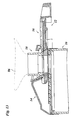
- Figure 1 shows, from the bottom to the top, an upper part of a toner reservoir 10 of, for example, a copier, a drawer 12 slidably disposed on top of the toner reservoir 10, a mounting structure 14, a slide 16 and a spout 18 of a refill container.
- a toner reservoir 10 of, for example, a copier
- drawer 12 slidably disposed on top of the toner reservoir 10
- mounting structure 14 a slide 16 and a spout 18 of a refill container.
- the toner reservoir 10 is tightly closed at the top end by a wall 20 which forms a circular refill opening 22 through toner powder may drop into the interior of the toner reservoir.
- the top surface of the wall 20 has to parallel ribs 24 formed symmetrically on both sides of the refill opening 22.
- a cushion 26 of elastomeric material is secured on the top surface of the wall 20 and fills the space between the two ribs 24.
- the cushion 26 is covered by a plastic film 28 which provides the cushion with a smooth surface finish.
- the surface of the film 28 is slightly elevated in comparison to the ribs 24.
- the cushion 26 and the film 28 are formed with a through-hole 30 which is concentric with the refill opening 22 but has a slightly smaller diameter.
- the drawer 12 has a handle 32 and a plate 34 which is slidingly supported on the flat top surface of the film 28.
- the plate 34 has a through-hole 36 which, in the position shown in figure 1, is offset from the refill opening 22, so that the refill opening is closed by the plate 34.
- the through-hole 36 may be made to coincide with the refill opening 22.
- the plate 34 has raised lateral walls 38 the top edges of which form inwardly projecting guide rails 40 and outwardly projecting stops 42.
- the portion of the plate 34 between the through-hole 36 and the handle 32 forms an upwardly open recess 44 (figure 1) which has a rounded and inclined rear wall 46 and a notch 48 extending along that wall.
- the mounting structure 14 accommodates the plate 34 of the drawer 12 in the position shown in figure 4 and can firmly be secured to the toner reservoir 10 with fastening means which have not been shown in the drawing for simplicity.
- a top wall 50 of the mounting structure has a curved and inclined portion 52 which, together with a bridge 54 bridging the plate 34, defines and upwardly flaring mounting socket 56 which is open at the bottom side towards the recess 44 of the drawer 12.
- the lower edge of the inclined wall portion 52 is formed with recesses 58 on either side. These recesses are engaged by the guide rails 40 of the drawer 12, so that the drawer is guided by the mounting structure 14 when it is drawn out. The outward movement of the drawer is limited by the stops 42 which cooperate with stops 60 of the mounting structure (figure 1).
- the slide 16 has a flat bottom 62 with a convexly curved rear edge 64, a front wall 66 and lateral walls 68. Adjacent to the rounded edge 64 the bottom 62 forms a cam 70 which mates with the notch 48 in the bottom of the recess 44 of the drawer 12.
- forwardly projecting abutments 72 of the slide engage the front wall 74 of the recess 44 below the bridge 54 of the mounting structure 14.
- the top surface of the bottom 62 is entirely covered by a thin semi-rigid foil 76 made of a plastic material such as Melinex.
- the foil 66 has a projecting portion 78 which projects beyond the rounded edge 64. When the slide is inserted in recess 44, the projecting portion 78 of the foil overlaps the part of the plate 34 defining the rear edge of the recess 44 and rests flat on the surface of the plate 34.
- the spout 18 shown in figures 1, 9 and 10 comprises a cylindrical tube 80 with a stepped bore 82 which defines a spout hole 84 and may be screwed onto or otherwise tightly secured to the neck of a bottle-shaped refill container 86 shown in phantom lines in figures 11 and 12.
- the tube 80 is surrounded by a downwardly tapered collar 88 which mates with the mounting socket 56 formed in the mounting structure 14.
- the collar 88 has flat side walls 90 formed with grooves 92. These grooves 92 serve for guiding inwardly projecting tongues 94 provided on the side wall 68 of the slide 16. In this way, the slide 16 is slidably mounted to the lower end of the spout 18.
- the bottom surface of the spout 18 is provided with an elastomeric sealing pad 96 which surrounds the spout opening 84 and resiliently engages the top surface of the foil 76, so that the spout opening 84 is tightly closed by the foil 76.
- the component parts of the refill mechanism described above are shown in the assembled state.
- the spout 18 and the slide 16 form part of the refill container 86 as supplied by the manufacturer.
- the edge of the projecting portion 78 of the foil 76 is flush with the curved outer collar 88 of the spout, so that the foil is protected against defection or damage.
- the refill container 86 is placed upside down onto the mounting structure 14, and the abutments 72 of the slide 16 are inserted underneath the bridge 54 and placed against the front wall 74 of the recess 44 in the drawer 12.
- the inclination of the walls 52 and 46 permits to smoothly accommodate the spout 18 and the slide 16 in the mouning socked 56 and the recess 44, resectively, by tilting the refill container 86 into the upright position.
- the cam 70 of the slide is thereby engaged into the notch 48 of the drawer.
- the projecting portion 78 of the foil 76 then rests on the top surface of the plate 34 and covers the gap formed between the rear edge 64 of the slide 16 and the wall 46 of the recess 44.
- the resilient sealing pad 96 slightly expands when it rides over the step 98 formed at the trailing edge of the foil 76 and then wipes over the top surface of the plate 34, so that the toner powder is wiped into the through-hole 36 of the drawer and then drops into the toner reservoir.
- the sweeping action of the sealing pad 96 at the step 98 is improved by the fact that, due to the curvature of the edge of the foil, this edge forms an acute angle with the direction of movement of the pad relative to the foil.
- Figure 13 shows the refill mechanism in the fully open state, in which the through-hole 36 in the plate of the drawer 12 is fully adjusted with the spout opening 84 and the refill opening 22, so that the toner powder may drop into the toner reservoir.
- the drawer 12 is then pushed back into the position shown in figure 11, the slide 16 comes again into engagement with the spout 18, and the projecting part 78 of the foil which then forms the leading edge scrapes over the sealing pad 96 so as to remove any toner powder adhering thereto.
- This toner will then be wiped into the through-hole 36 when the drawer is opened next time.
- the amount of toner powder accumulating behind the step 98 will always be limited, and no substantial toner will enter into the horizontal gap between the lower surface of the sealing pad 96 and the top surface of the slide 16.
- the sealing pad 96 may have a smooth finish at the lower surface, so that no grains of elastomeric material are rubbed-off by the projecting portion 78 of the foil 76.
- the film 28 on the cushion 26 supporting the plate 34 prevents disintegration of the cushion 26.
- the lower surface of the plate 34 of the drawer is formed with two annular embossments 100 and 102, as is shown in figures 1 and 4.
- the embossment 100 surrounds the through-hole 36 in the plate 34, whereas the embossment 102 surrounds the through-hole 30 of the cushion 26 when the drawer is in the closed position.
- a relatively firm engagement of the resiliently supported film 28 with the embossments 100 and 102 assures that any possible toner deposited on the top surface of the foil 28 will be swept into the through-hole 30.
- the plate 34 should be exactly flat or slightly convex, i.e. upwardly bulging, rather than concave, so that the portions of the embossments 100 and 102 which are most firmly pressed against the cushion 26 are the rear portion of the embossment 100 and the front portion of the embossment 102 as viewed in the direction in which the drawer is drawn out.
- top surface of the film 28 is absolutely flat and the drawer 12 is guided only in the mounting structure 14. This has the advantage that toner powder deposited on the film 28 will not enter between the mating surfaces of the guide structures which guide the drawer 12.
- the component parts of the refill mechanism, especially the drawer 12, should be made of a material which has a low adhesiveness for the toner powder.
- POM is a suitable material.
Abstract
Refill mechanism for filling toner powder from a refill container (86) into a toner reservoir
(10) of a copier or printer, comprising:
- a refill opening formed in the top of the toner reservoir (10);
- a drawer (12) slideable between an open position and a closed position for opening and closing the refill opening;
- a spout (18) formed on the refill container (86) and closed by a slide (16); and
- a mounting structure (14) for mounting the spout (18) on the toner reservoir (10) in a position above the refill opening, such that the slide (16) is engaged in a recess of the drawer (12) and, when the drawer is moved into the open position, is moved together with the drawer for opening the spout (16), so that the toner powder drops into the toner reservoir,
Description
- The invention relates to a refill mechanism for filling toner powder from a refill container into a toner reservoir of a copier or printer, comprising:
- a refill opening formed in the top of the toner reservoir;
- a drawer slideable between an open position and a closed position for opening and closing the refill opening;
- a spout formed on the refill container and closed by a slide; and
- a mounting structure for mounting the spout on the toner reservoir in a position above the refill opening, such that the slide is engaged in a recess of the drawer and, when the drawer is moved into the open position, is moved together with the drawer for opening the spout, so that the toner powder drops into the toner reservoir.
- A copier, a printer or any other machine which an image is developed with toner powder comprises a toner reservoir which accommodates a supply of fine toner powder which is gradually consumed in the course of image development. From time to time, the toner reservoir needs to be refilled with toner powder from a refill container, e.g. a bottle, a refill cartridge or the like. Since the toner powder typically consists of very fine toner particles, even a slight air draft is sufficient for swirling up a dust of toner particles, when the toner powder is exposed to the open air. Since the toner is strongly pigmented, this dust is likely to stain the environment. For this reason, the refill mechanism described above is designed so as to prevent the toner powder from being exposed to the open air even in the refill process, so that no toner dust will be generated and the user who refills the toner reservoir is protected against coming into direct contact with the toner powder.
- When the drawer is opened, the lower surface of the spout wipes over the top surpace of the drawer, and the toner powder is swept into the refill opening. It turns out however that, in the course of frequent refill processes occurring during the lifetime of the copier, a certain amount of toner powder may accumulate on the top surface of the drawer. As a result, slight amounts of toner powder may escape into the environment and may stain the fingers and clothes of the user. More importantly, when the drawer and the slide which are both in sliding contact with the lower surface of the spout are moved back and forth between the open and closed positions, toner powder may be entrained into the gap between the sliding surfaces and, due to frictional heat, will be sintered or baked together to form coating layers on the sliding surfaces. These coating layers are eventually peeled-off, so that flakes of sintered toner material are likely to drop into the toner reservoir and to disturb the developing process, so that the quality of the developed images is impaired.
- In order to reduce this effect, resilient sealing pads may be employed which are relatively tightly pressed against the sliding surfaces of the slide and the drawer so as to prevent the toner powder from being deposited on these surfaces. This, however, leads to an increased frictional resistance and may make it difficult to manually operate the drawer and the slide.
- It is accordingly an object of the invention to provide a refill mechanism of the type indicated above which is easy to operate and nevertheless avoids the formation of toner flakes which may drop into the toner reservoir.
- According to the invention, this object is achieved by the feature that the top surface of the slide is covered by a foil which projects over the trailing edge of the slide, as viewed in the direction of the opening movement, and overlaps the adjacent edge of the recess of the drawer.
- Since the slide and the drawer are both in sliding engagement with the lower surface of the spout and the slide is further engaged in the recess of the drawer, there exists not only a horizontal gap between the lower surface of the spout and the top surfaces of the slide and the drawer, but also a vertical gap between the slide and the wall of the recess at the trailing edge of the slide. In the prior art arrangement, the vertical gap upwardly opens into the horizontal gap, so that T-shaped gap configuration is obtained. When the drawer is opened, the open vertical gap moves across the open cross-section of the spout and becomes filled with toner powder. Even when a resilient sealing pad is provided at the lower surface of the spout surrounding the opening cross section, so as to wipe off the toner powder from the top surfaces of the slide and the drawer, the toner powder accumulated in the vertical gap cannot be removed. This toner powder is therefore entrained into a region where the horizontal gap exists between the slide and the drawer on the one hand and the sealing pad of the spout on the other hand. Here, the toner powder is supported by the walls of the vertical gap which move relative to the sealing pad, and friction between the toner powder and the sealing paid will cause the toner powder to enter into the horizontal gap and to form sintered flakes.
- The invention is based on the observation that this effect is the main reason for the occurrence of toner flakes. Therefore, according to the invention, the vertical gap is covered by the projecting part of the foil, so that no toner powder may enter into the vertical gap.
- Since the projecting part of the foil overlaps the adjacent edge of the drawer, a minor step is formed between the top surface of the foil and the top surface of the drawer adjacent thereto. When the drawer is opened, the sealing pad of the spout rides over this step, and the toner powder can successfully be wiped off from the surface of the foil and the surface of the drawer in the descending direction of the step. As a result, only minor remnants of toner powder will remain right in front of the step. When the drawer is closed again, the step formed by the foil prevents these remnants of toner from coming into frictional contact with the sealing pad of the spout. Since an increased pressing force exists between the sealing pad and the edge of the foil which forms the step, the toner powder is efficiently prevented from entering into the gap between the top surface of the foil and the sealing pad. In addition, if toner powder adheres to the lower surface of the sealing pad, this toner powder will be scraped off by the edge of the foil which forms the leading edge when the drawer is closed. As a result, the entry of toner powder into the horizontal gap and the formation of toner flakes is successfully prevented. More specific features of the invention and their advantages will become evident from the dependent claims and from the description of a preferred embodiment of the invention given hereinbelow in conjunction with the drawings, in which:
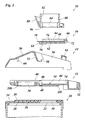
- Fig. 1
- is an exploded longitudinal section of the component parts of a refill mechanism according to the invention;
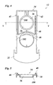
- Fig. 2
- is top plan view of a toner reservoir;
- Fig. 3
- is a cross-section taken along the line III-III in figure 2;
- Fig. 4
- is a bottom view of a drawer closing the toner reservoir;
- Fig. 5
- is a cross-section taken along the line V-V in figure 4;
- Fig. 6
- is a top plan view of a mounting structure for a refill container;
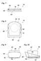
- Fig. 7
- is a rear view of a slide for opening and closing a spout of the refill container;
- Fig. 8
- is a top plan view of the slide shown in figure 7;
- Fig. 9
- is a rear view of the spout;
- Fig. 10
- is a lateral view of the spout;
- Fig. 11
- is a longitudinal section of the refill mechanism in the assembled and closed state; and
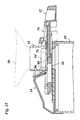
- Fig. 12
- is a longitudinal section of the refill mechanism in an intermediate position; and
- Fig. 13
- is a longitudinal section of the refill mechanism in the open state.
- Figure 1 shows, from the bottom to the top, an upper part of a
toner reservoir 10 of, for example, a copier, adrawer 12 slidably disposed on top of thetoner reservoir 10, amounting structure 14, aslide 16 and aspout 18 of a refill container. - As is shown in figures 1, 2 and 3, the
toner reservoir 10 is tightly closed at the top end by awall 20 which forms a circular refill opening 22 through toner powder may drop into the interior of the toner reservoir. The top surface of thewall 20 has toparallel ribs 24 formed symmetrically on both sides of the refill opening 22. Acushion 26 of elastomeric material is secured on the top surface of thewall 20 and fills the space between the tworibs 24. Thecushion 26 is covered by aplastic film 28 which provides the cushion with a smooth surface finish. The surface of thefilm 28 is slightly elevated in comparison to theribs 24. Thecushion 26 and thefilm 28 are formed with a through-hole 30 which is concentric with the refill opening 22 but has a slightly smaller diameter. - The
drawer 12 has ahandle 32 and aplate 34 which is slidingly supported on the flat top surface of thefilm 28. Theplate 34 has a through-hole 36 which, in the position shown in figure 1, is offset from therefill opening 22, so that the refill opening is closed by theplate 34. When thedrawer 12 is drawn-out to the right side in figure 1, the through-hole 36 may be made to coincide with therefill opening 22. - As can be seen in figures 4 and 5, the
plate 34 has raisedlateral walls 38 the top edges of which form inwardly projectingguide rails 40 and outwardly projecting stops 42. - The portion of the
plate 34 between the through-hole 36 and thehandle 32 forms an upwardly open recess 44 (figure 1) which has a rounded and inclinedrear wall 46 and anotch 48 extending along that wall. - The mounting
structure 14 accommodates theplate 34 of thedrawer 12 in the position shown in figure 4 and can firmly be secured to thetoner reservoir 10 with fastening means which have not been shown in the drawing for simplicity. Atop wall 50 of the mounting structure has a curved andinclined portion 52 which, together with abridge 54 bridging theplate 34, defines and upwardlyflaring mounting socket 56 which is open at the bottom side towards therecess 44 of thedrawer 12. As is shown in figures 1 and 6, the lower edge of theinclined wall portion 52 is formed withrecesses 58 on either side. These recesses are engaged by the guide rails 40 of thedrawer 12, so that the drawer is guided by the mountingstructure 14 when it is drawn out. The outward movement of the drawer is limited by thestops 42 which cooperate withstops 60 of the mounting structure (figure 1). - As is shown in figures 1, 7 and 8, the
slide 16 has a flat bottom 62 with a convexly curvedrear edge 64, afront wall 66 andlateral walls 68. Adjacent to therounded edge 64 the bottom 62 forms acam 70 which mates with thenotch 48 in the bottom of therecess 44 of thedrawer 12. When theslide 16 is inserted into therecess 44, forwardly projectingabutments 72 of the slide engage thefront wall 74 of therecess 44 below thebridge 54 of the mountingstructure 14.
The top surface of the bottom 62 is entirely covered by a thinsemi-rigid foil 76 made of a plastic material such as Melinex. Thefoil 66 has a projectingportion 78 which projects beyond therounded edge 64. When the slide is inserted inrecess 44, the projectingportion 78 of the foil overlaps the part of theplate 34 defining the rear edge of therecess 44 and rests flat on the surface of theplate 34. - The
spout 18 shown in figures 1, 9 and 10 comprises acylindrical tube 80 with a stepped bore 82 which defines aspout hole 84 and may be screwed onto or otherwise tightly secured to the neck of a bottle-shapedrefill container 86 shown in phantom lines in figures 11 and 12. Thetube 80 is surrounded by a downwardly taperedcollar 88 which mates with the mountingsocket 56 formed in the mountingstructure 14. As can be seen in figures 9 and 10, thecollar 88 hasflat side walls 90 formed withgrooves 92. Thesegrooves 92 serve for guiding inwardly projectingtongues 94 provided on theside wall 68 of theslide 16. In this way, theslide 16 is slidably mounted to the lower end of thespout 18. - The bottom surface of the
spout 18 is provided with anelastomeric sealing pad 96 which surrounds thespout opening 84 and resiliently engages the top surface of thefoil 76, so that thespout opening 84 is tightly closed by thefoil 76. - In figure 11, the component parts of the refill mechanism described above are shown in the assembled state. The
spout 18 and theslide 16 form part of therefill container 86 as supplied by the manufacturer. The edge of the projectingportion 78 of thefoil 76 is flush with the curvedouter collar 88 of the spout, so that the foil is protected against defection or damage. When thetoner reservoir 10 needs to be refilled, therefill container 86 is placed upside down onto the mountingstructure 14, and theabutments 72 of theslide 16 are inserted underneath thebridge 54 and placed against thefront wall 74 of therecess 44 in thedrawer 12. The inclination of thewalls spout 18 and theslide 16 in the mouning socked 56 and therecess 44, resectively, by tilting therefill container 86 into the upright position. Thecam 70 of the slide is thereby engaged into thenotch 48 of the drawer. The projectingportion 78 of thefoil 76 then rests on the top surface of theplate 34 and covers the gap formed between therear edge 64 of theslide 16 and thewall 46 of therecess 44. - When the
drawer 12 is drawn out, as is shown in figure 12, thesilde 16 is entrained by the drawer, whereas thespout 18 is held in position by thebridge 54 of the mounting structure. The rear edge of theslide 16, which is then the trailing edge, moves across thespout opening 84. The toner powder accommodated in therefill container 86 rests on thefoil 76 and is kept within the cross section of thespout opening 84, because thesealing pad 96 wipes over the surface of thefoil 76. Since the projectingportion 78 of the foil covers the gap between the trailing edge of theslide 16 and therecess 44, no toner powder will enter into this gap. As is further shown in figure 12, theresilient sealing pad 96 slightly expands when it rides over thestep 98 formed at the trailing edge of thefoil 76 and then wipes over the top surface of theplate 34, so that the toner powder is wiped into the through-hole 36 of the drawer and then drops into the toner reservoir. The sweeping action of thesealing pad 96 at thestep 98 is improved by the fact that, due to the curvature of the edge of the foil, this edge forms an acute angle with the direction of movement of the pad relative to the foil. - Figure 13 shows the refill mechanism in the fully open state, in which the through-
hole 36 in the plate of thedrawer 12 is fully adjusted with thespout opening 84 and therefill opening 22, so that the toner powder may drop into the toner reservoir. When thedrawer 12 is then pushed back into the position shown in figure 11, theslide 16 comes again into engagement with thespout 18, and the projectingpart 78 of the foil which then forms the leading edge scrapes over thesealing pad 96 so as to remove any toner powder adhering thereto. This toner will then be wiped into the through-hole 36 when the drawer is opened next time. Thus, the amount of toner powder accumulating behind thestep 98 will always be limited, and no substantial toner will enter into the horizontal gap between the lower surface of thesealing pad 96 and the top surface of theslide 16. - It will be understood that the
sealing pad 96 may have a smooth finish at the lower surface, so that no grains of elastomeric material are rubbed-off by the projectingportion 78 of thefoil 76. Similarly, thefilm 28 on thecushion 26 supporting theplate 34 prevents disintegration of thecushion 26. Thus, it is assured that the quality of the toner in the toner reservoir will not be deteriorated by grains of elastomeric sealing material. - In order to reduce the amount of friction between the
drawer 12 and thefilm 28 of thecushion 26 and in order to closely seal the top edge of the through-hole 30 of thecushion 26, the lower surface of theplate 34 of the drawer is formed with twoannular embossments embossment 100 surrounds the through-hole 36 in theplate 34, whereas theembossment 102 surrounds the through-hole 30 of thecushion 26 when the drawer is in the closed position. A relatively firm engagement of the resiliently supportedfilm 28 with theembossments foil 28 will be swept into the through-hole 30. In order to achieve this effect with high reliability, theplate 34 should be exactly flat or slightly convex, i.e. upwardly bulging, rather than concave, so that the portions of theembossments cushion 26 are the rear portion of theembossment 100 and the front portion of theembossment 102 as viewed in the direction in which the drawer is drawn out. - When the
embossment 102 slides over the edges of thecushion 26 defining the through-hole 30, these edges may slightly be deflected downwardly, because therefill opening 22 has a somewhat larger diameter. This also helps to avoid damage to theelastomeric cushion 26. - It will further be observed that the top surface of the
film 28 is absolutely flat and thedrawer 12 is guided only in the mountingstructure 14. This has the advantage that toner powder deposited on thefilm 28 will not enter between the mating surfaces of the guide structures which guide thedrawer 12. - The component parts of the refill mechanism, especially the
drawer 12, should be made of a material which has a low adhesiveness for the toner powder. For example, POM is a suitable material.
Claims (9)
- Refill mechanism for filling toner powder from a refill container (86) into a toner reservoir (10) of a copier or printer, comprising:characterized in that the top surface of the slide (16) is covered by a foil (76) which projects over the trailing edge (64) of the slide, as viewed in the direction of the opening movement, and overlaps the adjacent edge of the recess (44) of the drawer (12).a refill opening (22) formed in the top of the toner reservoir (10);a drawer (12) slideable between an open position and a closed position for opening and closing the refill opening (22);a spout (18) formed on the refill container (86) and closed by a slide (16); anda mounting structure (14) for mounting the spout (18) on the toner reservoir (10) in a position above the refill opening (22), such that the slide (16) is engaged in a recess (44) of the drawer (12) and, when the drawer is moved into the open position, is moved together with the drawer for opening the spout (16), so that the toner powder drops into the toner reservoir,
- Refill mechanism as defined in claim 1, wherein the projecting part (78) of the foil (76) rests flat on the top surface of the drawer (12) when the slide (16) is accommodated in the recess (44).
- Refill mechanism as defined in claim 2, wherein the trailing edge (64) of the slide (16) and the corresponding edge of the foil (76) have a convex curvature.
- Refill mechanism as defined in any of the preceding claims, wherein the foil (76) is made of a semi-rigid material and the spout (18) has an outer collar (88) the lower edge of which is flush with the edge of the projecting part (78) of the foil (76) when the drawer (16) is in the fully closed position relative to the spout (18).
- Refill mechanism as defined in any of the preceding claims, wherein the lower surface of the spout (18) held in engagement with the top surface of the foil (76) is formed by an elastic sealing pad (96) surrounding the spout opening (84).
- Refill mechanism as defined in any of the preceding claims, wherein the drawer (12) is slidingly supported on a flat top surface of the toner reservoir (10) and is slidably guided in the mounting structure (14).
- Refill mechanism as defined in any of the preceding claims, wherein the drawer (12) has a through-hole (36) which is aligned with the refill opening (22) when the drawer is in the open position, and the lower surface of the drawer (12) has two circular embossments (100, 102) one (100) of which surrounds the through-hole (36), whereas the other one (102) surrounds the refill opening (22) when the drawer is in the closed position.
- Refill mechanism as defined in any of the preceding claims, wherein the top surface of the toner reservoir (10) is formed by a film (28) covering a cushion (26) which is made of an elastomeric material and has a through-hole (30) concentric with the refill opening (22).
- Refill mechanism as defined in claim 8, wherein the diameter of the through-hole (30) in the cushion (26) is smaller than the diameter of the refill opening (22).
Priority Applications (4)
| Application Number | Priority Date | Filing Date | Title |
|---|---|---|---|
| EP00202625A EP1176477A1 (en) | 2000-07-24 | 2000-07-24 | Refill mechanism for toner powder |
| JP2001210320A JP4794077B2 (en) | 2000-07-24 | 2001-07-11 | Toner powder replenishment mechanism |
| EP01202681.1A EP1179755B1 (en) | 2000-07-24 | 2001-07-12 | Refill mechanism for toner powder |
| US09/910,728 US6463243B1 (en) | 2000-07-24 | 2001-07-24 | Refill mechanism for toner powder |
Applications Claiming Priority (1)
| Application Number | Priority Date | Filing Date | Title |
|---|---|---|---|
| EP00202625A EP1176477A1 (en) | 2000-07-24 | 2000-07-24 | Refill mechanism for toner powder |
Publications (1)
| Publication Number | Publication Date |
|---|---|
| EP1176477A1 true EP1176477A1 (en) | 2002-01-30 |
Family
ID=8171845
Family Applications (1)
| Application Number | Title | Priority Date | Filing Date |
|---|---|---|---|
| EP00202625A Withdrawn EP1176477A1 (en) | 2000-07-24 | 2000-07-24 | Refill mechanism for toner powder |
Country Status (3)
| Country | Link |
|---|---|
| US (1) | US6463243B1 (en) |
| EP (1) | EP1176477A1 (en) |
| JP (1) | JP4794077B2 (en) |
Cited By (1)
| Publication number | Priority date | Publication date | Assignee | Title |
|---|---|---|---|---|
| DE102006007304B3 (en) * | 2006-02-16 | 2007-09-13 | OCé PRINTING SYSTEMS GMBH | Arrangement for conveying toner from a toner reservoir into a toner receiving container, in particular in a printing or copying device |
Families Citing this family (6)
| Publication number | Priority date | Publication date | Assignee | Title |
|---|---|---|---|---|
| KR100532123B1 (en) * | 2004-02-21 | 2005-11-29 | 삼성전자주식회사 | Developing apparatus and electrophotographic image forming apparatus therewith |
| JP4651011B2 (en) * | 2005-04-28 | 2011-03-16 | 株式会社リコー | Developing device, process cartridge, and image forming apparatus |
| JP4560443B2 (en) * | 2005-05-24 | 2010-10-13 | 株式会社リコー | Developing device and image forming apparatus |
| WO2013057006A1 (en) | 2011-10-19 | 2013-04-25 | Oce-Technologies B.V. | Toner refill device |
| EP3749589A1 (en) * | 2018-02-05 | 2020-12-16 | Ecolab USA, Inc. | Packaging and docking system for non-contact chemical dispensing |
| US11401084B2 (en) | 2019-02-05 | 2022-08-02 | Ecolab Usa Inc. | Packaging and docking system for non-contact chemical dispensing |
Citations (3)
| Publication number | Priority date | Publication date | Assignee | Title |
|---|---|---|---|---|
| US4834246A (en) * | 1987-03-31 | 1989-05-30 | Fuji Xerox Co., Ltd. | Toner cartridge |
| JPH04128855A (en) * | 1990-09-20 | 1992-04-30 | Canon Inc | Developer replenishing device |
| US5729794A (en) * | 1996-05-20 | 1998-03-17 | Eastman Kodak Company | Toner container having a web seal |
Family Cites Families (8)
| Publication number | Priority date | Publication date | Assignee | Title |
|---|---|---|---|---|
| DE3374352D1 (en) * | 1982-08-23 | 1987-12-10 | Konishiroku Photo Ind | Toner dispensing apparatus |
| US4937628A (en) * | 1989-04-07 | 1990-06-26 | Xerox Corporation | Apparatus for storing and dispensing particulate material |
| JP2565575B2 (en) * | 1989-12-08 | 1996-12-18 | 三田工業株式会社 | Toner cartridge |
| JPH0466983A (en) * | 1990-07-04 | 1992-03-03 | Mita Ind Co Ltd | Toner replenishing device |
| JPH04301868A (en) * | 1991-03-29 | 1992-10-26 | Canon Inc | Developer housing device |
| CA2068358C (en) * | 1991-05-14 | 1998-12-22 | Yoshihiko Yamada | Developer replenishing cartridge and developer receiving apparatus within which such cartridge is mounted |
| JP2802854B2 (en) * | 1992-04-14 | 1998-09-24 | シャープ株式会社 | Toner supply device and toner container |
| JP2810915B2 (en) * | 1992-07-29 | 1998-10-15 | 三田工業株式会社 | Toner cartridge |
-
2000
- 2000-07-24 EP EP00202625A patent/EP1176477A1/en not_active Withdrawn
-
2001
- 2001-07-11 JP JP2001210320A patent/JP4794077B2/en not_active Expired - Lifetime
- 2001-07-24 US US09/910,728 patent/US6463243B1/en not_active Expired - Lifetime
Patent Citations (3)
| Publication number | Priority date | Publication date | Assignee | Title |
|---|---|---|---|---|
| US4834246A (en) * | 1987-03-31 | 1989-05-30 | Fuji Xerox Co., Ltd. | Toner cartridge |
| JPH04128855A (en) * | 1990-09-20 | 1992-04-30 | Canon Inc | Developer replenishing device |
| US5729794A (en) * | 1996-05-20 | 1998-03-17 | Eastman Kodak Company | Toner container having a web seal |
Non-Patent Citations (1)
| Title |
|---|
| PATENT ABSTRACTS OF JAPAN vol. 016, no. 393 (P - 1406) 20 August 1992 (1992-08-20) * |
Cited By (2)
| Publication number | Priority date | Publication date | Assignee | Title |
|---|---|---|---|---|
| DE102006007304B3 (en) * | 2006-02-16 | 2007-09-13 | OCé PRINTING SYSTEMS GMBH | Arrangement for conveying toner from a toner reservoir into a toner receiving container, in particular in a printing or copying device |
| US8139986B2 (en) | 2006-02-16 | 2012-03-20 | Oce Printing Systems Gmbh | Arrangement for conveying toner from a toner supply container into a toner receiving container |
Also Published As
| Publication number | Publication date |
|---|---|
| JP4794077B2 (en) | 2011-10-12 |
| JP2002082519A (en) | 2002-03-22 |
| US6463243B1 (en) | 2002-10-08 |
| US20020025193A1 (en) | 2002-02-28 |
Similar Documents
| Publication | Publication Date | Title |
|---|---|---|
| US7536139B2 (en) | Powder container for use in an image forming apparatus having an opening which faces horizontally | |
| EP0843233B1 (en) | Toner supply cartridge and image forming apparatus | |
| US7840160B2 (en) | Toner cartridge with memory element, image drum unit with the toner cartridge, and image forming apparatus with the image drum unit | |
| RU2754832C2 (en) | Developer feed tank and developer feed system | |
| JP2007310148A (en) | Toner cartridge | |
| JPS5950985B2 (en) | toner container | |
| CN115480467A (en) | Developer supply container and developer supply system | |
| EP0892321B1 (en) | Toner container and toner supply apparatus | |
| US6363235B1 (en) | Toner bottle/cartridge housing attachment assembly | |
| EP1176477A1 (en) | Refill mechanism for toner powder | |
| US8811861B2 (en) | Developer container, image forming apparatus, and developer container controlling method | |
| TWI402637B (en) | Image forming agent storage device and image forming apparatus | |
| EP1434108B1 (en) | Image forming apparatus and mounting construction of a toner cartridge | |
| EP1179755B1 (en) | Refill mechanism for toner powder | |
| KR20110068791A (en) | Toner cartridge and image forming apparatus | |
| JPH0695505A (en) | Toner supply device | |
| JP4878499B2 (en) | Toner cartridge | |
| US5970292A (en) | Securing feature for toner container shutter | |
| EP0699972A2 (en) | Printer with toner loader door | |
| US5555080A (en) | Slide cover for marking particle cartridge | |
| CN214795579U (en) | Carbon powder cylinder | |
| JP3143495B2 (en) | Developer supply device and developer supply container | |
| JP4603859B2 (en) | Toner supply means and image forming apparatus | |
| US7085515B2 (en) | Developer cartridge including sealing gasket | |
| JPH0611964A (en) | Developer supplementing device and image forming device provided there with |
Legal Events
| Date | Code | Title | Description |
|---|---|---|---|
| PUAI | Public reference made under article 153(3) epc to a published international application that has entered the european phase |
Free format text: ORIGINAL CODE: 0009012 |
|
| AK | Designated contracting states |
Kind code of ref document: A1 Designated state(s): AT BE CH CY DE DK ES FI FR GB GR IE IT LI LU MC NL PT SE |
|
| AX | Request for extension of the european patent |
Free format text: AL;LT;LV;MK;RO;SI |
|
| STAA | Information on the status of an ep patent application or granted ep patent |
Free format text: STATUS: THE APPLICATION IS DEEMED TO BE WITHDRAWN |
|
| 18D | Application deemed to be withdrawn |
Effective date: 20011127 |