EP1179357B1 - Screen assembly, vibratory separator and method of screening - Google Patents
Screen assembly, vibratory separator and method of screening Download PDFInfo
- Publication number
- EP1179357B1 EP1179357B1 EP01204099A EP01204099A EP1179357B1 EP 1179357 B1 EP1179357 B1 EP 1179357B1 EP 01204099 A EP01204099 A EP 01204099A EP 01204099 A EP01204099 A EP 01204099A EP 1179357 B1 EP1179357 B1 EP 1179357B1
- Authority
- EP
- European Patent Office
- Prior art keywords
- screen
- ridge
- ridges
- screen assembly
- screening material
- Prior art date
- Legal status (The legal status is an assumption and is not a legal conclusion. Google has not performed a legal analysis and makes no representation as to the accuracy of the status listed.)
- Expired - Lifetime
Links
- 238000012216 screening Methods 0.000 title claims abstract description 40
- 238000000034 method Methods 0.000 title claims abstract description 9
- 239000000463 material Substances 0.000 claims abstract description 44
- 239000012530 fluid Substances 0.000 claims abstract description 14
- 239000002245 particle Substances 0.000 claims abstract description 13
- 239000007787 solid Substances 0.000 description 6
- 238000005553 drilling Methods 0.000 description 5
- 238000002788 crimping Methods 0.000 description 1
- 238000001914 filtration Methods 0.000 description 1
- 238000005259 measurement Methods 0.000 description 1
- 238000000926 separation method Methods 0.000 description 1
- 238000003466 welding Methods 0.000 description 1
Images


Classifications
-
- B—PERFORMING OPERATIONS; TRANSPORTING
- B07—SEPARATING SOLIDS FROM SOLIDS; SORTING
- B07B—SEPARATING SOLIDS FROM SOLIDS BY SIEVING, SCREENING, SIFTING OR BY USING GAS CURRENTS; SEPARATING BY OTHER DRY METHODS APPLICABLE TO BULK MATERIAL, e.g. LOOSE ARTICLES FIT TO BE HANDLED LIKE BULK MATERIAL
- B07B1/00—Sieving, screening, sifting, or sorting solid materials using networks, gratings, grids, or the like
- B07B1/46—Constructional details of screens in general; Cleaning or heating of screens
- B07B1/4609—Constructional details of screens in general; Cleaning or heating of screens constructional details of screening surfaces or meshes
- B07B1/4654—Corrugated Screening surfaces
-
- B—PERFORMING OPERATIONS; TRANSPORTING
- B01—PHYSICAL OR CHEMICAL PROCESSES OR APPARATUS IN GENERAL
- B01D—SEPARATION
- B01D29/00—Filters with filtering elements stationary during filtration, e.g. pressure or suction filters, not covered by groups B01D24/00 - B01D27/00; Filtering elements therefor
- B01D29/01—Filters with filtering elements stationary during filtration, e.g. pressure or suction filters, not covered by groups B01D24/00 - B01D27/00; Filtering elements therefor with flat filtering elements
- B01D29/012—Making filtering elements
-
- B—PERFORMING OPERATIONS; TRANSPORTING
- B01—PHYSICAL OR CHEMICAL PROCESSES OR APPARATUS IN GENERAL
- B01D—SEPARATION
- B01D29/00—Filters with filtering elements stationary during filtration, e.g. pressure or suction filters, not covered by groups B01D24/00 - B01D27/00; Filtering elements therefor
- B01D29/01—Filters with filtering elements stationary during filtration, e.g. pressure or suction filters, not covered by groups B01D24/00 - B01D27/00; Filtering elements therefor with flat filtering elements
- B01D29/05—Filters with filtering elements stationary during filtration, e.g. pressure or suction filters, not covered by groups B01D24/00 - B01D27/00; Filtering elements therefor with flat filtering elements supported
- B01D29/07—Filters with filtering elements stationary during filtration, e.g. pressure or suction filters, not covered by groups B01D24/00 - B01D27/00; Filtering elements therefor with flat filtering elements supported with corrugated, folded or wound filtering sheets
-
- B—PERFORMING OPERATIONS; TRANSPORTING
- B01—PHYSICAL OR CHEMICAL PROCESSES OR APPARATUS IN GENERAL
- B01D—SEPARATION
- B01D29/00—Filters with filtering elements stationary during filtration, e.g. pressure or suction filters, not covered by groups B01D24/00 - B01D27/00; Filtering elements therefor
- B01D29/44—Edge filtering elements, i.e. using contiguous impervious surfaces
- B01D29/445—Bar screens
-
- B—PERFORMING OPERATIONS; TRANSPORTING
- B01—PHYSICAL OR CHEMICAL PROCESSES OR APPARATUS IN GENERAL
- B01D—SEPARATION
- B01D33/00—Filters with filtering elements which move during the filtering operation
- B01D33/01—Filters with filtering elements which move during the filtering operation with translationally moving filtering elements, e.g. pistons
- B01D33/015—Filters with filtering elements which move during the filtering operation with translationally moving filtering elements, e.g. pistons with flat filtering elements
- B01D33/0183—Filters with filtering elements which move during the filtering operation with translationally moving filtering elements, e.g. pistons with flat filtering elements supported
-
- B—PERFORMING OPERATIONS; TRANSPORTING
- B01—PHYSICAL OR CHEMICAL PROCESSES OR APPARATUS IN GENERAL
- B01D—SEPARATION
- B01D33/00—Filters with filtering elements which move during the filtering operation
- B01D33/01—Filters with filtering elements which move during the filtering operation with translationally moving filtering elements, e.g. pistons
- B01D33/03—Filters with filtering elements which move during the filtering operation with translationally moving filtering elements, e.g. pistons with vibrating filter elements
- B01D33/0346—Filters with filtering elements which move during the filtering operation with translationally moving filtering elements, e.g. pistons with vibrating filter elements with flat filtering elements
- B01D33/0376—Filters with filtering elements which move during the filtering operation with translationally moving filtering elements, e.g. pistons with vibrating filter elements with flat filtering elements supported
- B01D33/0384—Filters with filtering elements which move during the filtering operation with translationally moving filtering elements, e.g. pistons with vibrating filter elements with flat filtering elements supported with corrugated, folded or wound filtering sheets
-
- B—PERFORMING OPERATIONS; TRANSPORTING
- B07—SEPARATING SOLIDS FROM SOLIDS; SORTING
- B07B—SEPARATING SOLIDS FROM SOLIDS BY SIEVING, SCREENING, SIFTING OR BY USING GAS CURRENTS; SEPARATING BY OTHER DRY METHODS APPLICABLE TO BULK MATERIAL, e.g. LOOSE ARTICLES FIT TO BE HANDLED LIKE BULK MATERIAL
- B07B1/00—Sieving, screening, sifting, or sorting solid materials using networks, gratings, grids, or the like
- B07B1/46—Constructional details of screens in general; Cleaning or heating of screens
- B07B1/4609—Constructional details of screens in general; Cleaning or heating of screens constructional details of screening surfaces or meshes
- B07B1/4618—Manufacturing of screening surfaces
-
- B—PERFORMING OPERATIONS; TRANSPORTING
- B07—SEPARATING SOLIDS FROM SOLIDS; SORTING
- B07B—SEPARATING SOLIDS FROM SOLIDS BY SIEVING, SCREENING, SIFTING OR BY USING GAS CURRENTS; SEPARATING BY OTHER DRY METHODS APPLICABLE TO BULK MATERIAL, e.g. LOOSE ARTICLES FIT TO BE HANDLED LIKE BULK MATERIAL
- B07B1/00—Sieving, screening, sifting, or sorting solid materials using networks, gratings, grids, or the like
- B07B1/46—Constructional details of screens in general; Cleaning or heating of screens
- B07B1/4609—Constructional details of screens in general; Cleaning or heating of screens constructional details of screening surfaces or meshes
- B07B1/4627—Repairing of screening surfaces
-
- B—PERFORMING OPERATIONS; TRANSPORTING
- B07—SEPARATING SOLIDS FROM SOLIDS; SORTING
- B07B—SEPARATING SOLIDS FROM SOLIDS BY SIEVING, SCREENING, SIFTING OR BY USING GAS CURRENTS; SEPARATING BY OTHER DRY METHODS APPLICABLE TO BULK MATERIAL, e.g. LOOSE ARTICLES FIT TO BE HANDLED LIKE BULK MATERIAL
- B07B1/00—Sieving, screening, sifting, or sorting solid materials using networks, gratings, grids, or the like
- B07B1/46—Constructional details of screens in general; Cleaning or heating of screens
- B07B1/4609—Constructional details of screens in general; Cleaning or heating of screens constructional details of screening surfaces or meshes
- B07B1/4645—Screening surfaces built up of modular elements
-
- B—PERFORMING OPERATIONS; TRANSPORTING
- B07—SEPARATING SOLIDS FROM SOLIDS; SORTING
- B07B—SEPARATING SOLIDS FROM SOLIDS BY SIEVING, SCREENING, SIFTING OR BY USING GAS CURRENTS; SEPARATING BY OTHER DRY METHODS APPLICABLE TO BULK MATERIAL, e.g. LOOSE ARTICLES FIT TO BE HANDLED LIKE BULK MATERIAL
- B07B1/00—Sieving, screening, sifting, or sorting solid materials using networks, gratings, grids, or the like
- B07B1/46—Constructional details of screens in general; Cleaning or heating of screens
- B07B1/4609—Constructional details of screens in general; Cleaning or heating of screens constructional details of screening surfaces or meshes
- B07B1/4663—Multi-layer screening surfaces
-
- B—PERFORMING OPERATIONS; TRANSPORTING
- B07—SEPARATING SOLIDS FROM SOLIDS; SORTING
- B07B—SEPARATING SOLIDS FROM SOLIDS BY SIEVING, SCREENING, SIFTING OR BY USING GAS CURRENTS; SEPARATING BY OTHER DRY METHODS APPLICABLE TO BULK MATERIAL, e.g. LOOSE ARTICLES FIT TO BE HANDLED LIKE BULK MATERIAL
- B07B1/00—Sieving, screening, sifting, or sorting solid materials using networks, gratings, grids, or the like
- B07B1/46—Constructional details of screens in general; Cleaning or heating of screens
- B07B1/4609—Constructional details of screens in general; Cleaning or heating of screens constructional details of screening surfaces or meshes
- B07B1/4672—Woven meshes
-
- B—PERFORMING OPERATIONS; TRANSPORTING
- B07—SEPARATING SOLIDS FROM SOLIDS; SORTING
- B07B—SEPARATING SOLIDS FROM SOLIDS BY SIEVING, SCREENING, SIFTING OR BY USING GAS CURRENTS; SEPARATING BY OTHER DRY METHODS APPLICABLE TO BULK MATERIAL, e.g. LOOSE ARTICLES FIT TO BE HANDLED LIKE BULK MATERIAL
- B07B1/00—Sieving, screening, sifting, or sorting solid materials using networks, gratings, grids, or the like
- B07B1/46—Constructional details of screens in general; Cleaning or heating of screens
- B07B1/4609—Constructional details of screens in general; Cleaning or heating of screens constructional details of screening surfaces or meshes
- B07B1/469—Perforated sheet-like material
-
- B—PERFORMING OPERATIONS; TRANSPORTING
- B07—SEPARATING SOLIDS FROM SOLIDS; SORTING
- B07B—SEPARATING SOLIDS FROM SOLIDS BY SIEVING, SCREENING, SIFTING OR BY USING GAS CURRENTS; SEPARATING BY OTHER DRY METHODS APPLICABLE TO BULK MATERIAL, e.g. LOOSE ARTICLES FIT TO BE HANDLED LIKE BULK MATERIAL
- B07B1/00—Sieving, screening, sifting, or sorting solid materials using networks, gratings, grids, or the like
- B07B1/46—Constructional details of screens in general; Cleaning or heating of screens
- B07B1/48—Stretching devices for screens
-
- E—FIXED CONSTRUCTIONS
- E21—EARTH DRILLING; MINING
- E21B—EARTH DRILLING, e.g. DEEP DRILLING; OBTAINING OIL, GAS, WATER, SOLUBLE OR MELTABLE MATERIALS OR A SLURRY OF MINERALS FROM WELLS
- E21B21/00—Methods or apparatus for flushing boreholes, e.g. by use of exhaust air from motor
- E21B21/06—Arrangements for treating drilling fluids outside the borehole
- E21B21/063—Arrangements for treating drilling fluids outside the borehole by separating components
- E21B21/065—Separating solids from drilling fluids
-
- B—PERFORMING OPERATIONS; TRANSPORTING
- B07—SEPARATING SOLIDS FROM SOLIDS; SORTING
- B07B—SEPARATING SOLIDS FROM SOLIDS BY SIEVING, SCREENING, SIFTING OR BY USING GAS CURRENTS; SEPARATING BY OTHER DRY METHODS APPLICABLE TO BULK MATERIAL, e.g. LOOSE ARTICLES FIT TO BE HANDLED LIKE BULK MATERIAL
- B07B2201/00—Details applicable to machines for screening using sieves or gratings
- B07B2201/04—Multiple deck screening devices comprising one or more superimposed screens
Definitions
- the present invention relates to a screen assembly, a vibratory separator and a method of screening.
- drilling fluid When drilling a wellbore in the earth's surface, drilling fluid is used to maintain the tip of a drill cool and to carry solids to the surface of the wellbore. Once at the surface the solids are removed from the drilling fluid which can then be re-used.
- Types of apparatus that can remove solids from drilling fluid include a vibratory separator known as shale shaker.
- a typical shale shaker is disclosed in WO-A-96/33792.
- the wire mesh is very fine and does not have a high durability. It is advantageous to have a screen which has high durability.
- Shale shakers are limited in size, especially those used on offshore platforms where space is at a premium. Accordingly, it is advantageous to filter a large quantity of particle laden mud using standard size shale shakers.
- a screen assembly for a vibratory separator comprising a ridge-valley series of screening material having a plurality of alternating ridges and valleys and two spaced apart ends having ridge openings below the ridges, said openings covered with screen or mesh material characterised in that said openings are covered with screen or mesh material in a generally bulbous shape.
- the screen assembly further comprises a hook strip connection on spaced-apart sides of said ridge-valley series of screening material.
- the ridges are of at least two different sizes.
- the ridges are of at least two different widths.
- the ridges are of a least two different heights.
- the screen assembly comprises two side portions and a central portion, wherein said ridges decrease in size from said side portions towards said central portion.
- the ridges decrease in height.
- the screening material further comprises at least a second layer of screening material.
- the screen assembly comprises a second screen, wherein the ridges of said second screen are in line with the ridges of said first screen.
- the screen assembly further comprises a flat screen of screening material, said ridge-valley series on said flat screen.
- the flat screen is made of coarse mesh and said ridge-valley series are made of fine mesh.
- the first aspect of the present invention also provides a vibratory separator comprising a screen assembly of the present invention, the screen assembly comprising a ridge-valley series of screening material having a plurality of alternating ridges and valleys and two spaced apart ends having ridge openings below the ridges, said openings covered with screen or mesh material characterised in that said ends are covered with screen or mesh material in a generally bulbous shape.
- the first aspect of the present invention further provides a method for screening using the vibratory separator of the invention said method comprising the step of vibrating said ridge-valley series of screening material, pouring a particle laden fluid on to one of said ridge-valley series of screening material thereon, allowing fluid and predetermined size particles therethrough, and vibrating particles larger than said predetermined size to a far end of one other of said ridge-valley series of screening material.
- Figure 1A to 1D show a screen assembly generally identified by reference numeral 1 for use in, for example, a vibratory shaker such as a shale shaker.
- the present patent is derived from the earlier EP-A-1.163.037 (parent European Patent Application No. 00 915 179.6) derived from WO-A-00/64558 discloses a screen assembly for a vibratory separator, the screen assembly comprising at least a first and second ridge-valley series of screening material comprising a plurality of alternating ridges and valleys of screening material, each ridge having a ridge end, characterised in that at least the ridge ends of adjacent sides of said first and second ridge-valley series of screening material are offset or overlap when viewed from one end.
- the screen assembly 1 has hook strips 2 and 4 on either side thereof. Screening material 6 is connected along the length of each hook strip by known methods, for example folding, welding, crimping together, epoxying, press/fiction fit, and/or interlocking of parts. In one aspect no underlying plate, straps, or strips and no frame are used with the screen assembly 1.
- the screening material 6 may be any known screening material, screen and/or mesh or combination thereof and/or any screening material disclosed herein.
- the screening material 6 includes a lower mesh (for example 1 to 80 mesh) 8 which may be a relatively coarse mesh and an upper mesh 10 (for example 8 to 400 mesh) and which may be a relatively fine mesh.
- Two fine mesh screens and one coarse mesh screen may also be used. The fine mesh may be bonded to the coarse mesh, sewed to the coarse mesh, glued to it, welded to it, and/or sintered to it.
- One, two, three or more layers of wire mesh may be used instead of or with such a plate, straps, or strips.
- a flat coarse mesh (for example mesh 1 to mesh 12) is used instead of or in addition to a plate, straps, or strips.
- Mesh (fine, coarse, or both) is folded over open exposed ends of ridges 14 and 18.
- This mesh can be substantially flat over the open ridge end or, as shown, it can protrude as part of a bulb or closed curve shape 15.
- Such shape can provide more screen area for separation and can deflect and re-route solids and fluid to a subsequent set of valleys.
- any or all openings may be plugged with a solid, porous, or perforated plug glued or welded in place.
- a separate piece of screen, screens, mesh, and/or meshes can be placed at an open ridge end and the edges of the piece attached to, connected to, interlocked with, interwoven with, and/or adhered to the edges of the ridge end opening. Also, it is within the scope of this invention for any ridge end to be closed off to fluid flow, to be covered with screen(s) and/or mesh, and/or to be plugged.
- a series of valleys or troughs 16 is interspersed between the series of ridges 14.
- a second series of ridges 18 and valleys 20 is offset from the ridges 14/valleys 16, as shown in Figures 1A to 1D.
- the shape of one set of ridges RD can overlap (when viewed on end) the ridges RG of the other set of ridges.
- the ridges RD are also the same size as the ridges RG, as are the valleys. It is within the scope of this invention to employ any desired amount of such overlap.
- the ridges are of substantially the same height and ridge ends are of substantially the same cross-sectional area.
- the ridges of one set of ridges may be of a different width than those of the other set; for the one set to be wider or narrower than the second set; for ridges or ridge ends on one set to have a different cross-sectional area than those of another set; and/or to employ three, four, five, six or more series of offset ridges on a single screen.
- Optional side paths 22 and 24 may be eliminated by having a ridge edge or ridge adjacent a hook strip 2, 4 side or positioned against a frame side (when an optional frame is used) or side member if hook strips are not used.
- Figure 1E presents a screen apparatus 30 with four sets of offset ridges 31, 32, 33, 34 and hook strip sides 35, 36.
- FIGS 2A - 2C show a screen apparatus 40 for use in, for example a vibratory shaker such as a shale shaker.
- the screen apparatus 40 has a series of ridges 41 and valleys 42 of screening material 43 (like any of the screening material 16, Figure 1A). Ends of ridges are, optionally, covered with screen and/or mesh (or, alternatively, plugged as described above with either solid or perforated plugs) in a closed curved shape or bulbous shape 44 or they may be flat.
- the screening material 43 extends between side hook strips 45, 46 on a flat screen 47.
- ridges of the set of ridges 41 may have different heights; for example alternating high and low, high in the middle and lower on the ends, or as shown in Figure 2C higher towards the sides and lower in the middle. Any such series of ridges with height differences, with width differences, and, therefore, with differing cross-sectional area and different amount of surface area may be used for any ridge series or part thereof on any screen disclosed herein.
- the height (and also the cross-sectional area as viewed on end as in Figure 2C) of the ridges may gradually decrease from the sides of the screen assembly to the middle. Alternatively, the height (and cross-sectional area) may increase from the screen sides to the screen middle.
- Figure 2D show a possible shape for ridge end coverings for the ends 44 (and for any ridge end disclosed herein).
- the covering is designated CV-2D.
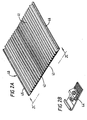
- FIG. 3A shows a screen apparatus 50 for use in, for example a vibratory shaker or shale shaker.
- the screen apparatus has three sub-screens 51, 52, 53 in an integral unit. Alternatively, three sub-screens may be connected together, for example with an interlock fit or suitable fasteners. It is within the scope of this invention to employ two, four or more appropriately sized sub-screens in an integral unit or interconnected.
- Each sub-screen has a series of alternating ridges and valleys 51R, 52R, 53R and 51V, 52V, 53V, respectively.
- Each ridge-valleys is at an angle to hook strip sides SS of each screen, and the angle of the ridge-valley series of sub-screen 52 is different from that of the sub-screens 51 and 53.
- ridges 53R of the sub-screen 53 are lined up with ridges 52R of the sub-screen 52, but it is within the scope of this invention for ridges of any set to be offset with respect to ridges of another set.
- the hook strip sides may be eliminated and any known suitable edge or side structure may be employed.
- Any one of the sub-screens 51, 52, 53 may be eliminated and any two adjacent ridge-valley series in any screen herein may be offset as are the sub-screens in Figure 3A.
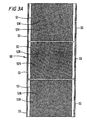
- Figure 4 shows a screen assembly 100 according to the present invention with side hook strips 102 and 104 and a two ridge-valley series 103, 105. Ridges 106 of the series 103 are higher than ridges 107 of the series 105. Any suitable spacing between ridges may be employed.
- the series 103, 105 may be made of any mesh or screen or meshes or screen combination disclosed herein. Any suitable plate, frame, straps or strips may be used with the screen assembly 100; but in one aspect no such item is used.
- particle laden mud flows from the lower height series 105 to the higher height series 103; but it is within the scope of this invention to flow from a higher height series to a lower height series.
- screening material 109, 110 [any screen(s) and/or mesh(es) described herein] is connected to (in any way disclosed herein) an optional flat coarse mesh 111.
- Figure 5B shows a screen assembly 150 comprising side hook strips 151, 152 and a series of ridge-valleys 153.
- Each ridge 154 of the series 153 is higher at one end than the other, as illustrated in Figure 7A. Any desired height difference may be employed and in use, particle laden fluid may flow either way between the sides, from the higher ridge end 155 to the lower end 156, or vice versa.
- a ridge end top 155 is narrower than a ridge end top 156.
- the end 155 may be wider than the end 156.
- Any ridge disclosed herein or any series of ridges disclosed herein may have a height differential from end-to-end (as shown herein) and/or any ridge disclosed herein may have one ridge end of a particular ridge wider than the other end of the ridge and/or with different cross-sectional area.
- the series 153 is made of any screening material [screen(s) and/or mesh(es)] disclosed herein.
- the series 153 is, optionally, connected to a flat coarse screen (any disclosed herein) 157.
- any plate, frame, strap or strips disclosed herein may be used.
Abstract
Description
- The present invention relates to a screen assembly, a vibratory separator and a method of screening.
- When drilling a wellbore in the earth's surface, drilling fluid is used to maintain the tip of a drill cool and to carry solids to the surface of the wellbore. Once at the surface the solids are removed from the drilling fluid which can then be re-used.
- Types of apparatus that can remove solids from drilling fluid include a vibratory separator known as shale shaker. A typical shale shaker is disclosed in WO-A-96/33792. Typically, it is known to provide such equipment with one or more screens of wire mesh for filtering the drilling fluid. Typically, the wire mesh is very fine and does not have a high durability. It is advantageous to have a screen which has high durability.
- Shale shakers are limited in size, especially those used on offshore platforms where space is at a premium. Accordingly, it is advantageous to filter a large quantity of particle laden mud using standard size shale shakers.
- It is also advantageous for screens to be easily replaceable and repairable.
- It is also advantageous to increase the residence period of the particle laden fluid on the screen.
- According to the present invention there is provided a screen assembly for a vibratory separator, the screen assembly comprising a ridge-valley series of screening material having a plurality of alternating ridges and valleys and two spaced apart ends having ridge openings below the ridges, said openings covered with screen or mesh material characterised in that said openings are covered with screen or mesh material in a generally bulbous shape.
- Preferably, the screen assembly further comprises a hook strip connection on spaced-apart sides of said ridge-valley series of screening material.
- Advantageously, the ridges are of at least two different sizes.
- Preferably, the ridges are of at least two different widths.
- Advantageously, the ridges are of a least two different heights.
- Preferably, the screen assembly comprises two side portions and a central portion, wherein said ridges decrease in size from said side portions towards said central portion.
- Advantageously, the ridges decrease in height.
- Preferably, the screening material further comprises at least a second layer of screening material.
- Preferably, the screen assembly comprises a second screen, wherein the ridges of said second screen are in line with the ridges of said first screen.
- Advantageously, the screen assembly further comprises a flat screen of screening material, said ridge-valley series on said flat screen.
- Preferably, the flat screen is made of coarse mesh and said ridge-valley series are made of fine mesh.
- The first aspect of the present invention also provides a vibratory separator comprising a screen assembly of the present invention, the screen assembly comprising a ridge-valley series of screening material having a plurality of alternating ridges and valleys and two spaced apart ends having ridge openings below the ridges, said openings covered with screen or mesh material characterised in that said ends are covered with screen or mesh material in a generally bulbous shape.
- The first aspect of the present invention further provides a method for screening using the vibratory separator of the invention said method comprising the step of vibrating said ridge-valley series of screening material, pouring a particle laden fluid on to one of said ridge-valley series of screening material thereon, allowing fluid and predetermined size particles therethrough, and vibrating particles larger than said predetermined size to a far end of one other of said ridge-valley series of screening material.
- For a better understanding of the present invention, reference will now be made, by way of example, to the accompanying drawings, in which:
- Figure 1A is a perspective view of a screen apparatus according to the invention;
- Figure 1B is an enlarged view of part of the screen apparatus of Figure 1A;
- Figure 1C is a end view taken from
line 1C-1C of Figure 1A; - Figure 1D is a end view of a second embodiment of a second screen, similar to the screen of Figure 1A;
- Figure 1E is a perspective view of a third screen;
- Figure 2A is a perspective view of a screen
apparatus according to the present invention; Figure 2B
is an enlarged view of part of the screen apparatus of
Figure 2A; Figure 2C is a view along
line 2C-2C of Figure 2A; - Figures 2D shows an end shape for ridge end covering according to the present invention;
- Figure 3A is a top view of a screen apparatus according to the present invention; Figure 3B is an end view of the screen apparatus of Figure 3A;
- Figure 4 is a perspective view of a screen according to the present invention;
- Figure 5A is a perspective view of a screen part according to the present invention; and Figure 5B is a perspective view of a screen with parts as in Figure 5A.
-
- Figure 1A to 1D show a screen assembly generally identified by reference numeral 1 for use in, for example, a vibratory shaker such as a shale shaker. The present patent is derived from the earlier EP-A-1.163.037 (parent European Patent Application No. 00 915 179.6) derived from WO-A-00/64558 discloses a screen assembly for a vibratory separator, the screen assembly comprising at least a first and second ridge-valley series of screening material comprising a plurality of alternating ridges and valleys of screening material, each ridge having a ridge end, characterised in that at least the ridge ends of adjacent sides of said first and second ridge-valley series of screening material are offset or overlap when viewed from one end.
- The screen assembly 1 has
hook strips 2 and 4 on either side thereof.Screening material 6 is connected along the length of each hook strip by known methods, for example folding, welding, crimping together, epoxying, press/fiction fit, and/or interlocking of parts. In one aspect no underlying plate, straps, or strips and no frame are used with the screen assembly 1. - The
screening material 6 may be any known screening material, screen and/or mesh or combination thereof and/or any screening material disclosed herein. In the screen 1 as shown, thescreening material 6 includes a lower mesh (for example 1 to 80 mesh) 8 which may be a relatively coarse mesh and an upper mesh 10 (for example 8 to 400 mesh) and which may be a relatively fine mesh. Two fine mesh screens and one coarse mesh screen may also be used. The fine mesh may be bonded to the coarse mesh, sewed to the coarse mesh, glued to it, welded to it, and/or sintered to it. - An optional perforated plate or a series of straps or strips such as those disclosed in WO-A-94/23849, may be used below the coarse mesh. One, two, three or more layers of wire mesh may be used instead of or with such a plate, straps, or strips. In one particular aspect a flat coarse mesh (for example mesh 1 to mesh 12) is used instead of or in addition to a plate, straps, or strips.
- Mesh (fine, coarse, or both) is folded over open exposed ends of
ridges curve shape 15. Such shape can provide more screen area for separation and can deflect and re-route solids and fluid to a subsequent set of valleys. Alternatively any or all openings may be plugged with a solid, porous, or perforated plug glued or welded in place. Alternatively, instead of folding screening material and/or mesh over the ends of ridges, a separate piece of screen, screens, mesh, and/or meshes can be placed at an open ridge end and the edges of the piece attached to, connected to, interlocked with, interwoven with, and/or adhered to the edges of the ridge end opening. Also, it is within the scope of this invention for any ridge end to be closed off to fluid flow, to be covered with screen(s) and/or mesh, and/or to be plugged. It is within the scope of this invention for all ridge ends on one side of a series of ridges (for example onside side - A series of valleys or
troughs 16 is interspersed between the series ofridges 14. A second series ofridges 18 andvalleys 20 is offset from theridges 14/valleys 16, as shown in Figures 1A to 1D. Alternatively, as shown in Figure 1D the shape of one set of ridges RD can overlap (when viewed on end) the ridges RG of the other set of ridges. The ridges RD are also the same size as the ridges RG, as are the valleys. It is within the scope of this invention to employ any desired amount of such overlap. As shown, for example in Figures 1C and 1D, the ridges are of substantially the same height and ridge ends are of substantially the same cross-sectional area. It is also within the scope of this invention for the ridges of one set of ridges to be of a different width than those of the other set; for the one set to be wider or narrower than the second set; for ridges or ridge ends on one set to have a different cross-sectional area than those of another set; and/or to employ three, four, five, six or more series of offset ridges on a single screen.Optional side paths hook strip 2, 4 side or positioned against a frame side (when an optional frame is used) or side member if hook strips are not used. - Figure 1E presents a
screen apparatus 30 with four sets of offsetridges - Figures 2A - 2C show a
screen apparatus 40 for use in, for example a vibratory shaker such as a shale shaker. Thescreen apparatus 40 has a series ofridges 41 andvalleys 42 of screening material 43 (like any of thescreening material 16, Figure 1A). Ends of ridges are, optionally, covered with screen and/or mesh (or, alternatively, plugged as described above with either solid or perforated plugs) in a closed curved shape orbulbous shape 44 or they may be flat. Thescreening material 43 extends between side hook strips 45, 46 on aflat screen 47. As shown in Figure 2C, ridges of the set ofridges 41 may have different heights; for example alternating high and low, high in the middle and lower on the ends, or as shown in Figure 2C higher towards the sides and lower in the middle. Any such series of ridges with height differences, with width differences, and, therefore, with differing cross-sectional area and different amount of surface area may be used for any ridge series or part thereof on any screen disclosed herein. As shown in Figure 2C, the height (and also the cross-sectional area as viewed on end as in Figure 2C) of the ridges may gradually decrease from the sides of the screen assembly to the middle. Alternatively, the height (and cross-sectional area) may increase from the screen sides to the screen middle. - Figure 2D show a possible shape for ridge end coverings for the ends 44 (and for any ridge end disclosed herein). The covering is designated CV-2D.
- Figure 3A shows a
screen apparatus 50 for use in, for example a vibratory shaker or shale shaker. The screen apparatus has threesub-screens valleys sub-screen 52 is different from that of the sub-screens 51 and 53. As shown in Figure 3B,ridges 53R of the sub-screen 53 are lined up withridges 52R of the sub-screen 52, but it is within the scope of this invention for ridges of any set to be offset with respect to ridges of another set. For any screen in Figures 1A - 3A the hook strip sides may be eliminated and any known suitable edge or side structure may be employed. Any one of the sub-screens 51, 52, 53 may be eliminated and any two adjacent ridge-valley series in any screen herein may be offset as are the sub-screens in Figure 3A. - Figure 4 shows a
screen assembly 100 according to the present invention with side hook strips 102 and 104 and a two ridge-valley series Ridges 106 of theseries 103 are higher thanridges 107 of theseries 105. Any suitable spacing between ridges may be employed. Theseries screen assembly 100; but in one aspect no such item is used. In use, particle laden mud flows from thelower height series 105 to thehigher height series 103; but it is within the scope of this invention to flow from a higher height series to a lower height series. As shown screeningmaterial 109, 110 [any screen(s) and/or mesh(es) described herein] is connected to (in any way disclosed herein) an optional flatcoarse mesh 111. - Figure 5B shows a
screen assembly 150 comprising side hook strips 151, 152 and a series of ridge-valleys 153. Eachridge 154 of theseries 153 is higher at one end than the other, as illustrated in Figure 7A. Any desired height difference may be employed and in use, particle laden fluid may flow either way between the sides, from thehigher ridge end 155 to thelower end 156, or vice versa. Also, aridge end top 155 is narrower than aridge end top 156. Alternatively, theend 155 may be wider than theend 156. Any ridge disclosed herein or any series of ridges disclosed herein may have a height differential from end-to-end (as shown herein) and/or any ridge disclosed herein may have one ridge end of a particular ridge wider than the other end of the ridge and/or with different cross-sectional area. Theseries 153 is made of any screening material [screen(s) and/or mesh(es)] disclosed herein. Theseries 153 is, optionally, connected to a flat coarse screen (any disclosed herein) 157. Alternatively or in addition to the screen 1686 any plate, frame, strap or strips disclosed herein may be used. In one particular aspect the linear measurement E1=E2 and A1+B1+C1+D1 = A2+B2+C2+D2, although any suitable desired lengths may be employed, and one end (the end 155) is higher than theend 156. Ridge ends of theassembly 155, 156 (as may be any ridge end disclosed herein) may be covered or plugged in any way as described above.
Claims (13)
- A screen assembly for a vibratory separator, the screen assembly comprising a ridge-valley series of screening material (14, 16; 31, 32, 33, 34; 43) having a plurality of alternating ridges (18; 41) and valleys (20; 42) and two spaced apart ends having ridge openings below the ridges, said openings covered with screen or mesh material characterised in that said openings are covered with screen or mesh material (14; 44) in a generally bulbous shape.
- A screen assembly as claimed in Claim 1, further comprising a hook strip (1,4) connection on spaced-apart sides of said ridge-valley series of screening material (14, 16).
- A screen assembly as claimed in Claim 1 or 2, characterised in that said ridges are of at least two different sizes.
- A screen assembly as claimed in Claim 3, wherein said ridges (41) are of at least two different widths.
- A screen assembly as claimed in Claim 3 or 4, wherein said ridges (41) are of a least two different heights.
- A screen assembly as claimed in Claim 3, 4 or 5, said screen comprising two side portions and a central portion, wherein said ridges (41) decrease in size from said side portions towards said central portion.
- A screen assembly as claimed in Claim 6, wherein said ridges (41) decrease in height.
- A screen assembly as claimed in any of Claims 3 to 7, wherein said screening material (43) further comprises at least a second layer of screening material.
- A screen assembly as claimed in any preceding Claim, comprising a second screen, wherein the ridges of said second screen are in line with the ridges of said first screen.
- A screen assembly as claimed in any of preceding Claim, further comprising a flat screen of screening material, said ridge-valley series on said flat screen.
- A screen assembly as claimed in Claim 10, wherein said flat screen is made of coarse mesh and said ridge-valley series are made of fine mesh.
- A vibratory separator comprising a screen assembly as claimed in any preceding claim.
- A method for screening using the vibratory separator as claimed Claim 12, said method comprising the step of vibrating said ridge-valley series of screening material, pouring a particle laden fluid on to one of said ridge-valley series of screening material thereon, allowing fluid and predetermined size particles therethrough, and vibrating particles larger than said predetermined size to a far end of one other of said ridge-valley series of screening material.
Applications Claiming Priority (3)
| Application Number | Priority Date | Filing Date | Title |
|---|---|---|---|
| US296975 | 1999-04-22 | ||
| US09/296,975 US6290068B1 (en) | 1993-04-30 | 1999-04-22 | Shaker screens and methods of use |
| EP00915179A EP1163037B1 (en) | 1999-04-22 | 2000-03-13 | Screen assembly, vibratory separator and method of screening |
Related Parent Applications (1)
| Application Number | Title | Priority Date | Filing Date |
|---|---|---|---|
| EP00915179A Division EP1163037B1 (en) | 1999-04-22 | 2000-03-13 | Screen assembly, vibratory separator and method of screening |
Publications (2)
| Publication Number | Publication Date |
|---|---|
| EP1179357A1 EP1179357A1 (en) | 2002-02-13 |
| EP1179357B1 true EP1179357B1 (en) | 2003-08-27 |
Family
ID=23144349
Family Applications (2)
| Application Number | Title | Priority Date | Filing Date |
|---|---|---|---|
| EP01204099A Expired - Lifetime EP1179357B1 (en) | 1999-04-22 | 2000-03-13 | Screen assembly, vibratory separator and method of screening |
| EP00915179A Expired - Lifetime EP1163037B1 (en) | 1999-04-22 | 2000-03-13 | Screen assembly, vibratory separator and method of screening |
Family Applications After (1)
| Application Number | Title | Priority Date | Filing Date |
|---|---|---|---|
| EP00915179A Expired - Lifetime EP1163037B1 (en) | 1999-04-22 | 2000-03-13 | Screen assembly, vibratory separator and method of screening |
Country Status (8)
| Country | Link |
|---|---|
| US (1) | US6290068B1 (en) |
| EP (2) | EP1179357B1 (en) |
| AT (2) | ATE246027T1 (en) |
| AU (1) | AU3658000A (en) |
| CA (1) | CA2371171C (en) |
| DE (2) | DE60004184D1 (en) |
| NO (2) | NO323056B1 (en) |
| WO (1) | WO2000064558A1 (en) |
Families Citing this family (49)
| Publication number | Priority date | Publication date | Assignee | Title |
|---|---|---|---|---|
| US6607080B2 (en) * | 1993-04-30 | 2003-08-19 | Varco I/P, Inc. | Screen assembly for vibratory separators |
| US6454099B1 (en) * | 1993-04-30 | 2002-09-24 | Varco I/P, Inc | Vibrator separator screens |
| US6581781B1 (en) * | 1993-04-30 | 2003-06-24 | Tuboscope I/P, Inc. | Vibrator separator screens |
| US20020104611A1 (en) * | 1998-10-30 | 2002-08-08 | Adams Thomas C. | Self-flattening screens for vibratory separators |
| US6769550B2 (en) * | 2002-01-16 | 2004-08-03 | Varco I/P, Inc. | Screen assemblies for shale shakers |
| US6662952B2 (en) * | 2002-01-16 | 2003-12-16 | Varco I/P, Inc. | Shale shakers and screens for them |
| US20050035033A1 (en) * | 1999-03-25 | 2005-02-17 | Adams Thomas C. | Methods for sealing screen assemblies on vibratory separators |
| EP1212130A1 (en) * | 1999-09-16 | 2002-06-12 | Varco I/P, Inc. | A screen for use in a shale shaker and method for using same |
| GB2399515B (en) * | 2001-03-28 | 2005-09-07 | Varco Int | A screen assembly for a vibratory separator |
| US20050103689A1 (en) * | 2001-10-19 | 2005-05-19 | Schulte David L.Jr. | Sealing screen assemblies and vibratory separators |
| US20050224398A1 (en) * | 2001-10-19 | 2005-10-13 | Largent David W | Vibratory separators and sealing screens |
| US20050067327A1 (en) * | 2002-01-16 | 2005-03-31 | Adams Thomas C. | Screen assemblies for shale shakers |
| US20030201237A1 (en) * | 2002-04-26 | 2003-10-30 | Grichar Charles Newton | Shale shakers |
| US20030222032A1 (en) * | 2002-05-29 | 2003-12-04 | Rudiger Tueshaus | Filtering screen construction and methods |
| US20050133465A1 (en) * | 2002-06-12 | 2005-06-23 | Derrick Corporation | Vibratory screen assembly and method of manufacture |
| US7063214B2 (en) * | 2003-02-04 | 2006-06-20 | Varco I/P, Inc. | Interlocking screens for vibratory separators |
| US7484625B2 (en) * | 2003-03-13 | 2009-02-03 | Varco I/P, Inc. | Shale shakers and screens with identification apparatuses |
| DE102004013145B4 (en) * | 2004-03-17 | 2010-04-01 | Airbus Deutschland Gmbh | Method for edge sealing of a core composite |
| NL1025859C2 (en) * | 2004-03-31 | 2005-02-14 | Stork Veco Bv | Electroformed screen for separating sugar crystals from massecuite, has recesses provided in land substrates |
| SE528312C2 (en) * | 2005-05-31 | 2006-10-17 | Sandvik Intellectual Property | Viewing device |
| US20070125687A1 (en) * | 2005-12-01 | 2007-06-07 | Kutryk Edward A | Screen assembly for a vibratory separator |
| US8231010B2 (en) * | 2006-12-12 | 2012-07-31 | Varco I/P, Inc. | Screen assemblies and vibratory separators |
| US20090145816A1 (en) * | 2007-12-11 | 2009-06-11 | Paul William Dufilho | Screen assemblies for shale shakers |
| NO336396B1 (en) * | 2009-10-27 | 2015-08-10 | Optipro As | An improved cell insert filter for a screening machine filter |
| EP2956223B1 (en) * | 2013-02-15 | 2020-12-09 | Aqseptence Group, Inc. | Underdrain assembly |
| CA2910273C (en) * | 2013-04-30 | 2018-05-29 | M-I Drilling Fluids Uk Ltd. | Screen having frame members with angled surface(s) |
| CN104612608A (en) * | 2015-01-30 | 2015-05-13 | 张劲南 | Novel mud solid control system and technology |
| US10428606B2 (en) | 2017-07-12 | 2019-10-01 | Saudi Arabian Oil Company | Collecting drilling microchips |
| US11267018B2 (en) * | 2018-06-12 | 2022-03-08 | Brett Herrington | Shale shaker buffer wear item and method for use |
| US11125075B1 (en) | 2020-03-25 | 2021-09-21 | Saudi Arabian Oil Company | Wellbore fluid level monitoring system |
| US11414963B2 (en) | 2020-03-25 | 2022-08-16 | Saudi Arabian Oil Company | Wellbore fluid level monitoring system |
| US11280178B2 (en) | 2020-03-25 | 2022-03-22 | Saudi Arabian Oil Company | Wellbore fluid level monitoring system |
| US11414985B2 (en) | 2020-05-28 | 2022-08-16 | Saudi Arabian Oil Company | Measuring wellbore cross-sections using downhole caliper tools |
| US11414984B2 (en) | 2020-05-28 | 2022-08-16 | Saudi Arabian Oil Company | Measuring wellbore cross-sections using downhole caliper tools |
| US11631884B2 (en) | 2020-06-02 | 2023-04-18 | Saudi Arabian Oil Company | Electrolyte structure for a high-temperature, high-pressure lithium battery |
| US11391104B2 (en) | 2020-06-03 | 2022-07-19 | Saudi Arabian Oil Company | Freeing a stuck pipe from a wellbore |
| US11149510B1 (en) | 2020-06-03 | 2021-10-19 | Saudi Arabian Oil Company | Freeing a stuck pipe from a wellbore |
| US11719089B2 (en) | 2020-07-15 | 2023-08-08 | Saudi Arabian Oil Company | Analysis of drilling slurry solids by image processing |
| US11255130B2 (en) | 2020-07-22 | 2022-02-22 | Saudi Arabian Oil Company | Sensing drill bit wear under downhole conditions |
| US11506044B2 (en) | 2020-07-23 | 2022-11-22 | Saudi Arabian Oil Company | Automatic analysis of drill string dynamics |
| US11867008B2 (en) | 2020-11-05 | 2024-01-09 | Saudi Arabian Oil Company | System and methods for the measurement of drilling mud flow in real-time |
| WO2022140568A1 (en) * | 2020-12-23 | 2022-06-30 | Continental Wire Cloth, LLC | Shaker screen assembly with undulation sealing tabs |
| US11434714B2 (en) | 2021-01-04 | 2022-09-06 | Saudi Arabian Oil Company | Adjustable seal for sealing a fluid flow at a wellhead |
| US11697991B2 (en) | 2021-01-13 | 2023-07-11 | Saudi Arabian Oil Company | Rig sensor testing and calibration |
| US11572752B2 (en) | 2021-02-24 | 2023-02-07 | Saudi Arabian Oil Company | Downhole cable deployment |
| US11727555B2 (en) | 2021-02-25 | 2023-08-15 | Saudi Arabian Oil Company | Rig power system efficiency optimization through image processing |
| US11846151B2 (en) | 2021-03-09 | 2023-12-19 | Saudi Arabian Oil Company | Repairing a cased wellbore |
| US11624265B1 (en) | 2021-11-12 | 2023-04-11 | Saudi Arabian Oil Company | Cutting pipes in wellbores using downhole autonomous jet cutting tools |
| US11867012B2 (en) | 2021-12-06 | 2024-01-09 | Saudi Arabian Oil Company | Gauge cutter and sampler apparatus |
Family Cites Families (164)
| Publication number | Priority date | Publication date | Assignee | Title |
|---|---|---|---|---|
| US275190A (en) | 1883-04-03 | Sieve for roller-mills | ||
| US236416A (en) | 1881-01-11 | William o | ||
| US526562A (en) | 1894-09-25 | Coal-screen | ||
| US40242A (en) | 1863-10-13 | Improvement in grain-sieves | ||
| US583981A (en) | 1897-06-08 | Fruit-grading machine | ||
| US2677462A (en) | 1954-05-04 | conkling | ||
| US516673A (en) | 1894-03-20 | Sieve | ||
| US500302A (en) | 1893-06-27 | Slate-picker | ||
| US560858A (en) | 1896-05-26 | missroon | ||
| US275340A (en) | 1883-04-03 | kimball | ||
| US607598A (en) | 1898-07-19 | Grain-separating screen for th resh ing-ivlach in es | ||
| US246144A (en) | 1881-08-23 | Fanning-mill | ||
| US268491A (en) | 1882-12-05 | hubbell | ||
| US777317A (en) | 1904-03-25 | 1904-12-13 | John A Traylor | Shaking ore-screen. |
| US865185A (en) | 1906-11-24 | 1907-09-03 | Stephen J Kerrigan | Slate-jig. |
| US964897A (en) | 1908-04-04 | 1910-07-19 | Noah Bryant | Save-all for paper-making machines. |
| US966578A (en) | 1908-04-20 | 1910-08-09 | Sherman P Murphy | Screen for threshing-machines. |
| US948222A (en) | 1909-04-14 | 1910-02-01 | Clarence W Honabach | Shaking-screen. |
| US984866A (en) | 1909-05-06 | 1911-02-21 | Earl H Tate | Aero ore-concentrator and placer-machine. |
| US1132667A (en) | 1910-06-16 | 1915-03-23 | Louis Milliot | Florist's dirt-sieve. |
| US1098979A (en) | 1912-01-22 | 1914-06-02 | Karl Schuchard | Jigging-machine. |
| US1082612A (en) | 1912-10-01 | 1913-12-30 | Lawrence William Smith | Fruit-grading machine. |
| US1139041A (en) | 1914-09-05 | 1915-05-11 | Ole L Larson | Corrugated rotary sieve. |
| US1242982A (en) | 1916-10-16 | 1917-10-16 | Tyler Co W S | Screening device. |
| US1250768A (en) | 1916-10-20 | 1917-12-18 | Charles Hunnicutt | Seed-corn grader. |
| US1248081A (en) | 1916-12-27 | 1917-11-27 | Carrie S Couch | Flour-sifter. |
| US1359426A (en) | 1919-06-11 | 1920-11-16 | Williams Patent Crusher & Pulv | Cage for grinders |
| US1423021A (en) | 1919-09-22 | 1922-07-18 | Tyler Co W S | Screening apparatus |
| US1344747A (en) | 1919-11-07 | 1920-06-29 | Charles V Wright | Shaking-screen |
| US1626774A (en) | 1920-02-03 | 1927-05-03 | Farley G Clark | Method of welding and product thereof |
| US1614586A (en) | 1920-02-27 | 1927-01-18 | E D Anderson Inc | Machine for separating articles |
| US1397339A (en) | 1920-07-22 | 1921-11-15 | Sturtevant Mill Co | Screen-separator |
| US1505735A (en) | 1922-04-12 | 1924-08-19 | Albert H Stebbins | Table concentrator |
| US1462804A (en) | 1922-04-18 | 1923-07-24 | Evans Edward James | Sieve |
| US1713143A (en) | 1924-02-23 | 1929-05-14 | Gustave A Overstrom | Vibrating screen |
| US1561632A (en) | 1924-02-27 | 1925-11-17 | Herbert S Woodward | Perforated indented screen |
| US1716758A (en) | 1924-12-03 | 1929-06-11 | Bland John | Process of separating mica |
| GB269877A (en) | 1926-04-23 | 1928-04-19 | Hermann Schubert | Improvements in sifting apparatus |
| US1678941A (en) | 1927-06-09 | 1928-07-31 | Tyler Co W S | Method of making woven-wire screens |
| US1785195A (en) | 1928-02-07 | 1930-12-16 | Wind Blast Chaffer Company | Chaffer for thrashing machines and grain harvesters |
| US1822298A (en) | 1929-11-08 | 1931-09-08 | Kerrigan Stephen Joseph | Slate jig |
| US1879377A (en) | 1929-12-03 | 1932-09-27 | James W Mcneely | Screen and method of making the same |
| US1950861A (en) | 1931-03-19 | 1934-03-13 | Sr Edward O'toole | Method and apparatus for feeding and separating dry coal from refuse |
| US1997740A (en) | 1931-12-24 | 1935-04-16 | Tyler Co W S | Plural cloth screening apparatus |
| US2052467A (en) | 1931-12-30 | 1936-08-25 | Hermann Rudolf | Wire sifting screen |
| US1997713A (en) | 1932-08-08 | 1935-04-16 | Tyler Co W S | Screen and method of making same |
| US2061850A (en) | 1934-01-29 | 1936-11-24 | Western States Machine Co | Filtering element and the art of producing the same |
| US2082513A (en) | 1934-07-26 | 1937-06-01 | Western States Machine Co | Filter sieve and art of making the same |
| US2104785A (en) | 1934-12-10 | 1938-01-11 | Swan M Akeyson | Vibrating endless screen |
| US2089548A (en) | 1935-03-12 | 1937-08-10 | Colorado Fuel & Iron Corp | Means of filtration |
| GB519680A (en) | 1938-09-22 | 1940-04-03 | James Walker | Improvements in or relating to strainer plates and drums |
| US2251909A (en) | 1939-01-23 | 1941-08-12 | Rotospray Mfg Company | Separation of solid material from liquid material |
| US2274700A (en) | 1939-02-14 | 1942-03-03 | Tyler Co W S | Screening apparatus |
| US2190262A (en) | 1939-03-17 | 1940-02-13 | Geist Adolf | Shaker pan |
| US2335084A (en) | 1940-04-29 | 1943-11-23 | Mission Rubber Company | Sifter |
| US2462878A (en) | 1942-11-23 | 1949-03-01 | Mining Process & Patent Co | Vibrating screen with vacuum control therefor |
| US2406051A (en) | 1943-06-26 | 1946-08-20 | Paul Porzelt | Apparatus for producing corrugated structures |
| US2480320A (en) | 1945-02-10 | 1949-08-30 | Vic Cleaning Machine Co | Filter |
| US2511239A (en) | 1947-01-13 | 1950-06-13 | Simplicity Eng Co | Screen cloth anchoring and tensioning means |
| US2648441A (en) | 1948-01-17 | 1953-08-11 | Productive Equipment Corp | Vibrating equipment |
| US2670079A (en) | 1949-09-20 | 1954-02-23 | Iii Fred K Betts | Attachment for vibratory screens |
| US2667975A (en) | 1950-03-03 | 1954-02-02 | Rudolph V Seaholm | Self-cleaning strainer |
| GB698515A (en) * | 1950-07-21 | 1953-10-14 | American Air Filters Company I | Improvements in or relating to corrugated screen gas impingement filters |
| US2723032A (en) | 1950-12-18 | 1955-11-08 | Mining Process & Patent Co | Vibrating screens |
| US2726184A (en) | 1952-11-01 | 1955-12-06 | Purolator Products Inc | Method of providing seals for filters |
| US2774477A (en) | 1954-12-06 | 1956-12-18 | Iowa Mfg Co Cedar Rapids | Screen clamping mechanism |
| US2827169A (en) | 1954-12-07 | 1958-03-18 | Internat Pulp Products Inc | Screen plate |
| US2813629A (en) | 1955-10-14 | 1957-11-19 | John B Brugmann | Screen support |
| US2800227A (en) | 1955-11-16 | 1957-07-23 | Kiger Fred | Lime sifter |
| GB823648A (en) | 1956-09-27 | 1959-11-18 | Air Maze Corp | Filters for fluids |
| US2902165A (en) | 1957-03-04 | 1959-09-01 | Multi Metal Wire Cloth Co Inc | Filter leaf and method of assembling it |
| US2980208A (en) | 1957-05-21 | 1961-04-18 | Delbag Luftfilter Gmbh | Filter element for extremely fine dust |
| US2973865A (en) | 1957-09-17 | 1961-03-07 | John F Cibula | Rocker screen vibrating machine with undulated screen cloth |
| US3057481A (en) | 1958-06-12 | 1962-10-09 | Pall Corp | Corrugated filter and method of forming the same |
| US2985303A (en) | 1958-09-18 | 1961-05-23 | Wright Wilbur | Quick change, cartridge type, sizing screen, for asphalt plant |
| US2929464A (en) | 1959-05-18 | 1960-03-22 | Vernco Corp | Flat knit filter media |
| US3070231A (en) | 1959-11-23 | 1962-12-25 | Aggregates Equipment Inc | Screening device |
| US3165473A (en) | 1960-10-24 | 1965-01-12 | Pall Corp | Corrugated filter unit |
| US3092573A (en) | 1961-06-26 | 1963-06-04 | Jordan W Lambert | Vibrating screen clamp mechanism |
| US3255885A (en) | 1963-02-27 | 1966-06-14 | Nordberg Manufacturing Co | Vibrating screen |
| US3176643A (en) | 1963-06-26 | 1965-04-06 | Pepperell Mfg Company | Method of making a napped fabric |
| US3285413A (en) | 1964-03-23 | 1966-11-15 | Selector S Aggregates Co Ltd | Screen apparatus |
| US3243943A (en) | 1964-06-15 | 1966-04-05 | American Air Filter Co | Unit filter construction |
| US3542636A (en) | 1965-07-28 | 1970-11-24 | Kurt Wandel | Corrugated board |
| US3464413A (en) | 1967-05-26 | 1969-09-02 | United Merchants & Mfg | Medical bandages |
| US3458978A (en) | 1967-09-12 | 1969-08-05 | Davis Ind Equipment Ltd | Non-planar filter and supporting means |
| US3574103A (en) | 1968-09-06 | 1971-04-06 | Atomic Energy Commission | Laminated cellular material form |
| GB1287851A (en) | 1969-03-05 | 1972-09-06 | ||
| US3747770A (en) | 1969-06-20 | 1973-07-24 | Zurn Ind Inc | Filter screen |
| US3716138A (en) | 1970-05-13 | 1973-02-13 | Hoyt Wire Cloth Co | Screen |
| US3679057A (en) | 1970-09-11 | 1972-07-25 | Damasco Rodolfo Adelto Perez | Screen filter pack and method for making same |
| US3747772A (en) | 1971-05-21 | 1973-07-24 | Parker Hannifin Corp | Filter |
| US3853529A (en) | 1971-06-09 | 1974-12-10 | Farr Co | Pleated air filter cartridge |
| US3789498A (en) | 1971-11-01 | 1974-02-05 | Ambac Ind | Method of diffusion bonding |
| GB1412975A (en) | 1971-11-18 | 1975-11-05 | Kralovopolska Strojirna | Filters |
| US3793692A (en) | 1972-12-12 | 1974-02-26 | American Air Filter Co | Fluid treating filter |
| US3900628A (en) | 1973-06-13 | 1975-08-19 | Linatex Corp Of America | Pretensioned screen panel |
| US4033865A (en) | 1974-12-09 | 1977-07-05 | Derrick Manufacturing Corporation | Non-clogging screen apparatus |
| US3943054A (en) | 1974-12-19 | 1976-03-09 | Durex Products, Inc. | Segmented screen body |
| US4022596A (en) | 1975-08-27 | 1977-05-10 | Pedersen George C | Porous packing and separator medium |
| US4019987A (en) | 1976-01-14 | 1977-04-26 | Leonard L | Extended area filters |
| US4075106A (en) * | 1976-05-07 | 1978-02-21 | Masahiko Yamazaki | Filtering device |
| US4138303A (en) * | 1977-04-21 | 1979-02-06 | Taylor Sr John J | Method of forming screen packs |
| US4380494A (en) * | 1980-04-14 | 1983-04-19 | Litton Systems, Inc. | Vibrating screen with self-supporting screen cloth |
| US4410427A (en) * | 1981-11-02 | 1983-10-18 | Donaldson Company, Inc. | Fluid filtering device |
| ATE30175T1 (en) * | 1981-11-24 | 1987-10-15 | Ici Plc | ELECTRODE STRUCTURE FOR USE IN A FILTER PRESS TYPE ELECTROLYTIC CELL. |
| US4546783A (en) | 1983-05-02 | 1985-10-15 | Flo Trend Shares, Inc. | Apparatus for washing drill cuttings |
| US4472473A (en) | 1983-07-01 | 1984-09-18 | The United States Of America As Represented By The Administrator Of The National Aeronautics And Space Administration | Curved cap corrugated sheet |
| EP0154845A3 (en) * | 1984-02-24 | 1986-06-18 | Sartorius GmbH. | Flat filter element for the filtration of fluids |
| US4575421A (en) * | 1984-03-08 | 1986-03-11 | Derrick Manufacturing Corporation | Non-clogging wear-reducing screen assembly for vibrating screening machine |
| US4582597A (en) | 1984-04-04 | 1986-04-15 | Sweco, Incorporated | Vibratory screen separator |
| GB8418658D0 (en) * | 1984-07-21 | 1984-08-22 | Thule United Ltd | Filtering screens |
| US4617122A (en) * | 1984-08-01 | 1986-10-14 | Donaldson Company, Inc. | Crimp seal pleated filter assembly |
| US4634535A (en) | 1985-03-25 | 1987-01-06 | Lott W Gerald | Drilling mud cleaning method and apparatus |
| US4819809A (en) | 1985-09-09 | 1989-04-11 | Derrick Manufacturing Corporation | Reinforced polyurethane vibratory screen |
| US4696751A (en) * | 1986-08-04 | 1987-09-29 | Dresser Industries, Inc. | Vibratory screening apparatus and method for removing suspended solids from liquid |
| US4857176A (en) | 1986-08-04 | 1989-08-15 | Derrick Manufacturing Corporation | Reinforced molded polyurethane vibratory screen |
| US4769968A (en) | 1987-03-05 | 1988-09-13 | The United States Of America As Represented By The Administrator Of The National Aeronautics And Space Administration | Truss-core corrugation for compressive loads |
| US4820407A (en) * | 1987-04-24 | 1989-04-11 | Cpi Sales, Inc. | Solids screens |
| US4940500A (en) | 1987-08-31 | 1990-07-10 | Tsuchiya Mfg. Co., Ltd. | Filter medium forming system and process |
| GB2210292B (en) | 1987-09-26 | 1991-07-03 | Polydeck Screen Corp | Screening panels and screen decks |
| US4954249A (en) | 1988-06-10 | 1990-09-04 | Beloit Corporation | Wave screen plate |
| US5084178A (en) * | 1988-06-15 | 1992-01-28 | Pall Corporation | Corrugated filter arrangement with support layer and flow channels |
| US4832834A (en) * | 1988-07-11 | 1989-05-23 | Baird Jr Howard R | Elastomer sieve screen |
| US4882054A (en) * | 1988-08-22 | 1989-11-21 | Derrick Manufacturing Corporation | Vibratory screening machine with tiltable screen frame and adjustable discharge weir |
| US5137622A (en) | 1988-09-27 | 1992-08-11 | United Wire Limited | Filter screen assembly |
| AU608392B2 (en) | 1988-09-29 | 1991-03-28 | Manfred Franz Axel Freissle | Screening arrangement |
| DE8812647U1 (en) | 1988-10-08 | 1988-12-01 | Ludwig Krieger Draht- Und Kunststofferzeugnisse Gmbh, 7500 Karlsruhe, De | |
| US5028474A (en) | 1989-07-25 | 1991-07-02 | Czaplicki Ronald M | Cellular core structure providing gridlike bearing surfaces on opposing parallel planes of the formed core |
| US5139154A (en) | 1989-12-27 | 1992-08-18 | Beloit Corporation | Wear screen plate and method of manufacture thereof |
| DE4002078C1 (en) | 1990-01-25 | 1991-05-02 | Fa. Carl Freudenberg, 6940 Weinheim, De | |
| US5162143A (en) | 1990-03-30 | 1992-11-10 | The United States Of America As Represented By The Administrator, National Aeronautics And Space Administration | Core design for use with precision composite reflectors |
| US5221008A (en) * | 1990-05-11 | 1993-06-22 | Derrick Manufacturing Corporation | Vibratory screening machine and non-clogging wear-reducing screen assembly therefor |
| RU2002006C1 (en) * | 1991-04-22 | 1993-10-30 | Борис Алексеевич Негриенко | Sound-absorbing device |
| US5190651A (en) * | 1991-06-24 | 1993-03-02 | Sta-Rite Industries, Inc. | Filter cartridge |
| US5211291A (en) * | 1991-11-07 | 1993-05-18 | Derrick Manufacturing Corporation | Vibratory separator plate for flake-like members |
| US5256292A (en) * | 1992-04-16 | 1993-10-26 | Cagle William S | Screen for filtering undesirable particles from a liquid |
| US5312508A (en) * | 1992-10-16 | 1994-05-17 | John Chisholm | Attaching crimped wire mesh to an object requiring heat transfer |
| US5330057A (en) * | 1993-01-08 | 1994-07-19 | Derrick Manufacturing Corporation | Screen and screen cloth for vibratory machine and method of manufacture thereof |
| US6000556A (en) | 1993-01-13 | 1999-12-14 | Derrick Manufacturing Corporation | Screen assembly for vibratory screening machine |
| US5417858A (en) | 1993-01-13 | 1995-05-23 | Derrick Manufacturing Corporation | Screen assembly for vibrating screening machine |
| ES2135563T3 (en) | 1993-01-13 | 1999-11-01 | Derrick Mfg Corp | WAVY SCREEN FOR A VIBRATORY SCREENING MACHINE AND MANUFACTURING METHOD THEREOF. |
| US5958236A (en) | 1993-01-13 | 1999-09-28 | Derrick Manufacturing Corporation | Undulating screen for vibratory screening machine and method of fabrication thereof |
| DE4310129C1 (en) * | 1993-03-29 | 1994-09-22 | Erno Raumfahrttechnik Gmbh | Filter element |
| EP0693004B1 (en) * | 1993-04-08 | 1999-08-04 | Tuboscope I/P Inc. | Screen for separating solids from drilling fluid |
| US5385669A (en) * | 1993-04-30 | 1995-01-31 | Environmental Procedures, Inc. | Mining screen device and grid structure therefor |
| US5598930A (en) * | 1995-07-20 | 1997-02-04 | Advanced Wirecloth, Inc. | Shale shaker screen |
| US5971159A (en) * | 1993-04-30 | 1999-10-26 | Tuboscope I/P, Inc. | Screen assembly for a vibratory separator |
| US5392925A (en) * | 1993-08-12 | 1995-02-28 | Environmental Procedures, Inc. | Shale shaker and screen |
| US5490598A (en) * | 1994-03-30 | 1996-02-13 | Drexel Oilfield Services, Inc. | Screen for vibrating separator |
| USH1481H (en) * | 1993-06-23 | 1995-09-05 | The United States Of America As Represented By The Secretary Of The Navy | Offset corrugated sandwich construction |
| US5614094A (en) | 1994-05-13 | 1997-03-25 | Deister Machine Co., Inc. | Vibrating screen unit |
| US5551575A (en) * | 1994-07-29 | 1996-09-03 | Environmental Procedures, Inc. | Shale shaker screens |
| US5641070A (en) * | 1995-04-26 | 1997-06-24 | Environmental Procedures, Inc. | Shale shaker |
| US5636749A (en) | 1995-05-18 | 1997-06-10 | Derrick Manufacturing Corporation | Undulating screen for vibratory screening machine |
| US5992641A (en) | 1995-06-05 | 1999-11-30 | Ecc International Inc. | Methods and apparatus for screening particulate materials |
| CA2187963C (en) | 1995-11-03 | 2001-04-10 | Stephen Proulx | Filter cartridge construction and process for filtering particle-containing paint compositions |
| US5851393A (en) | 1995-11-14 | 1998-12-22 | Emerson Electric Co. | Screen assembly |
| DE19631849C1 (en) | 1996-08-07 | 1998-01-08 | Svedala Gfa Aufbereitungsmasch | Vibration drive for a screening machine |
| US6006923A (en) | 1997-06-17 | 1999-12-28 | Tandem Products, Inc. | Screening apparatus |
| US5967336A (en) | 1997-09-02 | 1999-10-19 | Southwestern Wire Cloth, Inc. | Vibrating screen assembly with improved frame |
| US6019228A (en) | 1997-12-31 | 2000-02-01 | Duggan; John C. | Vibrating screen deck support framework system |
| US5950841A (en) | 1998-07-22 | 1999-09-14 | Emerson Electric Co. | Screen assembly for a vibratory separator |
| US6053331A (en) * | 1998-11-17 | 2000-04-25 | Cravello; William M. | Non-tensioned shaker filter |
-
1999
- 1999-04-22 US US09/296,975 patent/US6290068B1/en not_active Expired - Lifetime
-
2000
- 2000-03-13 AT AT00915179T patent/ATE246027T1/en not_active IP Right Cessation
- 2000-03-13 EP EP01204099A patent/EP1179357B1/en not_active Expired - Lifetime
- 2000-03-13 AT AT01204099T patent/ATE248012T1/en not_active IP Right Cessation
- 2000-03-13 WO PCT/EP2000/002216 patent/WO2000064558A1/en active IP Right Grant
- 2000-03-13 AU AU36580/00A patent/AU3658000A/en not_active Abandoned
- 2000-03-13 DE DE60004184T patent/DE60004184D1/en not_active Expired - Lifetime
- 2000-03-13 DE DE60004816T patent/DE60004816D1/en not_active Expired - Lifetime
- 2000-03-13 EP EP00915179A patent/EP1163037B1/en not_active Expired - Lifetime
- 2000-03-13 CA CA2371171A patent/CA2371171C/en not_active Expired - Lifetime
-
2001
- 2001-10-22 NO NO20015165A patent/NO323056B1/en not_active IP Right Cessation
-
2006
- 2006-02-17 NO NO20060761A patent/NO20060761L/en not_active Application Discontinuation
Also Published As
| Publication number | Publication date |
|---|---|
| EP1163037A1 (en) | 2001-12-19 |
| ATE246027T1 (en) | 2003-08-15 |
| DE60004184D1 (en) | 2003-09-04 |
| CA2371171C (en) | 2010-06-01 |
| EP1179357A1 (en) | 2002-02-13 |
| NO323056B1 (en) | 2006-12-27 |
| NO20015165L (en) | 2001-12-11 |
| CA2371171A1 (en) | 2000-11-02 |
| AU3658000A (en) | 2000-11-10 |
| DE60004816D1 (en) | 2003-10-02 |
| NO20015165D0 (en) | 2001-10-22 |
| EP1163037B1 (en) | 2003-07-30 |
| US6290068B1 (en) | 2001-09-18 |
| ATE248012T1 (en) | 2003-09-15 |
| WO2000064558A1 (en) | 2000-11-02 |
| NO20060761L (en) | 2001-12-11 |
Similar Documents
| Publication | Publication Date | Title |
|---|---|---|
| EP1179357B1 (en) | Screen assembly, vibratory separator and method of screening | |
| EP1305100B1 (en) | A screen arrangement and a support structure for a vibratory separator | |
| AU693086B2 (en) | Screen assembly for vibrating screening machine | |
| US20020043485A1 (en) | Unibody structure for screen assembly | |
| US6454099B1 (en) | Vibrator separator screens | |
| US6401934B1 (en) | Ramped screen & vibratory separator system | |
| US7000776B2 (en) | Screen assembly for vibratory separators | |
| US6722504B2 (en) | Vibratory separators and screens | |
| US6269953B1 (en) | Vibratory separator screen assemblies | |
| US5971159A (en) | Screen assembly for a vibratory separator | |
| CA2523601C (en) | Screen assembly for a vibratory separator | |
| CA2469352C (en) | A screen assembly for a vibratory separator | |
| WO2003061855A1 (en) | An apparatus for separating material | |
| US6241098B1 (en) | Drilling fluid treatment operations and apparatuses | |
| GB2399515A (en) | A screen assembly | |
| US6457588B1 (en) | Treatment of fluid having lost circulation material | |
| US20200230653A1 (en) | Screening Material and Screen Assembly | |
| US10758942B2 (en) | Clip and seal assembly | |
| CA2381726C (en) | A screen for use in a shale shaker and method for using same | |
| AU714591B2 (en) | Screen assembly for vibrating screening machine | |
| WO2004035231A1 (en) | A screen for a vibratory separator | |
| MXPA98007572A (en) | Cover for dren |
Legal Events
| Date | Code | Title | Description |
|---|---|---|---|
| PUAI | Public reference made under article 153(3) epc to a published international application that has entered the european phase |
Free format text: ORIGINAL CODE: 0009012 |
|
| AC | Divisional application: reference to earlier application |
Ref document number: 1163037 Country of ref document: EP |
|
| AK | Designated contracting states |
Kind code of ref document: A1 Designated state(s): AT BE CH CY DE DK ES FI FR GB GR IE IT LI LU MC NL PT SE |
|
| AX | Request for extension of the european patent |
Free format text: AL;LT;LV;MK;RO;SI |
|
| 17P | Request for examination filed |
Effective date: 20011227 |
|
| 17Q | First examination report despatched |
Effective date: 20020906 |
|
| AKX | Designation fees paid |
Free format text: AT BE CH CY DE DK ES FI FR GB GR IE IT LI LU MC NL PT SE |
|
| GRAH | Despatch of communication of intention to grant a patent |
Free format text: ORIGINAL CODE: EPIDOS IGRA |
|
| GRAH | Despatch of communication of intention to grant a patent |
Free format text: ORIGINAL CODE: EPIDOS IGRA |
|
| GRAA | (expected) grant |
Free format text: ORIGINAL CODE: 0009210 |
|
| AC | Divisional application: reference to earlier application |
Ref document number: 1163037 Country of ref document: EP Kind code of ref document: P |
|
| AK | Designated contracting states |
Designated state(s): AT BE CH CY DE DK ES FI FR GB GR IE IT LI LU MC NL PT SE |
|
| PG25 | Lapsed in a contracting state [announced via postgrant information from national office to epo] |
Ref country code: AT Free format text: LAPSE BECAUSE OF FAILURE TO SUBMIT A TRANSLATION OF THE DESCRIPTION OR TO PAY THE FEE WITHIN THE PRESCRIBED TIME-LIMIT Effective date: 20030827 Ref country code: BE Free format text: LAPSE BECAUSE OF FAILURE TO SUBMIT A TRANSLATION OF THE DESCRIPTION OR TO PAY THE FEE WITHIN THE PRESCRIBED TIME-LIMIT Effective date: 20030827 Ref country code: FI Free format text: LAPSE BECAUSE OF FAILURE TO SUBMIT A TRANSLATION OF THE DESCRIPTION OR TO PAY THE FEE WITHIN THE PRESCRIBED TIME-LIMIT Effective date: 20030827 Ref country code: CY Free format text: LAPSE BECAUSE OF FAILURE TO SUBMIT A TRANSLATION OF THE DESCRIPTION OR TO PAY THE FEE WITHIN THE PRESCRIBED TIME-LIMIT Effective date: 20030827 Ref country code: CH Free format text: LAPSE BECAUSE OF FAILURE TO SUBMIT A TRANSLATION OF THE DESCRIPTION OR TO PAY THE FEE WITHIN THE PRESCRIBED TIME-LIMIT Effective date: 20030827 Ref country code: FR Free format text: LAPSE BECAUSE OF FAILURE TO SUBMIT A TRANSLATION OF THE DESCRIPTION OR TO PAY THE FEE WITHIN THE PRESCRIBED TIME-LIMIT Effective date: 20030827 Ref country code: LI Free format text: LAPSE BECAUSE OF FAILURE TO SUBMIT A TRANSLATION OF THE DESCRIPTION OR TO PAY THE FEE WITHIN THE PRESCRIBED TIME-LIMIT Effective date: 20030827 Ref country code: NL Free format text: LAPSE BECAUSE OF FAILURE TO SUBMIT A TRANSLATION OF THE DESCRIPTION OR TO PAY THE FEE WITHIN THE PRESCRIBED TIME-LIMIT Effective date: 20030827 Ref country code: IT Free format text: LAPSE BECAUSE OF FAILURE TO SUBMIT A TRANSLATION OF THE DESCRIPTION OR TO PAY THE FEE WITHIN THE PRESCRIBED TIME-LIMIT;WARNING: LAPSES OF ITALIAN PATENTS WITH EFFECTIVE DATE BEFORE 2007 MAY HAVE OCCURRED AT ANY TIME BEFORE 2007. THE CORRECT EFFECTIVE DATE MAY BE DIFFERENT FROM THE ONE RECORDED. Effective date: 20030827 |
|
| REG | Reference to a national code |
Ref country code: GB Ref legal event code: FG4D |
|
| REG | Reference to a national code |
Ref country code: CH Ref legal event code: EP |
|
| REG | Reference to a national code |
Ref country code: IE Ref legal event code: FG4D |
|
| REF | Corresponds to: |
Ref document number: 60004816 Country of ref document: DE Date of ref document: 20031002 Kind code of ref document: P |
|
| PG25 | Lapsed in a contracting state [announced via postgrant information from national office to epo] |
Ref country code: SE Free format text: LAPSE BECAUSE OF FAILURE TO SUBMIT A TRANSLATION OF THE DESCRIPTION OR TO PAY THE FEE WITHIN THE PRESCRIBED TIME-LIMIT Effective date: 20031127 Ref country code: GR Free format text: LAPSE BECAUSE OF FAILURE TO SUBMIT A TRANSLATION OF THE DESCRIPTION OR TO PAY THE FEE WITHIN THE PRESCRIBED TIME-LIMIT Effective date: 20031127 Ref country code: DK Free format text: LAPSE BECAUSE OF FAILURE TO SUBMIT A TRANSLATION OF THE DESCRIPTION OR TO PAY THE FEE WITHIN THE PRESCRIBED TIME-LIMIT Effective date: 20031127 |
|
| PG25 | Lapsed in a contracting state [announced via postgrant information from national office to epo] |
Ref country code: DE Free format text: LAPSE BECAUSE OF FAILURE TO SUBMIT A TRANSLATION OF THE DESCRIPTION OR TO PAY THE FEE WITHIN THE PRESCRIBED TIME-LIMIT Effective date: 20031128 |
|
| PG25 | Lapsed in a contracting state [announced via postgrant information from national office to epo] |
Ref country code: ES Free format text: LAPSE BECAUSE OF FAILURE TO SUBMIT A TRANSLATION OF THE DESCRIPTION OR TO PAY THE FEE WITHIN THE PRESCRIBED TIME-LIMIT Effective date: 20031208 |
|
| PG25 | Lapsed in a contracting state [announced via postgrant information from national office to epo] |
Ref country code: PT Free format text: LAPSE BECAUSE OF FAILURE TO SUBMIT A TRANSLATION OF THE DESCRIPTION OR TO PAY THE FEE WITHIN THE PRESCRIBED TIME-LIMIT Effective date: 20040127 |
|
| NLV1 | Nl: lapsed or annulled due to failure to fulfill the requirements of art. 29p and 29m of the patents act | ||
| PG25 | Lapsed in a contracting state [announced via postgrant information from national office to epo] |
Ref country code: LU Free format text: LAPSE BECAUSE OF NON-PAYMENT OF DUE FEES Effective date: 20040313 |
|
| PG25 | Lapsed in a contracting state [announced via postgrant information from national office to epo] |
Ref country code: IE Free format text: LAPSE BECAUSE OF NON-PAYMENT OF DUE FEES Effective date: 20040315 |
|
| REG | Reference to a national code |
Ref country code: CH Ref legal event code: PL |
|
| PG25 | Lapsed in a contracting state [announced via postgrant information from national office to epo] |
Ref country code: MC Free format text: LAPSE BECAUSE OF NON-PAYMENT OF DUE FEES Effective date: 20040331 |
|
| PLBE | No opposition filed within time limit |
Free format text: ORIGINAL CODE: 0009261 |
|
| STAA | Information on the status of an ep patent application or granted ep patent |
Free format text: STATUS: NO OPPOSITION FILED WITHIN TIME LIMIT |
|
| 26N | No opposition filed |
Effective date: 20040528 |
|
| EN | Fr: translation not filed | ||
| REG | Reference to a national code |
Ref country code: IE Ref legal event code: MM4A |
|
| PGFP | Annual fee paid to national office [announced via postgrant information from national office to epo] |
Ref country code: GB Payment date: 20190313 Year of fee payment: 20 |
|
| REG | Reference to a national code |
Ref country code: GB Ref legal event code: PE20 Expiry date: 20200312 |
|
| PG25 | Lapsed in a contracting state [announced via postgrant information from national office to epo] |
Ref country code: GB Free format text: LAPSE BECAUSE OF EXPIRATION OF PROTECTION Effective date: 20200312 |