EP1185962B1 - Low-power radio frequency identification reader - Google Patents
Low-power radio frequency identification reader Download PDFInfo
- Publication number
- EP1185962B1 EP1185962B1 EP00928301A EP00928301A EP1185962B1 EP 1185962 B1 EP1185962 B1 EP 1185962B1 EP 00928301 A EP00928301 A EP 00928301A EP 00928301 A EP00928301 A EP 00928301A EP 1185962 B1 EP1185962 B1 EP 1185962B1
- Authority
- EP
- European Patent Office
- Prior art keywords
- reader
- radio
- tag
- tag reader
- frequency
- Prior art date
- Legal status (The legal status is an assumption and is not a legal conclusion. Google has not performed a legal analysis and makes no representation as to the accuracy of the status listed.)
- Expired - Lifetime
Links
- 230000004044 response Effects 0.000 claims description 27
- 230000033001 locomotion Effects 0.000 claims description 11
- 230000000763 evoking effect Effects 0.000 claims description 9
- 230000008859 change Effects 0.000 claims description 7
- 238000002604 ultrasonography Methods 0.000 claims description 6
- 230000001939 inductive effect Effects 0.000 claims description 5
- 230000003213 activating effect Effects 0.000 claims description 4
- 238000000034 method Methods 0.000 claims description 3
- 238000002310 reflectometry Methods 0.000 claims 2
- 230000014155 detection of activity Effects 0.000 abstract 1
- 238000012544 monitoring process Methods 0.000 abstract 1
- 238000005516 engineering process Methods 0.000 description 4
- 230000005540 biological transmission Effects 0.000 description 3
- 238000010586 diagram Methods 0.000 description 3
- 230000005855 radiation Effects 0.000 description 3
- 230000035945 sensitivity Effects 0.000 description 3
- 230000004913 activation Effects 0.000 description 1
- 238000001994 activation Methods 0.000 description 1
- 238000001514 detection method Methods 0.000 description 1
- 230000003467 diminishing effect Effects 0.000 description 1
- 238000012986 modification Methods 0.000 description 1
- 230000004048 modification Effects 0.000 description 1
- 238000006467 substitution reaction Methods 0.000 description 1
- 230000002618 waking effect Effects 0.000 description 1
Images
Classifications
-
- G—PHYSICS
- G06—COMPUTING; CALCULATING OR COUNTING
- G06K—GRAPHICAL DATA READING; PRESENTATION OF DATA; RECORD CARRIERS; HANDLING RECORD CARRIERS
- G06K7/00—Methods or arrangements for sensing record carriers, e.g. for reading patterns
- G06K7/10—Methods or arrangements for sensing record carriers, e.g. for reading patterns by electromagnetic radiation, e.g. optical sensing; by corpuscular radiation
- G06K7/10009—Methods or arrangements for sensing record carriers, e.g. for reading patterns by electromagnetic radiation, e.g. optical sensing; by corpuscular radiation sensing by radiation using wavelengths larger than 0.1 mm, e.g. radio-waves or microwaves
- G06K7/10118—Methods or arrangements for sensing record carriers, e.g. for reading patterns by electromagnetic radiation, e.g. optical sensing; by corpuscular radiation sensing by radiation using wavelengths larger than 0.1 mm, e.g. radio-waves or microwaves the sensing being preceded by at least one preliminary step
- G06K7/10128—Methods or arrangements for sensing record carriers, e.g. for reading patterns by electromagnetic radiation, e.g. optical sensing; by corpuscular radiation sensing by radiation using wavelengths larger than 0.1 mm, e.g. radio-waves or microwaves the sensing being preceded by at least one preliminary step the step consisting of detection of the presence of one or more record carriers in the vicinity of the interrogation device
-
- G—PHYSICS
- G06—COMPUTING; CALCULATING OR COUNTING
- G06K—GRAPHICAL DATA READING; PRESENTATION OF DATA; RECORD CARRIERS; HANDLING RECORD CARRIERS
- G06K7/00—Methods or arrangements for sensing record carriers, e.g. for reading patterns
- G06K7/0008—General problems related to the reading of electronic memory record carriers, independent of its reading method, e.g. power transfer
-
- G—PHYSICS
- G06—COMPUTING; CALCULATING OR COUNTING
- G06K—GRAPHICAL DATA READING; PRESENTATION OF DATA; RECORD CARRIERS; HANDLING RECORD CARRIERS
- G06K7/00—Methods or arrangements for sensing record carriers, e.g. for reading patterns
- G06K7/10—Methods or arrangements for sensing record carriers, e.g. for reading patterns by electromagnetic radiation, e.g. optical sensing; by corpuscular radiation
- G06K7/10009—Methods or arrangements for sensing record carriers, e.g. for reading patterns by electromagnetic radiation, e.g. optical sensing; by corpuscular radiation sensing by radiation using wavelengths larger than 0.1 mm, e.g. radio-waves or microwaves
- G06K7/10198—Methods or arrangements for sensing record carriers, e.g. for reading patterns by electromagnetic radiation, e.g. optical sensing; by corpuscular radiation sensing by radiation using wavelengths larger than 0.1 mm, e.g. radio-waves or microwaves setting parameters for the interrogator, e.g. programming parameters and operating modes
- G06K7/10207—Methods or arrangements for sensing record carriers, e.g. for reading patterns by electromagnetic radiation, e.g. optical sensing; by corpuscular radiation sensing by radiation using wavelengths larger than 0.1 mm, e.g. radio-waves or microwaves setting parameters for the interrogator, e.g. programming parameters and operating modes parameter settings related to power consumption of the interrogator
-
- H04B5/77—
-
- Y—GENERAL TAGGING OF NEW TECHNOLOGICAL DEVELOPMENTS; GENERAL TAGGING OF CROSS-SECTIONAL TECHNOLOGIES SPANNING OVER SEVERAL SECTIONS OF THE IPC; TECHNICAL SUBJECTS COVERED BY FORMER USPC CROSS-REFERENCE ART COLLECTIONS [XRACs] AND DIGESTS
- Y02—TECHNOLOGIES OR APPLICATIONS FOR MITIGATION OR ADAPTATION AGAINST CLIMATE CHANGE
- Y02D—CLIMATE CHANGE MITIGATION TECHNOLOGIES IN INFORMATION AND COMMUNICATION TECHNOLOGIES [ICT], I.E. INFORMATION AND COMMUNICATION TECHNOLOGIES AIMING AT THE REDUCTION OF THEIR OWN ENERGY USE
- Y02D30/00—Reducing energy consumption in communication networks
- Y02D30/70—Reducing energy consumption in communication networks in wireless communication networks
Definitions
- This invention relates to radio-frequency identification readers used in conjunction with identification tags in controlled access systems, and more particularly is directed to low power proximity readers suitable for battery powered operation.
- Radio Frequency Identification Systems have come into widespread usage and generally include a reader, typically installed in a fixed location, and a population of portable identification tags. Each ID tag contains a transponder unit which returns a coded response when interrogated by a radio-frequency transmission from the reader. The reader periodically sends out a transmission designed to evoke a radio-frequency response from any ID tags within range of the reader. The tag response includes coded identification data based on which the reader makes a decision to grant or deny access to controlled facilities. RFID systems may use active tags which carry their own source of power such as a battery, or passive tags which contain no source of power and instead rely entirely on energy radiated by the reader unit.
- Passive tag readers continually or periodically search for the presence of passive tags in the vicinity of the reader by transmitting energy which will activate any tag present.
- a passive tag does not announce its presence unless activated by the reader.
- the passive ID tag requires that it receive sufficient radio-frequency power which, when converted by the tag into the electrical current, will support operation of the tag's electronic circuits. Consequently, the operating range of the reader/tag system is to a large extent determined by the power transmitted by the reader, and the ID tag must come into sufficient proximity to the reader for the tag to be activated. For this reason passive tag readers are also know as proximity readers.
- Proximity readers typically have substantially greater operating power requirements than active tag RFID readers of comparable range, and the development of portable battery powered proximity readers has been hindered by excessive power drain on the batteries.
- the present invention addresses the aforementioned need by providing a low power radio-frequency identification reader system which includes a RFID tag reader operative for detecting and verifying the presence of identification tags present within a sensing field of the reader by evoking a radio-frequency response from the identification tags, and a secondary detector operative for detecting a change in the sensing field of the RFID tag reader indicative of the possible entry of an identification tag into the reader's sensing field and deriving an enabling signal responsive to such a change.
- the secondary detector serves to detect the entry of an object into the sensing field but by means other than evoking a radio-frequency response from such an object.
- a power supply is provided for supplying operating power to the RFID tag reader and to the secondary detector.
- the detector and the reader each have an average, operating power requirement, and the secondary detector is selected to have a substantially smaller average operating power requirement than the reader.
- a power switching circuit normally limits or cuts off power from the power supply to the RFID tag reader while supplying the secondary detector. Full operating power to the RFID tag reader is enabled by the power switching circuit for a limited period of time in response to the enabling signal in order to verify the presence of an ID tag and, if so, to permit access to the controlled facilities.
- the RFID reader is relegated to a low duty cycle relative to the secondary detector and the overall or average operating power of the reader system is conserved by only operating the RFID tag reader briefly upon detection of a physical change such as movement in the readers sensing field indicative of the possible presence of an ID tag.
- the low power RFID tag reader system of this invention is not limited to any particular type of RFID reader, it will be found most useful with proximity or passive tag readers because of their relatively high operating power requirements. For this reason, in a preferred form of the invention, the RFID reader is a proximity reader designed to detect the presence of passive identification tags.
- the secondary detector is not limited to any particular sensing technology. Rather, the secondary detector should be chosen to draw little power as compared to the RFID reader so that a significant power savings can be realized by reducing the duty cycle of the RFID reader and relying instead on the secondary detector most of the time.
- the secondary detector may, for example and without limitation, be selected from the group comprised of passive infrared, inductive, capacitive, microwave and ultrasound detectors. Generally the secondary detector operates as a motion detector since the changes to which it responds are normally brought about by movement of objects which are not necessarily ID tags.
- a presently preferred secondary detector is a passive infrared sensor designed to sense changes in the infrared background in the reader's sensing field.
- Power savings may be optimized by limiting operation of the RFID reader to approximately the time period required to verify the presence of an ID tag, i.e., to transmit a radio-frequency interrogation signal, to receive and decode a response from an ID tag if present in the sensing field, and if an ID tag is detected, to execute an access control function such as unlocking a door and then locking it again.
- the tag reader Upon completion of the tag read function or access control function, the tag reader outputs a disabling or off control signal to the power control switch for returning the tag reader to a power limited wait state.
- This invention also extends to a method of operating a radio-frequency identification tag reader having a sensing field, comprising the steps of placing the RFID reader in a wait state or sleep mode, detecting the introduction of an object into the sensing field, activating or waking the radio-frequency reader for a relatively short period of time at least sufficient for evoking a response from an identification tag if present in the sensing field; and returning the radio-frequency proximity reader to the wait state or sleep mode.
- the step of detecting may include sensing a change in a physical characteristic within the sensing field such as a change in position of an object not necessarily an ID tag within the sensing field of the RFID reader.
- the change in position may be made by infrared, inductive, capacitive, ultrasound or microwave sensing.
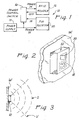
- Fig. 1 shows in block diagram form a low-power identification tag reader system generally designated by numeral.
- Reader system 10 includes a radio frequency tag reader 12 which may be any type of radio frequency reader, but for reasons given earlier herein, this invention is particularly useful with proximity or passive RFID tag readers because of their greater operating power consumption.
- the reader system 1 a is supplied with operating power by electrical power supply 14 connected to the reader 12 through a power control circuit or switch 16.
- Power supply 14 may be an A.C. line power supply but will normally be a battery power supply since a principal object of this invention is to enable practical battery operation of the reader system 10.
- the tag reader 12 has a radio frequency antenna 18, suggested in phantom lining in Fig. 2, which emits an interrogation signal designed to evoke a response from ID tags in sufficient proximity to the reader 12, and to receive a radio frequency response signal from any such ID tags.
- the antenna or antenna system of the tag reader 12 has a sensing field S, suggested by the concentric arcs in Fig. 3, within which the ID reader is capable of evoking a response from ID tags and also to receive the response signal from the tags. Outside of this sensing field, the strength of the interrogation signal may be insufficient to evoke a response, or if a response is evoked, the strength of the response signal at the antenna 18 is too weak to be read by the reader 12.
- the range of the tag reader 12 is limited in terms of distance from the antenna, but the range may also vary with direction from the antenna, i.e., the antenna may have a directional pattern with greatest sensitivity in a particular direction and diminishing sensitivity away from that direction.
- Directionality of the tag reader may be further determined not only by the antenna radiation pattern but also by the physical environment around the reader. If the reader system 10 is mounted on a wall W as in Fig. 3, then the effective sensing field S is limited to the area in front of that wall because ID tags will be present only in that area and not behind the wall, even though the tag reader's radio frequency field may in fact extend through and behind the wall. Consequently, the sensing field of the tag reader 12 is limited in range and direction by its radio frequency signal radiation and reception patterns and by the physical environment around the reader system 10 as in Fig.s 2 and 3.
- a secondary detector 20 is provided having a field of view V which generally overlaps the sensing field S of the RFID tag reader 12
- the presently preferred secondary detector 20 a passive infrared (PIR) motion detector of the type commonly used in home security systems for turning on lights in response to changes in the infrared background in the detector's field of view, such as a person's moving body in front of the PIR detector.
- PIR detectors of this type are now commercially available at low cost. In conventional applications the PIR detector derives an output signal which is typically used to trigger a security alarm or to switch lights.
- a PIR detector When implemented according to this invention as the secondary detector 20, a PIR detector is arranged and positioned as in Fig.s 2 and 3 relative to the RFID reader 12 so as to detect, for example, the presence of a hand waving an ID tag in front of the RFID tag reader 12.
- the output signal of the secondary detector is connected as an ON control signal to power control switching circuit 16.
- the power control switch 16 is turned off to inactivate the RFID reader 12.
- the resulting ON control signal of the secondary detector actuates power switch 16 for supplying electrical power to RFID reader 12 from power supply 14, thereby activating the RFID reader.
- the tag reader 12 operates in a conventional manner and transmits a radio frequency signal designed to evoke a radio-frequency response from any ID tags within range of the reader, and listens for any radio frequency response from the ID tags.
- the tag reader 12 will remain turned on only for the length of time necessary to read an ID tag.
- the reader If after an appropriate time no ID tag response is evoked by the reader's transmission, the reader outputs an OFF control signal to the power control switch, thereby shutting down power and returning the reader to a wait state. If the secondary detector in fact detected the entry of an ID tag into the sensing field S, the tag reader 12 then also executes an access control function to enable access to the protected facility, such as by opening an electric door lock and returning the facility to a locked condition. Upon completion of the access control cycle, the reader outputs the OFF control signal to the power control switch and is returned to a wait state.
- the tag reader 12 typically operates under control of a microprocessor, and the output of the OFF control signal at the appropriate time is accomplished by suitable programming of the microprocessor.
- the power control switch 16 may operate to suspend only some functions of the RFID reader rather than completely turning off power to the tag reader. It may be undesirable to entirely shut-down the tag reader 12 because certain initialization functions of the microprocessor would require re-execution upon every power-up. For this reason, the ON control signal may instead operate to invoke certain functions and subroutines of the microprocessor needed to actively sense and read ID tags, while keeping the microprocessor in a low power state in the wait state of the tag reader. That is, the wait state of the tag reader 12 is any state where power consumption of the tag reader is limited to less than its normal operating requirements for detecting and reading ID tags.
- the on-time of the RFID reader per ID tag may be quite short, of the order of a few seconds, depending on the type of access being controlled.
- the RFID reader duty cycle i.e. on-time of the RFID reader 12 relative to operating time of the reader system 10
- the combined reader 10 may be packaged for either portable or stationary use, in any housing that may suit practical and esthetic considerations.
- Passive IR detectors consume little power as compared to passive RFID detectors because the PIR detector does not emit a signal but rather responds to the presence of radiation emitted by a warm object or body.
- the choice of secondary detector is not limited to infrared detectors.
- Other motion sensing technologies are available which may be adapted for the purposes of this invention.
- inductive or capacitive type sensors may be implemented as the secondary detector 16 for detecting the entry of an object into the sensing field of the RFID reader by detecting changes in inductance or capacitance in the environment near the reader.
- ultrasound and microwave motion sensors are available and can be substituted for the passive infrared detector 16.
- a passive sensing technology such as inductive or capacitive will normally be preferred to an active technology such as microwave or ultrasound motion sensing because passive detectors typically consume less electrical power.
- multiple secondary detectors 16 may be installed and connected in OR logic so that the RFID reader is turned on if either of multiple secondary detectors is activated. Multiple secondary detectors may also be connected in AND fashion so that the RFID reader turns on only if both secondary detectors are activated to reduce false activations of the reader.
Abstract
Description
- This invention relates to radio-frequency identification readers used in conjunction with identification tags in controlled access systems, and more particularly is directed to low power proximity readers suitable for battery powered operation.
- Radio Frequency Identification Systems (RFID) have come into widespread usage and generally include a reader, typically installed in a fixed location, and a population of portable identification tags. Each ID tag contains a transponder unit which returns a coded response when interrogated by a radio-frequency transmission from the reader. The reader periodically sends out a transmission designed to evoke a radio-frequency response from any ID tags within range of the reader. The tag response includes coded identification data based on which the reader makes a decision to grant or deny access to controlled facilities. RFID systems may use active tags which carry their own source of power such as a battery, or passive tags which contain no source of power and instead rely entirely on energy radiated by the reader unit. Passive tag readers continually or periodically search for the presence of passive tags in the vicinity of the reader by transmitting energy which will activate any tag present. A passive tag does not announce its presence unless activated by the reader. Furthermore, the passive ID tag requires that it receive sufficient radio-frequency power which, when converted by the tag into the electrical current, will support operation of the tag's electronic circuits. Consequently, the operating range of the reader/tag system is to a large extent determined by the power transmitted by the reader, and the ID tag must come into sufficient proximity to the reader for the tag to be activated. For this reason passive tag readers are also know as proximity readers. Proximity readers typically have substantially greater operating power requirements than active tag RFID readers of comparable range, and the development of portable battery powered proximity readers has been hindered by excessive power drain on the batteries.
- A continuing need exists for RFID readers of reduced operating power requirements and, in particular, for a low power proximity reader which can be adequately powered by batteries for portable use.
- US-A-3 859 624 is acknowledged in the preamble of claim 1.
- The invention is set out in claims 1 and 7.
- The present invention addresses the aforementioned need by providing a low power radio-frequency identification reader system which includes a RFID tag reader operative for detecting and verifying the presence of identification tags present within a sensing field of the reader by evoking a radio-frequency response from the identification tags, and a secondary detector operative for detecting a change in the sensing field of the RFID tag reader indicative of the possible entry of an identification tag into the reader's sensing field and deriving an enabling signal responsive to such a change. By detecting such changes the secondary detector serves to detect the entry of an object into the sensing field but by means other than evoking a radio-frequency response from such an object.
- A power supply is provided for supplying operating power to the RFID tag reader and to the secondary detector. The detector and the reader each have an average, operating power requirement, and the secondary detector is selected to have a substantially smaller average operating power requirement than the reader. A power switching circuit normally limits or cuts off power from the power supply to the RFID tag reader while supplying the secondary detector. Full operating power to the RFID tag reader is enabled by the power switching circuit for a limited period of time in response to the enabling signal in order to verify the presence of an ID tag and, if so, to permit access to the controlled facilities. As a result, the RFID reader is relegated to a low duty cycle relative to the secondary detector and the overall or average operating power of the reader system is conserved by only operating the RFID tag reader briefly upon detection of a physical change such as movement in the readers sensing field indicative of the possible presence of an ID tag.
- Although the low power RFID tag reader system of this invention is not limited to any particular type of RFID reader, it will be found most useful with proximity or passive tag readers because of their relatively high operating power requirements. For this reason, in a preferred form of the invention, the RFID reader is a proximity reader designed to detect the presence of passive identification tags.
- The secondary detector is not limited to any particular sensing technology. Rather, the secondary detector should be chosen to draw little power as compared to the RFID reader so that a significant power savings can be realized by reducing the duty cycle of the RFID reader and relying instead on the secondary detector most of the time. The secondary detector may, for example and without limitation, be selected from the group comprised of passive infrared, inductive, capacitive, microwave and ultrasound detectors. Generally the secondary detector operates as a motion detector since the changes to which it responds are normally brought about by movement of objects which are not necessarily ID tags. A presently preferred secondary detector is a passive infrared sensor designed to sense changes in the infrared background in the reader's sensing field.
- Power savings may be optimized by limiting operation of the RFID reader to approximately the time period required to verify the presence of an ID tag, i.e., to transmit a radio-frequency interrogation signal, to receive and decode a response from an ID tag if present in the sensing field, and if an ID tag is detected, to execute an access control function such as unlocking a door and then locking it again. Upon completion of the tag read function or access control function, the tag reader outputs a disabling or off control signal to the power control switch for returning the tag reader to a power limited wait state.
- This invention also extends to a method of operating a radio-frequency identification tag reader having a sensing field, comprising the steps of placing the RFID reader in a wait state or sleep mode, detecting the introduction of an object into the sensing field, activating or waking the radio-frequency reader for a relatively short period of time at least sufficient for evoking a response from an identification tag if present in the sensing field; and returning the radio-frequency proximity reader to the wait state or sleep mode. The step of detecting may include sensing a change in a physical characteristic within the sensing field such as a change in position of an object not necessarily an ID tag within the sensing field of the RFID reader. The change in position may be made by infrared, inductive, capacitive, ultrasound or microwave sensing.
-
- Figure 1 is a block diagram of a low power consumption radio frequency identification system according to this invention;
- Figure 2 depicts a low-power RFID reader system according to this invention featuring a passive infrared secondary detector; and
- Figure 3 is a plan view diagram of the low-power RFID reader system of Figure 2 illustrating the RFID sensing field and overlapping passive infrared field of view.
- With reference to the accompanying drawing, Fig. 1 shows in block diagram form a low-power identification tag reader system generally designated by numeral.
Reader system 10 includes a radiofrequency tag reader 12 which may be any type of radio frequency reader, but for reasons given earlier herein, this invention is particularly useful with proximity or passive RFID tag readers because of their greater operating power consumption. The reader system 1 a is supplied with operating power byelectrical power supply 14 connected to thereader 12 through a power control circuit or switch 16.Power supply 14 may be an A.C. line power supply but will normally be a battery power supply since a principal object of this invention is to enable practical battery operation of thereader system 10. - The
tag reader 12 has a radio frequency antenna 18, suggested in phantom lining in Fig. 2, which emits an interrogation signal designed to evoke a response from ID tags in sufficient proximity to thereader 12, and to receive a radio frequency response signal from any such ID tags. The antenna or antenna system of thetag reader 12 has a sensing field S, suggested by the concentric arcs in Fig. 3, within which the ID reader is capable of evoking a response from ID tags and also to receive the response signal from the tags. Outside of this sensing field, the strength of the interrogation signal may be insufficient to evoke a response, or if a response is evoked, the strength of the response signal at the antenna 18 is too weak to be read by thereader 12. Not only is the range of thetag reader 12 limited in terms of distance from the antenna, but the range may also vary with direction from the antenna, i.e., the antenna may have a directional pattern with greatest sensitivity in a particular direction and diminishing sensitivity away from that direction. Directionality of the tag reader may be further determined not only by the antenna radiation pattern but also by the physical environment around the reader. If thereader system 10 is mounted on a wall W as in Fig. 3, then the effective sensing field S is limited to the area in front of that wall because ID tags will be present only in that area and not behind the wall, even though the tag reader's radio frequency field may in fact extend through and behind the wall. Consequently, the sensing field of thetag reader 12 is limited in range and direction by its radio frequency signal radiation and reception patterns and by the physical environment around thereader system 10 as in Fig.s 2 and 3. - According to this invention a
secondary detector 20 is provided having a field of view V which generally overlaps the sensing field S of the RFID tag reader 12The presently preferred secondary detector 20 a passive infrared (PIR) motion detector of the type commonly used in home security systems for turning on lights in response to changes in the infrared background in the detector's field of view, such as a person's moving body in front of the PIR detector. PIR detectors of this type are now commercially available at low cost. In conventional applications the PIR detector derives an output signal which is typically used to trigger a security alarm or to switch lights. - When implemented according to this invention as the
secondary detector 20, a PIR detector is arranged and positioned as in Fig.s 2 and 3 relative to theRFID reader 12 so as to detect, for example, the presence of a hand waving an ID tag in front of theRFID tag reader 12. The output signal of the secondary detector is connected as an ON control signal to powercontrol switching circuit 16. - In an initial wait state of the
tag reader 12 thepower control switch 16 is turned off to inactivate theRFID reader 12. When a moving object such as an ID tag holder's hand is detected by the PIRsecondary detector 20, the resulting ON control signal of the secondary detector actuatespower switch 16 for supplying electrical power toRFID reader 12 frompower supply 14, thereby activating the RFID reader. In its now active state thetag reader 12 operates in a conventional manner and transmits a radio frequency signal designed to evoke a radio-frequency response from any ID tags within range of the reader, and listens for any radio frequency response from the ID tags. Typically, thetag reader 12 will remain turned on only for the length of time necessary to read an ID tag. If after an appropriate time no ID tag response is evoked by the reader's transmission, the reader outputs an OFF control signal to the power control switch, thereby shutting down power and returning the reader to a wait state. If the secondary detector in fact detected the entry of an ID tag into the sensing field S, thetag reader 12 then also executes an access control function to enable access to the protected facility, such as by opening an electric door lock and returning the facility to a locked condition. Upon completion of the access control cycle, the reader outputs the OFF control signal to the power control switch and is returned to a wait state. Thetag reader 12 typically operates under control of a microprocessor, and the output of the OFF control signal at the appropriate time is accomplished by suitable programming of the microprocessor. - The
power control switch 16 may operate to suspend only some functions of the RFID reader rather than completely turning off power to the tag reader. It may be undesirable to entirely shut-down thetag reader 12 because certain initialization functions of the microprocessor would require re-execution upon every power-up. For this reason, the ON control signal may instead operate to invoke certain functions and subroutines of the microprocessor needed to actively sense and read ID tags, while keeping the microprocessor in a low power state in the wait state of the tag reader. That is, the wait state of thetag reader 12 is any state where power consumption of the tag reader is limited to less than its normal operating requirements for detecting and reading ID tags. - The on-time of the RFID reader per ID tag may be quite short, of the order of a few seconds, depending on the type of access being controlled. By limiting the on-time of the RFID reader in this fashion, the RFID reader duty cycle, i.e. on-time of the
RFID reader 12 relative to operating time of thereader system 10, can be made very small, thereby greatly reducing the power consumption of the combined RFID/PIR system 10 and making practical battery operation of such combined readers. The combinedreader 10 may be packaged for either portable or stationary use, in any housing that may suit practical and esthetic considerations. - Passive IR detectors consume little power as compared to passive RFID detectors because the PIR detector does not emit a signal but rather responds to the presence of radiation emitted by a warm object or body. However, the choice of secondary detector is not limited to infrared detectors. Other motion sensing technologies are available which may be adapted for the purposes of this invention. For example, inductive or capacitive type sensors may be implemented as the
secondary detector 16 for detecting the entry of an object into the sensing field of the RFID reader by detecting changes in inductance or capacitance in the environment near the reader. Similarly, ultrasound and microwave motion sensors are available and can be substituted for the passiveinfrared detector 16. Generally, a passive sensing technology such as inductive or capacitive will normally be preferred to an active technology such as microwave or ultrasound motion sensing because passive detectors typically consume less electrical power. For greater sensitivity and reliability, multiplesecondary detectors 16 may be installed and connected in OR logic so that the RFID reader is turned on if either of multiple secondary detectors is activated. Multiple secondary detectors may also be connected in AND fashion so that the RFID reader turns on only if both secondary detectors are activated to reduce false activations of the reader. - While a presently preferred embodiment of the invention has been described and illustrated for purposes of example and clarity it must be understood that many changes, substitutions and modifications to the described embodiment will be apparent to those having only ordinary skill in the art without thereby departing from the scope of the present invention as defined by the following claims.
Claims (9)
- A low-power radio-frequency proximity reader system comprising:a tag reader (12) operative for detecting identification tags by evoking a radio-frequency response from identification tags present within a sensing field of said reader;a secondary detector (20) operative as a motion detector for detecting entry of an object, including the waving of a hand in front of the tag reader, and including but not limited to entry of identification tags into said sensing field by means other than evoking a radio-frequency response from said object and for deriving an enabling control signal responsive to said detecting;power supply (14) means for supplying operating power to said tag reader and to said secondary detector, said detector and said tag reader each having an average operating power requirement, said detector selected to have a substantially smaller average operating power requirement than said tag reader; anda power control switch (16) characterized in that the power control switch (16) normally keeps said tag reader turned off, and is operative for activating said tag reader for transmitting radio frequency signals designed to evoke a radio frequency response from identification tags only for a limited period of time sufficient for detecting an identification tag if present in said sensing field in response to said enabling control signal;such that operating power is conserved by operating the tag reader only upon entry of the object into the tag reader's sensing field.
- The reader system of Claim 1 wherein said tag reader has a transmitter circuit and a receiver circuit connected to an antenna for transmitting a radio-frequency interrogation signal and decoding a response returned by identification tags within said sensing field of the tag reader.
- The reader system of Claim 1 wherein said secondary detector is a passive infrared detector.
- The reader system of Claim 1 wherein said secondary detector is selected from the group comprised of infrared, inductive, electrostatic, microwave and ultrasound detectors.
- The reader system of Claim 1 wherein said limited period of time is approximately the time period required to transmit a radio-frequency interrogation signal and receive and decode a response from an identification tag present in said sensing field, and executing an access control function by said tag reader.
- The reader system of Claim 1 wherein said tag reader provides an off control signal to said switch for returning said tag reader to a power limited state.
- A method of operating a radio-frequency proximity reader (12) having a sensing field, comprising:keeping said radio-frequency proximity reader in a wait state;detecting (20) motion within a field of view generally overlapping said sensing field of said tag reader; and characterized by;keeping said radio-frequency proximity reader in a wait state where said tag reader is disabled from making radio-frequency emissions;activating said radio-frequency reader in response to said motion for transmitting radio frequency signals only for a period of time generally sufficient for evoking a response from an identification tag if present in said sensing field; andreturning said radio-frequency proximity reader to said wait state.
- The method of Claim 7 wherein said step of detecting comprises sensing a change in a characteristic of said sensing field selected from a group comprised of infrared background, microwave reflectivity, ultrasound reflectivity, inductance and capacitance.
- The reader system of any of Claims 1 to 6 wherein the secondary detector (20) is operative for detecting motion within a field of view which generally overlaps the sensing field of the tag reader (12).
Applications Claiming Priority (3)
| Application Number | Priority Date | Filing Date | Title |
|---|---|---|---|
| US299121 | 1999-04-24 | ||
| US09/299,121 US6150948A (en) | 1999-04-24 | 1999-04-24 | Low-power radio frequency identification reader |
| PCT/US2000/010860 WO2000065551A1 (en) | 1999-04-24 | 2000-04-21 | Low-power radio frequency identification reader |
Publications (3)
| Publication Number | Publication Date |
|---|---|
| EP1185962A1 EP1185962A1 (en) | 2002-03-13 |
| EP1185962A4 EP1185962A4 (en) | 2004-07-28 |
| EP1185962B1 true EP1185962B1 (en) | 2007-04-11 |
Family
ID=23153391
Family Applications (1)
| Application Number | Title | Priority Date | Filing Date |
|---|---|---|---|
| EP00928301A Expired - Lifetime EP1185962B1 (en) | 1999-04-24 | 2000-04-21 | Low-power radio frequency identification reader |
Country Status (12)
| Country | Link |
|---|---|
| US (1) | US6150948A (en) |
| EP (1) | EP1185962B1 (en) |
| JP (1) | JP2002543646A (en) |
| CN (1) | CN1145128C (en) |
| AT (1) | ATE359577T1 (en) |
| AU (1) | AU761945B2 (en) |
| CA (1) | CA2370848C (en) |
| DE (1) | DE60034335T2 (en) |
| ES (1) | ES2284497T3 (en) |
| HK (1) | HK1044210B (en) |
| WO (1) | WO2000065551A1 (en) |
| ZA (1) | ZA200109462B (en) |
Families Citing this family (142)
| Publication number | Priority date | Publication date | Assignee | Title |
|---|---|---|---|---|
| US6369709B1 (en) | 1998-04-10 | 2002-04-09 | 3M Innovative Properties Company | Terminal for libraries and the like |
| CN100492388C (en) * | 1998-08-14 | 2009-05-27 | 3M创新有限公司 | Radio frequency identification system applications |
| AU762475B2 (en) | 1998-08-14 | 2003-06-26 | 3M Innovative Properties Company | Applications for radio frequency identification systems |
| US6839453B1 (en) * | 2000-05-16 | 2005-01-04 | The Upper Deck Company, Llc | Method and apparatus for authenticating unique items such as sports memorabilia |
| US6655591B1 (en) | 2000-09-22 | 2003-12-02 | Symbol Technologies, Inc. | Method and apparatus for reducing data collection device power consumption |
| US20020183882A1 (en) | 2000-10-20 | 2002-12-05 | Michael Dearing | RF point of sale and delivery method and system using communication with remote computer and having features to read a large number of RF tags |
| EP1419491A1 (en) * | 2001-08-23 | 2004-05-19 | Johnny Pollard | Fire detection system |
| US6758403B1 (en) | 2001-09-11 | 2004-07-06 | Psc Scanning, Inc. | System for editing data collection device message data |
| US6837427B2 (en) * | 2001-11-21 | 2005-01-04 | Goliath Solutions, Llc. | Advertising compliance monitoring system |
| US7374096B2 (en) | 2001-11-21 | 2008-05-20 | Goliath Solutions, Llc | Advertising compliance monitoring system |
| US6951305B2 (en) * | 2001-11-21 | 2005-10-04 | Goliath Solutions, Llc. | Advertising compliance monitoring system |
| US7139560B2 (en) * | 2001-12-19 | 2006-11-21 | Advanced Wireless Communications | Stimulus-dependent electronic device |
| EP1793326A3 (en) * | 2002-01-09 | 2008-06-11 | Vue Technology, Inc. | Intelligent station using multiple RF antennae and inventory control system and method incorporating same |
| DE10206676A1 (en) * | 2002-02-18 | 2003-08-28 | Giesecke & Devrient Gmbh | Switching device operable with a transponder |
| CN1309179C (en) * | 2002-04-17 | 2007-04-04 | 盛群半导体股份有限公司 | Recognition code transmission method and circuit arrangement |
| AU2003233113A1 (en) * | 2002-04-24 | 2003-11-10 | Marconi Intellectual Property (Us) Inc | Energy source recharging device and method |
| US20040106376A1 (en) * | 2002-04-24 | 2004-06-03 | Forster Ian J. | Rechargeable interrogation reader device and method |
| AU2003233007A1 (en) | 2002-04-24 | 2003-11-10 | Marconi Intellectual Property (Us) Inc | Energy source with a slot antenna formed in the body |
| EP2610872A3 (en) * | 2002-08-09 | 2013-07-24 | Panasonic Corporation | Mobile communication device, system comprising said device, and method of communication |
| US7239229B2 (en) * | 2002-09-05 | 2007-07-03 | Honeywell International Inc. | Efficient protocol for reading RFID tags |
| US20040046642A1 (en) * | 2002-09-05 | 2004-03-11 | Honeywell International Inc. | Protocol for addressing groups of RFID tags |
| US7573370B2 (en) * | 2002-09-05 | 2009-08-11 | Honeywell International Inc. | Method and device for storing and distributing information in an RFID tag |
| US6726099B2 (en) * | 2002-09-05 | 2004-04-27 | Honeywell International Inc. | RFID tag having multiple transceivers |
| US7044387B2 (en) * | 2002-09-05 | 2006-05-16 | Honeywell International Inc. | RFID tag and communication protocol for long range tag communications and power efficiency |
| CA2495686A1 (en) | 2002-09-27 | 2004-04-15 | Hill-Rom Services, Inc. | Universal communications, monitoring, tracking, and control system for a healthcare facility |
| US7283048B2 (en) | 2003-02-03 | 2007-10-16 | Ingrid, Inc. | Multi-level meshed security network |
| US7091827B2 (en) | 2003-02-03 | 2006-08-15 | Ingrid, Inc. | Communications control in a security system |
| US7057512B2 (en) * | 2003-02-03 | 2006-06-06 | Ingrid, Inc. | RFID reader for a security system |
| US7079020B2 (en) | 2003-02-03 | 2006-07-18 | Ingrid, Inc. | Multi-controller security network |
| US7532114B2 (en) | 2003-02-03 | 2009-05-12 | Ingrid, Inc. | Fixed part-portable part communications network for a security network |
| US7042353B2 (en) | 2003-02-03 | 2006-05-09 | Ingrid, Inc. | Cordless telephone system |
| US7079034B2 (en) | 2003-02-03 | 2006-07-18 | Ingrid, Inc. | RFID transponder for a security system |
| US7119658B2 (en) | 2003-02-03 | 2006-10-10 | Ingrid, Inc. | Device enrollment in a security system |
| US7019639B2 (en) | 2003-02-03 | 2006-03-28 | Ingrid, Inc. | RFID based security network |
| US7495544B2 (en) | 2003-02-03 | 2009-02-24 | Ingrid, Inc. | Component diversity in a RFID security network |
| US7053764B2 (en) * | 2003-02-03 | 2006-05-30 | Ingrid, Inc. | Controller for a security system |
| US7511614B2 (en) | 2003-02-03 | 2009-03-31 | Ingrid, Inc. | Portable telephone in a security network |
| US6888459B2 (en) * | 2003-02-03 | 2005-05-03 | Louis A. Stilp | RFID based security system |
| US7023341B2 (en) | 2003-02-03 | 2006-04-04 | Ingrid, Inc. | RFID reader for a security network |
| US20040215750A1 (en) * | 2003-04-28 | 2004-10-28 | Stilp Louis A. | Configuration program for a security system |
| US20040222876A1 (en) * | 2003-05-08 | 2004-11-11 | Hui-Hua Hsieh | Power-saving electric circuit for a remote-controlled lock |
| US7710852B2 (en) | 2003-05-30 | 2010-05-04 | Panasonic Corporation | Optical disc |
| GB0322694D0 (en) * | 2003-09-27 | 2003-10-29 | Hewlett Packard Development Co | A memory tag and a reader |
| US7145437B2 (en) * | 2003-10-16 | 2006-12-05 | Nokia Corporation | Method, terminal and computer program product for adjusting power consumption of a RFID reader associated with a mobile terminal |
| US20060108421A1 (en) * | 2003-12-03 | 2006-05-25 | Becker Robert C | RFID tag having multiple transceivers |
| US7362258B2 (en) * | 2004-03-31 | 2008-04-22 | Honda Motor Co., Ltd. | Transponder detection system using radio and light wave signals |
| US7499985B2 (en) * | 2004-06-22 | 2009-03-03 | Nokia Corporation | Intuitive energy management of a short-range communication transceiver associated with a mobile terminal |
| US7330117B2 (en) * | 2004-08-25 | 2008-02-12 | Caterpillar Inc. | Systems and methods for radio frequency trigger |
| US9020430B2 (en) | 2004-10-12 | 2015-04-28 | Nokia Corporation | Methods, apparatus, systems and computer program products for energy management of short-range communication modules in mobile terminal devices |
| US7551081B2 (en) | 2004-11-10 | 2009-06-23 | Rockwell Automation Technologies, Inc. | Systems and methods that integrate radio frequency identification (RFID) technology with agent-based control systems |
| US7339476B2 (en) | 2004-11-10 | 2008-03-04 | Rockwell Automation Technologies, Inc. | Systems and methods that integrate radio frequency identification (RFID) technology with industrial controllers |
| AU2005307755B2 (en) * | 2004-11-15 | 2009-10-01 | Sensormatic Electronics Llc | Combination EAS and RFID label or tag with controllable read range |
| DE102004057266A1 (en) * | 2004-11-26 | 2006-06-08 | Giesecke & Devrient Gmbh | communication device |
| JP4519142B2 (en) | 2005-01-13 | 2010-08-04 | 富士通株式会社 | Information access system and method for accessing information in a contactless information storage device |
| FR2880746A1 (en) * | 2005-01-13 | 2006-07-14 | Spirtech Sarl | Reader for application e.g. electronic payment, has detection unit measuring electric parameter, of magnetic field transmitters, to be modified by consecutive reactive effect with presence of magnetic coupling units of portable object |
| US20060176152A1 (en) * | 2005-02-10 | 2006-08-10 | Psc Scanning, Inc. | RFID power ramping for tag singulation |
| US20060192653A1 (en) * | 2005-02-18 | 2006-08-31 | Paul Atkinson | Device and method for selectively controlling the utility of an integrated circuit device |
| US7515051B2 (en) | 2005-02-25 | 2009-04-07 | Datalogic Mobile, Inc. | RFID antenna system having reduced orientation sensitivity |
| US20060208893A1 (en) * | 2005-02-28 | 2006-09-21 | Anson Gary S | Weight audit methods and systems utilizing data reader |
| US7786844B2 (en) * | 2005-03-01 | 2010-08-31 | I.D. Systems, Inc. | Mobile portal for RFID applications |
| US20060197652A1 (en) * | 2005-03-04 | 2006-09-07 | International Business Machines Corporation | Method and system for proximity tracking-based adaptive power control of radio frequency identification (RFID) interrogators |
| US7720438B2 (en) * | 2005-03-30 | 2010-05-18 | Nokia Corporation | Reducing power consumption of a short-range wireless communication reader associated with a mobile terminal |
| WO2006116528A2 (en) * | 2005-04-26 | 2006-11-02 | Rf Code, Inc. | Rfid systems and methods employing infrared localization |
| EP2275963B1 (en) * | 2005-05-12 | 2012-10-31 | Swisscom AG | Method, RFID tag and system for transmission of RFID identification data |
| US7636044B1 (en) | 2005-05-13 | 2009-12-22 | Rockwell Automation Technologies, Inc. | RFID tag programming, printing application, and supply chain/global registration architecture |
| US20060255943A1 (en) * | 2005-05-16 | 2006-11-16 | Psc Scanning, Inc. | Induction charging machine, methods, and system for a data reader |
| US20060267733A1 (en) * | 2005-05-27 | 2006-11-30 | Psc Scanning, Inc. | Apparatus and methods for saving power in RFID readers |
| US20060267731A1 (en) * | 2005-05-31 | 2006-11-30 | Chen Thomas C H | System and apparatus of Internet-linked RFID sensor network for object identifying, sensing, monitoring, tracking and networking |
| US7616117B2 (en) | 2005-07-19 | 2009-11-10 | Rockwell Automation Technologies, Inc. | Reconciliation mechanism using RFID and sensors |
| US7388491B2 (en) | 2005-07-20 | 2008-06-17 | Rockwell Automation Technologies, Inc. | Mobile RFID reader with integrated location awareness for material tracking and management |
| US7764191B2 (en) | 2005-07-26 | 2010-07-27 | Rockwell Automation Technologies, Inc. | RFID tag data affecting automation controller with internal database |
| US8260948B2 (en) * | 2005-08-10 | 2012-09-04 | Rockwell Automation Technologies, Inc. | Enhanced controller utilizing RFID technology |
| US7510110B2 (en) | 2005-09-08 | 2009-03-31 | Rockwell Automation Technologies, Inc. | RFID architecture in an industrial controller environment |
| DE102005044438A1 (en) * | 2005-09-16 | 2007-03-22 | Giesecke & Devrient Gmbh | With a transponder operable switching device |
| US7931197B2 (en) | 2005-09-20 | 2011-04-26 | Rockwell Automation Technologies, Inc. | RFID-based product manufacturing and lifecycle management |
| US7446662B1 (en) | 2005-09-26 | 2008-11-04 | Rockwell Automation Technologies, Inc. | Intelligent RFID tag for magnetic field mapping |
| JP4155408B2 (en) * | 2005-09-29 | 2008-09-24 | ソニー・エリクソン・モバイルコミュニケーションズ株式会社 | Charging device and charging system |
| US8025227B2 (en) | 2005-09-30 | 2011-09-27 | Rockwell Automation Technologies, Inc. | Access to distributed databases via pointer stored in RFID tag |
| US20070096909A1 (en) * | 2005-10-28 | 2007-05-03 | Matthew Lally | Interactive networking device |
| US7599427B2 (en) * | 2005-12-30 | 2009-10-06 | Honeywell International Inc. | Micro range radio frequency (RF) communications link |
| US7664461B2 (en) * | 2006-03-02 | 2010-02-16 | Broadcom Corporation | RFID reader architecture |
| US7532908B2 (en) * | 2006-03-02 | 2009-05-12 | Broadcom Corporation | Transceiver and method for combining RFID amplitude-modulated data with wireless phase-modulated data |
| US7477917B2 (en) * | 2006-03-02 | 2009-01-13 | Broadcom Corporation | RFID reader integrated with wireless communication device |
| US20070205865A1 (en) * | 2006-03-02 | 2007-09-06 | Broadcom Corporation, A California Corporation | Wireless communication device with RFID reader |
| FR2898201B1 (en) * | 2006-03-06 | 2008-05-16 | Cedom Sa | DEVICE FOR RECOGNITION AND SECURITY CONSISTING OF AT LEAST ONE BADGE AND A BADGE READER. |
| US7310070B1 (en) | 2006-08-23 | 2007-12-18 | Goliath Solutions, Llc | Radio frequency identification shelf antenna with a distributed pattern for localized tag detection |
| US7821400B2 (en) * | 2006-09-29 | 2010-10-26 | Datalogic Scanning, Inc. | System and method for verifying number of wireless tagged items in a transaction |
| US8199004B1 (en) * | 2006-09-29 | 2012-06-12 | Ncr Corporation | RFID tag reader |
| GB2443234B8 (en) * | 2006-10-24 | 2009-01-28 | Innovision Res & Tech Plc | Near field RF communicators and near field RF communications enabled devices |
| US7551092B1 (en) | 2006-11-15 | 2009-06-23 | Henry Kevin M | Sanitary monitoring system to monitor the hand sanitation of health care workers or other required sanitary activities |
| WO2008069626A1 (en) * | 2006-12-08 | 2008-06-12 | Electronics And Telecommunications Research Institute | Apparatus and method of generating wake-up signal in battery-powered passive tag |
| JP5001670B2 (en) * | 2007-02-09 | 2012-08-15 | 富士通株式会社 | Reader / writer output value automatic adjustment method |
| DE502007000937D1 (en) * | 2007-03-19 | 2009-08-06 | Simonsvoss Technologies Ag | Read unit and method for low-energy detection of a transponder |
| US7825806B2 (en) * | 2007-09-25 | 2010-11-02 | Symbol Technologies, Inc. | Optimizing RFID reader duty cycle or power to preserve battery life |
| US7652578B2 (en) * | 2007-10-29 | 2010-01-26 | Motorola, Inc. | Detection apparatus and method for near field communication devices |
| EP2058750A1 (en) * | 2007-11-09 | 2009-05-13 | Unified Packet Systems Corp. | Microwave control system |
| US8167203B2 (en) * | 2007-12-18 | 2012-05-01 | Utc Fire & Security Americas Corporation, Inc. | Credential reader having a micro power proximity detector and method of operating the credential reader |
| JP2008182717A (en) * | 2008-02-04 | 2008-08-07 | Toshiba Tec Corp | Radio tag reader |
| US7859404B2 (en) | 2008-03-25 | 2010-12-28 | Tyco Safety Products Canada Ltd. | Method and apparatus for proximity activated RFID system |
| CN101276403B (en) * | 2008-04-10 | 2010-06-02 | 珠海信石电子科技有限公司 | ID identification apparatus and identification method as well as using method |
| US8965461B2 (en) * | 2008-05-13 | 2015-02-24 | Qualcomm Incorporated | Reverse link signaling via receive antenna impedance modulation |
| US8223014B2 (en) * | 2008-07-02 | 2012-07-17 | Essence Security International Ltd. | Energy-conserving triggered ID system and method |
| JP4552158B2 (en) * | 2008-07-09 | 2010-09-29 | ソニー株式会社 | Communication device |
| US8558660B2 (en) * | 2008-11-19 | 2013-10-15 | Proventix Systems, Inc. | Method and apparatus for detecting and identifying device utilization |
| US9147334B2 (en) | 2008-11-19 | 2015-09-29 | Proventix Systems, Inc. | System and method for monitoring hospital workflow compliance with a hand hygiene network |
| US20100182153A1 (en) * | 2008-11-25 | 2010-07-22 | Kurt Holdgaard Jensen | Apparatus with an infrared sensor and magnetic near field communication properties for monitoring activity in a selected area |
| WO2010112020A1 (en) * | 2009-03-31 | 2010-10-07 | Hw Verwaltungs Gmbh | System for logistical monitoring and control of the flow of goods, the storage thereof, storage and transport conditions, and consumption |
| FR2946169B1 (en) * | 2009-05-28 | 2013-07-05 | Ingenico Sa | ACTIVATION OF A NON-CONTACT DEVICE BY A CAPACITIVE DEVICE |
| CN101783032B (en) * | 2009-12-28 | 2014-07-16 | 上海搜林信息技术有限公司 | Electronic vehicle toll collection system and toll collection method thereof |
| DE102010020376A1 (en) * | 2010-05-12 | 2011-11-17 | Siemens Aktiengesellschaft | Device for reading radio tags or RFIDs and corresponding use of this device |
| DE102010029996B4 (en) | 2010-06-11 | 2021-08-05 | Brooks Automation (Germany) Gmbh | Inventory monitoring of flow warehouses using RFID |
| US8681005B2 (en) * | 2010-09-28 | 2014-03-25 | Symbol Technologies, Inc. | RFID reader with motion detection |
| EP2469478A1 (en) * | 2010-12-21 | 2012-06-27 | 9Solutions Oy | Access control in location tracking system |
| US8762704B2 (en) * | 2011-09-29 | 2014-06-24 | Apple Inc. | Customized content for electronic devices |
| KR101503966B1 (en) * | 2011-10-28 | 2015-03-25 | 삼성전기주식회사 | Wireless communication terminal with rf direct wakeup, and wakeup method of the same |
| TWI502887B (en) * | 2012-09-27 | 2015-10-01 | Hon Hai Prec Ind Co Ltd | Power source control device and control method |
| EP2912637B1 (en) | 2012-10-23 | 2021-12-08 | Spectrum Brands, Inc. | Electronic lock having software based automatic multi-wireless profile detection and setting |
| EP2912638B1 (en) | 2012-10-26 | 2020-06-17 | Spectrum Brands, Inc. | Method of updating one or more lock settings of an electronic lock using a mobile device |
| US10240365B2 (en) | 2012-12-12 | 2019-03-26 | Spectrum Brands, Inc. | Electronic lock system having proximity mobile device |
| CN104077551B (en) * | 2013-03-29 | 2017-10-24 | 西门子公司 | A kind of recognition methods of RFID tag, device and system |
| FR3004830B1 (en) * | 2013-04-22 | 2016-09-02 | Eff'innov Tech | DEVICE FOR READING WIRELESS CARDS |
| US9830424B2 (en) | 2013-09-18 | 2017-11-28 | Hill-Rom Services, Inc. | Bed/room/patient association systems and methods |
| US20150179053A1 (en) * | 2013-12-20 | 2015-06-25 | General Electric Company | System and method to detect a presence of an object relative to a support |
| GB201402314D0 (en) * | 2014-02-11 | 2014-03-26 | Camlock Systems Ltd | Locking apparatus |
| EP2927838B1 (en) | 2014-04-02 | 2016-03-16 | Sick Ag | System and method for identifying and locating objects |
| CN105447351A (en) * | 2014-08-21 | 2016-03-30 | 联想(北京)有限公司 | Control method and apparatus |
| DE102015015036A1 (en) * | 2015-11-23 | 2017-05-24 | race result AG | Position tracking at sports events |
| FR3051283B1 (en) * | 2016-05-12 | 2018-04-27 | Dura Operating, Llc | ELECTRO MAGNETIC COUPLING READER |
| US9959439B1 (en) * | 2016-06-23 | 2018-05-01 | Amazon Technologies, Inc. | Activating a radio frequency identification (RFID) reader to read an RFID tag |
| US20180096291A1 (en) * | 2016-10-05 | 2018-04-05 | Avery Dennison Retail Information Services, Llc | Method, system, and apparatus for promotional display and information gathering |
| US10376186B2 (en) | 2016-10-18 | 2019-08-13 | International Business Machines Corporation | Thermal tags for real-time activity monitoring and methods for fabricating the same |
| US10395071B2 (en) | 2016-12-01 | 2019-08-27 | Avery Dennison Retail Information Services, Llc | Control of RFID reader emissions which may cause interference with systems using RFID tags |
| US10794987B2 (en) * | 2016-12-05 | 2020-10-06 | Centrak, Inc. | Hybrid IR-US RTLS system |
| US10609526B2 (en) * | 2017-01-11 | 2020-03-31 | Centrak, Inc. | Real-time location system, device and methods |
| EP3373190B1 (en) * | 2017-03-10 | 2021-08-18 | Sony Group Corporation | Electronic tag |
| CN110546689A (en) * | 2017-03-15 | 2019-12-06 | 香港物流及供应链管理应用技术研发中心 | System and method for access control |
| ES2659420A1 (en) * | 2017-07-26 | 2018-03-15 | Universitat Politècnica De València | Tile and mesh for the identification and monitoring of animals and animal identification and tracking system (Machine-translation by Google Translate, not legally binding) |
| US20190122196A1 (en) * | 2017-10-24 | 2019-04-25 | Symbol Technologies, Llc | Systems and methods of operating a point of sale system |
| US10783731B2 (en) | 2018-04-27 | 2020-09-22 | Spectrum Brands, Inc. | Wireless tag-based lock actuation systems and methods |
| US20210319392A1 (en) * | 2018-08-27 | 2021-10-14 | Pravin Chhatrapati PATIL | Product re-ordering notification device |
| US11911325B2 (en) | 2019-02-26 | 2024-02-27 | Hill-Rom Services, Inc. | Bed interface for manual location |
| TW202329055A (en) * | 2022-01-06 | 2023-07-16 | 群光電子股份有限公司 | Waking device and method for waking an electronic device |
Family Cites Families (10)
| Publication number | Priority date | Publication date | Assignee | Title |
|---|---|---|---|---|
| US3859624A (en) * | 1972-09-05 | 1975-01-07 | Thomas A Kriofsky | Inductively coupled transmitter-responder arrangement |
| US4240064A (en) * | 1978-09-11 | 1980-12-16 | Ncr Corporation | Power limiting circuit for bar code reader |
| DE3623792C1 (en) * | 1986-07-15 | 1987-12-10 | Messerschmitt Boelkow Blohm | Device for determining the number of people and direction within a room to be monitored or a passage gate |
| JPH0766804A (en) * | 1993-08-27 | 1995-03-10 | Smk Corp | Security system |
| JPH07220123A (en) * | 1994-02-04 | 1995-08-18 | Omron Corp | Non-contact ticket checking machine |
| JP3170425B2 (en) * | 1994-03-24 | 2001-05-28 | 株式会社クボタ | Monitoring device |
| US6040773A (en) * | 1995-10-11 | 2000-03-21 | Motorola, Inc. | Radio frequency identification tag arranged for magnetically storing tag state information |
| US5682032A (en) * | 1996-02-22 | 1997-10-28 | Philipp; Harald | Capacitively coupled identity verification and escort memory apparatus |
| JPH09305810A (en) * | 1996-05-15 | 1997-11-28 | Shinko Electric Co Ltd | Unwanted power transmission suppressing method and radio type card system applying the same |
| US6476708B1 (en) * | 1998-03-20 | 2002-11-05 | Hid Corporation | Detection of an RFID device by an RF reader unit operating in a reduced power state |
-
1999
- 1999-04-24 US US09/299,121 patent/US6150948A/en not_active Expired - Lifetime
-
2000
- 2000-04-21 AU AU46559/00A patent/AU761945B2/en not_active Ceased
- 2000-04-21 DE DE60034335T patent/DE60034335T2/en not_active Expired - Fee Related
- 2000-04-21 CN CNB008093318A patent/CN1145128C/en not_active Expired - Fee Related
- 2000-04-21 ES ES00928301T patent/ES2284497T3/en not_active Expired - Lifetime
- 2000-04-21 JP JP2000614220A patent/JP2002543646A/en active Pending
- 2000-04-21 CA CA002370848A patent/CA2370848C/en not_active Expired - Fee Related
- 2000-04-21 AT AT00928301T patent/ATE359577T1/en not_active IP Right Cessation
- 2000-04-21 WO PCT/US2000/010860 patent/WO2000065551A1/en active Search and Examination
- 2000-04-21 EP EP00928301A patent/EP1185962B1/en not_active Expired - Lifetime
-
2001
- 2001-11-16 ZA ZA200109462A patent/ZA200109462B/en unknown
-
2002
- 2002-08-06 HK HK02105753.4A patent/HK1044210B/en not_active IP Right Cessation
Non-Patent Citations (1)
| Title |
|---|
| None * |
Also Published As
| Publication number | Publication date |
|---|---|
| CA2370848C (en) | 2008-01-15 |
| ES2284497T3 (en) | 2007-11-16 |
| CA2370848A1 (en) | 2000-11-02 |
| DE60034335D1 (en) | 2007-05-24 |
| JP2002543646A (en) | 2002-12-17 |
| AU761945B2 (en) | 2003-06-12 |
| ZA200109462B (en) | 2002-08-16 |
| DE60034335T2 (en) | 2007-12-27 |
| CN1391686A (en) | 2003-01-15 |
| EP1185962A4 (en) | 2004-07-28 |
| AU4655900A (en) | 2000-11-10 |
| WO2000065551A1 (en) | 2000-11-02 |
| EP1185962A1 (en) | 2002-03-13 |
| HK1044210A1 (en) | 2002-10-11 |
| ATE359577T1 (en) | 2007-05-15 |
| CN1145128C (en) | 2004-04-07 |
| HK1044210B (en) | 2007-06-15 |
| US6150948A (en) | 2000-11-21 |
Similar Documents
| Publication | Publication Date | Title |
|---|---|---|
| EP1185962B1 (en) | Low-power radio frequency identification reader | |
| JP2002543646A5 (en) | ||
| KR100920317B1 (en) | Passive communication device and passive access control system | |
| JP4300470B2 (en) | Object detection device and control device | |
| US8258957B2 (en) | Methods and apparatus for switching a transponder to an active state, and asset management systems employing same | |
| EP1048807B1 (en) | System for automatic vehicle unlock initiated via beam interruption | |
| US20130099893A1 (en) | Lock control system using rfid | |
| CN105934152A (en) | Access control for animals using electronic recognition | |
| KR101405892B1 (en) | Apparatus and Method for Controlling Going In and Out Using ZigBee Communication | |
| US8558664B2 (en) | Passive approach detection system and method using a unidirectional FOB | |
| JP2007132119A (en) | Communication equipment for vehicle | |
| JP2001032584A (en) | Locking and unlocking controller making use of non- contact ic card | |
| EP2310978B1 (en) | Energy-conserving triggered id system | |
| KR20060005827A (en) | Rfid system for locating and tracking a moving object and communication method of between rf tag and reader | |
| GB2277850A (en) | Intelligent radio frequency transponder system | |
| JPH08167014A (en) | Radio ic card, charge reception system using the ic card and power supply control method of radio ic card | |
| KR20150006560A (en) | Battery Lifetime Increasing Method by Using Drease of Power Consumpution of Difital Door Lock and Digital Door lock System thereof | |
| KR100540890B1 (en) | Contactless IC Card Reader of Contactless IC Card System | |
| KR20040036117A (en) | Apparatus and method for preventing data contact between contactless ic card reader and contactless ic cards | |
| JPH09319979A (en) | Moving body management device | |
| KR20060000836A (en) | Remote control unit for touchless door lock system and the communication method thereby | |
| JP2006214835A (en) | Wireless tag communication system |
Legal Events
| Date | Code | Title | Description |
|---|---|---|---|
| PUAI | Public reference made under article 153(3) epc to a published international application that has entered the european phase |
Free format text: ORIGINAL CODE: 0009012 |
|
| 17P | Request for examination filed |
Effective date: 20011025 |
|
| AK | Designated contracting states |
Kind code of ref document: A1 Designated state(s): AT BE CH CY DE DK ES FI FR GB GR IE IT LI LU MC NL PT SE |
|
| AX | Request for extension of the european patent |
Free format text: AL;LT;LV;MK;RO;SI |
|
| A4 | Supplementary search report drawn up and despatched |
Effective date: 20040611 |
|
| RIC1 | Information provided on ipc code assigned before grant |
Ipc: 7G 08B 23/00 A Ipc: 7G 06K 7/00 B |
|
| 17Q | First examination report despatched |
Effective date: 20050131 |
|
| GRAP | Despatch of communication of intention to grant a patent |
Free format text: ORIGINAL CODE: EPIDOSNIGR1 |
|
| GRAS | Grant fee paid |
Free format text: ORIGINAL CODE: EPIDOSNIGR3 |
|
| GRAA | (expected) grant |
Free format text: ORIGINAL CODE: 0009210 |
|
| AK | Designated contracting states |
Kind code of ref document: B1 Designated state(s): AT BE CH CY DE DK ES FI FR GB GR IE IT LI LU MC NL PT SE |
|
| PG25 | Lapsed in a contracting state [announced via postgrant information from national office to epo] |
Ref country code: LI Free format text: LAPSE BECAUSE OF FAILURE TO SUBMIT A TRANSLATION OF THE DESCRIPTION OR TO PAY THE FEE WITHIN THE PRESCRIBED TIME-LIMIT Effective date: 20070411 Ref country code: FI Free format text: LAPSE BECAUSE OF FAILURE TO SUBMIT A TRANSLATION OF THE DESCRIPTION OR TO PAY THE FEE WITHIN THE PRESCRIBED TIME-LIMIT Effective date: 20070411 Ref country code: CH Free format text: LAPSE BECAUSE OF FAILURE TO SUBMIT A TRANSLATION OF THE DESCRIPTION OR TO PAY THE FEE WITHIN THE PRESCRIBED TIME-LIMIT Effective date: 20070411 |
|
| REG | Reference to a national code |
Ref country code: GB Ref legal event code: FG4D |
|
| PGFP | Annual fee paid to national office [announced via postgrant information from national office to epo] |
Ref country code: NL Payment date: 20070417 Year of fee payment: 8 |
|
| PGFP | Annual fee paid to national office [announced via postgrant information from national office to epo] |
Ref country code: DE Payment date: 20070418 Year of fee payment: 8 |
|
| PGFP | Annual fee paid to national office [announced via postgrant information from national office to epo] |
Ref country code: ES Payment date: 20070426 Year of fee payment: 8 Ref country code: SE Payment date: 20070426 Year of fee payment: 8 |
|
| REG | Reference to a national code |
Ref country code: CH Ref legal event code: EP |
|
| REG | Reference to a national code |
Ref country code: IE Ref legal event code: FG4D |
|
| REF | Corresponds to: |
Ref document number: 60034335 Country of ref document: DE Date of ref document: 20070524 Kind code of ref document: P |
|
| REG | Reference to a national code |
Ref country code: HK Ref legal event code: GR Ref document number: 1044210 Country of ref document: HK |
|
| REG | Reference to a national code |
Ref country code: SE Ref legal event code: TRGR |
|
| PG25 | Lapsed in a contracting state [announced via postgrant information from national office to epo] |
Ref country code: PT Free format text: LAPSE BECAUSE OF FAILURE TO SUBMIT A TRANSLATION OF THE DESCRIPTION OR TO PAY THE FEE WITHIN THE PRESCRIBED TIME-LIMIT Effective date: 20070911 |
|
| ET | Fr: translation filed | ||
| REG | Reference to a national code |
Ref country code: CH Ref legal event code: PL |
|
| REG | Reference to a national code |
Ref country code: ES Ref legal event code: FG2A Ref document number: 2284497 Country of ref document: ES Kind code of ref document: T3 |
|
| PG25 | Lapsed in a contracting state [announced via postgrant information from national office to epo] |
Ref country code: AT Free format text: LAPSE BECAUSE OF FAILURE TO SUBMIT A TRANSLATION OF THE DESCRIPTION OR TO PAY THE FEE WITHIN THE PRESCRIBED TIME-LIMIT Effective date: 20070411 |
|
| PGFP | Annual fee paid to national office [announced via postgrant information from national office to epo] |
Ref country code: GB Payment date: 20070501 Year of fee payment: 8 |
|
| PGFP | Annual fee paid to national office [announced via postgrant information from national office to epo] |
Ref country code: BE Payment date: 20070406 Year of fee payment: 8 Ref country code: IT Payment date: 20070613 Year of fee payment: 8 |
|
| PLBI | Opposition filed |
Free format text: ORIGINAL CODE: 0009260 |
|
| PG25 | Lapsed in a contracting state [announced via postgrant information from national office to epo] |
Ref country code: DK Free format text: LAPSE BECAUSE OF FAILURE TO SUBMIT A TRANSLATION OF THE DESCRIPTION OR TO PAY THE FEE WITHIN THE PRESCRIBED TIME-LIMIT Effective date: 20070411 |
|
| PLAX | Notice of opposition and request to file observation + time limit sent |
Free format text: ORIGINAL CODE: EPIDOSNOBS2 |
|
| 26 | Opposition filed |
Opponent name: KAZI, ILYA Effective date: 20080110 |
|
| NLR1 | Nl: opposition has been filed with the epo |
Opponent name: KAZI, ILYA |
|
| PG25 | Lapsed in a contracting state [announced via postgrant information from national office to epo] |
Ref country code: GR Free format text: LAPSE BECAUSE OF FAILURE TO SUBMIT A TRANSLATION OF THE DESCRIPTION OR TO PAY THE FEE WITHIN THE PRESCRIBED TIME-LIMIT Effective date: 20070712 |
|
| PGFP | Annual fee paid to national office [announced via postgrant information from national office to epo] |
Ref country code: FR Payment date: 20070425 Year of fee payment: 8 |
|
| PLAF | Information modified related to communication of a notice of opposition and request to file observations + time limit |
Free format text: ORIGINAL CODE: EPIDOSCOBS2 |
|
| BERE | Be: lapsed |
Owner name: SOUNDCRAFT, INC. Effective date: 20080430 |
|
| EUG | Se: european patent has lapsed | ||
| GBPC | Gb: european patent ceased through non-payment of renewal fee |
Effective date: 20080421 |
|
| NLV4 | Nl: lapsed or anulled due to non-payment of the annual fee |
Effective date: 20081101 |
|
| PG25 | Lapsed in a contracting state [announced via postgrant information from national office to epo] |
Ref country code: NL Free format text: LAPSE BECAUSE OF NON-PAYMENT OF DUE FEES Effective date: 20081101 Ref country code: DE Free format text: LAPSE BECAUSE OF NON-PAYMENT OF DUE FEES Effective date: 20081101 |
|
| REG | Reference to a national code |
Ref country code: FR Ref legal event code: ST Effective date: 20081231 |
|
| PG25 | Lapsed in a contracting state [announced via postgrant information from national office to epo] |
Ref country code: BE Free format text: LAPSE BECAUSE OF NON-PAYMENT OF DUE FEES Effective date: 20080430 Ref country code: MC Free format text: LAPSE BECAUSE OF NON-PAYMENT OF DUE FEES Effective date: 20070430 |
|
| PG25 | Lapsed in a contracting state [announced via postgrant information from national office to epo] |
Ref country code: IE Free format text: LAPSE BECAUSE OF NON-PAYMENT OF DUE FEES Effective date: 20080421 Ref country code: FR Free format text: LAPSE BECAUSE OF NON-PAYMENT OF DUE FEES Effective date: 20080430 |
|
| REG | Reference to a national code |
Ref country code: ES Ref legal event code: FD2A Effective date: 20080422 |
|
| PG25 | Lapsed in a contracting state [announced via postgrant information from national office to epo] |
Ref country code: GB Free format text: LAPSE BECAUSE OF NON-PAYMENT OF DUE FEES Effective date: 20080421 |
|
| PG25 | Lapsed in a contracting state [announced via postgrant information from national office to epo] |
Ref country code: CY Free format text: LAPSE BECAUSE OF FAILURE TO SUBMIT A TRANSLATION OF THE DESCRIPTION OR TO PAY THE FEE WITHIN THE PRESCRIBED TIME-LIMIT Effective date: 20070411 Ref country code: ES Free format text: LAPSE BECAUSE OF NON-PAYMENT OF DUE FEES Effective date: 20080422 |
|
| PG25 | Lapsed in a contracting state [announced via postgrant information from national office to epo] |
Ref country code: IT Free format text: LAPSE BECAUSE OF NON-PAYMENT OF DUE FEES Effective date: 20080421 Ref country code: LU Free format text: LAPSE BECAUSE OF NON-PAYMENT OF DUE FEES Effective date: 20070421 |
|
| PGFP | Annual fee paid to national office [announced via postgrant information from national office to epo] |
Ref country code: IE Payment date: 20071018 Year of fee payment: 8 |
|
| PG25 | Lapsed in a contracting state [announced via postgrant information from national office to epo] |
Ref country code: SE Free format text: LAPSE BECAUSE OF NON-PAYMENT OF DUE FEES Effective date: 20080422 |
|
| PLBD | Termination of opposition procedure: decision despatched |
Free format text: ORIGINAL CODE: EPIDOSNOPC1 |
|
| PLBM | Termination of opposition procedure: date of legal effect published |
Free format text: ORIGINAL CODE: 0009276 |
|
| STAA | Information on the status of an ep patent application or granted ep patent |
Free format text: STATUS: OPPOSITION PROCEDURE CLOSED |
|
| 27C | Opposition proceedings terminated |
Effective date: 20131012 |