EP1193661B1 - Lane recognition apparatus for vehicle - Google Patents
Lane recognition apparatus for vehicle Download PDFInfo
- Publication number
- EP1193661B1 EP1193661B1 EP20010307656 EP01307656A EP1193661B1 EP 1193661 B1 EP1193661 B1 EP 1193661B1 EP 20010307656 EP20010307656 EP 20010307656 EP 01307656 A EP01307656 A EP 01307656A EP 1193661 B1 EP1193661 B1 EP 1193661B1
- Authority
- EP
- European Patent Office
- Prior art keywords
- vehicle
- road
- lane
- lane marker
- kalman filter
- Prior art date
- Legal status (The legal status is an assumption and is not a legal conclusion. Google has not performed a legal analysis and makes no representation as to the accuracy of the status listed.)
- Expired - Lifetime
Links
Images


Classifications
-
- G—PHYSICS
- G06—COMPUTING; CALCULATING OR COUNTING
- G06V—IMAGE OR VIDEO RECOGNITION OR UNDERSTANDING
- G06V20/00—Scenes; Scene-specific elements
- G06V20/50—Context or environment of the image
- G06V20/56—Context or environment of the image exterior to a vehicle by using sensors mounted on the vehicle
- G06V20/588—Recognition of the road, e.g. of lane markings; Recognition of the vehicle driving pattern in relation to the road
-
- G—PHYSICS
- G06—COMPUTING; CALCULATING OR COUNTING
- G06V—IMAGE OR VIDEO RECOGNITION OR UNDERSTANDING
- G06V10/00—Arrangements for image or video recognition or understanding
- G06V10/40—Extraction of image or video features
- G06V10/44—Local feature extraction by analysis of parts of the pattern, e.g. by detecting edges, contours, loops, corners, strokes or intersections; Connectivity analysis, e.g. of connected components
- G06V10/443—Local feature extraction by analysis of parts of the pattern, e.g. by detecting edges, contours, loops, corners, strokes or intersections; Connectivity analysis, e.g. of connected components by matching or filtering
-
- B—PERFORMING OPERATIONS; TRANSPORTING
- B60—VEHICLES IN GENERAL
- B60T—VEHICLE BRAKE CONTROL SYSTEMS OR PARTS THEREOF; BRAKE CONTROL SYSTEMS OR PARTS THEREOF, IN GENERAL; ARRANGEMENT OF BRAKING ELEMENTS ON VEHICLES IN GENERAL; PORTABLE DEVICES FOR PREVENTING UNWANTED MOVEMENT OF VEHICLES; VEHICLE MODIFICATIONS TO FACILITATE COOLING OF BRAKES
- B60T2201/00—Particular use of vehicle brake systems; Special systems using also the brakes; Special software modules within the brake system controller
- B60T2201/08—Lane monitoring; Lane Keeping Systems
- B60T2201/089—Lane monitoring; Lane Keeping Systems using optical detection
Definitions
- the present invention relates to an apparatus for recognizing a lane on which a vehicle travels.
- Japanese Patent Provisional Publication No. 8-5388 discloses a method for estimating a road shape using a least square method.
- EP-A-0 810 569 discloses a lane recognition apparatus and method according to the respective preambles of the independent claims.
- the prior art yet includes several problems to be improved in order to further accurately and stably estimate a road shape.
- a lane recognition apparatus as set forth in claim 1.
- Such a lane recognition apparatus comprises a camera and a processor.
- the camera picks up a road image in front of the vehicle.
- the processor is coupled to the camera and is arranged to calculate coordinate values of a plurality of lane marker candidate points from the road image, to estimate a road model parameter representative of a road shape in front of the vehicle and a vehicle state quantity from an extended Kalman filter and the coordinate values of the lane marker candidate points.
- a further aspect of the present invention resides in a method for recognizing a lane in front of a vehicle. The method is set forth in claim 6.
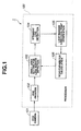
- Fig. 1 is a block diagram showing an embodiment of a lane recognition apparatus 1 for a vehicle, not according to the invention.
- Lane recognition apparatus 1 for a vehicle comprises a CCD camera 101 for picking up an image of a scene of a road in front of the vehicle (image pickup section), a pre-process section 102 for uniformly processing an entire screen of a video signal from CCD camera 101, a lane marker detecting small area setting section 103 for setting a plurality of small areas for detecting a lane marker on an input screen, a straight line detecting section 104 for detecting parts of the lane marker in the plurality of small areas, a lane marker candidate point verifying section 105 for verifying that results of straight line detection are parts of the lane marker, and a road parameter calculating section 106 for calculating road model parameters (road parameters) for representing the shape of the road in front of the vehicle and the state of the vehicle relative to the road based on the result of lane marker detection.
- road parameters road parameters
- the lane recognition apparatus 1 comprises a processor 100 which is constituted by a microcomputer and which is coupled to CCD camera 101.
- the microcomputer is arranged to store the sections 101 through 106 of the lane recognition apparatus in the form of software and to perform the processes of the sections 101 through 106 by executing a program control in processor 100.
- lane recognition apparatus 1 is started when a switch is operated by the driver, or the vehicle is started, at step 201, and road parameters for recognizing the shape of a road in front of the vehicle and the state of the vehicle relative to the road are initialized at step 202.
- a road coordinate system is defined as an XYZ system in which the center of an image pickup lens of CCD camera 101 is the origin.
- the X-axis extends from the right to the left as viewed in the traveling direction of the vehicle.
- the Y-axis extends upward in the direction of the height of the vehicle.
- the Z-axis is the optical axis of the lens in the traveling direction of the vehicle.
- a plane coordinate system of an image processing screen is defined in which the origin is at the upper left corner of the screen.
- the x-axis horizontally extends from the left to the right, and the y-axis vertically extends from the top to the bottom.
- Equations (1) and (2) shown below where the origin of the plane coordinate system is located on the Z-axis of the road coordinate system as shown in Fig. 7.
- x -fX/Z
- y -fY/Z
- f represents a parameter that represents the focal length of the lens.
- a planar structure of a road is defined by straight lines, curves having constant curvatures, and clothoid curves having constant curvature change rates for connecting them
- a section of the road of several tens of meters in front of a vehicle can be regarded as a curved road having a constant curvature or a straight road.
- the shape of a lane marker is formulated as shown in Fig. 3A.
- a longitudinal structure of the same is formulated as shown in Fig. 3B because it can be regarded as having a constant gradient.
- ⁇ represents the curvature of the road
- ⁇ represents a yaw angle of the vehicle to a lane marker
- y C represents lateral displacement of the vehicle from a left lane marker
- W represents the lane width
- i represents the left line marker when it is 0 and represents a right lane marker when it is 1
- ⁇ represents a pitch angle of the optical axis of the lens to the road surface
- h represents the height of the camera above the ground.
- Equations (1) through (4) The shape of a lane marker projected on the plane coordinate system of the image processing screen can be formulated from Equations (1) through (4). Equations (1) through (4) can be rearranged by eliminating X, Y, and Z to obtain the following Equations (5) through (10).
- c 0 and d 0 are correction values that are required because the actual origin is located at the upper left corner of the image processing screen in spite of the fact that the origin of the plane coordinate system is on the Z-axis in the road coordinate system in Fig. 7.
- Fig. 4 shows an association between an example of a two-dimensional road model and parameters a through e on a screen.
- an image signal of an image as shown in Fig. 4 picked up by CCD camera 101 is inputted to pre-processing section 102 which performs a pre-process on the same.
- pre-processing section 102 which performs a pre-process on the same.
- primary space differentiation is performed with a Sobel Filter to emphasize a boundary between the lane marker and a road surface.
- the object of lane marker detection is such a boundary. Since a lane marker has regions which are nearly horizontal and regions which are nearly vertical depending on the curvature of the road, two edge images are created using horizontal differentiation and vertical differentiation. Other edge emphasizing filters may be used to emphasize a boundary between the lane marker and road surface.
- a plurality of small areas are set in order to detect a lane marker which indicates the lane in which the vehicle is traveling on the screen.
- the detection areas are set as predetermined sections defined along the shape of the road identified from the results of the previous image processing or road parameters which have been initially set.
- sections 1 through 5 are set such that they become equal distances when the screen is transformed into an actual three-dimensional road coordinate system.
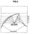
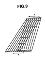
- straight lines are detected in the small regions set at step 204. Specifically, if a boundary between the lane marker in a certain small area and the road surface is identified as indicated by the black solid lines in Fig. 5 from the results of the previous image processing or initial setting, the position of the boundary at this time may undergo changes in the form of parallel movement as shown in Fig. 8A and changes of the inclination as shown in Fig. 8B. Then, those changes are combined to set a trapezoidal small area as shown in Fig. 9 as a detection area, and line segments extending across the top and bottom sides are to be detected.
- the size of the detection area is determined by the range p of the lateral behavior and the range q of the inclinational behavior, and p ⁇ q line segments are to be detected.
- the sum of edge strengths of pixels that make up each of the line segments on an edge image is calculated for each of the line segments, and the coordinates of the starting and end points of the line segment having the greatest sum are outputted as a result of the detection.
- step 206 it is verified whether the result of the detection at step 205 can support a judgment that a part of a lane marker has been detected.
- a road has many noises other than lane markers, including joints of pavement, shadows, and cars traveling ahead.
- conditions as described below are taken into consideration when using a result of straight line detection as a candidate point of a lane marker.
- the range of changes in the position of a lane marker candidate point is first limited by the time required for processing the image, the vehicle speed, and the shape of the road. Since a lane marker is a white or yellow line, it has a pair of rows of positive and negative edge points. Further, the movement of a certain lane marker candidate point is correlated with the movement of other candidate points.
- a result of straight line detection which satisfies such conditions is used as a lane marker candidate point for estimating parameters of a road model.
- parameters for the road model are calculated from the position of the lane marker candidate point on the screen obtained at step 206.
- an extended Kalman filter is used as means for estimating an equation for a two-dimensional road model based on a result of detection of a lane marker candidate point through image processing.
- Equation (11) is derived from the above-described Equations (1) through (4). This equation is used as an output equation in configuring an extended Kalman filter, and the value of an x-coordinate at a y-coordinate value defined on a plane under image processing is calculated from the road curvature and vehicle state quantity.
- x (- y c h + i W h ) (y + f ⁇ ) + f 2 h ⁇ 2(y + f ⁇ ) - f ⁇
- the estimated state quantity in the extended Kalman filter includes lateral displacement y C of the vehicle, road curvature ⁇ , vehicle yaw angle ⁇ , pitch angle ⁇ , and height h of CCD camera 101. Further, the focal length f of the lens and the lane width W are treated as constant values.
- Equation (12) shown below is obtained if it is defined as a random walk model in a discrete system which is driven by white Gaussian noises ⁇ on the assumption that a change of each estimated state quantity behaves stochastically.
- Equation (12) and Output Equation (11) are simplified into Equations (13) and (14) shown below, the extended Kalman filter is configured by Equations (15) through (18).
- k) A S x S (k
- k - 1) , y(k)) ⁇ K(k) A S P(k)C T (CP(k)C T +R) -1
- Equation (19) A state equation in this case is given as Equation (19) shown below.
- Equation (19) ⁇ is a parameter for setting a frequency band in which disturbances can be introduced, and w represents white noises having an average value of 0.
- ⁇ ( ⁇ ) 2 ⁇ X 0 2 ( ⁇ 2 + ⁇ 2 )
- ⁇ X and w can be defined from actual traveling conditions.
- a Poisson square wave is used here, any other model allowing understanding of actual traveling conditions of a vehicle may be used.
- step 208 it is judged at step 208 whether the road shape has been correctly estimated from road model parameters a through e obtained at step 207.
- parameter a for example, when the lateral position of the vehicle calculated from parameter a exceeds a predetermined range or when a change (in the speed in the lateral direction) from the result of the previous image processing exceeds a predetermined value, it is judged that the estimation of the road shape from road model parameters a through e is incorrect. This similarly applies to parameters b through e, and the estimation of the road shape from road model parameters a through e is judged to be incorrect when a physical quantity calculated from each of the parameters exceeds a predetermined range or when quantities of change of them exceed predetermined values. If the estimation of the road shape is judged to be correct, the process proceeds to subsequent step 209, and the process returns to step 202 to be re-executed from the initializing process when the estimation of the road shape is judged to be incorrect.
- step 209 the road parameters calculated at step 207 are preserved in a data storage area. Thereafter, the process returns to step 203 to acquire an image to perform processing of the next screen.
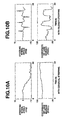
- Figs. 10A and 10B show time charts (time-series changes) of a coordinate system of a lane marker candidate point projected on the surface of the CCD.
- a lane marker candidate point moves gently as shown in Fig. 10A.
- a lane marker candidate point moves at a high speed which does not occur during automatic driving.
- Fig. 11 shows erroneous recognition of a lane marker candidate point caused by a road surface that is wetted by rain.
- a state estimator when a state estimator is configured based on an assumption that all movements of a lane marker candidate point are stochastic changes, erroneous recognition frequently occurs in bad weather if high dynamic characteristics of candidate points are set in the estimator, although an estimated value will follow up a true value with high performance when the steering wheel is operated. On the contrary, if low dynamic characteristics are set in the estimator, a problem arises in that an estimated value will be delayed from a true value when the steering wheel is operated.
- a yaw angle or lateral displacement caused by disturbances such as a transverse gradient of a road or side wind has a low frequency band
- a yaw angle or lateral displacement caused by a steering angle has a sufficiently high frequency band. Therefore, the above-described problem can be solved by identifying whether a yaw angle or lateral displacement is caused as a result of input of a steering angle.
- pitching and bouncing caused by a curvature of a road or an irregular road surface are regarded as stationary stochastic processes, and motions of a vehicle caused by the input of a steering angle are treated as deterministic states based on a vehicle model.
- a movement of a lane marker candidate point projected on the surface of the CCD is represented as a combination of a stochastic behavior caused by a disturbance acting on the vehicle and a deterministic behavior in accordance with a steering angle.
- an extended Kalman filter By configuring an extended Kalman filter in such a manner, it is possible to reduce erroneous recognition of a lane marker attributable to noises on a road surface while maintaining preferable properties of following up a quick behavior of the vehicle at the input of a steering angle.
- lane recognition apparatus 1 for a vehicle of the second embodiment comprises CCD camera 101 for picking up an image of a scene of a road in front of the vehicle (which corresponds to an image pickup section), pre-process section 102 for uniformly processing an entire screen of a video signal from CCD camera 101, lane marker detecting small area setting section 103 for setting a plurality of small areas for detecting a lane marker on an input screen, straight line detecting section 104 for detecting parts of the lane marker in the plurality of small areas, lane marker candidate point verifying section 105 for verifying that results of straight line detection are parts of the lane marker, road parameter calculating section 106 for calculating road model parameters (road parameters) for representing the shape of the road in front of the vehicle and the state of the vehicle relative to the road based on the result of lane marker detection, a steering angle detecting section 108 for detecting a steering angle of the vehicle and transmitting the same to road parameter calculating section 106, and a vehicle
- Equation (23) A longitudinal structure of the same is expressed by Equation (23) similarly to the above-described first embodiment.
- ⁇ represents the curvature of the road
- ⁇ r represents a yaw angle of the vehicle to the centerline of the road
- y Cr represents lateral displacement of the center of gravity of the vehicle from the centerline of the road
- i is a lane marker number which represents a left lane marker when it is 0 and represents a right lane marker when it is 1
- W represents lane width
- Z represents a distance in front of the vehicle from the center of the lens
- X represents a distance to the left of the vehicle from the center of the lens
- ⁇ represents a pitch angle of the vehicle
- h represents the height of the center of the lens above the road surface.
- Equation (1), (2), (22),and (23) The shape of a lane marker projected on a plane coordinate system of an image processing screen can be formulated from Equations (1), (2), (22),and (23). Equations (1), (2), (22), and (23) can be rearranged to obtain the following Equation (24):
- the present embodiment is aimed at estimating the shape of a road and the state of the vehicle relative to the road from a combination of (x, y) and a steering angle, and the following State Equation (25) is based on a common two-wheeled model.
- Constants a 11 , a 12 , a 13 , a 31 , a 32 , a 33 , b 11 , and b 31 in Equation (25) are constants determined by the vehicle specifications shown below.
- a 11 l 2 f C f + l 2 r C r VI
- a 12 l f C f + l r C r I
- a 13 - l f C f + l r C r VI
- a 31 - l f C f + l r C r mV
- a 32 C f + C r m
- a 33 - C f + C r mV
- l f (l r ) represents the distance between the center of gravity and the front (or rear) wheel
- C f (C r ) represents the full cornering power of the front
- parameters of a road model are calculated from the position of a lane marker candidate point on a screen obtained at step 206.
- An extended Kalman filter is used also in the present embodiment as means for estimating an equation for a two-dimensional road model based on the result of detection of a lane marker candidate point through image processing.
- Equation (27) A state equation of the vehicle is expressed by the following Equation (27) in which M and F represent a yaw moment and a lateral force originating from disturbances acting on the vehicle; and [ ⁇ ⁇ ⁇ ⁇ ⁇ h ⁇ M ⁇ F ] T are put on an assumption of the presence of white Gaussian noises.
- q ⁇ , q ⁇ , q h , q M , and q F represent standard deviations of disturbances that drive the respective state variables.
- the yaw moment and lateral force of disturbances are treated as state variables here to improve lane follow-up properties by providing feedback of those state quantities and to absorb any shift of the steering wheel from a neutral position during a straight drive due to a stationary transverse gradient of a road or a side wind or any shift of the steering wheel from the neutral position at the time of shipment.
- Equation (27) is simplified into the following Equation (28) in a discrete form with the state variables maintained.
- X S (k+1) A S x S (k) + G S v(k)
- X S (k) [ ⁇ T (k) ⁇ r (k) y C T (k) y C T (k) ⁇ T (k) ⁇ T (k) h T (k) M T (k) F T (k)] T
- a state variable vector is accompanied by a suffix "S" as represented by "X S " in order to prevent it from being mistaken as the x of the coordinates of the CCD surface.
- An output x is the x-coordinate value of a pixel of the CCD surface.
- the output equation is a non-linear function of the state variables as indicated by Equation (24). Specifically, (x, y) coordinate values are the coordinates of lane marker candidate points, ten points being selected in total for left and right line markers, the y-coordinate system being a fixed value.
- the output equation for a j-th (j ranges from 1 to 10) x-coordinate is as expressed by the following Equation (29):
- Equation (29) is simplified into the following Equation (30).
- g(X s , y) represents a non-linear function of X s and y.
- x g(x S ,y)
- k) A S x S (k
- k - 1), y(k)) ⁇ K(k) A S P(k)C T (CP(k)C T +R) -1
- the parameters for the road model are obtained using the extended Kalman filter, and it is judged at subsequent step 208 whether the road shape has been correctly estimated from road model parameters a through e obtained at step 207 just as in the first embodiment described above. If the estimation of the road shape is judged to be correct, the process proceeds to subsequent step 209, and the process returns to step 202 to be re-executed from the initializing process when the estimation of the road shape is judged to be incorrect.
- step 209 the road parameters calculated at step 207 are preserved in a data storage area. Thereafter, the process returns to step 203 to acquire an image to perform processing of the next screen.
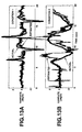
- Figs. 13A and 13B show results of estimation by the extended Kalman filter for which no steering angle information was considered and in which high dynamic characteristics were set.
- Fig. 13A shows a result of estimation under the condition (1)
- Fig. 13B shows a result of estimation under the condition (2).
- the estimated value follows up the true value with high response when a steering angle is quickly inputted per the condition (1) described above.
- estimation errors having great amplitudes occur in this state when there are many noises on the road surface as experienced under the condition (2).
- Figs. 14A and 14B show results of estimation by the extended Kalman filter for which no steering angle information was considered and in which low dynamic characteristics were set.
- Fig. 14A shows a result of estimation under the condition (1)
- Fig. 14B shows a result of estimation under the condition (2).
- estimation errors at the time of erroneous recognition have amplitudes smaller than those in the example shown in Figs. 13A and 13B, it is apparent that the dynamic characteristics of the estimator are too low to obtain correct estimation values.
- the extended Kalman filter for which no steering angle information is considered has tradeoff between the property of following up a true value (speed of estimation) and estimation errors at the time of erroneous recognition (anti-noise performance).
- Figs. 15A and 15B show results of estimation according to the present invention.
- the results of the estimation were obtained using the extended Kalman filter for which steering angle information was considered.
- Fig. 15A shows a result of estimation under the condition (1)
- Fig. 15B shows a result of estimation under the condition (2).
- the dynamic characteristics of the extended Kalman filter of this example were kept constant regardless of the conditions.
- the results show that the extended Kalman filter for which steering angle information is considered can overcome the tradeoff that is a problem in the extended Kalman filters shown in Figs. 13A, 13B, 14A, and 14B because the vehicle behavior caused by a steering angle is modeled.
- conventional lane tracking systems are constituted by an image processing system for estimating lateral displacement of a point for forward observation by detecting a lane marker and a steering control system operating based on information from the same.
- a control system utilizing estimated values of intermediate variables such as lateral displacement of a point for forward observation is useless for optimal control of a steering system.
- H 2 control can be easily configured by extending the above-described Equation (27) as it is into a generalized plant.
- the extended Kalman filter represented by Equations (31) through (34) is used for estimating state quantities, and a feedback gain obtained to allow observation of all states is used for a regulator (state feedback section). This makes it possible to minimize H 2 norm from disturbance w to control quantity z on an approximated basis while it is a non-linear system.
- Equations (35) a generalized plant equivalent to an optimal regulator is configured, and Q is a weight for lateral displacement. Frequency shaping may be adopted instead of such a scalar weight.
- a T H + HA - HB 2 B 2 H T + C T 1 C 1 0
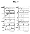
- Fig. 18 shows examples of lane markers used in a simulation (of a travel around a corner bent to the left).
- the shapes and positions of lane markers projected on a screen change with the vehicle depending on the curvature and a state quantity of the vehicle.
- Fig. 19 shows comparison between values estimated with a Kalman filter and true state quantities during the simulation when the vehicle enters a curved section having no transition curve on an automatic steering basis.
- Fig. 19 shows that an actual state and an estimated value preferably match even when a steering angle is quickly inputted.
Description
- The present invention relates to an apparatus for recognizing a lane on which a vehicle travels.
- Various lane recognition apparatuses have been proposed in order to assist a driver to drive a vehicle along a lane or to automatically drive a vehicle. Japanese Patent Provisional Publication No. 8-5388 discloses a method for estimating a road shape using a least square method.
- EP-A-0 810 569 discloses a lane recognition apparatus and method according to the respective preambles of the independent claims.
- However, the prior art yet includes several problems to be improved in order to further accurately and stably estimate a road shape.
- It is therefore an object of the present invention to provide an improved lane recognition apparatus which is capable of accurately estimating a road shape (a lane) while stably performing the estimation against disturbances.
- The main aspect of the present invention resides in a lane recognition apparatus as set forth in claim 1. Such a lane recognition apparatus comprises a camera and a processor. The camera picks up a road image in front of the vehicle. The processor is coupled to the camera and is arranged to calculate coordinate values of a plurality of lane marker candidate points from the road image, to estimate a road model parameter representative of a road shape in front of the vehicle and a vehicle state quantity from an extended Kalman filter and the coordinate values of the lane marker candidate points.
- A further aspect of the present invention resides in a method for recognizing a lane in front of a vehicle. The method is set forth in claim 6.
- Optional and preferred features of this invention will become understood from the following description with reference to the accompanying drawings.
-
- Fig. 1 is a block diagram showing a first embodiment of a lane recognition apparatus for a vehicle, not according to the present invention.
- Fig. 2 is a flowchart showing an information processing procedure of the lane recognition apparatus of Fig. 1.
- Figs. 3A and 3B are a plan view and a side view which show a road model employed in the first embodiment.
- Fig. 4 is a view showing the image picture on which the road model is developed.
- Fig. 5 is an explanatory view for explaining lane marker detecting areas.
- Fig. 6 is a block diagram showing a second embodiment of a lane recognition apparatus of a vehicle, according to the present invention.
- Fig. 7 is a view showing coordinates of the road model according to the present invention.
- Figs. 8A and 8B are explanatory views employed for explaining a straight line detection executed by the lane recognition process.
- Fig. 9 is another explanatory view employed for explaining the straight line detection.
- Figs. 10A and 10B are time charts showing the lane marker candidate point which is influenced by a steering angle.
- Fig. 11 is time charts showing the lane marker candidate point influenced by noises on a road surface.
- Fig. 12 is a time chart showing the lane marker candidate point influenced by noises on a road surface.
- Figs. 13A and 13B are time charts showing the lane marker candidate point influenced by the steering angle.
- Figs. 14A and 14B are time charts showing the lane marker candidate point influenced by the steering angle.
- Figs. 15A and 15B are time charts showing the lane marker candidate point influenced by the steering angle.
- Fig. 16 shows time charts employed for explaining a merit of a first-order lag of a continuous system of a state equation of the Kalman filter according to the present invention.
- Fig. 17 is a plan view showing the road model employed in the second embodiment of the lane recognition apparatus, according to the present invention.
- Fig. 18 is a view showing a simulation result of the second embodiment, according to the present invention.
- Fig. 19 are graphs showing the simulation result of the second embodiment.
-
- Embodiments of a lane recognition apparatus will now be described based on the drawings.
- Fig. 1 is a block diagram showing an embodiment of a lane recognition apparatus 1 for a vehicle, not according to the invention. Lane recognition apparatus 1 for a vehicle according to the present embodiment comprises a CCD camera 101 for picking up an image of a scene of a road in front of the vehicle (image pickup section), a pre-process section 102 for uniformly processing an entire screen of a video signal from CCD camera 101, a lane marker detecting small area setting section 103 for setting a plurality of small areas for detecting a lane marker on an input screen, a straight line detecting section 104 for detecting parts of the lane marker in the plurality of small areas, a lane marker candidate point verifying section 105 for verifying that results of straight line detection are parts of the lane marker, and a road parameter calculating section 106 for calculating road model parameters (road parameters) for representing the shape of the road in front of the vehicle and the state of the vehicle relative to the road based on the result of lane marker detection.
- The lane recognition apparatus 1 comprises a processor 100 which is constituted by a microcomputer and which is coupled to CCD camera 101. The microcomputer is arranged to store the sections 101 through 106 of the lane recognition apparatus in the form of software and to perform the processes of the sections 101 through 106 by executing a program control in processor 100.
- Now, there will be described steps for recognizing a lane executed by lane recognition apparatus 1, with reference to Fig. 2.
- First, lane recognition apparatus 1 is started when a switch is operated by the driver, or the vehicle is started, at step 201, and road parameters for recognizing the shape of a road in front of the vehicle and the state of the vehicle relative to the road are initialized at step 202.
- The road parameters are defined according to the following procedure. As shown in Figs. 3A and 3B, a road coordinate system is defined as an XYZ system in which the center of an image pickup lens of CCD camera 101 is the origin. The X-axis extends from the right to the left as viewed in the traveling direction of the vehicle. The Y-axis extends upward in the direction of the height of the vehicle. The Z-axis is the optical axis of the lens in the traveling direction of the vehicle. As shown in Fig. 4, a plane coordinate system of an image processing screen is defined in which the origin is at the upper left corner of the screen. The x-axis horizontally extends from the left to the right, and the y-axis vertically extends from the top to the bottom. These definition are in accordance with the direction in which a screen is scanned in television communication systems such as NTSC.
- The relationship between those two coordinate systems is as shown in Fig. 7 and, for simplicity, coordinate transformation from the road coordinate system to the plane coordinate system is expressed by Equations (1) and (2) shown below where the origin of the plane coordinate system is located on the Z-axis of the road coordinate system as shown in Fig. 7.
- While a planar structure of a road is defined by straight lines, curves having constant curvatures, and clothoid curves having constant curvature change rates for connecting them, a section of the road of several tens of meters in front of a vehicle can be regarded as a curved road having a constant curvature or a straight road. Then, the shape of a lane marker is formulated as shown in Fig. 3A. Similarly, a longitudinal structure of the same is formulated as shown in Fig. 3B because it can be regarded as having a constant gradient. The formulae are respectively given as Equations (3) and (4) below.
- The shape of a lane marker projected on the plane coordinate system of the image processing screen can be formulated from Equations (1) through (4). Equations (1) through (4) can be rearranged by eliminating X, Y, and Z to obtain the following Equations (5) through (10).
- The terms c0 and d0 are correction values that are required because the actual origin is located at the upper left corner of the image processing screen in spite of the fact that the origin of the plane coordinate system is on the Z-axis in the road coordinate system in Fig. 7.
- It is apparent from the above that the curvature of the road, the pitch angle and yaw angle of the vehicle, and the lateral displacement of the vehicle within the lane can be estimated by identifying values of parameters a through e in Equation (5) which are satisfied by a lane marker candidate point detected through image processing. Fig. 4 shows an association between an example of a two-dimensional road model and parameters a through e on a screen.
- Returning to Fig. 2, at step 203 an image signal of an image as shown in Fig. 4 picked up by CCD camera 101 is inputted to pre-processing section 102 which performs a pre-process on the same. For example, as a pre-process for detecting a lane marker, primary space differentiation is performed with a Sobel Filter to emphasize a boundary between the lane marker and a road surface. The object of lane marker detection is such a boundary. Since a lane marker has regions which are nearly horizontal and regions which are nearly vertical depending on the curvature of the road, two edge images are created using horizontal differentiation and vertical differentiation. Other edge emphasizing filters may be used to emphasize a boundary between the lane marker and road surface.
- At subsequent step 204 a plurality of small areas are set in order to detect a lane marker which indicates the lane in which the vehicle is traveling on the screen. As shown in Fig. 5, the detection areas are set as predetermined sections defined along the shape of the road identified from the results of the previous image processing or road parameters which have been initially set. At this time, sections 1 through 5 are set such that they become equal distances when the screen is transformed into an actual three-dimensional road coordinate system.
- At step 205 straight lines are detected in the small regions set at step 204. Specifically, if a boundary between the lane marker in a certain small area and the road surface is identified as indicated by the black solid lines in Fig. 5 from the results of the previous image processing or initial setting, the position of the boundary at this time may undergo changes in the form of parallel movement as shown in Fig. 8A and changes of the inclination as shown in Fig. 8B. Then, those changes are combined to set a trapezoidal small area as shown in Fig. 9 as a detection area, and line segments extending across the top and bottom sides are to be detected. The size of the detection area is determined by the range p of the lateral behavior and the range q of the inclinational behavior, and p × q line segments are to be detected. The sum of edge strengths of pixels that make up each of the line segments on an edge image is calculated for each of the line segments, and the coordinates of the starting and end points of the line segment having the greatest sum are outputted as a result of the detection.
- At subsequent step 206, it is verified whether the result of the detection at step 205 can support a judgment that a part of a lane marker has been detected. A road has many noises other than lane markers, including joints of pavement, shadows, and cars traveling ahead. In order to prevent erroneous detection of straight line segments originating from such noises, conditions as described below are taken into consideration when using a result of straight line detection as a candidate point of a lane marker.
- Specifically, the range of changes in the position of a lane marker candidate point is first limited by the time required for processing the image, the vehicle speed, and the shape of the road. Since a lane marker is a white or yellow line, it has a pair of rows of positive and negative edge points. Further, the movement of a certain lane marker candidate point is correlated with the movement of other candidate points.
- A result of straight line detection which satisfies such conditions is used as a lane marker candidate point for estimating parameters of a road model.
- At subsequent step 207 parameters for the road model are calculated from the position of the lane marker candidate point on the screen obtained at step 206. In the present embodiment, an extended Kalman filter is used as means for estimating an equation for a two-dimensional road model based on a result of detection of a lane marker candidate point through image processing.
- The following Equation (11) is derived from the above-described Equations (1) through (4). This equation is used as an output equation in configuring an extended Kalman filter, and the value of an x-coordinate at a y-coordinate value defined on a plane under image processing is calculated from the road curvature and vehicle state quantity.
- The estimated state quantity in the extended Kalman filter includes lateral displacement yC of the vehicle, road curvature ρ, vehicle yaw angle , pitch angle η, and height h of CCD camera 101. Further, the focal length f of the lens and the lane width W are treated as constant values. A state equation expressed as Equation (12) shown below is obtained if it is defined as a random walk model in a discrete system which is driven by white Gaussian noises ν on the assumption that a change of each estimated state quantity behaves stochastically.

- When State Equation (12) and Output Equation (11) are simplified into Equations (13) and (14) shown below, the extended Kalman filter is configured by Equations (15) through (18).
- While the state equation has configured as a random walk model in a discrete system in the above description, it may be represented as a first-order lag in a continuous system. A state equation in this case is given as Equation (19) shown below.

- In Equation (19), λ is a parameter for setting a frequency band in which disturbances can be introduced, and w represents white noises having an average value of 0. In this case, each estimated state quantity X is expressed by the following equation (20).
- A power spectral density Φ (ω) is obtained which is equivalent to a Poisson's square wave having a 0-crossing frequency of N per second and an amplitude X0 where λX = 2N and variance of w is 2λXX0 2.
- Therefore, even if actual changes in the estimated state quantities are different from those in a Poisson square wave, since an average value of the changes and the behavior of the same related to variance agree with those in a Poisson square wave, λX and w can be defined from actual traveling conditions. Although a Poisson square wave is used here, any other model allowing understanding of actual traveling conditions of a vehicle may be used.
- Since a straight line and a curve are connected by a clothoid curve in an actual road structure, an estimation result close to the actual road shape can be obtained as shown in Fig. 16 by estimating the change in the curvature with a first-order lag.
- Returning to Fig. 2, it is judged at step 208 whether the road shape has been correctly estimated from road model parameters a through e obtained at step 207. Referring to parameter a for example, when the lateral position of the vehicle calculated from parameter a exceeds a predetermined range or when a change (in the speed in the lateral direction) from the result of the previous image processing exceeds a predetermined value, it is judged that the estimation of the road shape from road model parameters a through e is incorrect. This similarly applies to parameters b through e, and the estimation of the road shape from road model parameters a through e is judged to be incorrect when a physical quantity calculated from each of the parameters exceeds a predetermined range or when quantities of change of them exceed predetermined values. If the estimation of the road shape is judged to be correct, the process proceeds to subsequent step 209, and the process returns to step 202 to be re-executed from the initializing process when the estimation of the road shape is judged to be incorrect.
- At step 209, the road parameters calculated at step 207 are preserved in a data storage area. Thereafter, the process returns to step 203 to acquire an image to perform processing of the next screen.
- The processes in the present embodiment are performed according to the above procedure.
- While changes in the parameters have been described as being driven by independent white Gaussian noises in the first embodiment, since such changes have some correlation with changes in the yaw angle and the lateral position, changes in the pitch angle and the camera height, and changes in the curvature and yaw angle, a state equation may be configured in consideration of those factors.
- Figs. 10A and 10B show time charts (time-series changes) of a coordinate system of a lane marker candidate point projected on the surface of the CCD. When the vehicle is gradually steered along the lane as in the case of automatic driving, a lane marker candidate point moves gently as shown in Fig. 10A. On the contrary, when the steering wheel is operated suddenly as shown in Fig. 10B, a lane marker candidate point moves at a high speed which does not occur during automatic driving. Even when the steering wheel is gradually operated, erroneous recognition of a lane marker can be caused by a noise on the road surface to cause an abrupt change in the coordinate of a lane marker candidate point. Fig. 11 shows erroneous recognition of a lane marker candidate point caused by a road surface that is wetted by rain.
- As described above, when a state estimator is configured based on an assumption that all movements of a lane marker candidate point are stochastic changes, erroneous recognition frequently occurs in bad weather if high dynamic characteristics of candidate points are set in the estimator, although an estimated value will follow up a true value with high performance when the steering wheel is operated. On the contrary, if low dynamic characteristics are set in the estimator, a problem arises in that an estimated value will be delayed from a true value when the steering wheel is operated.
- A yaw angle or lateral displacement caused by disturbances such as a transverse gradient of a road or side wind has a low frequency band, while a yaw angle or lateral displacement caused by a steering angle has a sufficiently high frequency band. Therefore, the above-described problem can be solved by identifying whether a yaw angle or lateral displacement is caused as a result of input of a steering angle.
- In the present embodiment, pitching and bouncing caused by a curvature of a road or an irregular road surface are regarded as stationary stochastic processes, and motions of a vehicle caused by the input of a steering angle are treated as deterministic states based on a vehicle model. Thus, a movement of a lane marker candidate point projected on the surface of the CCD is represented as a combination of a stochastic behavior caused by a disturbance acting on the vehicle and a deterministic behavior in accordance with a steering angle. By configuring an extended Kalman filter in such a manner, it is possible to reduce erroneous recognition of a lane marker attributable to noises on a road surface while maintaining preferable properties of following up a quick behavior of the vehicle at the input of a steering angle.
- As shown in Fig. 6, lane recognition apparatus 1 for a vehicle of the second embodiment, according to the present invention, comprises CCD camera 101 for picking up an image of a scene of a road in front of the vehicle (which corresponds to an image pickup section), pre-process section 102 for uniformly processing an entire screen of a video signal from CCD camera 101, lane marker detecting small area setting section 103 for setting a plurality of small areas for detecting a lane marker on an input screen, straight line detecting section 104 for detecting parts of the lane marker in the plurality of small areas, lane marker candidate point verifying section 105 for verifying that results of straight line detection are parts of the lane marker, road parameter calculating section 106 for calculating road model parameters (road parameters) for representing the shape of the road in front of the vehicle and the state of the vehicle relative to the road based on the result of lane marker detection, a steering angle detecting section 108 for detecting a steering angle of the vehicle and transmitting the same to road parameter calculating section 106, and a vehicle speed detecting section 107 for detecting a traveling speed of the vehicle and transmitting the same to road parameter calculating section 106.
- Steps for recognizing a lane will now be described.
- Since some of the steps for recognizing a lane in the second embodiment are the same as those in the flow chart shown in Fig. 2, the following description will be focused on differences from the first embodiment with reference to Fig. 2.
- In the second embodiment, a road model is defined as indicated by the plan view in Fig. 17. It is different from Fig. 3A in that the second embodiment shown in Fig. 17 uses lateral displacement yCr of a vehicle relative to a centerline of a road, unlike Fig. 3A in which lateral displacement yC of a vehicle relative to a left line marker is used as lateral displacement of the vehicle. It should be noted that yC = W/2 - yCr.
- While processes at steps 201 and 202 shown in Fig. 2 are the same as those in the above described first embodiment, the shape of a lane marker shown in Fig. 17 is expressed by Equation (22) shown below from the relationship expressed by yC = W/2 - yCr. A longitudinal structure of the same is expressed by Equation (23) similarly to the above-described first embodiment.
- The shape of a lane marker projected on a plane coordinate system of an image processing screen can be formulated from Equations (1), (2), (22),and (23). Equations (1), (2), (22), and (23) can be rearranged to obtain the following Equation (24):

- The present embodiment is aimed at estimating the shape of a road and the state of the vehicle relative to the road from a combination of (x, y) and a steering angle, and the following State Equation (25) is based on a common two-wheeled model.

- Constants a11, a12, a13, a31, a32, a33, b11, and b31 in Equation (25) are constants determined by the vehicle specifications shown below.
Cf(Cr) represents the full cornering power of the front (rear) wheels for two wheels; m represents the vehicle weight; I represents a yawing moment of inertia of the vehicle; represents a steering angle; N represents a steering gear ratio; V represents the vehicle speed; and represents a yaw rate. - The same processes as those in the above-described first embodiment are performed at steps 203 through 206.
- At subsequent step 207, parameters of a road model are calculated from the position of a lane marker candidate point on a screen obtained at step 206. An extended Kalman filter is used also in the present embodiment as means for estimating an equation for a two-dimensional road model based on the result of detection of a lane marker candidate point through image processing.
- A behavior of a stochastic state variable ξ for the curvature ρ, pitch angle η, the quantity of a bounce h, and various disturbances is approximated as a first-order system driven by white noises as indicated by the following Equation (26):

- Equation (27) is simplified into the following Equation (28) in a discrete form with the state variables maintained.
- A state variable vector is accompanied by a suffix "S" as represented by "XS" in order to prevent it from being mistaken as the x of the coordinates of the CCD surface. An output x is the x-coordinate value of a pixel of the CCD surface. The output equation is a non-linear function of the state variables as indicated by Equation (24). Specifically, (x, y) coordinate values are the coordinates of lane marker candidate points, ten points being selected in total for left and right line markers, the y-coordinate system being a fixed value. The output equation for a j-th (j ranges from 1 to 10) x-coordinate is as expressed by the following Equation (29):

- Equation (29) is simplified into the following Equation (30). g(Xs, y) represents a non-linear function of Xs and y.
- The extended Kalman filter is expressed by the following Equations (31) through (34).
- The parameters for the road model are obtained using the extended Kalman filter, and it is judged at subsequent step 208 whether the road shape has been correctly estimated from road model parameters a through e obtained at step 207 just as in the first embodiment described above. If the estimation of the road shape is judged to be correct, the process proceeds to subsequent step 209, and the process returns to step 202 to be re-executed from the initializing process when the estimation of the road shape is judged to be incorrect.
- At step 209 the road parameters calculated at step 207 are preserved in a data storage area. Thereafter, the process returns to step 203 to acquire an image to perform processing of the next screen.
- Evaluation and comparison of performance was conducted between an extended Kalman filter utilizing a cause-effect relationship between state quantities of a vehicle caused by a steering angle and an extended Kalman filter for which no steering angle information was considered, with reference to a yaw rate which was actually measured with a gyroscope loaded on the vehicle. Referring to conditions for the evaluation, they were evaluated under two conditions, i.e., (1) a steering angle was abruptly inputted, and (2) erroneous recognition of a lane marker was caused by noises on a road surface. Since a lane marker candidate point is detected through edge processing as a basic process, contrast caused by noises such as rain on the road is erroneously recognized under the condition (2). This results in a discontinuous behavior as shown in Fig. 12.
- First, Figs. 13A and 13B show results of estimation by the extended Kalman filter for which no steering angle information was considered and in which high dynamic characteristics were set. Fig. 13A shows a result of estimation under the condition (1) and Fig. 13B shows a result of estimation under the condition (2). As shown in Fig. 13A, the estimated value follows up the true value with high response when a steering angle is quickly inputted per the condition (1) described above. However, as apparent from Fig. 13B, estimation errors having great amplitudes occur in this state when there are many noises on the road surface as experienced under the condition (2).
- Figs. 14A and 14B show results of estimation by the extended Kalman filter for which no steering angle information was considered and in which low dynamic characteristics were set. Fig. 14A shows a result of estimation under the condition (1) and Fig. 14B shows a result of estimation under the condition (2). In this case, while estimation errors at the time of erroneous recognition have amplitudes smaller than those in the example shown in Figs. 13A and 13B, it is apparent that the dynamic characteristics of the estimator are too low to obtain correct estimation values.
- Thus, the extended Kalman filter for which no steering angle information is considered has tradeoff between the property of following up a true value (speed of estimation) and estimation errors at the time of erroneous recognition (anti-noise performance).
- On the contrary, Figs. 15A and 15B show results of estimation according to the present invention. The results of the estimation were obtained using the extended Kalman filter for which steering angle information was considered. Fig. 15A shows a result of estimation under the condition (1) and Fig. 15B shows a result of estimation under the condition (2). The dynamic characteristics of the extended Kalman filter of this example were kept constant regardless of the conditions. The results show that the extended Kalman filter for which steering angle information is considered can overcome the tradeoff that is a problem in the extended Kalman filters shown in Figs. 13A, 13B, 14A, and 14B because the vehicle behavior caused by a steering angle is modeled.
- In general, conventional lane tracking systems are constituted by an image processing system for estimating lateral displacement of a point for forward observation by detecting a lane marker and a steering control system operating based on information from the same. However, a control system utilizing estimated values of intermediate variables such as lateral displacement of a point for forward observation is useless for optimal control of a steering system. It is more rational and efficient to estimate and use state variables of a vehicle required for optical steering control system directly with an image processing system. That is, in the present embodiment, state quantities of a vehicle are directly estimated from coordinate values on the image pickup surface of a CCD to perform optimal control.
- H2 control can be easily configured by extending the above-described Equation (27) as it is into a generalized plant. However, since the output equation is non-linear as apparent from Equation (24), the extended Kalman filter represented by Equations (31) through (34) is used for estimating state quantities, and a feedback gain obtained to allow observation of all states is used for a regulator (state feedback section). This makes it possible to minimize H2 norm from disturbance w to control quantity z on an approximated basis while it is a non-linear system.

- In Equations (35), a generalized plant equivalent to an optimal regulator is configured, and Q is a weight for lateral displacement. Frequency shaping may be adopted instead of such a scalar weight. The feedback gain is given by K = -B2 TH where H is a positive definite solution to Riccati's Equation (36).
- Fig. 18 shows examples of lane markers used in a simulation (of a travel around a corner bent to the left). The shapes and positions of lane markers projected on a screen change with the vehicle depending on the curvature and a state quantity of the vehicle. By way of example, Fig. 19 shows comparison between values estimated with a Kalman filter and true state quantities during the simulation when the vehicle enters a curved section having no transition curve on an automatic steering basis. Fig. 19 shows that an actual state and an estimated value preferably match even when a steering angle is quickly inputted.
Claims (6)
- A lane recognition apparatus for a vehicle, comprising:characterised in that:an image picking-up section (101) picking up a road image in front of the vehicle;a lane-marker candidate-point detecting section (103, 104, 105) detecting coordinate values of a plurality of lane marker candidate points from the road image; anda road model parameter calculating section (106) estimating road model parameters representative of the shape of the road in front of the vehicle and the state of the vehicle relative to the road, using a filter, on the basis of the coordinate values of the lane marker candidate points;the said filter is an extended Kalman filter;the apparatus includes a vehicle speed detecting section (107) and a steering angle detecting section (108); anda state equation of the extended Kalman filter uses a change of the state of the vehicle caused by the steering angle and the vehicle speed detected by the steering angle detecting section and the vehicle speed detecting section, respectively.
- The lane recognition apparatus as claimed in claim 1, wherein the road model parameters comprise lateral displacement of the vehicle with respect to a lane marker, curvature of the road to be travelled; yaw angle of the vehicle with respect to the lane marker, pitch angle of the vehicle, and height of the image picking-up section above the ground, which height is estimated on the assumption that the lane width is constant.
- The lane recognition apparatus as claimed in claim 1, wherein the road model parameters comprise lateral displacement of the vehicle with respect to a lane marker, curvature of the road to be travelled, yaw angle of the vehicle with respect to the lane marker, pitch angle of the vehicle, and lane width of the road.
- The lane recognition apparatus as claimed in claim 1, wherein the state equation of the extended Kalman filter is defined as a random walk model in a discrete system.
- The lane recognition apparatus as claimed in claim 1, wherein the state equation of the extended Kalman filter is represented as a first-order lag in a continuous system.
- A method for recognising a lane in front of a vehicle, comprising:characterised in that:picking up a road image in front of the vehicle;calculating coordinate values of a plurality of candidate points of a lane marker from the road image; andestimating road model parameters representative of a road shape in front of the vehicle and the state of the vehicle relative to the road, using a filter, on the basis of the coordinate values of the lane marker candidate points;the said filter is an extended Kalman filter;vehicle speed and steering angle are detected; anda state equation of the extended Kalman filter uses a change of the state of the vehicle cause by the detected steering angle and the detected vehicle speed.
Applications Claiming Priority (2)
| Application Number | Priority Date | Filing Date | Title |
|---|---|---|---|
| JP2000302709 | 2000-10-02 | ||
| JP2000302709A JP3521860B2 (en) | 2000-10-02 | 2000-10-02 | Vehicle travel path recognition device |
Publications (3)
| Publication Number | Publication Date |
|---|---|
| EP1193661A1 EP1193661A1 (en) | 2002-04-03 |
| EP1193661B1 true EP1193661B1 (en) | 2004-03-03 |
| EP1193661B2 EP1193661B2 (en) | 2007-11-07 |
Family
ID=18784018
Family Applications (1)
| Application Number | Title | Priority Date | Filing Date |
|---|---|---|---|
| EP01307656A Expired - Lifetime EP1193661B2 (en) | 2000-10-02 | 2001-09-10 | Lane recognition apparatus for vehicle |
Country Status (4)
| Country | Link |
|---|---|
| US (1) | US6823241B2 (en) |
| EP (1) | EP1193661B2 (en) |
| JP (1) | JP3521860B2 (en) |
| DE (1) | DE60102195T3 (en) |
Cited By (1)
| Publication number | Priority date | Publication date | Assignee | Title |
|---|---|---|---|---|
| CN108090456A (en) * | 2017-12-27 | 2018-05-29 | 北京初速度科技有限公司 | A kind of Lane detection method and device |
Families Citing this family (178)
| Publication number | Priority date | Publication date | Assignee | Title |
|---|---|---|---|---|
| US5877897A (en) | 1993-02-26 | 1999-03-02 | Donnelly Corporation | Automatic rearview mirror, vehicle lighting control and vehicle interior monitoring system using a photosensor array |
| US6822563B2 (en) | 1997-09-22 | 2004-11-23 | Donnelly Corporation | Vehicle imaging system with accessory control |
| US6891563B2 (en) | 1996-05-22 | 2005-05-10 | Donnelly Corporation | Vehicular vision system |
| US7655894B2 (en) | 1996-03-25 | 2010-02-02 | Donnelly Corporation | Vehicular image sensing system |
| JP3780848B2 (en) * | 2000-12-27 | 2006-05-31 | 日産自動車株式会社 | Vehicle traveling path recognition device |
| US6882287B2 (en) | 2001-07-31 | 2005-04-19 | Donnelly Corporation | Automotive lane change aid |
| US7697027B2 (en) | 2001-07-31 | 2010-04-13 | Donnelly Corporation | Vehicular video system |
| US6751547B2 (en) * | 2001-11-26 | 2004-06-15 | Hrl Laboratories, Llc | Method and apparatus for estimation of forward path geometry of a vehicle based on a two-clothoid road model |
| DE10319277A1 (en) * | 2002-05-02 | 2003-11-13 | I2 Technologies Inc | Sales offer display system for e-commerce, has inter-linked markers in offer variable windows, that move relatively to indicate specific offer price in different offer windows |
| EP1504276B1 (en) | 2002-05-03 | 2012-08-08 | Donnelly Corporation | Object detection system for vehicle |
| AU2003295318A1 (en) * | 2002-06-14 | 2004-04-19 | Honda Giken Kogyo Kabushiki Kaisha | Pedestrian detection and tracking with night vision |
| US7522091B2 (en) * | 2002-07-15 | 2009-04-21 | Automotive Systems Laboratory, Inc. | Road curvature estimation system |
| US6718259B1 (en) * | 2002-10-02 | 2004-04-06 | Hrl Laboratories, Llc | Adaptive Kalman filter method for accurate estimation of forward path geometry of an automobile |
| JP3661684B2 (en) * | 2002-11-28 | 2005-06-15 | 日産自動車株式会社 | Lane departure prevention device |
| US7366325B2 (en) * | 2003-10-09 | 2008-04-29 | Honda Motor Co., Ltd. | Moving object detection using low illumination depth capable computer vision |
| US7308341B2 (en) | 2003-10-14 | 2007-12-11 | Donnelly Corporation | Vehicle communication system |
| US7197388B2 (en) * | 2003-11-06 | 2007-03-27 | Ford Global Technologies, Llc | Roll stability control system for an automotive vehicle using an external environmental sensing system |
| JP2005149023A (en) * | 2003-11-13 | 2005-06-09 | Mitsubishi Electric Corp | Drive support device |
| US7482916B2 (en) | 2004-03-15 | 2009-01-27 | Anita Au | Automatic signaling systems for vehicles |
| US7526103B2 (en) | 2004-04-15 | 2009-04-28 | Donnelly Corporation | Imaging system for vehicle |
| DE102004028404A1 (en) * | 2004-06-14 | 2006-01-19 | Daimlerchrysler Ag | Method for estimating the course of a lane of a motor vehicle |
| JP4069912B2 (en) * | 2004-08-19 | 2008-04-02 | 日産自動車株式会社 | Vehicle motion control device |
| KR100497781B1 (en) * | 2004-09-24 | 2005-06-28 | 주식회사 삼안 | Calculating method for parameters in the road design of s type clothoid, complex clothoid and egg type clothoid |
| US7881496B2 (en) | 2004-09-30 | 2011-02-01 | Donnelly Corporation | Vision system for vehicle |
| US7720580B2 (en) | 2004-12-23 | 2010-05-18 | Donnelly Corporation | Object detection system for vehicle |
| JP2006285493A (en) * | 2005-03-31 | 2006-10-19 | Daihatsu Motor Co Ltd | Device and method for estimating road model |
| JP4616068B2 (en) * | 2005-04-28 | 2011-01-19 | 本田技研工業株式会社 | Vehicle, image processing system, image processing method, and image processing program |
| DE602007003047D1 (en) * | 2006-05-30 | 2009-12-17 | Mazda Motor | Driving assistant for a vehicle |
| WO2008024639A2 (en) | 2006-08-11 | 2008-02-28 | Donnelly Corporation | Automatic headlamp control system |
| WO2008127752A2 (en) | 2007-01-25 | 2008-10-23 | Magna Electronics | Radar sensing system for vehicle |
| JP2008217720A (en) * | 2007-03-07 | 2008-09-18 | Ricoh Co Ltd | Communication system, method, and device |
| JP5309582B2 (en) | 2007-05-11 | 2013-10-09 | 日産自動車株式会社 | Vehicle traveling control method and traveling control device |
| US7914187B2 (en) | 2007-07-12 | 2011-03-29 | Magna Electronics Inc. | Automatic lighting system with adaptive alignment function |
| JP4341705B2 (en) | 2007-07-17 | 2009-10-07 | トヨタ自動車株式会社 | In-vehicle image processing device |
| US8017898B2 (en) | 2007-08-17 | 2011-09-13 | Magna Electronics Inc. | Vehicular imaging system in an automatic headlamp control system |
| EP2191457B1 (en) | 2007-09-11 | 2014-12-10 | Magna Electronics | Imaging system for vehicle |
| US8446470B2 (en) | 2007-10-04 | 2013-05-21 | Magna Electronics, Inc. | Combined RGB and IR imaging sensor |
| KR101071732B1 (en) * | 2007-12-17 | 2011-10-11 | 현대자동차주식회사 | Apparatus and method for controlling the velocity of vehicle |
| US20090284361A1 (en) * | 2008-05-19 | 2009-11-19 | John Boddie | Driver scoring system with lane changing detection and warning system |
| DE102008042538A1 (en) * | 2008-10-01 | 2010-04-08 | Robert Bosch Gmbh | Method and device for determining a lane course |
| EP2179892A1 (en) | 2008-10-24 | 2010-04-28 | Magna Electronics Europe GmbH & Co. KG | Method for automatic calibration of a virtual camera |
| WO2010073300A1 (en) * | 2008-12-26 | 2010-07-01 | トヨタ自動車株式会社 | Travel route estimation device and travel route estimation method used in the device |
| DE102009033219A1 (en) * | 2009-01-23 | 2010-07-29 | Daimler Ag | Method for determining a road profile of a traffic lane ahead of a vehicle |
| US8964032B2 (en) | 2009-01-30 | 2015-02-24 | Magna Electronics Inc. | Rear illumination system |
| EP2401176B1 (en) | 2009-02-27 | 2019-05-08 | Magna Electronics | Alert system for vehicle |
| JP5075152B2 (en) * | 2009-03-24 | 2012-11-14 | 日立オートモティブシステムズ株式会社 | Vehicle control device |
| US8376595B2 (en) | 2009-05-15 | 2013-02-19 | Magna Electronics, Inc. | Automatic headlamp control |
| JP4927908B2 (en) * | 2009-05-29 | 2012-05-09 | クラリオン株式会社 | Lane position detection system |
| CN102481874B (en) | 2009-07-27 | 2015-08-05 | 马格纳电子系统公司 | Parking assistance system |
| WO2011014497A1 (en) | 2009-07-27 | 2011-02-03 | Magna Electronics Inc. | Vehicular camera with on-board microcontroller |
| ES2538827T3 (en) | 2009-09-01 | 2015-06-24 | Magna Mirrors Of America, Inc. | Imaging and display system for a vehicle |
| JP5286214B2 (en) * | 2009-09-30 | 2013-09-11 | 日立オートモティブシステムズ株式会社 | Vehicle control device |
| US9150155B2 (en) | 2010-01-13 | 2015-10-06 | Magna Electronics Inc. | Vehicular camera and method for periodic calibration of vehicular camera |
| US8890955B2 (en) | 2010-02-10 | 2014-11-18 | Magna Mirrors Of America, Inc. | Adaptable wireless vehicle vision system based on wireless communication error |
| DE102010020984A1 (en) | 2010-04-20 | 2011-10-20 | Conti Temic Microelectronic Gmbh | Method for determining the road course for a motor vehicle |
| US9117123B2 (en) | 2010-07-05 | 2015-08-25 | Magna Electronics Inc. | Vehicular rear view camera display system with lifecheck function |
| JP5258859B2 (en) | 2010-09-24 | 2013-08-07 | 株式会社豊田中央研究所 | Runway estimation apparatus and program |
| US9180908B2 (en) | 2010-11-19 | 2015-11-10 | Magna Electronics Inc. | Lane keeping system and lane centering system |
| WO2012075250A1 (en) | 2010-12-01 | 2012-06-07 | Magna Electronics Inc. | System and method of establishing a multi-camera image using pixel remapping |
| US9264672B2 (en) | 2010-12-22 | 2016-02-16 | Magna Mirrors Of America, Inc. | Vision display system for vehicle |
| WO2012103193A1 (en) | 2011-01-26 | 2012-08-02 | Magna Electronics Inc. | Rear vision system with trailer angle detection |
| JP2012212282A (en) * | 2011-03-31 | 2012-11-01 | Honda Elesys Co Ltd | Road surface state detection device, road surface state detection method, and road surface state detection program |
| US8996195B2 (en) * | 2011-04-12 | 2015-03-31 | Georgia Tech Research Corporation | Systems and methods for derivative-free adaptive control |
| US9194943B2 (en) | 2011-04-12 | 2015-11-24 | Magna Electronics Inc. | Step filter for estimating distance in a time-of-flight ranging system |
| US9834153B2 (en) | 2011-04-25 | 2017-12-05 | Magna Electronics Inc. | Method and system for dynamically calibrating vehicular cameras |
| US9357208B2 (en) | 2011-04-25 | 2016-05-31 | Magna Electronics Inc. | Method and system for dynamically calibrating vehicular cameras |
| US9547795B2 (en) | 2011-04-25 | 2017-01-17 | Magna Electronics Inc. | Image processing method for detecting objects using relative motion |
| US9058028B2 (en) * | 2011-04-29 | 2015-06-16 | Georgia Tech Research Corporation | Systems and methods for parameter dependent riccati equation approaches to adaptive control |
| CN103582907B (en) * | 2011-06-13 | 2016-07-20 | 日产自动车株式会社 | Vehicle-mounted pattern recognition device and lane recognition method |
| CN102360499B (en) * | 2011-06-30 | 2014-01-22 | 电子科技大学 | Multi-lane line tracking method based on Kalman filter bank |
| WO2013016409A1 (en) | 2011-07-26 | 2013-01-31 | Magna Electronics Inc. | Vision system for vehicle |
| US9098751B2 (en) | 2011-07-27 | 2015-08-04 | Gentex Corporation | System and method for periodic lane marker identification and tracking |
| US9491450B2 (en) | 2011-08-01 | 2016-11-08 | Magna Electronic Inc. | Vehicle camera alignment system |
| DE112012003931T5 (en) | 2011-09-21 | 2014-07-10 | Magna Electronics, Inc. | Image processing system for a motor vehicle with image data transmission and power supply via a coaxial cable |
| US9681062B2 (en) | 2011-09-26 | 2017-06-13 | Magna Electronics Inc. | Vehicle camera image quality improvement in poor visibility conditions by contrast amplification |
| US9146898B2 (en) | 2011-10-27 | 2015-09-29 | Magna Electronics Inc. | Driver assist system with algorithm switching |
| US9491451B2 (en) | 2011-11-15 | 2016-11-08 | Magna Electronics Inc. | Calibration system and method for vehicular surround vision system |
| US10099614B2 (en) | 2011-11-28 | 2018-10-16 | Magna Electronics Inc. | Vision system for vehicle |
| WO2013086249A2 (en) | 2011-12-09 | 2013-06-13 | Magna Electronics, Inc. | Vehicle vision system with customized display |
| CN103177236B (en) * | 2011-12-22 | 2016-06-01 | 株式会社理光 | Road area detection method and device, lane line detection method and apparatus |
| JP5543501B2 (en) * | 2012-01-27 | 2014-07-09 | 株式会社日本自動車部品総合研究所 | Vehicle control device |
| US8948449B2 (en) * | 2012-02-06 | 2015-02-03 | GM Global Technology Operations LLC | Selecting visible regions in nighttime images for performing clear path detection |
| US10457209B2 (en) | 2012-02-22 | 2019-10-29 | Magna Electronics Inc. | Vehicle vision system with multi-paned view |
| WO2013126715A2 (en) | 2012-02-22 | 2013-08-29 | Magna Electronics, Inc. | Vehicle camera system with image manipulation |
| US8694224B2 (en) | 2012-03-01 | 2014-04-08 | Magna Electronics Inc. | Vehicle yaw rate correction |
| JP5926080B2 (en) | 2012-03-19 | 2016-05-25 | 株式会社日本自動車部品総合研究所 | Traveling lane marking recognition device and program |
| US10609335B2 (en) | 2012-03-23 | 2020-03-31 | Magna Electronics Inc. | Vehicle vision system with accelerated object confirmation |
| US9319637B2 (en) | 2012-03-27 | 2016-04-19 | Magna Electronics Inc. | Vehicle vision system with lens pollution detection |
| WO2013158592A2 (en) | 2012-04-16 | 2013-10-24 | Magna Electronics, Inc. | Vehicle vision system with reduced image color data processing by use of dithering |
| US10089537B2 (en) | 2012-05-18 | 2018-10-02 | Magna Electronics Inc. | Vehicle vision system with front and rear camera integration |
| US9340227B2 (en) | 2012-08-14 | 2016-05-17 | Magna Electronics Inc. | Vehicle lane keep assist system |
| DE102013217430A1 (en) | 2012-09-04 | 2014-03-06 | Magna Electronics, Inc. | Driver assistance system for a motor vehicle |
| US9446713B2 (en) | 2012-09-26 | 2016-09-20 | Magna Electronics Inc. | Trailer angle detection system |
| US9558409B2 (en) | 2012-09-26 | 2017-01-31 | Magna Electronics Inc. | Vehicle vision system with trailer angle detection |
| US9723272B2 (en) | 2012-10-05 | 2017-08-01 | Magna Electronics Inc. | Multi-camera image stitching calibration system |
| US9707896B2 (en) | 2012-10-15 | 2017-07-18 | Magna Electronics Inc. | Vehicle camera lens dirt protection via air flow |
| US9090234B2 (en) | 2012-11-19 | 2015-07-28 | Magna Electronics Inc. | Braking control system for vehicle |
| US9743002B2 (en) | 2012-11-19 | 2017-08-22 | Magna Electronics Inc. | Vehicle vision system with enhanced display functions |
| US10025994B2 (en) | 2012-12-04 | 2018-07-17 | Magna Electronics Inc. | Vehicle vision system utilizing corner detection |
| US9481301B2 (en) | 2012-12-05 | 2016-11-01 | Magna Electronics Inc. | Vehicle vision system utilizing camera synchronization |
| US20140218529A1 (en) | 2013-02-04 | 2014-08-07 | Magna Electronics Inc. | Vehicle data recording system |
| US9092986B2 (en) | 2013-02-04 | 2015-07-28 | Magna Electronics Inc. | Vehicular vision system |
| US9445057B2 (en) | 2013-02-20 | 2016-09-13 | Magna Electronics Inc. | Vehicle vision system with dirt detection |
| US10179543B2 (en) | 2013-02-27 | 2019-01-15 | Magna Electronics Inc. | Multi-camera dynamic top view vision system |
| US9688200B2 (en) | 2013-03-04 | 2017-06-27 | Magna Electronics Inc. | Calibration system and method for multi-camera vision system |
| US10027930B2 (en) | 2013-03-29 | 2018-07-17 | Magna Electronics Inc. | Spectral filtering for vehicular driver assistance systems |
| US9327693B2 (en) | 2013-04-10 | 2016-05-03 | Magna Electronics Inc. | Rear collision avoidance system for vehicle |
| US10232797B2 (en) | 2013-04-29 | 2019-03-19 | Magna Electronics Inc. | Rear vision system for vehicle with dual purpose signal lines |
| US9508014B2 (en) | 2013-05-06 | 2016-11-29 | Magna Electronics Inc. | Vehicular multi-camera vision system |
| US9563951B2 (en) | 2013-05-21 | 2017-02-07 | Magna Electronics Inc. | Vehicle vision system with targetless camera calibration |
| US9205776B2 (en) | 2013-05-21 | 2015-12-08 | Magna Electronics Inc. | Vehicle vision system using kinematic model of vehicle motion |
| US10567705B2 (en) | 2013-06-10 | 2020-02-18 | Magna Electronics Inc. | Coaxial cable with bidirectional data transmission |
| US9260095B2 (en) | 2013-06-19 | 2016-02-16 | Magna Electronics Inc. | Vehicle vision system with collision mitigation |
| US20140375476A1 (en) | 2013-06-24 | 2014-12-25 | Magna Electronics Inc. | Vehicle alert system |
| US10755110B2 (en) | 2013-06-28 | 2020-08-25 | Magna Electronics Inc. | Trailering assist system for vehicle |
| EP2826687B1 (en) | 2013-07-16 | 2019-03-06 | Honda Research Institute Europe GmbH | Technique for lane assignment in a vehicle |
| US10326969B2 (en) | 2013-08-12 | 2019-06-18 | Magna Electronics Inc. | Vehicle vision system with reduction of temporal noise in images |
| US9619716B2 (en) | 2013-08-12 | 2017-04-11 | Magna Electronics Inc. | Vehicle vision system with image classification |
| US9499139B2 (en) | 2013-12-05 | 2016-11-22 | Magna Electronics Inc. | Vehicle monitoring system |
| US9988047B2 (en) | 2013-12-12 | 2018-06-05 | Magna Electronics Inc. | Vehicle control system with traffic driving control |
| US10160382B2 (en) | 2014-02-04 | 2018-12-25 | Magna Electronics Inc. | Trailer backup assist system |
| JP6299289B2 (en) * | 2014-03-06 | 2018-03-28 | 株式会社豊田中央研究所 | Parameter learning device, driving support device, and program |
| JP6048438B2 (en) | 2014-03-28 | 2016-12-21 | 株式会社デンソー | Information transmitter |
| US9623878B2 (en) | 2014-04-02 | 2017-04-18 | Magna Electronics Inc. | Personalized driver assistance system for vehicle |
| US10115026B2 (en) * | 2014-04-04 | 2018-10-30 | Delphi Technologies, Inc. | Method for lane detection |
| US9487235B2 (en) | 2014-04-10 | 2016-11-08 | Magna Electronics Inc. | Vehicle control system with adaptive wheel angle correction |
| US9460624B2 (en) * | 2014-05-06 | 2016-10-04 | Toyota Motor Engineering & Manufacturing North America, Inc. | Method and apparatus for determining lane identification in a roadway |
| US10328932B2 (en) | 2014-06-02 | 2019-06-25 | Magna Electronics Inc. | Parking assist system with annotated map generation |
| JP6285321B2 (en) * | 2014-08-25 | 2018-02-28 | 株式会社Soken | Road shape recognition device |
| CN104181926B (en) * | 2014-09-17 | 2017-06-13 | 上海畔慧信息技术有限公司 | The navigation control method of robot |
| US9925980B2 (en) | 2014-09-17 | 2018-03-27 | Magna Electronics Inc. | Vehicle collision avoidance system with enhanced pedestrian avoidance |
| US9227635B1 (en) * | 2014-09-25 | 2016-01-05 | Nissan North America, Inc. | Method and system of assisting a driver of a vehicle |
| CN104318258B (en) * | 2014-09-29 | 2017-05-24 | 南京邮电大学 | Time domain fuzzy and kalman filter-based lane detection method |
| JP6132359B2 (en) * | 2014-10-20 | 2017-05-24 | 株式会社Soken | Traveling line recognition device |
| US9946940B2 (en) | 2014-12-18 | 2018-04-17 | Magna Electronics Inc. | Vehicle vision system with adaptive lane marker detection |
| US10713506B2 (en) | 2014-12-18 | 2020-07-14 | Magna Electronics Inc. | Vehicle vision system with 3D registration for distance estimation |
| US9916660B2 (en) | 2015-01-16 | 2018-03-13 | Magna Electronics Inc. | Vehicle vision system with calibration algorithm |
| US9764744B2 (en) | 2015-02-25 | 2017-09-19 | Magna Electronics Inc. | Vehicle yaw rate estimation system |
| US10286855B2 (en) | 2015-03-23 | 2019-05-14 | Magna Electronics Inc. | Vehicle vision system with video compression |
| JP6412460B2 (en) * | 2015-04-14 | 2018-10-24 | 株式会社Soken | Travel path estimation device |
| US10946799B2 (en) | 2015-04-21 | 2021-03-16 | Magna Electronics Inc. | Vehicle vision system with overlay calibration |
| US10819943B2 (en) | 2015-05-07 | 2020-10-27 | Magna Electronics Inc. | Vehicle vision system with incident recording function |
| US10449899B2 (en) | 2015-05-08 | 2019-10-22 | Magna Electronics Inc. | Vehicle vision system with road line sensing algorithm and lane departure warning |
| KR102366402B1 (en) * | 2015-05-21 | 2022-02-22 | 엘지전자 주식회사 | Driver assistance apparatus and control method for the same |
| US10214206B2 (en) | 2015-07-13 | 2019-02-26 | Magna Electronics Inc. | Parking assist system for vehicle |
| US10078789B2 (en) | 2015-07-17 | 2018-09-18 | Magna Electronics Inc. | Vehicle parking assist system with vision-based parking space detection |
| US10086870B2 (en) | 2015-08-18 | 2018-10-02 | Magna Electronics Inc. | Trailer parking assist system for vehicle |
| US11228700B2 (en) | 2015-10-07 | 2022-01-18 | Magna Electronics Inc. | Vehicle vision system camera with adaptive field of view |
| US10187590B2 (en) | 2015-10-27 | 2019-01-22 | Magna Electronics Inc. | Multi-camera vehicle vision system with image gap fill |
| US10144419B2 (en) | 2015-11-23 | 2018-12-04 | Magna Electronics Inc. | Vehicle dynamic control system for emergency handling |
| JP6488226B2 (en) * | 2015-12-07 | 2019-03-20 | 株式会社豊田中央研究所 | Runway parameter estimation apparatus and program |
| JP6341191B2 (en) | 2015-12-16 | 2018-06-13 | トヨタ自動車株式会社 | Information processing device |
| US10102434B2 (en) | 2015-12-22 | 2018-10-16 | Omnivision Technologies, Inc. | Lane detection system and method |
| US11277558B2 (en) | 2016-02-01 | 2022-03-15 | Magna Electronics Inc. | Vehicle vision system with master-slave camera configuration |
| US11433809B2 (en) | 2016-02-02 | 2022-09-06 | Magna Electronics Inc. | Vehicle vision system with smart camera video output |
| JP6323473B2 (en) * | 2016-02-25 | 2018-05-16 | トヨタ自動車株式会社 | Travel control device |
| US10160437B2 (en) | 2016-02-29 | 2018-12-25 | Magna Electronics Inc. | Vehicle control system with reverse assist |
| US20170253237A1 (en) | 2016-03-02 | 2017-09-07 | Magna Electronics Inc. | Vehicle vision system with automatic parking function |
| US10055651B2 (en) | 2016-03-08 | 2018-08-21 | Magna Electronics Inc. | Vehicle vision system with enhanced lane tracking |
| US10300859B2 (en) | 2016-06-10 | 2019-05-28 | Magna Electronics Inc. | Multi-sensor interior mirror device with image adjustment |
| US10102435B2 (en) * | 2016-08-10 | 2018-10-16 | Omnivision Technologies, Inc. | Lane departure warning system and associated methods |
| CN106407893B (en) * | 2016-08-29 | 2019-11-22 | 东软集团股份有限公司 | A kind of method, apparatus and equipment detecting lane line |
| IT201600094858A1 (en) * | 2016-09-21 | 2018-03-21 | St Microelectronics Srl | PROCEDURE FOR A LOW COST ADVANCED CROSS TRAFFIC ALERT, CORRESPONDING PROCESSING SYSTEM, CROSS TRAFFIC ALERT AND VEHICLE SYSTEM |
| CN108073167A (en) * | 2016-11-10 | 2018-05-25 | 深圳灵喵机器人技术有限公司 | A kind of positioning and air navigation aid based on depth camera and laser radar |
| CN106885523B (en) * | 2017-03-21 | 2019-03-08 | 浙江零跑科技有限公司 | A kind of vehicle route tracking error vision measurement optimization method |
| JP6889005B2 (en) * | 2017-04-05 | 2021-06-18 | 株式会社Soken | Road parameter estimator |
| JP6992452B2 (en) * | 2017-11-30 | 2022-01-13 | いすゞ自動車株式会社 | Information processing equipment and information processing system |
| JP6845124B2 (en) * | 2017-12-04 | 2021-03-17 | 株式会社豊田中央研究所 | Track estimation device and program |
| US10404909B1 (en) * | 2018-04-18 | 2019-09-03 | Ford Global Technologies, Llc | Measurements via vehicle sensors |
| JP6697522B2 (en) * | 2018-09-28 | 2020-05-20 | 株式会社Subaru | Marking line recognition device |
| US11120277B2 (en) | 2018-10-10 | 2021-09-14 | Denso Corporation | Apparatus and method for recognizing road shapes |
| JP7144271B2 (en) * | 2018-10-10 | 2022-09-29 | 株式会社Soken | Road shape recognition device |
| CN109559334A (en) * | 2018-11-23 | 2019-04-02 | 广州路派电子科技有限公司 | Lane line method for tracing based on Kalman filter |
| JP7180536B2 (en) * | 2019-05-24 | 2022-11-30 | トヨタ自動車株式会社 | vehicle |
| JP7323493B2 (en) | 2020-06-22 | 2023-08-08 | 株式会社Soken | Road shape recognition device |
| DE102020131130A1 (en) | 2020-11-25 | 2022-05-25 | Valeo Schalter Und Sensoren Gmbh | lane marking detection |
| EP4053662B1 (en) * | 2021-03-01 | 2023-06-07 | Volvo Truck Corporation | A low-speed maneuvering assistant for a vehicle |
| CN113911122B (en) * | 2021-11-09 | 2023-12-22 | 河南交投通汇高速公路有限责任公司 | Road early warning method, device, equipment and vehicle |
Family Cites Families (16)
| Publication number | Priority date | Publication date | Assignee | Title |
|---|---|---|---|---|
| US4828061A (en) * | 1988-06-27 | 1989-05-09 | General Motors Corporation | Closed-loop four wheel steering system having dual response rate rear steering |
| FR2679357B1 (en) * | 1991-07-19 | 1997-01-31 | Matra Sep Imagerie Inf | ON-BOARD DEVICE AND METHOD FOR TRACKING AND MONITORING THE POSITION OF A VEHICLE ON THE ROAD AND DRIVING AID DEVICE INCLUDING APPLICATION. |
| US5351044A (en) * | 1992-08-12 | 1994-09-27 | Rockwell International Corporation | Vehicle lane position detection system |
| JP3424334B2 (en) | 1994-06-21 | 2003-07-07 | 日産自動車株式会社 | Roadway detection device |
| DE19507956C2 (en) * | 1995-03-07 | 2002-11-07 | Daimler Chrysler Ag | Device for determining the vehicle distance from a side lane marking |
| US6092018A (en) * | 1996-02-05 | 2000-07-18 | Ford Global Technologies, Inc. | Trained neural network engine idle speed control system |
| JP3556766B2 (en) * | 1996-05-28 | 2004-08-25 | 松下電器産業株式会社 | Road white line detector |
| US6091833A (en) * | 1996-08-28 | 2000-07-18 | Matsushita Electric Industrial Co., Ltd. | Local positioning apparatus, and a method therefor |
| JP3740785B2 (en) † | 1997-04-28 | 2006-02-01 | 日産自動車株式会社 | Automatic steering device |
| JP3882304B2 (en) | 1997-07-04 | 2007-02-14 | 日産自動車株式会社 | Self-driving vehicle position detector |
| JPH1123291A (en) | 1997-07-04 | 1999-01-29 | Nissan Motor Co Ltd | Picture processing device for car |
| JP3358709B2 (en) * | 1997-08-11 | 2002-12-24 | 富士重工業株式会社 | Driving support device for vehicles |
| JP3644211B2 (en) † | 1997-09-24 | 2005-04-27 | 日産自動車株式会社 | Automatic vehicle steering system |
| DE19749086C1 (en) * | 1997-11-06 | 1999-08-12 | Daimler Chrysler Ag | Device for determining data indicating the course of the lane |
| JP3319383B2 (en) | 1998-03-11 | 2002-08-26 | 株式会社豊田中央研究所 | Roadway recognition device |
| JP3319399B2 (en) † | 1998-07-16 | 2002-08-26 | 株式会社豊田中央研究所 | Roadway recognition device |
-
2000
- 2000-10-02 JP JP2000302709A patent/JP3521860B2/en not_active Expired - Fee Related
-
2001
- 2001-09-10 EP EP01307656A patent/EP1193661B2/en not_active Expired - Lifetime
- 2001-09-10 DE DE60102195T patent/DE60102195T3/en not_active Expired - Lifetime
- 2001-09-14 US US09/951,499 patent/US6823241B2/en not_active Expired - Fee Related
Cited By (1)
| Publication number | Priority date | Publication date | Assignee | Title |
|---|---|---|---|---|
| CN108090456A (en) * | 2017-12-27 | 2018-05-29 | 北京初速度科技有限公司 | A kind of Lane detection method and device |
Also Published As
| Publication number | Publication date |
|---|---|
| JP3521860B2 (en) | 2004-04-26 |
| EP1193661B2 (en) | 2007-11-07 |
| US20020042668A1 (en) | 2002-04-11 |
| JP2002109695A (en) | 2002-04-12 |
| US6823241B2 (en) | 2004-11-23 |
| EP1193661A1 (en) | 2002-04-03 |
| DE60102195T3 (en) | 2008-05-08 |
| DE60102195D1 (en) | 2004-04-08 |
| DE60102195T2 (en) | 2005-02-03 |
Similar Documents
| Publication | Publication Date | Title |
|---|---|---|
| EP1193661B1 (en) | Lane recognition apparatus for vehicle | |
| US6850628B2 (en) | Lane recognition apparatus for vehicle | |
| EP3784505B1 (en) | Device and method for determining a center of a trailer tow coupler | |
| US11270131B2 (en) | Map points-of-change detection device | |
| US6868168B2 (en) | Lane recognition system for vehicle | |
| EP2422320B1 (en) | Object detection device | |
| US6535114B1 (en) | Method and apparatus for environment recognition | |
| US7266454B2 (en) | Obstacle detection apparatus and method for automotive vehicle | |
| US6489887B2 (en) | Lane-keep assisting system for vehicle | |
| US7542835B2 (en) | Vehicle image processing device | |
| US8687896B2 (en) | Picture image processor, method for processing picture image and method for processing picture image | |
| CN103582907A (en) | Device for determining road profile, onboard image-recognition device, device for adjusting image-capturing axis, and lane-recognition method. | |
| US20050015201A1 (en) | Method and apparatus for detecting obstacles | |
| Lopez et al. | Detection of lane markings based on ridgeness and RANSAC | |
| JP3700625B2 (en) | Road white line recognition device | |
| JP6608664B2 (en) | Own vehicle position recognition device | |
| JP3319383B2 (en) | Roadway recognition device | |
| JP3945919B2 (en) | Traveling path detection device, vehicle travel control device, and recording medium | |
| JP3366135B2 (en) | Travel direction control device | |
| US7899212B2 (en) | Image processing apparatus and image processing method | |
| JP3951734B2 (en) | Vehicle external recognition device | |
| 後方カメラ用画像処理技術 et al. | Image processing technology for rear view camera (1): Development of lane detection system | |
| JP3977505B2 (en) | Road shape recognition device | |
| Lee et al. | Object recognition algorithm for adaptive cruise control of vehicles using laser scanning sensor | |
| JPH1115952A (en) | Traveling lane recognizing device |
Legal Events
| Date | Code | Title | Description |
|---|---|---|---|
| PUAI | Public reference made under article 153(3) epc to a published international application that has entered the european phase |
Free format text: ORIGINAL CODE: 0009012 |
|
| 17P | Request for examination filed |
Effective date: 20010918 |
|
| AK | Designated contracting states |
Kind code of ref document: A1 Designated state(s): AT BE CH CY DE DK ES FI FR GB GR IE IT LI LU MC NL PT SE TR Kind code of ref document: A1 Designated state(s): DE FR GB |
|
| AX | Request for extension of the european patent |
Free format text: AL;LT;LV;MK;RO;SI |
|
| AKX | Designation fees paid |
Free format text: DE FR GB |
|
| 17Q | First examination report despatched |
Effective date: 20030107 |
|
| GRAP | Despatch of communication of intention to grant a patent |
Free format text: ORIGINAL CODE: EPIDOSNIGR1 |
|
| GRAS | Grant fee paid |
Free format text: ORIGINAL CODE: EPIDOSNIGR3 |
|
| GRAA | (expected) grant |
Free format text: ORIGINAL CODE: 0009210 |
|
| AK | Designated contracting states |
Kind code of ref document: B1 Designated state(s): DE FR GB |
|
| REG | Reference to a national code |
Ref country code: GB Ref legal event code: FG4D |
|
| REG | Reference to a national code |
Ref country code: IE Ref legal event code: FG4D |
|
| REF | Corresponds to: |
Ref document number: 60102195 Country of ref document: DE Date of ref document: 20040408 Kind code of ref document: P |
|
| ET | Fr: translation filed | ||
| PLBQ | Unpublished change to opponent data |
Free format text: ORIGINAL CODE: EPIDOS OPPO |
|
| PLBI | Opposition filed |
Free format text: ORIGINAL CODE: 0009260 |
|
| PLAX | Notice of opposition and request to file observation + time limit sent |
Free format text: ORIGINAL CODE: EPIDOSNOBS2 |
|
| 26 | Opposition filed |
Opponent name: DAIMLERCHRYSLER AG Effective date: 20041203 |
|
| PLAX | Notice of opposition and request to file observation + time limit sent |
Free format text: ORIGINAL CODE: EPIDOSNOBS2 |
|
| REG | Reference to a national code |
Ref country code: IE Ref legal event code: MM4A |
|
| PLBB | Reply of patent proprietor to notice(s) of opposition received |
Free format text: ORIGINAL CODE: EPIDOSNOBS3 |
|
| PLAY | Examination report in opposition despatched + time limit |
Free format text: ORIGINAL CODE: EPIDOSNORE2 |
|
| PLAH | Information related to despatch of examination report in opposition + time limit modified |
Free format text: ORIGINAL CODE: EPIDOSCORE2 |
|
| PLBC | Reply to examination report in opposition received |
Free format text: ORIGINAL CODE: EPIDOSNORE3 |
|
| PUAH | Patent maintained in amended form |
Free format text: ORIGINAL CODE: 0009272 |
|
| STAA | Information on the status of an ep patent application or granted ep patent |
Free format text: STATUS: PATENT MAINTAINED AS AMENDED |
|
| 27A | Patent maintained in amended form |
Effective date: 20071107 |
|
| AK | Designated contracting states |
Kind code of ref document: B2 Designated state(s): DE FR GB |
|
| REG | Reference to a national code |
Ref country code: ES Ref legal event code: FD2A Effective date: 20040911 |
|
| ET3 | Fr: translation filed ** decision concerning opposition | ||
| REG | Reference to a national code |
Ref country code: FR Ref legal event code: PLFP Year of fee payment: 15 |
|
| PGFP | Annual fee paid to national office [announced via postgrant information from national office to epo] |
Ref country code: GB Payment date: 20150909 Year of fee payment: 15 Ref country code: DE Payment date: 20150902 Year of fee payment: 15 |
|
| PGFP | Annual fee paid to national office [announced via postgrant information from national office to epo] |
Ref country code: FR Payment date: 20150629 Year of fee payment: 15 |
|
| REG | Reference to a national code |
Ref country code: DE Ref legal event code: R119 Ref document number: 60102195 Country of ref document: DE |
|
| GBPC | Gb: european patent ceased through non-payment of renewal fee |
Effective date: 20160910 |
|
| REG | Reference to a national code |
Ref country code: FR Ref legal event code: ST Effective date: 20170531 |
|
| PG25 | Lapsed in a contracting state [announced via postgrant information from national office to epo] |
Ref country code: GB Free format text: LAPSE BECAUSE OF NON-PAYMENT OF DUE FEES Effective date: 20160910 Ref country code: DE Free format text: LAPSE BECAUSE OF NON-PAYMENT OF DUE FEES Effective date: 20170401 Ref country code: FR Free format text: LAPSE BECAUSE OF NON-PAYMENT OF DUE FEES Effective date: 20160930 |