EP1195586A1 - Waage mit Träger für das Wägegut und Kalibriervorrichtung - Google Patents
Waage mit Träger für das Wägegut und Kalibriervorrichtung Download PDFInfo
- Publication number
- EP1195586A1 EP1195586A1 EP01203641A EP01203641A EP1195586A1 EP 1195586 A1 EP1195586 A1 EP 1195586A1 EP 01203641 A EP01203641 A EP 01203641A EP 01203641 A EP01203641 A EP 01203641A EP 1195586 A1 EP1195586 A1 EP 1195586A1
- Authority
- EP
- European Patent Office
- Prior art keywords
- weighing
- balance
- carrier
- goods
- weighed
- Prior art date
- Legal status (The legal status is an assumption and is not a legal conclusion. Google has not performed a legal analysis and makes no representation as to the accuracy of the status listed.)
- Granted
Links
Images


Classifications
-
- G—PHYSICS
- G01—MEASURING; TESTING
- G01G—WEIGHING
- G01G21/00—Details of weighing apparatus
- G01G21/22—Weigh pans or other weighing receptacles; Weighing platforms
-
- G—PHYSICS
- G01—MEASURING; TESTING
- G01G—WEIGHING
- G01G21/00—Details of weighing apparatus
- G01G21/28—Frames, Housings
-
- G—PHYSICS
- G01—MEASURING; TESTING
- G01G—WEIGHING
- G01G23/00—Auxiliary devices for weighing apparatus
- G01G23/01—Testing or calibrating of weighing apparatus
- G01G23/012—Testing or calibrating of weighing apparatus with load cells comprising in-build calibration weights
Definitions
- the invention relates to a scale with a weighing chamber, a scale housing, a carrier for receiving goods to be weighed on a cantilever of the load cell and a calibration device with a support for calibration weights.
- Scales of this type are mainly used as analytical balances, which are used in many laboratories Find application.
- Such a scale is disclosed in US 4,766,965.
- One at the bottom of the Load cell of the load cell attached bracket carries the at its other end Pan.
- the weighing pan is immediately above the floor of the weighing room arranged, their connection with the located immediately below the floor the weighing pan carrier through a feedthrough on the floor of the weighing room.
- Below the weighing room floor is one with a Mechanism for placing and lifting the reference weights Calibration device arranged.
- US 4,566,548 describes a scale that is below the L-shaped arm located on the weighing chamber floor to accommodate the weighing pan has, the horizontal leg of which carries the weighing pan.
- the weighing pan is led through an opening in the weighing room floor into the weighing room.
- the vertical L-leg of the boom is on a U-shaped arm bearing on attached movable end of the square of the load cell.
- Two roller-shaped Adjustment weights are stored below the weighing chamber floor directly below the Weighing pan and are locked with a lifting mechanism. For adjustment either one of the weights or both with the weighing pan support coupled.
- the object associated with the invention is therefore a calibratable To propose a scale that is compact, can pollute little and one Allows a variety of applications.
- a scale with a weighing chamber, one containing a load cell has one Carrier for receiving goods to be weighed on a support for calibration weights a calibration device provided boom of the load cell, the boom one reaching through bushings in the back wall of the weighing room Coupling arrangement by means of which the carrier for receiving weighing goods on Boom is removably attached. Between the support for the calibration weights and the carrier extends closed the floor of the weighing room.
- the scale according to the invention is characterized by a compact design. Characterized in that the carrier for receiving the goods to be weighed by means of a Coupling arrangement on the extension arm that reaches the back of the weighing room can be removed is attached and above the closed floor of the weighing room, below which the calibration device is located, provide the system Load pickup and the calibration device accordingly represents a double boom Required bushings are small in this arrangement according to the invention compared to the prior art, so the degree of pollution drastically is reduced. A variety of uses are exemplified below is possible and optimal handling from an ergonomic point of view Visibility is guaranteed.
- the center point of the carrier for receiving goods to be weighed is preferably vertical above the center of gravity of the calibration device.
- the carrier is a flat grid educated. This offers many possible applications for weighing in a laboratory. For example, containers or attachments of various types placed on the grid and / or clamped to the grid. spilled Weighed goods do not remain on the support, but fall between the bars from the grid and cannot be accidentally weighed.
- a special one favorable design of the grid namely the shape of the bars with a tapered cross-section reduces the possibility of Incorrect measurements due to spilled goods to be weighed further.
- a lattice-shaped Carrier is also particularly well suited for attaching various attachments for holding weighing vessels
- the carrier is a holder for a or formed several laboratory vessels, wherein the holder can also be pivoted.
- one is below the carrier on the floor of the weighing chamber fixed or removable drip tray arranged for objects to be dropped, which makes cleaning the weighing room much easier.
- the inside of the Weighing room-oriented rear wall a fixed holding system for attaching Weighing room accessories arranged. This makes the scale flexible for different types Applications and / or experiments that run inside the weighing room can be.
- the coupling arrangement for coupling the carrier to the load cell connected boom is carried out laterally of the holding system and / or in the Escape of the grooves is arranged.
- a weighing elevator on the rear wall arranged, the lift being a lattice-shaped or lamellar lift platform has, which from below in the grid of the carrier for the weighing pan in intervenes in such a way that the goods to be weighed are lifted off the grid.
- This process automates the taring process. It is no longer necessary to weigh the goods in front of everyone To have to manually remove or hang up the taring process. This will make one potential source for incorrect measurements eliminated. So it can Long-term measurements carried out and also between the individual weighings Calibrations are made.
- the lift platform is simple dismantled.
- the lift can preferably be driven by a motor.
- the advantages associated with the invention are now compact Construction and versatility for applications in laboratories thanks to the modular Construction.
- the invention is characterized by high flexibility and quick Convertibility for individual applications. In addition, cleaning the individual components in a very simple manner.
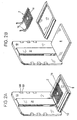
- FIG. 1 shows a side view of the scale 1 with the scale housing 4 and the the draft shield 29 surrounding the weighing room 3.
- the load cell 15 is for Force transmission
- an L-shaped bracket 30 connected to the calibration device 5
- a support 6 for the calibration weights 7 in the lower region of the jib 30 is provided in the left part of the balance housing 4
- the calibration device 5 is located in a top through the Floor 8 of the weighing room 3 completed part of the scale housing 4.
- Am vertical part of the L-shaped bracket 30 are 3 extensions towards the weighing room 31 attached through the bushings 12 of the rear wall 13 of the weighing room 3 protruding. These extensions 31 form with the laterally protruding retaining bolts 22 Coupling arrangement 11 for the mountings 10 of the carrier 2.
- the carrier 2 serves as Support for a wide variety of articles for different applications, for example for dishes, laboratory vessels, other containers for weighing goods or for Weighed goods themselves.
- the carrier 2 is designed as a flat grid 16. Using a grid reduces the possibility of incorrect measurements causing wind influence, since the surface of a grille is less than that of a full-area beam.
- the carrier 2 has a center for receiving the goods to be weighed.
- the center of gravity of the calibration weights 7 is preferably on the Axis 14 which passes through this center (here: through extends the center of gravity of the carrier plane 9). Due to the fact that the bottom 8 does not require passage for moving parts of the scale makes, is a drip tray 17 between the bottom 8 and the carrier 2 closed area provided. Spilled goods fall into the Collection tray 17 and can not be accidentally weighed. This is especially given when the bars of the grid 16 in a special Embodiment a triangular cross section tapering to the top exhibit. This system is also easy to clean.
- a holding system 21 is provided in the interior of the weighing room 3.
- This support system 21 offers a variety of facilities and applications for weighing operation, as described in more detail below.
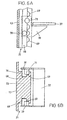
- FIG. 2A shows a perspective view into the weighing room 3 without a windbreak 29.
- the scale housing 4 are just the rear wall 13 of the weighing room 4 and the parts forming the weighing room floor 8 are shown.
- the carrier is 2 hooked in and the drip tray 17 is inserted.
- Figure 2B shows this Arrangement with unhooked carrier 2 and the collecting tray 17 removed.
- FIGS. 3A to 3F show different attachments for different ones Applications in connection with the carrier 2 designed as a grid 16 shown.
- FIG. 3A shows the carrier 2 as a grid 16.
- FIG. 3B shows a contact surface 33 with clip-on edges 32 as a possible form of attachment.
- bowl-shaped receiving attachments 34 for laboratory vessels 35 (FIG. 3C) or circular receiving attachments, ( Figure 3D) or rectangular receiving surfaces, according to Figure 3E.
- the solution in FIG. 3F represents a special application as a grid ring 36
- the grid ring serves as a Faraday cage and acts on electrostatic charges opposite.
- a preferred form of attachment is that by means of those mentioned above clip-on edges 32 or clip-on webs 32 '.
- FIGS. 4A to 4C show a carrier which is in the form of a hanging adapter 49 is designed with a holder 49 '.
- Figure 4A shows a perspective View into weighing room 3 without draft shield 29. Shown is at the Coupling arrangement 11 attached suspension adapter 49 with holder 49 'in one by one perpendicular to the rear wall axis 26 inclined position.
- Figure 4B shows as 4A shows the suspension adapter 49 fastened to the coupling arrangement 11 with holder 49 'in the vertical position.
- the holder 49 ' is from the hanging adapter 49 released and shown in a disassembled state.
- the suspension adapter 49 is suspended in the coupling arrangement 11 in a similar manner as the carrier 2 in Figure 1.
- the hanging adapter 49 has almost semicircular recess 64 in which a spring 50 is arranged.
- a disc 51 provided with a groove 53 is clamped, so that it is rotatable.
- the holder 49 ' is by means of the screw 54 screwed.
- the thus rotatable holder 49 ' has a cup-shaped foot 66 provided and serves, for example, to hold test tubes 65, which by means a height-adjustable bracket 52 can be held.
- the rotatability of the holder 49 'facil itates the addition of substances to be weighed into test tube 65.
- FIG. 5A shows a perspective view of an attachment adapter 49 attached holder 49 "shown. It serves to accommodate several small narrow-necked Vessels 55, for example centrifuge tubes.
- the holder 49 " like that in FIG Figure 4 shown holder 49 ', rotatably mounted about an axis 26' and in the same Designed to be connectable with the hanging adapter 49.
- Figure 5B shows the from the holder 49 "detached adapter 49. Since the filling of powders in the narrow-necked vessels 55 using spatulas the risk of spillage and If the scale is contaminated, it is advantageous to close the narrow-necked vessels 55 Entering substances, for example liquids, using a Multi-channel pipette can be filled into a flat position.
- the scale 1 permits, in particular by means of a on the rear wall 13 arranged holding system 21 for attaching weighing room accessories for example at different heights above the floor 8 Intermediate shelves or brackets, a variety of advantageous applications in the Inside the weighing room 3.
- FIG. 6A One of many possible suspension mechanisms for intermediate floors 37 and / or Brackets in the holding system 21 are shown in FIG. 6A in side view and FIG. 6B on average.
- the holding system 21 is on the rear wall 13 as a columnar projection 23 educated.
- the coupling arrangement 11, on which the carrier 2 is attached arranged (see in Figures 1, 2, 4 and 5).
- the grooves 68 point regularly arranged in the direction of the front of the holding system 21, semicircular recesses 69, into which pin 71 of the suspension device 39 of the intermediate floor 37 or a holder engage positively.
- the compared to the pin 71 to the rear offset pin 70 remain in suspended condition in the grooves 68.
- the pins 71 By slightly lifting the intermediate floor 37 or a holder at the end facing the operator of the scale the pins 71 enter the grooves 68, the pins 70 the tilt axis form.
- the pins 70 and 71 can now in the grooves 68 up or down be moved until the intermediate floor 37 or one is in a horizontal position Hold the pins 71 in one of the semicircular recesses 69 intervene on the right and left on the holding system 21.
- FIG. 7 shows a perspective view of one that can be hooked into the holding system 21 Weighing 79.
- the lift constructed from an L-shaped frame 85 carries the upper one Area a lift motor 80, one of arms 83 and Slats 81 constructed lift platform 89 can raise and lower.
- the slats 81 protrude from below into the spaces between a support 2 designed as a grid 16.
- FIG. 8 shows another embodiment of the weighing elevator 79 'as a cutout in the area of the carrier 82 and the lift platform 89 'shown in side view.
- the means of Coupling arrangement 11 has suspended carriers 82 for receiving the goods to be weighed an adapted grid design in the form of a rake, in which the two lateral boundaries 27 of the carrier 82 on their upper side a sinusoidal Have longitudinal profile, the bars 86 are attached to the crests. Between the bars 86 of the carrier 82, in the valleys of the sinusoidal longitudinal profile are the bars 88 of the lift 79 'in normal weighing below Lattice bars 86 of the carrier 82 and come into a position by lifting the lift 79 ' above the bars 86 of the carrier 82.
- FIG. 9A shows the lift 79 in the weighing position, wherein the vessel 84 to be weighed lies on the support 2 designed as a grid 16 located.
- the slats 81 are lowered.
- Figure 9B shows the rest position.
- the Vessel 84 stands on the raised slats 81.
- the one connected to the scales, Carrier 2 designed as a grid 16 is not loaded.
- the support surface of the lift is through easy to clean the lamellar structure. The same applies to the carrier 2 of the actual scales.
- a useful application of this facility arises for Long-term use of the scale, for example for long-term observation of a Weighing, at which the scales are tared at predefined intervals Trap without a container.
- Also performing a calibration of the Scale for example during the course of long-term use of the scale, is conceivable.
- the container 84 containing the goods to be weighed with the Lift 79, 79 'lifted from carrier 2, 82, calibration weight 7 on support 6 the calibration arrangement 5 applied and weighed, and after calculating and Saving the new data for the calibration of scale 1 will be the goods to be weighed Containing vessel 84 again by lowering the weighing elevator 79, 79 'onto the carrier 2, 82 put on and work can continue.
- Another application of the weighing elevator is also intended for the multiple weighing of a sample to determine statistical quantities, such as the standard deviation, without the operator would have to place the sample by hand or remove it again become.
- the frame 85 of the lift 79, 79 ' is designed in such a way that the holding system 21 also with lift 79, 79 'installed, weighing room accessories, for example a Intermediate floor 37 or a bracket that can be adjusted in height.
- the lift 79, 79 'flexible for further applications.
- the lift 79, 79 'in applications where none Intermediate taring or calibration during ongoing weighing operations is necessary for which Motorized height adjustment of the weighing room accessories that can be attached to the holding system 21; for example, an intermediate floor 37 or a bracket.
- These are then not suspended directly in the holding system 21, but in the lift 79, 79 ', which in turn is in turn attached to the holding system 21.
- the device for code detection 18 can also be attached to the side of the carrier 2, the corresponding code is also attached to the side of the vessel 99.
- the Height-adjustable device for code detection 18 can be suspended in the holding system 21 be designed.
- Turbidity measurements can also be carried out within the weighing room 3 (see FIG 11) by means of a slide-in also inserted at the bottom 8 of the weighing room 3 102 '.
- the insert 102 ' has a bump-like bulge upwards, in which a laser 104 as a transmitter and a photodiode 105 as a receiver.
- the turbidity measurement is carried out in the transmission of a transparent and at the points of the light passage, flat ground measuring vessel 106.
- In the lower area of the Measuring vessel 106 may have a stirrer, for example a magnetic stirrer 107 be driven in the alternating field of the magnets 108.
- the measuring vessel 106 is held by the attachment 110, which is connected to the carrier 2.
Landscapes
- General Physics & Mathematics (AREA)
- Physics & Mathematics (AREA)
- Sampling And Sample Adjustment (AREA)
- Weight Measurement For Supplying Or Discharging Of Specified Amounts Of Material (AREA)
- Measurement Of Force In General (AREA)
- Golf Clubs (AREA)
- Automatic Analysis And Handling Materials Therefor (AREA)
- Devices For Use In Laboratory Experiments (AREA)
- Maintenance And Inspection Apparatuses For Elevators (AREA)
- Investigating Or Analysing Materials By Optical Means (AREA)
- Battery Mounting, Suspending (AREA)
- Refuse-Collection Vehicles (AREA)
- Handcart (AREA)
- Physical Deposition Of Substances That Are Components Of Semiconductor Devices (AREA)
- Analysing Materials By The Use Of Radiation (AREA)
Abstract
Description
- Fig. 1
- eine Seitenansicht der Waage,
- Fig. 2A und 2B
- eine dreidimensionale Darstellung des Wägeraums ohne Waagengehäuse und ohne Windschutz,
- Fig. 3A bis 3F
- Aufsätze für verschiedene Anwendungen auf das als Träger zur Aufnahme des Wägeguts dienende Gitter,
- Fig. 4A bis 4C
- eine andere Ausgestaltung des Trägers zur Aufnahme des Wägeguts in dreidimensionaler Darstellung,
- Fig. 5A und 5B
- eine weitere Ausgestaltung des Trägers zur Aufnahme des Wägeguts in dreidimensionaler Darstellung,
- Fig. 6A und 6B
- die Höhenverstellung des Haltesystems, A in Seitenansicht, B in Draufsicht,
- Fig. 7
- ein Wägelift in dreidimensionaler Darstellung,
- Fig. 8
- eine Plattform des Lifts in einer Gitterausführung mit Träger in der Seitenansicht,
- Fig. 9A und 9B
- die Funktionsweise des Lifts in dreidimensionaler Darstellung,
- Fig. 10
- eine Einrichtung zur Code-Erfassung am Wägegefäss in der Seitenansicht,
- Fig. 11
- eine Einrichtung zur Trübungsmessung des Wägegutes in der Seitenansicht.
- 1
- Waage
- 2
- Träger
- 3
- Wägeraum
- 4
- Waagengehäuse
- 5
- Kalibriervorrichtung
- 6
- Auflage
- 7
- Kalibriergewicht
- 8
- Boden
- 9
- Trägerebene
- 10
- Einhängung
- 11
- Koppelanordnung
- 12
- Durchführungen
- 13
- Rückwand
- 14
- Achse
- 15
- Wägezelle
- 16
- Gitter
- 17
- Auffangschale
- 18
- Einrichtung zur Codeerfassung
- 19
- Code
- 21
- Haltesystem
- 22
- Haltebolzen
- 23
- säulenartiger Vorsprung
- 26
- Achse senkrecht zur Rückwand
- 26'
- Achse
- 27
- seitliche Begrenzungen
- 28
- Glasgefäss
- 29
- Windschutz
- 30
- Ausleger
- 31
- Fortsätze
- 32
- aufklippbare Ränder
- 32'
- aufklippbare Stege
- 33
- Auflagefläche
- 34
- Aufnahmeaufsatz
- 35
- Laborgefäss
- 36
- Gitterring
- 37
- Zwischenboden
- 38
- Laborgefäss
- 49
- Einhäng-Adapter
- 49'
- Halter
- 49"
- Halter
- 50
- Feder
- 51
- Scheibe
- 52
- Klammer
- 53
- Rille
- 54
- Schraube
- 55
- enghalsige Gefässe
- 64
- Aussparung
- 65
- Reagenzglas
- 66
- Fuss
- 68
- Nut
- 69
- halbkreisförmige Aussparung
- 70
- Zapfen
- 71
- Zapfen
- 79
- Lift
- 79'
- Lift
- 80
- Lift-Motor
- 81
- Lamellen
- 82
- Träger
- 83
- Arme
- 84
- Gefäss
- 85
- Gestell
- 86
- Gitterstäbe des Trägers
- 88
- Gitterstäbe des Lifts
- 89
- Liftplattform
- 89'
- Liftplattform
- 98
- Auflage
- 99
- Gefäss
- 100
- Durchführungen
- 101
- Clips
- 102
- Einschub
- 102'
- Einschub
- 103
- Sensorgehäuse
- 104
- Laser
- 105
- Photodiode
- 106
- Messgefäss
- 107
- Magnetrührer
- 108
- Magnete
- 109
- Substanz
- 110
- Befestigung
Claims (24)
- Waage (1) mit einem Wägeraum (3), einem eine Wägezelle (15) enthaltenden, die Rückwand (13) und den Boden (8) des Wägeraums (3) bildenden Waagengehäuse (4) und einem Träger (2) zur Aufnahme von Wägegut an einem mit einer Auflage (6) für Kalibriergewichte (7) einer Kalibriervorrichtung (5) versehenen Ausleger (30) der Wägezelle (15), dadurch gekennzeichnet, dass der Ausleger (30) eine durch Durchführungen (12) in der Rückwand (13) des Wägeraums (3) reichende Koppelanordnung (11) aufweist, mittels welcher der Träger (2) abnehmbar angebracht ist, und sich der Boden (8) geschlossen zwischen der Auflage (6) für Kalibriergewichte (7) und dem Träger (2) erstreckt.
- Waage (1) nach Anspruch 1, dadurch gekennzeichnet, dass der Träger (2) einen Mittelpunkt für die Aufnahme des Wägeguts aufweist und dieser bei aufgebrachtem Wägegut vertikal über dem Gewichtsschwerpunkt der Kalibriergewichte (7) liegt.
- Waage (1) nach Anspruch 1 oder 2, dadurch gekennzeichnet, dass der Träger (2) als ebenes Gitter (16) ausgebildet ist.
- Waage (1) nach Anspruch 3, dadurch gekennzeichnet, dass die Gitterstäbe des Gitters (16) einen nach oben spitz zulaufenden Querschnitt aufweisen.
- Waage (1) nach Anspruch 3 oder 4, dadurch gekennzeichnet, dass verschiedene Aufsätze (33, 34) zur Aufnahme von Wägegefässen am Gitter (16) befestigbar sind.
- Waage (1) nach Anspruch 1 oder 2, dadurch gekennzeichnet, dass der Träger (2) als Halter (49', 49") für ein oder mehrere Laborgefässe (55, 65) ausgebildet ist.
- Waage (1) nach Anspruch 6, dadurch gekennzeichnet, dass der Halter (49', 49") schwenkbar ist.
- Waage (1) nach einem der Ansprüche 1 bis 7, dadurch gekennzeichnet, dass zwischen Träger (2) und Boden (8) eine feste oder herausnehmbare Auffangschale (17) mit geschlossener Fläche angeordnet ist.
- Waage (1) nach einem der Ansprüche 1 bis 8, dadurch gekennzeichnet, dass an der Rückwand (13) des Wägeraums (3) ein festes Haltesystem (21) für das Befestigen von Wägeraum-Zubehör auf verschiedenen Höhen über dem Boden (8) angeordnet ist.
- Waage (1) nach Anspruch 9, dadurch gekennzeichnet, dass das Haltesystem (21) zwei parallel zur Rückwand (13) vertikal verlaufende Nuten (68) aufweist.
- Waage (1) nach Anspruch 10, dadurch gekennzeichnet, dass entlang der Rückwand (13) ein säulenartiger Vorsprung (23) verläuft und die Nuten (68) seitlich in diesem Vorsprung (23) verlaufen.
- Waage (1) nach Anspruch 10 oder 11, dadurch gekennzeichnet, dass die Durchführungen (12) im wesentlichen in der Flucht der Nuten (68) angeordnet sind.
- Waage (1) nach einem der Ansprüche 1 bis 12, dadurch gekennzeichnet, dass im Wägeraum (3) am Waagengehäuse (4) ein Wägelift (79, 79') anbringbar ist.
- Waage (1) nach Anspruch 13, dadurch gekennzeichnet, dass der Wägelift (79) eine gitterförmige, aus Lamellen (81) bestehende Liftplattform (89) aufweist und der Träger (2) als ebenes Gitter (16) ausgebildet ist, wobei die Lamellen (81) des Wägelifts (79) in das Gitter (16) des Trägers (2) in der Weise eingreifbar angeordnet sind, dass das Wägegut vom Träger mittels der Lamellen (81) abgehoben werden kann.
- Waage (1) nach Anspruch 13, dadurch gekennzeichnet, dass sowohl der Träger (82) als auch die Liftplattform (89') als ebenes Gitter ausgebildet sind, wobei die Gitterstäbe der Liftplattform (89') zwischen den Gitterstäben des Trägers in der Weise eingreifbar angeordnet sind, dass das Wägegut vom Träger mittels der Liftplattform (89) abgehoben werden kann.
- Waage (1) nach einem der Ansprüche 13 bis 15, dadurch gekennzeichnet, dass ein Motor (80) vorhanden ist zum motorischen Betrieb des Wägelifts (79, 79').
- Waage (1) nach einem der Ansprüche 1 bis 16, dadurch gekennzeichnet, dass am Boden (8) des Wägeraums (3) ein Einschub (102) anbringbar ist, der eine Einrichtung zur Codeerfassung (18) enthält, wobei ein zu erfassender Code (19) am Boden eines Wägegutgefässes (99) angebracht ist.
- Waage (1) nach einem der Ansprüche 9 bis 16, dadurch gekennzeichnet, dass am Haltesystem (21) eine Einrichtung zur Codeerfassung (18) höhenverstellbar anbringbar ist, wobei ein zu erfassender Code an der Seite des Gefässes (99) für das Wägegut angebracht ist.
- Waage (1) nach Anspruch 17 oder 18, dadurch gekennzeichnet, dass die Codeerfassung optisch erfolgt.
- Waage (1) nach Anspruch 17 oder 18, dadurch gekennzeichnet, dass die Codeerfassung induktiv erfolgt.
- Waage (1) nach einem der Ansprüche 1 bis 20, dadurch gekennzeichnet, dass am Boden (8) des Wägeraums (3) ein Einschub (102') anbringbar ist, der eine Einrichtung zur Messung der Trübung (104, 105) des Wägeguts enthält.
- Waage (1) nach einem der Ansprüche 1 bis 21, dadurch gekennzeichnet, dass am Boden (8) des Wägeraums eine Einrichtung zum Rühren (107, 108) in einem Messgefäss (106) vorhanden ist.
- Verfahren zum Kalibrieren einer Waage (1) während eines Wägevorgangs mit einer Vorrichtung nach den Ansprüchen 13, dadurch gekennzeichnet, dass das das Wägegut enthaltende Gefäss (84) mit dem Wägelift (79, 79') vom Träger (2, 82) abgehoben wird, das Kalibriergewicht (7) auf die Auflage (6) der Kalibrieranordnung (5) aufgebracht und gewogen wird, und nach Berechnen und Abspeichern der neuen Daten für die Kalibration der Waage (1) das das Wägegut enthaltende Gefäss (84) wieder durch Absenken des Wägelifts (79, 79') auf den Träger (2, 82) aufgesetzt wird.
- Verfahren nach Anspruch 23, dadurch gekennzeichnet, dass die Kalibrierung der Waage (1) während einer Langzeitanwendung der Waage (1) mindestens einmal durchgeführt wird.
Priority Applications (1)
| Application Number | Priority Date | Filing Date | Title |
|---|---|---|---|
| EP02102703.2A EP1312900B1 (de) | 2000-10-04 | 2001-09-24 | Waage mit Träger für das Wägegut |
Applications Claiming Priority (2)
| Application Number | Priority Date | Filing Date | Title |
|---|---|---|---|
| CH19572000 | 2000-10-04 | ||
| CH19572000 | 2000-10-04 |
Related Child Applications (1)
| Application Number | Title | Priority Date | Filing Date |
|---|---|---|---|
| EP02102703.2A Division EP1312900B1 (de) | 2000-10-04 | 2001-09-24 | Waage mit Träger für das Wägegut |
Publications (2)
| Publication Number | Publication Date |
|---|---|
| EP1195586A1 true EP1195586A1 (de) | 2002-04-10 |
| EP1195586B1 EP1195586B1 (de) | 2003-04-16 |
Family
ID=4566914
Family Applications (3)
| Application Number | Title | Priority Date | Filing Date |
|---|---|---|---|
| EP01203641A Expired - Lifetime EP1195586B1 (de) | 2000-10-04 | 2001-09-24 | Waage mit Träger für das Wägegut und Kalibriervorrichtung |
| EP02102703.2A Expired - Lifetime EP1312900B1 (de) | 2000-10-04 | 2001-09-24 | Waage mit Träger für das Wägegut |
| EP01203642A Expired - Lifetime EP1195584B1 (de) | 2000-10-04 | 2001-09-24 | Waage mit Wägeraumeinrichtung |
Family Applications After (2)
| Application Number | Title | Priority Date | Filing Date |
|---|---|---|---|
| EP02102703.2A Expired - Lifetime EP1312900B1 (de) | 2000-10-04 | 2001-09-24 | Waage mit Träger für das Wägegut |
| EP01203642A Expired - Lifetime EP1195584B1 (de) | 2000-10-04 | 2001-09-24 | Waage mit Wägeraumeinrichtung |
Country Status (7)
| Country | Link |
|---|---|
| US (3) | US6603081B2 (de) |
| EP (3) | EP1195586B1 (de) |
| JP (3) | JP4163864B2 (de) |
| CN (3) | CN1191459C (de) |
| AT (2) | ATE310233T1 (de) |
| DE (2) | DE50108070D1 (de) |
| HK (3) | HK1046546B (de) |
Cited By (1)
| Publication number | Priority date | Publication date | Assignee | Title |
|---|---|---|---|---|
| EP3865834A1 (de) | 2020-02-11 | 2021-08-18 | Mettler-Toledo GmbH | Windschutzstruktur für eine lastaufnahmeanordnung in einer waage |
Families Citing this family (71)
| Publication number | Priority date | Publication date | Assignee | Title |
|---|---|---|---|---|
| NL1015439C2 (nl) * | 2000-06-14 | 2001-12-17 | E H Klijn Beheer B V | Doseerinrichting. |
| US6603081B2 (en) * | 2000-10-04 | 2003-08-05 | Mettler-Toledo Gmbh | Balance with a weighing compartment |
| DE10157804B4 (de) * | 2001-11-27 | 2014-04-24 | Mettler-Toledo Ag | Gewichtssatz für eine elektronische Waage |
| DE10158179B4 (de) * | 2001-11-28 | 2014-04-24 | Mettler-Toledo Ag | Probenwechsler für eine Waage |
| DE10214755B4 (de) * | 2002-04-03 | 2004-07-15 | Mettler-Toledo Gmbh | Waage mit einem Trägerelement zur Ankopplung einer Waagschale an eine Wägezelle |
| EP1367372B1 (de) * | 2002-05-29 | 2005-11-23 | Mettler-Toledo GmbH | Windschutzvorrichtung für eine Waage und Waage mit Windschutz |
| US7114368B2 (en) * | 2003-04-08 | 2006-10-03 | Abbott Laboratories | Apparatus and method for verifying the volume of liquid dispensed by a liquid-dispensing mechanism |
| JP4203737B2 (ja) * | 2003-07-28 | 2009-01-07 | 株式会社島津製作所 | ロードセル式重量測定装置 |
| PL1674840T3 (pl) * | 2004-12-23 | 2009-07-31 | Mettler Toledo Gmbh | Układ dozujący w wadze |
| US8066759B2 (en) * | 2005-02-04 | 2011-11-29 | Boston Scientific Scimed, Inc. | Resonator for medical device |
| ATE514058T1 (de) * | 2005-04-19 | 2011-07-15 | Mettler Toledo Ag | Waage mit einem windschutz |
| WO2006132235A1 (ja) * | 2005-06-07 | 2006-12-14 | Shimadzu Corporation | ロードセル式電子天びん |
| US7279664B2 (en) * | 2005-07-26 | 2007-10-09 | Boston Scientific Scimed, Inc. | Resonator for medical device |
| US7304277B2 (en) * | 2005-08-23 | 2007-12-04 | Boston Scientific Scimed, Inc | Resonator with adjustable capacitor for medical device |
| US7524282B2 (en) * | 2005-08-29 | 2009-04-28 | Boston Scientific Scimed, Inc. | Cardiac sleeve apparatus, system and method of use |
| US7441436B2 (en) * | 2005-09-27 | 2008-10-28 | Mettler-Toledo, Inc. | Method for weighing apparatus calibration management |
| AU2006302462A1 (en) * | 2005-10-05 | 2007-04-19 | Bell Helicopter Textron Inc. | Integrated aircraft scale and leveling apparatus and methods for use |
| US7423496B2 (en) * | 2005-11-09 | 2008-09-09 | Boston Scientific Scimed, Inc. | Resonator with adjustable capacitance for medical device |
| EP1850110A1 (de) * | 2006-04-25 | 2007-10-31 | Mettler-Toledo AG | Messgerät zur gravimetrischen Feuchtigkeitsbestimmung |
| DE502006009215D1 (de) * | 2006-10-11 | 2011-05-12 | Mettler Toledo Ag | Elektronische Waage |
| US7560651B2 (en) * | 2006-10-11 | 2009-07-14 | Mettler-Toledo Ag | Electronic balance |
| EP1912046A1 (de) * | 2006-10-11 | 2008-04-16 | Mettler-Toledo AG | Messgerät zur gravimetrischen Feuchtigkeitsbestimmung |
| US20080257612A1 (en) * | 2007-03-07 | 2008-10-23 | Eternal Voyage Inc. | Scale accessory |
| US20080245580A1 (en) * | 2007-04-05 | 2008-10-09 | Aby-Eva Gregoire B | Scale including a removable display |
| US7606625B2 (en) | 2007-06-15 | 2009-10-20 | Abbott Cardiovascular Systems Inc. | Method and device for aligning a stent with a stent support |
| US7885788B2 (en) | 2007-06-15 | 2011-02-08 | Abbott Cardiovascular Systems Inc. | Method and apparatus for weighing a stent |
| EP2170416B1 (de) * | 2007-06-15 | 2016-03-16 | Abbott Cardiovascular Systems Inc. | System und verfahren zum wiegen eines stents |
| US7897195B2 (en) | 2007-06-15 | 2011-03-01 | Abbott Cardiovascular Systems Inc. | Devices for coating stents |
| US7812941B2 (en) | 2007-06-15 | 2010-10-12 | Abbott Cardiovascular Systems Inc. | Systems and methods for the inspection of cylinders |
| US8677650B2 (en) | 2007-06-15 | 2014-03-25 | Abbott Cardiovascular Systems Inc. | Methods and devices for drying coated stents |
| US8003157B2 (en) | 2007-06-15 | 2011-08-23 | Abbott Cardiovascular Systems Inc. | System and method for coating a stent |
| GB0719469D0 (en) * | 2007-10-04 | 2007-11-14 | Metryx Ltd | Measurement apparatus and method |
| EP2060885A1 (de) * | 2007-11-19 | 2009-05-20 | Mettler-Toledo AG | Laborgerät mit einem geschützten arbeitsraum |
| DE102008029901B4 (de) * | 2008-06-24 | 2010-10-28 | Ika-Werke Gmbh & Co. Kg | Magnetrührer mit Aufstellfüßen |
| EP2163867B1 (de) * | 2008-09-11 | 2014-09-10 | Mettler-Toledo AG | Einwaagegefäss zum Einwägen von Substanzen |
| DE102008062144A1 (de) * | 2008-12-16 | 2010-06-17 | Mettler-Toledo Ag | Lastträger |
| PL2207019T3 (pl) | 2009-01-08 | 2019-08-30 | Mettler-Toledo Gmbh | Nośnik ważonego materiału do wagi |
| EP2251657B1 (de) * | 2009-05-13 | 2012-11-28 | Mettler-Toledo AG | Windschutzvorrichtung für ein Laborgerät |
| EP2259032B1 (de) * | 2009-05-13 | 2013-06-19 | Mettler-Toledo AG | Windschutzvorrichtung für ein Laborgerät |
| US8567340B2 (en) | 2009-08-12 | 2013-10-29 | Abbott Cardiovascular Systems Inc. | System and method for coating a medical device |
| PL2388561T3 (pl) * | 2010-05-20 | 2016-05-31 | Mettler Toledo Gmbh | Urządzenie laboratoryjne do przygotowywania próbek |
| JP5448090B2 (ja) * | 2010-06-17 | 2014-03-19 | 株式会社エー・アンド・デイ | 計量室を有する秤量装置 |
| DE102011000429B4 (de) * | 2011-02-01 | 2015-08-06 | Sartorius Lab Instruments Gmbh & Co. Kg | Wägekabine mit integrierter Waage |
| CN102798451A (zh) * | 2012-08-03 | 2012-11-28 | 昆山旭虹精密零组件有限公司 | 一种可拆卸电子天平 |
| WO2014023439A1 (de) * | 2012-08-10 | 2014-02-13 | Siemens Aktiengesellschaft | Mess- und schutzvorrichtung für beschichtungsprozesse |
| US9018545B2 (en) * | 2012-09-28 | 2015-04-28 | Symbol Technologies, Inc. | Arrangement for and method of preventing overhanging weighing platter of scale from tipping at product checkout system and method of mounting and removing the weighing platter without tools |
| DE102013010203B4 (de) * | 2013-06-15 | 2022-06-30 | Ika-Werke Gmbh & Co. Kg | Labor-Stativ mit wenigstens einer Haltestange und einer diese tragenden Bodenabstützung mit Aufstellfüßen |
| US9389135B2 (en) * | 2013-09-26 | 2016-07-12 | WD Media, LLC | Systems and methods for calibrating a load cell of a disk burnishing machine |
| CN103471697A (zh) * | 2013-09-30 | 2013-12-25 | 南京白云化工环境监测有限公司 | 一种可进行水平校准的电子分析天平 |
| PL2860501T3 (pl) | 2013-10-10 | 2017-05-31 | Mettler-Toledo Gmbh | Ogniwo obciążnikowe z urządzeniem do korygowania błędów obciążenia mimośrodowego i sposób korygowania błędów obciążenia mimośrodowego |
| DE102014101565A1 (de) * | 2013-11-08 | 2015-05-13 | Sartorius Lab Instruments Gmbh & Co. Kg | Komparatorwaage mit abnehmbarem Klimamodul |
| FR3017706B1 (fr) * | 2014-02-18 | 2017-11-03 | Interscience | Dispositif de distribution gravimetrique |
| EP2924401B1 (de) * | 2014-03-28 | 2016-12-28 | Mettler-Toledo GmbH | Roboterbetätigte Türöffnungsvorrichtung für ein Windschutzgehäuse einer Analysenwaage |
| DE102015103772B4 (de) * | 2015-03-15 | 2020-10-22 | Waldner Ag | Wägeabzug |
| CN105222871B (zh) * | 2015-09-29 | 2018-03-06 | 慈溪市天域电子科技有限公司 | 厨房用电子秤装置 |
| CN105222876B (zh) * | 2015-09-29 | 2017-12-15 | 慈溪市天域电子科技有限公司 | 一种可下料式厨房用电子称 |
| ES2827791T3 (es) * | 2016-03-15 | 2021-05-24 | Fresenius Kabi Deutschland Gmbh | Balanza e instalación para fabricar una preparación medicinal |
| US10736612B2 (en) * | 2016-12-14 | 2020-08-11 | Boka Sciences, Inc. | Salvia assessing method, device, and system |
| EP3557201B1 (de) * | 2018-04-17 | 2021-09-29 | Mettler-Toledo GmbH | Laborwaage mit motorisch verstellbarer oberer windschutzwand |
| PL3557198T3 (pl) * | 2018-04-17 | 2021-05-31 | Mettler-Toledo Gmbh | Waga laboratoryjna z szalką mocowaną wspornikowo |
| EP3578935B1 (de) * | 2018-06-07 | 2021-03-31 | Mettler-Toledo GmbH | Wiegevorrichtung mit beweglicher halterung |
| DE102019102805B4 (de) | 2019-02-05 | 2021-07-15 | Sartorius Lab Instruments Gmbh & Co. Kg | Gravimetrisches Messsystem |
| DE102019102810B8 (de) | 2019-02-05 | 2021-07-15 | Sartorius Lab Instruments Gmbh & Co. Kg | Gravimetrisches Messsystem |
| DE102019102811B4 (de) | 2019-02-05 | 2021-07-15 | Sartorius Lab Instruments Gmbh & Co. Kg | Gravimetrisches Messsystem |
| DE102019102801B8 (de) | 2019-02-05 | 2021-07-15 | Sartorius Lab Instruments Gmbh & Co. Kg | Gravimetrisches Messsystem |
| PL3705858T3 (pl) * | 2019-03-07 | 2022-01-31 | Mettler-Toledo Gmbh | Waga wyposażona w zespół mocujący do przenoszenia wymiennych elementów wyposażenia |
| EP3852031A1 (de) * | 2020-01-20 | 2021-07-21 | Accenture Global Solutions Limited | System zur erfassung der nachgiebigkeit eines behälters |
| DE102020110865A1 (de) | 2020-04-22 | 2021-10-28 | Sartorius Lab Instruments Gmbh & Co. Kg | Gravimetrische Messvorrichtung |
| JP2022130219A (ja) * | 2021-02-25 | 2022-09-06 | 株式会社島津製作所 | 電子天びん |
| CN116027060A (zh) * | 2022-06-29 | 2023-04-28 | 深圳晶泰科技有限公司 | 一种粉末加样设备及粉末加样系统 |
| CN116295748B (zh) * | 2023-05-17 | 2023-08-18 | 时新(上海)产品设计有限公司 | 分配计量装置 |
Citations (5)
| Publication number | Priority date | Publication date | Assignee | Title |
|---|---|---|---|---|
| US4156361A (en) * | 1976-01-14 | 1979-05-29 | Sartorius-Werke Gmbh | Calibratable electromagnetically compensating balance |
| US4425975A (en) * | 1981-04-10 | 1984-01-17 | Mettler Instrumente Ag | Weighing apparatus including calibrating weight operating means |
| US4566548A (en) * | 1983-08-27 | 1986-01-28 | Sartorius Gmbh | Analytical balance |
| US4932487A (en) * | 1988-05-07 | 1990-06-12 | Sartorius Gmbh | Electronic balance with calibrating weight circuit |
| US5148881A (en) * | 1990-07-27 | 1992-09-22 | Mettler - Toledo Ag | Electronic weighting apparatus with calibration weight arrangement |
Family Cites Families (22)
| Publication number | Priority date | Publication date | Assignee | Title |
|---|---|---|---|---|
| US2490131A (en) * | 1947-05-15 | 1949-12-06 | United Air Lines Inc | Article handling and weighing apparatus |
| FR2310553A1 (fr) * | 1975-05-05 | 1976-12-03 | Automatisme Cie Gle | Dispositif d'acheminement et de pesage d'objets |
| JPS6053276B2 (ja) * | 1982-06-28 | 1985-11-25 | 株式会社神戸製鋼所 | ロ−タリ−キルン内診断方法 |
| GB2174498B (en) * | 1985-04-18 | 1989-04-19 | Yamato Scale Co Ltd | Mass meter |
| US4682664A (en) * | 1985-07-31 | 1987-07-28 | Canadian Corporate Management Co., Ltd. | Load sensing systems for conveyor weigh scales |
| DE3610560A1 (de) | 1986-03-27 | 1987-10-01 | Heinz Leutheuser | Fussfoen |
| JP2527308B2 (ja) * | 1986-05-15 | 1996-08-21 | 株式会社エー・アンド・デイ | 気流による影響を防止した秤量装置 |
| CH671102A5 (de) * | 1986-12-16 | 1989-07-31 | Mettler Instrumente Ag | |
| US4789033A (en) * | 1987-09-28 | 1988-12-06 | Dohrmann David K | Onboard weight indicator for vehicles |
| FR2625315B1 (fr) * | 1987-12-24 | 1991-04-26 | Largenton Jean Luc | Dispositif pour le pesage de vehicules |
| JPH07899Y2 (ja) * | 1988-09-13 | 1995-01-11 | 東京電気株式会社 | ロードセル秤 |
| CH677279A5 (de) | 1988-11-29 | 1991-04-30 | Mettler Toledo Ag | |
| DE9203744U1 (de) | 1992-03-20 | 1993-07-15 | Sartorius Ag, 3400 Goettingen, De | |
| US5641841A (en) * | 1995-01-10 | 1997-06-24 | International Business Machines Corporation | Conductive lubricant for magnetic disk drives |
| JP3164760B2 (ja) * | 1996-02-29 | 2001-05-08 | 株式会社クボタ | ロードセル式台はかり |
| JPH1165950A (ja) * | 1997-08-15 | 1999-03-09 | Sony Corp | 情報通信方法、情報通信システム、携帯無線通信端末およびサーバ装置 |
| EP0897104A1 (de) | 1997-08-14 | 1999-02-17 | Busch-Werke AG | Lastträger für Wägevorrichtung |
| DE29912867U1 (de) * | 1998-11-05 | 2000-03-30 | Sartorius Gmbh | Analysenwaage mit zusätzlichem Messwertaufnehmer für Umgebungsparameter |
| CH694475A5 (de) * | 1999-07-08 | 2005-01-31 | Mettler Toledo Gmbh | Verfahren zum Betrieb einer Waage und Vorrichtung zur Durchführung des Verfahrens. |
| US6603081B2 (en) * | 2000-10-04 | 2003-08-05 | Mettler-Toledo Gmbh | Balance with a weighing compartment |
| US6686545B2 (en) * | 2000-10-04 | 2004-02-03 | Mettler-Toledo Gmbh | Balance with a weighing compartment |
| DE10214755B4 (de) * | 2002-04-03 | 2004-07-15 | Mettler-Toledo Gmbh | Waage mit einem Trägerelement zur Ankopplung einer Waagschale an eine Wägezelle |
-
2001
- 2001-09-21 US US09/957,934 patent/US6603081B2/en not_active Expired - Lifetime
- 2001-09-21 US US09/957,977 patent/US6557391B2/en not_active Expired - Lifetime
- 2001-09-24 AT AT01203642T patent/ATE310233T1/de not_active IP Right Cessation
- 2001-09-24 EP EP01203641A patent/EP1195586B1/de not_active Expired - Lifetime
- 2001-09-24 EP EP02102703.2A patent/EP1312900B1/de not_active Expired - Lifetime
- 2001-09-24 AT AT01203641T patent/ATE237800T1/de not_active IP Right Cessation
- 2001-09-24 DE DE50108070T patent/DE50108070D1/de not_active Expired - Lifetime
- 2001-09-24 EP EP01203642A patent/EP1195584B1/de not_active Expired - Lifetime
- 2001-09-24 DE DE50100174T patent/DE50100174D1/de not_active Expired - Lifetime
- 2001-09-27 JP JP2001295319A patent/JP4163864B2/ja not_active Expired - Fee Related
- 2001-09-27 JP JP2001295361A patent/JP4230687B2/ja not_active Expired - Lifetime
- 2001-09-29 CN CNB011360798A patent/CN1191459C/zh not_active Expired - Lifetime
- 2001-09-29 CN CNB2005100046082A patent/CN100335875C/zh not_active Expired - Lifetime
- 2001-09-29 CN CNB01136078XA patent/CN1192220C/zh not_active Expired - Lifetime
-
2002
- 2002-10-31 HK HK02107930.6A patent/HK1046546B/zh not_active IP Right Cessation
- 2002-10-31 HK HK02107931.5A patent/HK1046547B/zh not_active IP Right Cessation
-
2003
- 2003-01-31 US US10/355,935 patent/US6835901B2/en not_active Expired - Lifetime
-
2006
- 2006-01-04 HK HK06100152.8A patent/HK1080140A1/zh unknown
-
2007
- 2007-08-22 JP JP2007216196A patent/JP4688852B2/ja not_active Expired - Lifetime
Patent Citations (5)
| Publication number | Priority date | Publication date | Assignee | Title |
|---|---|---|---|---|
| US4156361A (en) * | 1976-01-14 | 1979-05-29 | Sartorius-Werke Gmbh | Calibratable electromagnetically compensating balance |
| US4425975A (en) * | 1981-04-10 | 1984-01-17 | Mettler Instrumente Ag | Weighing apparatus including calibrating weight operating means |
| US4566548A (en) * | 1983-08-27 | 1986-01-28 | Sartorius Gmbh | Analytical balance |
| US4932487A (en) * | 1988-05-07 | 1990-06-12 | Sartorius Gmbh | Electronic balance with calibrating weight circuit |
| US5148881A (en) * | 1990-07-27 | 1992-09-22 | Mettler - Toledo Ag | Electronic weighting apparatus with calibration weight arrangement |
Cited By (1)
| Publication number | Priority date | Publication date | Assignee | Title |
|---|---|---|---|---|
| EP3865834A1 (de) | 2020-02-11 | 2021-08-18 | Mettler-Toledo GmbH | Windschutzstruktur für eine lastaufnahmeanordnung in einer waage |
Also Published As
| Publication number | Publication date |
|---|---|
| US20020040815A1 (en) | 2002-04-11 |
| US6835901B2 (en) | 2004-12-28 |
| HK1046547A1 (en) | 2003-01-17 |
| EP1312900B1 (de) | 2015-05-27 |
| DE50108070D1 (de) | 2005-12-22 |
| HK1046546A1 (en) | 2003-01-17 |
| EP1312900A1 (de) | 2003-05-21 |
| US20030115929A1 (en) | 2003-06-26 |
| CN1192220C (zh) | 2005-03-09 |
| US20020038567A1 (en) | 2002-04-04 |
| JP2002181616A (ja) | 2002-06-26 |
| DE50100174D1 (de) | 2003-05-22 |
| CN1346971A (zh) | 2002-05-01 |
| HK1080140A1 (zh) | 2006-04-21 |
| HK1046546B (zh) | 2005-10-21 |
| ATE237800T1 (de) | 2003-05-15 |
| ATE310233T1 (de) | 2005-12-15 |
| US6557391B2 (en) | 2003-05-06 |
| EP1195584B1 (de) | 2005-11-16 |
| JP4230687B2 (ja) | 2009-02-25 |
| CN1191459C (zh) | 2005-03-02 |
| US6603081B2 (en) | 2003-08-05 |
| CN100335875C (zh) | 2007-09-05 |
| JP4163864B2 (ja) | 2008-10-08 |
| JP2007333747A (ja) | 2007-12-27 |
| JP4688852B2 (ja) | 2011-05-25 |
| CN1654932A (zh) | 2005-08-17 |
| CN1346970A (zh) | 2002-05-01 |
| JP2002195873A (ja) | 2002-07-10 |
| HK1046547B (zh) | 2005-10-07 |
| EP1195584A1 (de) | 2002-04-10 |
| EP1195586B1 (de) | 2003-04-16 |
Similar Documents
| Publication | Publication Date | Title |
|---|---|---|
| EP1195586B1 (de) | Waage mit Träger für das Wägegut und Kalibriervorrichtung | |
| EP1715312B1 (de) | Waage mit einem Windschutz | |
| DE10100984B4 (de) | Vorrichtung für die Kalibrierung von Mehrkanal-Pipetten mittels Vorrichtung für den Transport von Gefässen zu einer Messeinrichtung | |
| EP2259032B1 (de) | Windschutzvorrichtung für ein Laborgerät | |
| EP1092473A2 (de) | Vorrichtung zur gravimetrischen Prüfung von Mehrkanalpipetten | |
| EP2446959B1 (de) | Probenmischvorrichtung | |
| DE202018105715U1 (de) | Dosieranlage zur Herstellung einer benutzerdefinierten Formulierung durch Dosieren von flüssigen Produkten mit Halterung zum lösbaren Halten der Farbtoneinheiten | |
| EP1674840B1 (de) | Abfüllsystem in einer Waage | |
| EP3442499A1 (de) | Waage und anlage zur herstellung einer medizinischen zubereitung | |
| EP0292866A2 (de) | Vorrichtung zum gewichtsmässigen Erfassen von Material, vorzugsweise Müll, an einem Sammelfahrzeug | |
| EP0371210A2 (de) | Gefässhalter für Präzisionswaagen und Analysenwaagen | |
| DE3618707A1 (de) | Verfahren und vorrichtung zur korngroessenanalyse | |
| DE10158179B4 (de) | Probenwechsler für eine Waage | |
| DE2343763A1 (de) | Testprobenhalter fuer ein einsatztablett | |
| EP2359103B1 (de) | Lastträger | |
| WO2015185341A1 (de) | Verfahren zur mikroskopischen abbilding von proben in töpfchen einer mikrotiterplatte | |
| DE102020134572B4 (de) | Milchprobeentnahmevorrichtung mit Abfülleinrichtung | |
| WO1991017832A1 (de) | Objektträger für nasse oder feuchte präparate, z.b. blut | |
| EP1642097A1 (de) | Waage mit windschutzelement | |
| DE102004020373B4 (de) | Messvorrichtung, Wendevorrichtung und Verfahren zum Bestimmen von magnetischen Eigenschaften | |
| DE102017010815A1 (de) | Vorrichtung und Verfahren für die parallele Handhabung, Beobachtung und Kontrolle von gewebeähnlichen Zellverbänden | |
| DE10347341B3 (de) | Oberschalige Waage für unterschiedliche Wägegüter | |
| DE3346003A1 (de) | Wanne oder becken, insbesondere fuer mit hilfe von sogenannten mehrfachpipetten zu pipettierende bzw. zu entnehmende fluessigkeiten | |
| EP3097978A1 (de) | Flüssigkeitsbehälter mit einer schwappschutzvorrichtung | |
| EP3220148B1 (de) | Verfahren zur überwachung des transports von flüssigkeitsbehältern in einem automatischen analysegerät |
Legal Events
| Date | Code | Title | Description |
|---|---|---|---|
| PUAI | Public reference made under article 153(3) epc to a published international application that has entered the european phase |
Free format text: ORIGINAL CODE: 0009012 |
|
| 17P | Request for examination filed |
Effective date: 20010924 |
|
| AK | Designated contracting states |
Kind code of ref document: A1 Designated state(s): AT BE CH CY DE DK ES FI FR GB GR IE IT LI LU MC NL PT SE TR |
|
| AX | Request for extension of the european patent |
Free format text: AL;LT;LV;MK;RO;SI |
|
| GRAH | Despatch of communication of intention to grant a patent |
Free format text: ORIGINAL CODE: EPIDOS IGRA |
|
| GRAH | Despatch of communication of intention to grant a patent |
Free format text: ORIGINAL CODE: EPIDOS IGRA |
|
| GRAH | Despatch of communication of intention to grant a patent |
Free format text: ORIGINAL CODE: EPIDOS IGRA |
|
| AKX | Designation fees paid |
Free format text: AT BE CH CY DE DK ES FI FR GB GR IE IT LI LU MC NL PT SE TR |
|
| GRAA | (expected) grant |
Free format text: ORIGINAL CODE: 0009210 |
|
| AK | Designated contracting states |
Designated state(s): AT BE CH CY DE DK ES FI FR GB GR IE IT LI LU MC NL PT SE TR |
|
| PG25 | Lapsed in a contracting state [announced via postgrant information from national office to epo] |
Ref country code: TR Free format text: LAPSE BECAUSE OF FAILURE TO SUBMIT A TRANSLATION OF THE DESCRIPTION OR TO PAY THE FEE WITHIN THE PRESCRIBED TIME-LIMIT Effective date: 20030416 Ref country code: FI Free format text: LAPSE BECAUSE OF FAILURE TO SUBMIT A TRANSLATION OF THE DESCRIPTION OR TO PAY THE FEE WITHIN THE PRESCRIBED TIME-LIMIT Effective date: 20030416 |
|
| REG | Reference to a national code |
Ref country code: GB Ref legal event code: FG4D Free format text: NOT ENGLISH |
|
| REG | Reference to a national code |
Ref country code: CH Ref legal event code: EP |
|
| REF | Corresponds to: |
Ref document number: 50100174 Country of ref document: DE Date of ref document: 20030522 Kind code of ref document: P |
|
| REG | Reference to a national code |
Ref country code: IE Ref legal event code: FG4D Free format text: GERMAN |
|
| PG25 | Lapsed in a contracting state [announced via postgrant information from national office to epo] |
Ref country code: SE Free format text: LAPSE BECAUSE OF FAILURE TO SUBMIT A TRANSLATION OF THE DESCRIPTION OR TO PAY THE FEE WITHIN THE PRESCRIBED TIME-LIMIT Effective date: 20030716 Ref country code: PT Free format text: LAPSE BECAUSE OF FAILURE TO SUBMIT A TRANSLATION OF THE DESCRIPTION OR TO PAY THE FEE WITHIN THE PRESCRIBED TIME-LIMIT Effective date: 20030716 Ref country code: GR Free format text: LAPSE BECAUSE OF FAILURE TO SUBMIT A TRANSLATION OF THE DESCRIPTION OR TO PAY THE FEE WITHIN THE PRESCRIBED TIME-LIMIT Effective date: 20030716 Ref country code: DK Free format text: LAPSE BECAUSE OF FAILURE TO SUBMIT A TRANSLATION OF THE DESCRIPTION OR TO PAY THE FEE WITHIN THE PRESCRIBED TIME-LIMIT Effective date: 20030716 |
|
| GBT | Gb: translation of ep patent filed (gb section 77(6)(a)/1977) |
Effective date: 20030715 |
|
| PG25 | Lapsed in a contracting state [announced via postgrant information from national office to epo] |
Ref country code: LU Free format text: LAPSE BECAUSE OF NON-PAYMENT OF DUE FEES Effective date: 20030924 Ref country code: CY Free format text: LAPSE BECAUSE OF FAILURE TO SUBMIT A TRANSLATION OF THE DESCRIPTION OR TO PAY THE FEE WITHIN THE PRESCRIBED TIME-LIMIT Effective date: 20030924 |
|
| PG25 | Lapsed in a contracting state [announced via postgrant information from national office to epo] |
Ref country code: MC Free format text: LAPSE BECAUSE OF NON-PAYMENT OF DUE FEES Effective date: 20030930 |
|
| PG25 | Lapsed in a contracting state [announced via postgrant information from national office to epo] |
Ref country code: ES Free format text: LAPSE BECAUSE OF FAILURE TO SUBMIT A TRANSLATION OF THE DESCRIPTION OR TO PAY THE FEE WITHIN THE PRESCRIBED TIME-LIMIT Effective date: 20031030 |
|
| ET | Fr: translation filed | ||
| PLBE | No opposition filed within time limit |
Free format text: ORIGINAL CODE: 0009261 |
|
| STAA | Information on the status of an ep patent application or granted ep patent |
Free format text: STATUS: NO OPPOSITION FILED WITHIN TIME LIMIT |
|
| 26N | No opposition filed |
Effective date: 20040119 |
|
| REG | Reference to a national code |
Ref country code: CH Ref legal event code: PFA Owner name: METTLER-TOLEDO AG Free format text: METTLER-TOLEDO GMBH#IM LANGACHER, P.O. BOX MT-100#8606 GREIFENSEE (CH) -TRANSFER TO- METTLER-TOLEDO AG#IM LANGACHER#8606 GREIFENSEE (CH) |
|
| PGFP | Annual fee paid to national office [announced via postgrant information from national office to epo] |
Ref country code: AT Payment date: 20060914 Year of fee payment: 6 |
|
| PGFP | Annual fee paid to national office [announced via postgrant information from national office to epo] |
Ref country code: BE Payment date: 20061012 Year of fee payment: 6 |
|
| NLS | Nl: assignments of ep-patents |
Owner name: METTLER-TOLEDO AG Effective date: 20060901 |
|
| REG | Reference to a national code |
Ref country code: FR Ref legal event code: CJ Ref country code: FR Ref legal event code: CD |
|
| BERE | Be: lapsed |
Owner name: *METTLER-TOLEDO G.M.B.H. Effective date: 20070930 |
|
| PG25 | Lapsed in a contracting state [announced via postgrant information from national office to epo] |
Ref country code: AT Free format text: LAPSE BECAUSE OF NON-PAYMENT OF DUE FEES Effective date: 20070924 |
|
| PG25 | Lapsed in a contracting state [announced via postgrant information from national office to epo] |
Ref country code: BE Free format text: LAPSE BECAUSE OF NON-PAYMENT OF DUE FEES Effective date: 20070930 |
|
| REG | Reference to a national code |
Ref country code: CH Ref legal event code: PCOW Free format text: NEW ADDRESS: IM LANGACHER 44, 8606 GREIFENSEE (CH) |
|
| REG | Reference to a national code |
Ref country code: CH Ref legal event code: PFA Owner name: METTLER-TOLEDO GMBH, CH Free format text: FORMER OWNER: METTLER-TOLEDO AG, CH |
|
| REG | Reference to a national code |
Ref country code: FR Ref legal event code: PLFP Year of fee payment: 16 |
|
| REG | Reference to a national code |
Ref country code: DE Ref legal event code: R082 Ref document number: 50100174 Country of ref document: DE Representative=s name: LEINWEBER & ZIMMERMANN PATENTANWALTS-PARTG MBB, DE Ref country code: DE Ref legal event code: R082 Ref document number: 50100174 Country of ref document: DE Representative=s name: LEINWEBER & ZIMMERMANN, DE Ref country code: DE Ref legal event code: R081 Ref document number: 50100174 Country of ref document: DE Owner name: METTLER-TOLEDO GMBH, CH Free format text: FORMER OWNER: METTLER-TOLEDO AG, GREIFENSEE, CH |
|
| REG | Reference to a national code |
Ref country code: FR Ref legal event code: PLFP Year of fee payment: 17 |
|
| PGFP | Annual fee paid to national office [announced via postgrant information from national office to epo] |
Ref country code: FR Payment date: 20170823 Year of fee payment: 17 Ref country code: IT Payment date: 20170913 Year of fee payment: 17 |
|
| REG | Reference to a national code |
Ref country code: NL Ref legal event code: PD Owner name: METTLER-TOLEDO GMBH; CH Free format text: DETAILS ASSIGNMENT: CHANGE OF OWNER(S), CHANGE OF LEGAL ENTITY; FORMER OWNER NAME: METTLER-TOLEDO AG Effective date: 20170830 |
|
| PGFP | Annual fee paid to national office [announced via postgrant information from national office to epo] |
Ref country code: NL Payment date: 20170913 Year of fee payment: 17 Ref country code: IE Payment date: 20170918 Year of fee payment: 17 |
|
| REG | Reference to a national code |
Ref country code: FR Ref legal event code: CJ Effective date: 20180409 |
|
| REG | Reference to a national code |
Ref country code: NL Ref legal event code: MM Effective date: 20181001 |
|
| REG | Reference to a national code |
Ref country code: IE Ref legal event code: MM4A |
|
| PG25 | Lapsed in a contracting state [announced via postgrant information from national office to epo] |
Ref country code: NL Free format text: LAPSE BECAUSE OF NON-PAYMENT OF DUE FEES Effective date: 20181001 |
|
| PG25 | Lapsed in a contracting state [announced via postgrant information from national office to epo] |
Ref country code: IT Free format text: LAPSE BECAUSE OF NON-PAYMENT OF DUE FEES Effective date: 20180924 Ref country code: IE Free format text: LAPSE BECAUSE OF NON-PAYMENT OF DUE FEES Effective date: 20180924 |
|
| PG25 | Lapsed in a contracting state [announced via postgrant information from national office to epo] |
Ref country code: FR Free format text: LAPSE BECAUSE OF NON-PAYMENT OF DUE FEES Effective date: 20180930 |
|
| PGFP | Annual fee paid to national office [announced via postgrant information from national office to epo] |
Ref country code: GB Payment date: 20200828 Year of fee payment: 20 Ref country code: DE Payment date: 20200812 Year of fee payment: 20 |
|
| PGFP | Annual fee paid to national office [announced via postgrant information from national office to epo] |
Ref country code: CH Payment date: 20200818 Year of fee payment: 20 |
|
| REG | Reference to a national code |
Ref country code: DE Ref legal event code: R071 Ref document number: 50100174 Country of ref document: DE |
|
| REG | Reference to a national code |
Ref country code: GB Ref legal event code: PE20 Expiry date: 20210923 |
|
| REG | Reference to a national code |
Ref country code: CH Ref legal event code: PL |
|
| PG25 | Lapsed in a contracting state [announced via postgrant information from national office to epo] |
Ref country code: GB Free format text: LAPSE BECAUSE OF EXPIRATION OF PROTECTION Effective date: 20210923 |