EP1204438B1 - Inhaler - Google Patents
Inhaler Download PDFInfo
- Publication number
- EP1204438B1 EP1204438B1 EP00944542A EP00944542A EP1204438B1 EP 1204438 B1 EP1204438 B1 EP 1204438B1 EP 00944542 A EP00944542 A EP 00944542A EP 00944542 A EP00944542 A EP 00944542A EP 1204438 B1 EP1204438 B1 EP 1204438B1
- Authority
- EP
- European Patent Office
- Prior art keywords
- canister
- inhaler
- medicament
- inhalation
- return
- Prior art date
- Legal status (The legal status is an assumption and is not a legal conclusion. Google has not performed a legal analysis and makes no representation as to the accuracy of the status listed.)
- Expired - Lifetime
Links
Images


Classifications
-
- A—HUMAN NECESSITIES
- A61—MEDICAL OR VETERINARY SCIENCE; HYGIENE
- A61M—DEVICES FOR INTRODUCING MEDIA INTO, OR ONTO, THE BODY; DEVICES FOR TRANSDUCING BODY MEDIA OR FOR TAKING MEDIA FROM THE BODY; DEVICES FOR PRODUCING OR ENDING SLEEP OR STUPOR
- A61M15/00—Inhalators
- A61M15/0091—Inhalators mechanically breath-triggered
-
- A—HUMAN NECESSITIES
- A61—MEDICAL OR VETERINARY SCIENCE; HYGIENE
- A61M—DEVICES FOR INTRODUCING MEDIA INTO, OR ONTO, THE BODY; DEVICES FOR TRANSDUCING BODY MEDIA OR FOR TAKING MEDIA FROM THE BODY; DEVICES FOR PRODUCING OR ENDING SLEEP OR STUPOR
- A61M15/00—Inhalators
- A61M15/0001—Details of inhalators; Constructional features thereof
- A61M15/0021—Mouthpieces therefor
- A61M15/0023—Mouthpieces therefor retractable
-
- A—HUMAN NECESSITIES
- A61—MEDICAL OR VETERINARY SCIENCE; HYGIENE
- A61M—DEVICES FOR INTRODUCING MEDIA INTO, OR ONTO, THE BODY; DEVICES FOR TRANSDUCING BODY MEDIA OR FOR TAKING MEDIA FROM THE BODY; DEVICES FOR PRODUCING OR ENDING SLEEP OR STUPOR
- A61M15/00—Inhalators
- A61M15/0065—Inhalators with dosage or measuring devices
- A61M15/0068—Indicating or counting the number of dispensed doses or of remaining doses
- A61M15/0081—Locking means
-
- A—HUMAN NECESSITIES
- A61—MEDICAL OR VETERINARY SCIENCE; HYGIENE
- A61M—DEVICES FOR INTRODUCING MEDIA INTO, OR ONTO, THE BODY; DEVICES FOR TRANSDUCING BODY MEDIA OR FOR TAKING MEDIA FROM THE BODY; DEVICES FOR PRODUCING OR ENDING SLEEP OR STUPOR
- A61M15/00—Inhalators
- A61M15/0091—Inhalators mechanically breath-triggered
- A61M15/0093—Inhalators mechanically breath-triggered without arming or cocking, e.g. acting directly on the delivery valve
-
- A—HUMAN NECESSITIES
- A61—MEDICAL OR VETERINARY SCIENCE; HYGIENE
- A61M—DEVICES FOR INTRODUCING MEDIA INTO, OR ONTO, THE BODY; DEVICES FOR TRANSDUCING BODY MEDIA OR FOR TAKING MEDIA FROM THE BODY; DEVICES FOR PRODUCING OR ENDING SLEEP OR STUPOR
- A61M15/00—Inhalators
- A61M15/0091—Inhalators mechanically breath-triggered
- A61M15/0096—Hindering inhalation before activation of the dispenser
-
- A—HUMAN NECESSITIES
- A61—MEDICAL OR VETERINARY SCIENCE; HYGIENE
- A61M—DEVICES FOR INTRODUCING MEDIA INTO, OR ONTO, THE BODY; DEVICES FOR TRANSDUCING BODY MEDIA OR FOR TAKING MEDIA FROM THE BODY; DEVICES FOR PRODUCING OR ENDING SLEEP OR STUPOR
- A61M15/00—Inhalators
- A61M15/0065—Inhalators with dosage or measuring devices
- A61M15/0068—Indicating or counting the number of dispensed doses or of remaining doses
- A61M15/007—Mechanical counters
- A61M15/0071—Mechanical counters having a display or indicator
-
- A—HUMAN NECESSITIES
- A61—MEDICAL OR VETERINARY SCIENCE; HYGIENE
- A61M—DEVICES FOR INTRODUCING MEDIA INTO, OR ONTO, THE BODY; DEVICES FOR TRANSDUCING BODY MEDIA OR FOR TAKING MEDIA FROM THE BODY; DEVICES FOR PRODUCING OR ENDING SLEEP OR STUPOR
- A61M15/00—Inhalators
- A61M15/0065—Inhalators with dosage or measuring devices
- A61M15/0068—Indicating or counting the number of dispensed doses or of remaining doses
- A61M15/0083—Timers
-
- A—HUMAN NECESSITIES
- A61—MEDICAL OR VETERINARY SCIENCE; HYGIENE
- A61M—DEVICES FOR INTRODUCING MEDIA INTO, OR ONTO, THE BODY; DEVICES FOR TRANSDUCING BODY MEDIA OR FOR TAKING MEDIA FROM THE BODY; DEVICES FOR PRODUCING OR ENDING SLEEP OR STUPOR
- A61M15/00—Inhalators
- A61M15/009—Inhalators using medicine packages with incorporated spraying means, e.g. aerosol cans
Definitions
- the present invention relates to a device for use with an inhaler, the inhaler comprising a body, a compartment arranged in said body containing medicament, said compartment comprising a number of doses, which inhaler is able to dispense a metered dose of said medicament and comprises an opening for dispensing of said medicament.
- inhalers have been used to deliver a metered dose of medicament to the respiratory tract of a patient.
- inhalers Basically there are three types of inhalers, adapted for powder medicament, aerosol driven fluid medicament and nebulisers.
- the primary design of most of the inhalers are basically the same for the different forms of medicament; a housing containing a supply of the medicament, a mouthpiece, air flow conduits in connection with the supply of medicament and activating means for generating delivery of a metered dose of medicament.
- the activating means have a wide variety of constructions and functions. These include activation by the patient's hand, such as squeezing the inhaler or manoeuvring a button, during inhalation, electrically activated dose delivery, and inhalation activated dose delivery, for example.
- inhalers are also arranged with refilling/recharging means, that is, the chamber or compartment containing the metered dose has to be refilled/recharged after delivery, or before the next dose is to be delivered.
- the canister remains depressed until the patient physically intervenes and removes the pressure on the canister.
- the chamber may not be refilled completely with these types of inhalers, especially when the amount remaining in the canister is low, because the user may hold the canister of the inhaler in a non-vertical position during the action activating/refilling of the inhalers metered dose chamber. If the level of medicament is low, it cannot then flow into the metered dose chamber in this position. Instead the chamber is filled with the propellant gas. During the subsequent dose, the patient will receive a reduced dose of medicament, perhaps only propellant gas.
- Document US-A-5,826,571 discloses a breath-activated inhaler comprising an activating means which depresses the canister in response to inhalation and return means for automatically deactivating or non-depressing the canister in response to the activating means.
- the inhaler further comprises control means for controlling the time the canister is open, i e the time between activation and deactivation.
- the return means also provides a refill of the metered dose chamber of the canister during deactivation.
- the device controls the opening time of the canister, i e the time the canister is depressed, in order to insure that the whole dose is delivered.
- the pressure is such that the major part of, the metered dose is delivered during the first 200-300 ms after the canister opens. A remaining part is delivered during the subsequent period of time.
- the opening time posed no problem, since the canister remained open after activation until it was physically recharged.
- the opening time controls the return means to deactivate the canister.
- a further aspect in this respect is the repeatability of the inhaler, which is one of the requirements of such a product from national authorities approving medicaments and products associated with these.
- the opening time of US-A-5,826,571 is controlled by a viscoelastic element.
- This element may be adjusted so that the required opening time is obtained when the inhaler is assembled at the factory, and even during some period of use. But repeated use, and time itself, will likely change the properties of the viscoelastic element so that the opening time varies. If shorter, the whole metered dose will not be delivered to the patient, with a deteriorated inhalation quality as a consequence due to doses delivered that are inadequate to the patient.
- the patient may remove the inhaler from the mouth and position it in a non-vertical position before the canister is closed and the metered dose chamber is closed. If the level of medicament then is low an inadequate refill of the chamber is obtained, as described above, and the patient does not receive its correct medicament during the subsequent inhalation.
- a general problem with the known inhalers is that there is no possibility of monitoring or controlling the inhalation quality of the patient, and from that obtain an indication on the medication, since only the start of the inhalation activates the device.
- drug container comprising a number of doses of medicament and a drug delivery opening through which the medicament is delivered.
- these comprise inhalers such as aerosol inhalers where the medicament and propellant is contained in a canister or the like.
- the canister comprises a hollow stem through which the medicament is delivered when the stem is pressed into the canister.
- Other inhalers have the medicament in powder form, where the powder is contained in blisters or the like.
- the blister is opened, either by tearing the blister open or by piercing it so that an opening is created. With nebulisers, an ampoule or blister or other container holding the medicament is pierced or slit open.
- injectors where the medicament is contained in a syringe, which in turn is placed in a casing, which injectors automatically or semi-automatically perform different functions such as injecting the needle into the patient, delivering the medicament from the syringe and retracting the needle or ejecting a needle protector.
- actuating means For the drug to be delivered from these devices, they are provided with some kind of actuating means. These often comprise springs or the like which could be "energised” i e tensioned and held in that state until they are released.
- the actuating means could be energised either manually by a lever, sliding button or the like tensioning the actuating means or automatically whereby they are tensioned by moving components of the device.
- the devices In order to be held in an energised state, the devices comprise a locking means capable of holding the actuating means in an energised state.
- the actuating means when released by the locking means, depress a canister, puncture a blister or ampoule or push the plunger of a syringe, etc.
- the devices further comprise some sort of activating means operationally attached to the actuating means and capable of releasing the locking means when the patient is to receive a dose of medicament.
- actuating means could be purely manually operated, such as a button, a lever or a handle arranged on the outer surface of the device. The patient then presses or moves the activating means in order to release the locking means.
- the activating means is a flap or a vane that is arranged adjacent an air intake on the inhaler and substantially blocking the air intake when not activated.
- a pressure difference occurs over the vane or flap. This pressure difference causes the flap or vane to move and thereby open the air intake so that an inhalation air flow is created. This movement of the flap or vane releases the locking means so that the actuating means is activated and a dose is delivered.
- the spring means of the actuating means are often rather powerful. For instance with aerosol driven inhalers the spring means have to be able to depress the canister so that a dose is delivered. This means that a stem of the canister has to be pushed into the canister against the spring force of the stem and against the friction caused by the seals around the stem.
- the needle has to be pushed into the patient. Then the plunger is pressed into the syringe in order to deliver the medicament. After the drug is delivered, the needle is withdrawn either by retracting it into the auto-injector housing or by pushing forward a needle protection means.
- the force of the actuating means is relatively high and that it thus requires relatively high forces in order to hold or lock it in an energised state, at the same time as the forces for activating the actuating means need to be low, requires some form of transmission in order for the low activating force to be able to release the actuating force. It may be seen as one single energy system where a small input force provides a large output force.
- aerosol inhalers where one, due to environmental considerations, is switching from canisters with CFC as propellant to HFA.
- HFA however requires much stronger seals whereby the force required to depress the canister may be substantially higher than for the CFC-canisters.
- the variations will increase in the same degree. In order to cope with this, even higher demands on tolerances are required.
- the main object with the breath-activation is to facilitate for the patient to obtain a dose of medicament, in comparison to the manually operated inhalers where the patient needs to activate the delivery by hand and inhale at the same time.
- This co-ordination of actions from the patient often causes problems so that, if the patient do not co-ordinate properly, the patient may not receive an adequate dose of medicament.
- the breath-activation causes a spring to compress a canister containing the medicament and propellant so that the medicament is delivered. Either a metered dose is delivered or the canister is open a predetermined time under which time medicament is delivered continuously.
- the breath activation causes access to an amount of powder to be inhaled or a dose to be delivered.
- Other types of inhalers such as nebulizers, may also have breath-activated devices for activating the delivery of a dose, or quantity, of medicament.
- Some of the breath-activated devices comprise some form of plate-shaped lid, flap or vane movably arranged in an air flow path in the inhaler or adjacent an air intake. Upon inhalation the pressure drop and/or air flow causes the plate to move and thereby activate the actuating means so that a dose is delivered.
- Some of the breath-activated inhalers are also arranged with return means. These return means "reset" the actuating means to a ready state so that the inhaler is ready for use for the subsequent inhalation.
- the return means also recharge the inhaler, e g refills a metered dose chamber with medicament for subsequent use.
- the return means are either operated manually, e g when a protective cover is closed or opened, or automatically, at a specific time after inhalation.
- a drawback with the above described devices is that the breath-activated devices may unintentionally be triggered when the inhaler is ready for inhalation if the inhaler is dropped or otherwise exposed to sudden forces. Since the plates, vanes or flaps should be able to move by rather small forces exerted by the pressure drop/air flow during inhalation, they might also rather easily be moved by a sudden movement or sudden change of movement of the inhaler, such as if the inhaler is shaken or hits an object when it is ready for inhalation.
- the doses will, for many types of inhalers, be delivered inside the inhaler if triggered unintentionally.
- the medicament delivered inside the inhaler may deposit in passage, ways or mechanisms of the inhaler and possibly obstruct the function or rendering the inhaler unclean.
- the deposition may also affect the dose-to-dose equivalence in that a lesser amount of medicament is inhaled than intended, and in that the deposited medicament may break loose during inhalation, whereby the amount is larger than intended.
- an unintended triggering of the inhaler may also lead to an improper filling of the metered dose chamber if for example the inhaler is held in such a position during recharging that the medicament cannot properly fill the chamber.
- the improper filling of the metered dose chamber leads to an improper dose delivered to the patient at the subsequent inhalation.
- inhalers on the market, where a large quantity of these are so called aerosol-driven inhalers.
- These comprise a canister comprising the medicament and a gas as propellant.
- the canister comprises a dispensing device with a spring-loaded stem. When the stem is pressed into the canister, a metered dose of medicament is delivered.
- a recent type of inhaler also comprises motor means and control means together with a new type of canister, where the canister delivers medicament as long at it is depressed, and that the control means controls the motor which acts as depressing means for the canister. For example the control means controls the motor to keep the canister depressed for a certain period of time.
- the canisters and the inhalers are manufactured by separate companies, where the canisters have different set dimensions and certain tolerance widths, and the stroke of the dispensing device has a certain stroke.
- the canisters have different set dimensions and certain tolerance widths, and the stroke of the dispensing device has a certain stroke.
- inhalers have these canister measures to cope with when developing an inhaler, developing an inhaler for one specific canister size. Since the general aim for the developer of the inhaler is to keep the overall size as small as possible so that the inhaler is handy and discrete in use, the space inside the inhaler is rather limited. Especially when working with spring activating means it is not possible to use long springs in order to obtain a more or less constant spring characteristics during the depression movement of the canister. Instead transmission means are used to increase the spring force acting on the canister. These transmission means are however affected by differences in tolerances of the canister, of the inhaler, and of canister and inhaler together.
- the canister has a tolerance width of a few millimetres over its entire length, which is not unusual, and the inhaler has an overall tolerance width of approximately one millimetre, this could lead to a total tolerance width of the system of several millimetres.
- the activating means will have to move quite a distance before coming in contact with a small canister, and thus exposing the canister to sudden impacts from the activating means, or, in the case of a large canister, that the activating means still contains a lot of energy when the canister is depressed. Since the starting point for the activating means varies so much with the tolerance widths built into the system and with the limited space available in the inhaler, it is very difficult to handle such differences and to design an activating means acting with the same predictable characteristics over this span.
- Inhalers for inhaling medicament into the respiratory tract comprise some sort of opening, typically also with a mouthpiece, and an air flow passage inside the inhaler in communication with the opening.
- a compartment containing medicament and dose delivering means are also arranged and in communication with the air passage so that, when the patient inhales, air and medicament will mix in the air passage and will be inhaled by the patient.
- a plurality of inhalers present on the market are provided with breath activated dose delivering means, so called breath activated inhalers. These function so as to deliver a dose of medicament when the patient inhales, i e when there is an air flow present in the air passage.
- breath activated inhalers are triggered by the inhalation. This provides a more reliable dose delivery to the patient because the patient no longer has to time the inhalation with physical activation of the inhaler.
- a drawback with these breath activated inhalers is unintentional or accidental activation of the inhaler, especially by children.
- a child often registers the activities of the adults and tries to do the same thing as them. If for example a parent uses an inhaler to inhale medicament, it is very likely that the child finds that interesting and would like to do the same. If the inhaler is then left within the child's reach it is likely that it would try to inhale. The inhaler would then be triggered to deliver a dose of medicament which the child unintentionally could inhale. Since these medicaments sometimes are quite potent, or even lethal, there is a risk that the child will suffer from poisoning which could lead to serious consequences.
- inhalers for inhaling medicament comprise a body containing a supply of medicament, an air passage and a mouthpiece in contact with the air passage, wherein, upon use, the patient puts the mouthpiece in his mouth whereby a metered dose of medicament is dispensed in the air passage and inhaled by the patient.
- the mouthpiece is generally a piece of pipe, either circular in cross-section or somewhat formed to correspond to the patients mouth, that is fixedly attached to, and protrudes from, the body of the inhaler.
- the inhaler In order to protect the mouthpiece when the inhaler is not in use, the inhaler is arranged with a protective cover or the like.
- the protective cover is a kind of capsule that can be pressed over the mouthpiece and is held in place by friction or snap-fit.
- a drawback with the capsule is that it is very easy to drop or loose it.
- a protective cover in the form of a lid pivotably arranged to the body of an inhaler.
- the lid is designed such that when in a protecting position, it encloses the mouthpiece protruding from the body, and when the inhaler is to be used, the lid is swung away so as to provide free access to the mouthpiece.
- the protective means can not be dropped or lost since it is attached to the inhaler.
- the general problem with the above inhalers is that the mouthpiece is fixedly attached to the inhaler body, making them rather bulky.
- a general desire from users is that the inhaler should be as small as possible so that it could be stored away conveniently when not in use, for example in the breast pocket or the like. This is not really the case with the present designs.
- Another desire from the users is that the inhaler should be easy to use in general and specifically easy and quick to activate as to inhale a dose. The activation of the inhaler may be critical if the patient suffers from a sudden reduction of the respiratory function. The inhaler must then be ready to use almost at an instant.
- the purpose of the invention is to provide a device for use with an inhaler, without the above problems. This aim is solved by the present invention characterized by claim 1.
- the aim is thus solved be a device for use with an inhaler, the inhaler comprising a body, an aerosol canister arranged in said body containing medicament, comprising a metered dose chamber and able to dispense a metered dose of said medicament, a nozzle in fluid communication with said canister, an opening for dispensing of said medicament in fluid communication with said nozzle, said device comprising means for activating said canister to open and dispense said medicament in response to an airflow in the inhaler caused by inhalation of a user through said opening, return means for deactivating said canister to close it, characterised in that said return means is configured to deactivate said canister when the airflow drops below a certain threshold value.
- said return means is configured to deactivate said canister in response to ending and/or termination of inhalation.
- the primary advantage of an inhaler equipped with the device according to the preferred embodiment of the present invention as compared to known inhalers is that the beginning and termination of the delivery of medicaments to the patient, i e activation and deactivation of the inhaler, is controlled by the patient's inhalation and not the device, since the start of the inhalation activates the inhaler to deliver its dose and the end of the inhalation deactivates the inhaler, i e closes and refills/recharges it.
- This in fact increases the inhalation quality in that the end of the inhalation returns the canister to its decompressed position, during which return the metered dose chamber is refilled.
- the inhaler could with the preferred embodiment of the present invention be regarded as breath operated rather than breath activated, as with known inhalers, because both start and end of inhalation activates the inhaler.
- a general aspect of the principle function of the breath operated device is that it consists of two main parts movable relative to the inhaler body. One of these is affected by an actuating or firing force from for example a spring.
- the first part is detachably attached to a fixed part of the inhaler, whereby the actuating force is "charged".
- the second part acts on a medicament delivering canister and is detachably attached to the first part.
- the first part is released from the inhaler body, due to start of inhalation, it is moved by the actuating force, whereby also the second part is moved due to the attachment to the first part and the canister is depressed and a dose of medicament is delivered.
- the second part upon end of inhalation, the second part is released whereby also the canister is released and returns to its undepressed state.
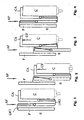
- Figs. 1-4 The general principle and function of the breath operated device according to the first aspect of the invention is shown schematically in Figs. 1-4.
- one part F is fixed in relation to the inhaler. In fact it could for example be the inhaler housing or the like.
- a second part, hereafter named shuttle S is movable in relation to the fixed part F.
- an actuating or firing force AF from for example a spring, is acting on the shuttle S.
- a third part, hereafter named canister actuator, CA is also movable in relation to the fixed part F and releasably attached to the shuttle S by a second movable locking means LM2.
- the canister actuator is arranged so that it is connected to the bottom of a canister C, which canister C in an inhaler is arranged so that its bottom is facing upwards and that its other end is provided with a valve assembly, which assembly is known per se.
- the canister C is pushed upwards in the figures by a spring of the canister valve assembly, causing a canister force CF.
- the first locking means LM1 When the inhaler is activated, in which a patient inhales, the first locking means LM1 is moved out of engagement with the fixed part F whereby the actuating force AF forces the shuttle S downwards, Fig. 2. Because the canister actuator CA is locked to the shuttle S by the second locking means LM2 it is also pushed downwards against the force CF of the canister valve assembly, thereby depressing the canister so that a metered dose of medicament is delivered.
- the second locking means LM2 is activated and releases the canister actuator CA, whereby the canister returns to its undepressed state and subsequently moves the canister actuator upwards.
- the shuttle S When the inhaler is to be charged and ready for use, the shuttle S is moved upwards, for example by the patient, whereby the two locking means LM1, LM2 engage and hold the device in its ready-to-use state.
- the locking means may be arranged in different ways in order to obtain the desired function between the parts.
- Figs. 5-7 show different arrangements.
- the locking means could be arranged as pulling or pushing elements in order to achieve the desired function.
- the different elements could for example be designed as shuttles, tubular elements arranged inside each other and the like.
- the inhaler since the inhaler is breath-operated, there are requirements that the forces needed to release the locking means are quite low in order to ensure that even patients with weak respiratory capacities are capable of activating the inhaler and receiving a dose of medicament.
- the device is arranged with force transmission means which enable a relatively low force to release the locking means, which in turn hold a rather strong actuating means. Examples of such force transmission means are described below.
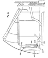
- FIG. 8-13 An example of an inhaling device according to a preferred embodiment of the present invention is shown in the figures 8-13.
- the inhaling device 10 is arranged in an inhaler, comprising a housing, in the embodiment shown in two detachable parts, where the upper part is shown in Figs. 8-9.
- the upper part is arranged with a holder/ chamber for a metered dose aerosol container, hereafter named canister.
- the canister contains the medicament. It is further provided with a valve assembly in the canister comprising a valve stem, which normally is urged downwardly by a compressed spring.
- the valve assembly further includes a small compartment or chamber in the canister, which chamber defines the metered dose to be inhaled.
- the valve stem is provided with in- and outlets for filling the metered dose chamber with medicament and delivering the metered dose depending on the position of the stem in the valve assembly, as will be described in detail below.
- valve stem The lower end of the valve stem is attached to, and supported by, a nozzle, which in turn is in communication with a mouthpiece.
- An air flow passage is arranged from an opening on the top of the housing to the mouthpiece arranged on the housing near the nozzle.
- an actuating means hereafter named pressure plate 34
- the pressure plate is arranged to a cylindrical body 36 movably arranged in the vertical direction around a support shaft 37.
- the lower part of the cylindrical body is arranged with an inwardly projecting ledge 38.
- a compression spring (not shown) is arranged around the support shaft between the ledge and a fixed upper abutment 40.
- the inhaler further comprises an actuator mechanism assembly. It comprises a flap 42 or vane, Fig. 9, pivotably arranged in a passage 43 in the inhaler.
- a first arm 44 pivotably is arranged with its upper end to a cylindrical shuttle 46.
- the arm 44 rests with its lower end on the flap or vane adjacent its pivoting point 47, Fig. 9.
- the shuttle is movably arranged around the cylindrical body, whereby the upper part of the shuttle is engaging a projection 48 on the outer surface of the cylindrical body.
- On the first shuttle two rotatable holding means 50 are arranged, Fig. 13. Between these a first fork-like member 52 is arranged.
- the fork-like member 52 is arranged with recesses 53 for receiving the holding means, as will be explained below.
- a pin 54 protruding from the cylindrical body, Fig. 11, is held between the forks of the fork-like member.
- the shuttle is further provided with a second arm 56, arranged parallel to the first arm. The second arm is shorter than the first arm, the reason of which will be explained below.
- a second set of rotatable holding members 58 are arranged, Fig. 12. Between these a fork-like member 60 is arranged, which is attached to the cylindrical body. The fork-like member has projections 62 on which the holding means rest and thereby holds the fork-like member in position. Between the forks of the fork-like member a protrusion 64 is arranged, which is attached to the pressure plate 34. Some distance downwards on the fork-like member, recesses 66 are cut out.
- the function of the device is as follows.
- the metered dose chamber is filled with medicament in a known fashion.
- the shuttle has been pushed upwards by a return means so that the first arm 44 rests on the flap or vane 42.
- the return means comprises an arm 70 extending downwards, and connected to for example a protective cover for a mouthpiece.
- the upper part of the return means is designed as a ring 72 surrounding the cylindrical body 36. Between the ring and the shuttle a spring is arranged (not shown).
- the return means is activated when the cover is closed after use, thus activating the inhaler before the subsequent use.
- the flap 42 When a user begins to inhale through the mouthpiece, the flap 42, arranged in the air conduit adjacent the air intake, is pivoted inwards by the pressure difference created on both sides of the flap. Due to the pivoting movement, the first arm 44 is pushed off the resting position on the flap or vane. This causes the shuttle 46 to move downwards, whereby the rotatable holding means 50 also are moved downwards until they reach the recesses 53. This enables the forks of the fork-like member 52 to move away from each other thereby releasing the pin 54 and thus the cylindrical body. The compression spring acting on the ledge 38 on the inner surface of the cylindrical body moves it and the pressure plate 34 downwards, thereby depressing the canister.
- the stem of the canister is attached to the stationary nozzle, the stem is pushed into the metered dose chamber of the canister, thereby opening the connection between the dose chamber and the nozzle.
- the metered dose is delivered through the nozzle and is mixed with the suction air and enters the respiratory tract of the patient.
- the downward movement of the shuttle causes the second arm 56 to engage with the flap or vane and rest there.
- the flap or vane is pivoted back to its original position.
- the pivoting movement causes the second arm to leave the rest position on the flap or vane, whereby the shuttle is moved downwards further.
- the second set of rotatable holding means 58 are also moved downwards, thereby permitting the forks of the second fork-like member 60 to move away from each other and release the pin 64 of the pressure plate, thus also releasing the pressure plate 34, so that the canister is returned to its undepressed by the spring of the valve assembly and the communication between the metered dose chamber and the nozzle is closed.
- the inhaler comprising a body, an aerosol canister arranged in said body containing medicament, comprising a metered dose chamber and able to dispense a metered dose of said medicament, a nozzle in fluid communication with said canister, an opening for dispensing of said medicament in fluid communication with said nozzle, said device comprising means (34, 36, 42, 44, 46, 50, 52) for activating said canister to open and dispense said medicament in response to an airflow in the inhaler caused by inhalation of a user through said opening, return means (42 46, 56, 58, 60) for deactivating said canister to close it, characterized in that said return means deactivates said canister when the airflow drops below a certain threshold value.
- the metered dose chamber is refilled and ready for the next dose. It is to be noted that the refilling of he metered dose chamber always is done when the inhaler and canister are held vertically, thus ensuring refilling of the metered dose chamber with medicament, even when small amounts of medicament remain in the canister.
- the inhaler could also be provided with detection and monitoring means providing information regarding the inhalation. These normally comprise counters for displaying the number of doses delivered or the number of doses that remain. With the device according to the invention, detection means for detecting the inhalation period may also be included because both the beginning and end of inhalation activates the device. The inhalation period is then an indication of the inhalation quality in the sense that if the device registers that a rather short inhalation has been done, this is an indication that the patient has not inhaled the medicament into the respiratory tract properly. The inhaler could then indicate to the user, to make him aware of this, and to suggest another dose.
- the measuring points for the detection means could be any of the moving part of the device of the invention, such as the flap, the shuttles, the pressure means, and so forth.
- the different springs acting in the device may have different configuration and/or attachment points in order to obtain the same function.
- the pressure means may be a vacuum bellows, known per se.
- return means than a protective cover, like for example a button, a sleeve, lever or the like of any kind and placement.
- a protective cover like for example a button, a sleeve, lever or the like of any kind and placement.
- the upper part of the housing may be slidable in respect to the lower part in a vertical direction for activating the return means in the described way.
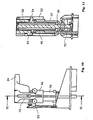
- Figure 14 shows an example of an inhaler.
- the inhaler 210 shown is intended for aerosol-driven medicament contained in a canister 212 arranged inside the housing 214 of the inhaler.
- a stem 216 of the canister is seated in a nozzle 218 provided with an outlet directed towards an inhalation mouthpiece 220.
- the inhaler is further provided with breath- activating means, which comprises a flap or vane 222 pivotably arranged adjacent an air intake 224 and substantially covering the intake when non-activated.
- the flap or vane is arranged with a protrusion 226 adjacent its pivoting point 228.
- a release means is arranged to the activating means, comprising an arm 230 which is arranged with a hook 232 at its upper end, which hook grips a ledge 234, in turn arranged close to the protrusion.
- a compression spring 236 is arranged between the arm and the, housing of the inhaler. The arm extends downward into a transmission and locking means 248.
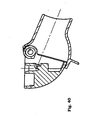
- a pressure arm 244 is arranged in contact with the top of the canister as seen in the figure and pivotable around a pivoting point 246 fixed to the housing.
- the transmission and locking means 248, Figs. 15 and 16 comprises a first pivoting locking member 250, pivotable around an axis 252, which axis is fixedly attached to a stationary plate 253, partly taken away in Fig. 15 for clarity.
- the locking means is arranged with a surface 254 inclined with respect to a vertical axis as seen in Fig. 15.
- the lower end of the arm 230 is arranged with a mating inclined surface 256.
- the locking member is provided with an upwards facing ledge 258, on which ledge a first transmission member 260, pivotable around an axis 261, rests with a recess 262, thus holding the first transmission member in a substantially horizontal position.
- the axis 261 is also fixedly attached to the plate 253.
- a second transmission member 264, arranged pivotably around an axis 266 in a vertical direction rests with a lower end on the second transmission member.
- the second transmission member is arranged with an arm 267 whose outer end is bent inwards.
- the upward facing surface 269 of the arm mates with a ledge arranged in a groove 271 of a movable plate 268.
- the shaft 266 of the second transmission member is also attached to the plate 253.
- a shuttle 276 is attached to the movable plate 268 via attachments 275.
- the lower end of the movable plate 268 is arranged with a ledge 270.
- An arm is attached to the shuttle 276. At the upper end of the arm a hook is arranged. The hook grips the free end of the pressure arm 244.
- the transmission and locking means also comprises suitable guide means for the different components, not shown.
- the function is as follows. When a patient inhales through the mouthpiece 220, a pressure difference is created between the interior of the inhaler and the outside, and thus a pressure difference over the flap or vane 222. The pressure difference causes the flap or vane to pivot around its pivoting point 228. The pivoting movement causes the protrusion 226 to push the hook 232 of the arm 230 off the ledge 234 whereby it is forced downwards by the compression spring 236.
- the gap between the arm 230 and the locking member 250 provides an acceleration of the arm and thus a certain dynamical force. This force provides an additional feature and advantage in designing the system and the requirements for releasing the locking member.
- the movement and the inclined surfaces causes the locking member to pivot clockwise in Fig. 15 whereby the ledge 258 of the locking member is pushed out of contact with the recess 262 of the first transmission member 260.
- the first transmission member is thereby free to turn downwards, whereby the arm 267 of the second transmission member 264 is moved out of contact with the recess of the groove 271.
- the force of the compression springs is transmitted to the canister 212 via the pressure arm 244 and the canister is depressed.
- connection between the activating means and the actuating means is not dependent on an actual gap between the parts, as shown in the Figures.
- the parts may well be contacting each other.
- the main importance is that the operation of the activating means is influenced as little as possible by the actuating means and that it is ensured that the activating means always is capable of activating the actuating means upon inhalation.
- This approach enables to design the system so that care is taken of the differences in the properties of all components of the transmission and actuating means in order to have a reliable, predictable and repeatable activation of the inhaler.
- the transmission may also be of any mechanism capable of transferring a movement and capable of enabling a low force to release a high force.
- dependent means that one component is moved to an end position and thereby triggers a subsequent component.
- independent means that one component is moved to an end position. The subsequent triggering is then performed by external activation.
- a return means could also be provided with the same function as the above described device.
- This could comprise a second locking and transmission means replacing the attachments 275 between the movable plate and the shuttle 276. It comprises a further arm, which, upon termination of inhalation, is released by the flap or vane, whereby it moves the second locking means out of locking position.
- This causes the shuttle 276 to be released from the movable plate 268, whereby the canister is returned to its non-depressed state by the spring arranged in the canister.
- Return means arranged to the movable plate 268 will push it upwards to the initial position, which for example may be done manually by shutting a hygiene lid or pushing a button.
- injectors of the above described type several devices may also be used in one injector. For instance one may be associated with the triggering of needle penetration, which is often done by pushing the syringe forward in the housing of the injector. When the syringe is in the forward position, this triggers the emptying of the syringe. This is done by springs pushing the plunger into the syringe. When the plunger has reached the dose end position or bottom and the dose is delivered, this triggers a needle retraction or a needle protection to be pushed forward. There could thus be a series of components or transmissions acting in sequence, where each sequence could make use of the "broken connection". There is thus easier to take into account and deal with variations in the characteristics of the components in the chain when calculating the forces required for the reliable function of the device.
- FIG 17 shows an example of an inhaler.
- the inhaler 300 shown is intended for aersol-driven medicament contained in a canister 302 arranged inside the housing 304 of the inhaler.
- a stem 306 of the canister is seated in a nozzle 308 provided with an outlet directed toward an inhalation mouthpiece 310.
- Pressure means 312 is arranged in contact with the top of the canister as seen in the figure.
- the pressure means comprises a piston 314 and a pressure plate 316.
- Compression springs 318 are arranged between the pressure plate and the housing.
- Actuating means 320 are arranged in connection with the pressure plate for holding it in a position where the compression springs are tensioned.
- the actuating means further comprise levers and shuttles.
- Fig. 18 shows a detail of a component 322 of a breath- activated inhaler.
- the component comprises an air intake passage 324 , through which air flows during inhalation.
- a flap or vane 326 is arranged pivotably around a pivot axis 328.
- Spring means urges the pivot upwards in Fig. 18 against the interior wall of the air intake. In this position the flap or vane substantially blocks the air intake passage.
- the part of the vane opposite the pivoting axis is connected to the actuating means 320.
- the general function of the component is that during inhalation, a pressure difference is created between the interior and the exterior of the inhaler housing 304.
- This pressure difference causes the flap or vane 326 to pivot around the pivoting axis 328 against its spring means so that the air intake opens and an air flow is created.
- the pivoting movement of the flap or vane triggers the actuating means so that the hold of the pressure plate 316 is released whereby the springs 318 depresses the canister 302.
- the stem 306 is pushed into the canister whereby a dose of medicament is delivered through the mouthpiece 310.
- the flap or vane is arranged with balancing means 332.
- balancing means 332 In the embodiment shown in Figs. 18 and 19 it comprises a weight arranged on the opposite side of the pivoting point in relation to the flap or vane.
- the centre of mass 334 of the weight is arranged in the same plane as the centre of mass 336 of the flap or vane and the pivoting point.
- the weight of the balancing means is chosen such that the weight times the distance to the pivoting point equals the weight of the flap or vane times the distance between its centre of weight and the pivoting point.
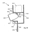
- Figs. 20-22 show an embodiment where the flap or vane 326 is not balanced in all directions.
- the weight 332 is placed somewhat below the pivoting point and the flap or vane.
- the centres of mass 336 of the flap or vane and the balancing means 334 and the pivoting point 16 will not be arranged in the same plane.
- the flap or vane will be substantially balanced along the line 338 intersecting the pivoting point and the resulting centre of mass.
- This configuration may be due to the limited space available in the inhaler.
- the resulting centre of mass 336 will thus not coincide with the pivoting point of the flap or vane but with the line 338. It is however arranged such that the flap or vane is balanced for forces exerted on the inhaler in selected directions. For example with an aerosol inhaler it is recommended that it is shaken before use so that the medicament inside the canister is properly suspended. Depending on design of the inhaler, i. e. how it is held, it is shaken in certain directions. The inhaler shown in Fig. 17 will be shaken substantially in the vertical direction as shown by arrows 330. The flap or vane is then substantially balanced with respect to those directions.
- Fig. 23 shows another inhaler.
- the inhalation forces are kept low, making it necessary to have the actuating means respond to these low forces.
- the depression forces need to be rather high in order to be capable of overcoming the forces for depressing the canister. Therefore, it is necessary with some kind of transmission mechanism which amplifies the movement from the flap or vane to the compression springs.
- Fig. 23 shows one example of how the first link of the transmission comprises a lever 350 pivotably arranged.
- the lever is connected to the flap or vane 326 via a piston 352.
- a second arm 354 or lever is connected to the lever via a ledge 356.
- the transmission 358 comprises further arms, levers, pistons, shuttles and the like in order to transmit and transfer the movement to a holding means 360 holding the pressure plate 316 against the force of the compression springs 318.
- the flap 326 is pivoted around its pivoting axis whereby the piston 352 is pushed downwards.
- the piston pivots the lever 350 whereby the arm 354 disconnects from the ledge.
- the movement is transferred through the transmission until the holding means 360 releases the pressure plate. Because very small forces are needed, and desired, in order to pivot the lever, it is balanced against external forces.
- a weight 362 is arranged on the opposite side of the pivoting point and chosen such that the resulting centre of mass of the weight an the lever coincides with the pivoting point 364, whereby the lever is balanced against directed forces, for example vertically as seen in Fig. 23.
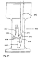
- Fig. 24 shows a detailed view of a locking and release means 366 for a breath activated inhaler. It comprises a first pivoting member 368 pivotable around an axis. The first member is arranged with a surface 370 inclined with respect to a vertical axis. The lower end of an arm 372 arranged to a breath activated member, not shown, is arranged with a mating inclined surface 374. The first member is provided with an upwards facing ledge 376, on which ledge a second pivotable member 378 rests with a recess 380, thus holding the second member in a substantially horizontal position. A third member 382, arranged slidably in a vertical direction rests with a lower end on the second member.
- the third member is attached to a holding member, which holds for example pressure springs arranged to a canister of an inhaler in an energised, tensioned state.
- a holding member which holds for example pressure springs arranged to a canister of an inhaler in an energised, tensioned state.
- this embodiment may be used for balancing statical as well as dynamical forces, i e predetermined directions of movement, non-predetermined directions of movement as well as movements in several planes.
- pivotably may be members balancing on an edge, or that the shaft on which a pivoting member is arranged is smaller than the hole, so that there is one specific contact point, pivoting point, between the shaft and the hole.
- the canister is arranged with a stem containing a passage at its lower part.
- the stem protrudes inside the canister, and when the canister is depressed a dose of medicament is delivered through the passage of the stem.
- the stem communicates with an inhalation opening, through which the dose is delivered.
- a depressing means is arranged at the upper part of the canister.
- it comprises a pivotally arranged lever 412 with a portion that is curved downwards somewhat corresponding to the concave shape of the canister end wall.
- a depression means is arranged, comprising a compression spring (not shown) attached via an arm 416 to the end of the lever.
- an activating means is arranged comprising a flap 426 pivotally arranged in the inhaler in an air passage 428 communicating with the exterior of the inhaler.
- the shape of the flap and the passage is such that the flap substantially closes the passage when it is in its uppermost position, Fig. 25.
- the flap is connected to the depression means.
- the inhalation causes a pressure difference between the interior of the inhaler and the exterior.
- This pressure difference causes the flap 246 to pivot and the passage 428 to open so that an air flow is created.
- the pivoting movement of the flap acts on the depression means so that the compression spring pulls the arm 416 downwards whereby the lever 412 is pivoted downwards.
- the pivoting force depresses the canister 410 so that a dose of medicament is delivered.
- An adjustment means 440 is also arranged in the inhaler. It comprises a generally L-shaped member 442 arranged in a compartment 444 and movable in a vertical direction. The lower branch of the L-shaped member protrudes somewhat over the end wall of the canister. The lever 412 is pivotally arranged to the lower branch of the L-shaped member adjacent the intersection point with the upper branch.
- a vertically acting compression spring 446 is arranged between the inhaler housing and the lower branch of the L-shaped member, where the contact point 448 of the spring is somewhat closer to the canister than the pivoting point 414 of the lever.
- the upper branch of the L-shaped member is provided with a number of teeth 450 arranged on the surface facing inwards.
- the opposite surface of the compartment is provided with a number of corresponding teeth 452.
- the adjusting member is shown with an L-shape where the branch with teeth is facing upwards, this member could be facing downwards with the teeth on the other side of the branch and corresponding teeth on an opposite surface. Further, other configurations of the member are conceivable for obtaining the same function of the height adjustment. Also fixating means other than teeth could be used.
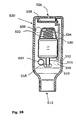
- Fig. 28 shows, as an example, an inhaler for aerosol-driven medicament.
- the inhaler comprises a housing 510 with an opening 512 intended for inhalation of a dose of medicament.
- a canister 514 containing the medicament and aerosol as propellant.
- the canister is provided with dose delivery mechanism comprising a spring-loaded stem 516.
- the stem is provided with a passage extending into the canister.
- the stem/lower part of the canister is supported by a holding/fixating device 518.
- an activating means 520 is arranged at the opposite end of the canister stem. It comprises in the embodiment shown a spring 522 with one end pressing on the canister and the other end supported by a holder 524.
- the activating means further comprises an air inlet 526 arranged in the inhaler housing and a flap 528 pivotally arranged adjacent the air intake.
- a holding means 530 which in the embodiment shown comprises an elongated arm extending alongside the canister side.
- the arm is at its lower end arranged with a ledge 532.
- the arm and the ledge holds the canister in an inactivated position against the force of the spring.
- the interior of the inhaler, from the inhalation opening to the air intake forms an air passage.
- the inhaler further comprises a safety means. It comprises at least one auxiliary air intake 534 arranged to communicate with the inhaler air passage, forming an auxiliary air passage with the inhalation opening, where the intake is positioned between the inhalation opening and the flap/ main air intake. Further auxiliary air intakes 536 are shown with broken lines.
- the start of an inhalation through the inhalation opening causes a pressure difference between the interior and the exterior of the inhaler.
- This pressure difference causes the flap to pivot, thereby causing an air flow through the inhaler from the air intake to the inhalation opening.
- the pivoting movement of the flap acts on the elongated arm so that the arm is swung away somewhat from the canister. This causes the ledge to release the canister from its inactivated position.
- the force of the spring causes the canister to depress whereby the stem is pressed into the canister and a dose is delivered to the inhalation opening, which dose is inhaled by the patient.
- Fig. 29 shows another example of an inhaler.
- the inhaler shown is intended for medicament in powder form.
- the inhaler comprises a housing 540. At one end of the housing a mouthpiece 542 with an inhalation opening 544 is arranged.
- the mouthpiece can be protected by a protective cover 546.
- the means comprises an elongated body 548 with a passage through its length, hereafter named outlet passage.
- One end 550, the one facing inwards, is arranged with sharpened edges.
- the elongated body is slidably supported in a hole in the opening, whereby the other end of the elongated body is arranged in the opening.
- An activating means is arranged to the elongated body, comprising an air intake 552, a flap 554 pivotally arranged adjacent the air intake and a mechanism 556 designed to be able of moving the elongated body inwards when the flap is opened.
- a wheel 558 is rotatably arranged.
- the wheel is arranged with a plurality of recesses 560 and means for rotating the wheel to different positions.
- the medicament is packaged in blisters, where each blister enclosure contains one dose of medicament.
- the blister enclosures are placed in the recesses.
- the inhaler further comprises a safety means. It comprises at least one auxiliary air intake 580 arranged to communicate with the inhaler interior, forming an auxiliary air passage with the inhalation opening.
- the inhalation causes a pressure difference between the interior and the exterior of the inhaler.
- This pressure difference causes the flap 554 to open and an air flow to be created through the air intake 552 and the passage of the elongated body 548.
- the movement of the flap causes the activating means to move the elongated body forward so that its pointed end penetrates the blister enclosure whereby a passage between the interior of the enclosure and the inhalation opening is created so that medicament is inhaled.
- auxiliary air intake may be closed or blocked by the fingers of the patient or by a mechanical means. Since the greatest risk of unintentional inhalation is from children, the air intakes should preferably be placed so that a child cannot close the auxiliary intake without great effort.
- auxiliary air intake is such that a child's finger cannot block it.
- auxiliary air intakes arranged in the inhaler housing so that it is difficult for a child to place several fingers over all of the intakes. Further the distance between the intakes could be such that it is impossible for a child's hand to reach all the intakes.
- the device could be designed such, and with the auxiliary air intakes positioned such that both hands are needed in order to cover or block all intakes.
- the activating means is arranged such that it is only activated when a pressure drop corresponding to a complete blocking of all intakes is reached, i e it shall not be sufficient to block some of the auxiliary air intakes in order to activate the inhaler.
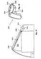
- An inhaler 610 comprising a device 611 consists of a body 612, where only the lower part is shown in the drawings, a compartment 614 containing medicament, an air passage 616 and an opening 617.
- the compartment is in a known way connected to the air passage 616 for dispensing of a metered dose of medicament to the patient during inhalation.
- the device comprises a mouthpiece 618 with a back and a front end 620, 622 in fluid communication with the air passage.
- the back end 620 is pivotably arranged to an axis 624 inside the body so that the mouthpiece may be pivoted between a rest/protected position, Fig. 35, to an activated, ready-to-use position, Fig. 30 and 32.
- a torsion spring 626 is arranged between the mouthpiece and the body for urging the mouthpiece towards the activated position and for holding it in that position.
- a protective cover or lid 628 is pivotably arranged to an axis 630.
- the inside of the cover is arranged with a protruding surface 632.
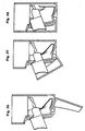
- Figs. 31 and 36-38 show another embodiment, where the same components have the same reference numerals.
- the mouthpiece is arranged slidable in the body.
- the mouthpiece is arranged with protrusions 634 attached to opposite side of the mouthpiece.
- the protrusions are slidably arranged in grooves 636 in the body.
- the inner end of the mouthpiece is arranged with a downward extending arm 638.
- a pusher spring 640 is arranged between the mouthpiece and the body.
- An enclosing wall 642 is arranged around the mouthpiece. With this design the whole interior of the body may act as an air passage for the inhaling air, and thus no specific air passage is to be arranged and connected to the mouthpiece.
- the wall also serves as a guide and support for the mouthpiece.
- the mouthpiece When the inhaler is activated, the mouthpiece protrudes through the opening by the spring and held in this position, while the protrusions abut the outer ends of the grooves.
- the patient When the patient has inhaled the dose of medicament, he closes the cover by pivoting it. The inner surface of the cover then pushes the mouthpiece whereby it slides in its longitudinal direction 642 by the protrusions and the groove.
- Fig. 39 shows an example of an inhaler for aerosol driven medicaments with a pivoting mouthpiece.
- the pivoting point 650 is placed such that the nozzle 652 in fluid communication with the canister 654 is in line with the mouthpiece 618 when it is in the inhaling position.
- a general desire in this respect is that the pivoting point is placed as close to the canister/nozzle as possible to minimise the height of the inhaler, and as far to the protruding side of the inhaler/mouthpiece as possible so that the mouthpiece protrudes such an extent that it is easily placed in the mouth.
- the pivoting mouthpiece is also provided with a covering wall 656, which, when the mouthpiece is in the inhaling position, covers the interior of the inhaler, which may comprise other mechanisms for handling the inhaler.
- the protective cover/lid may also be arranged with holding means, not shown, for preventing the mouthpiece to pivot back when in the inhaling position.
- Figure 40 shows a mouthpiece wherein the movable mouthpiece and the spray head with nozzle is made as one replaceable unit. This arrangement is convenient when the inhaler as such is intended for long time use. The mouthpiece and the spray head often become clogged or smeared with medicament after some use. Therefore, it is practical that they may be removed as a unit for replacement or cleaning.
- the protective cover/lid may be opened by pressing or sliding a button, lever or the like, and placed on the inhaler in such a way as to coincide with the ergonomical conditions of the user.
- it may comprise two buttons or activating points that have to pressed or activated at the same time.
- the protective cover is a sleeve, for example slidable in the longitudinal direction of the inhaler.
- the sleeve may also be so long that it constitutes the major outer surface of the inhaler, and that the user holds the sleeve when holding the inhaler.
- the upper part of the sleeve is open, through which the inhaler body protrudes.
- the body By pressing the upper end of the body downwards, it slides inside the sleeve, whereby the lower part of the body, comprising the movable mouthpiece, is arranged below the sleeve, thus exposing the mouthpiece, and the inhaler is ready to use.
- the device can further be provided with means for reactivating, returning and recharging means of the inhaler after delivery of a dose.
- These means may include placing the inhaler in a ready-to-use state, wherein the metered dose compartment is refilled/recharged, that the means for delivering a dose, like pressure springs acting on an aerosol canister, are re-tensioned, and the like.
- these means are activated by the protective cover/lid when it is closed. Tensioning of springs and the like is facilitated in that the protective cover/lid may be used as a lever, thereby reducing the force needed.
- the mouthpiece may be pivotable around a vertically arranged axis instead of a horizontal axis, which axis may coincide with the outlet of the metered dose compartment.
- This design has the advantage of requiring less space in that the mouthpiece is swung sideways in and out from the inhaler body, thus reducing the height of the inhaler.
- the mouthpiece may be formed by several telescopically acting parts in order to obtain the protruding effect.
- the moving action of the mouthpiece from an activated position to a protected rest position may also be obtained by other means, such as cam-shaped ribs or protrusions or some form of linkage between the cover and the mouthpiece.
Abstract
Description
The shuttle is further provided with a
Claims (9)
- Device for use with an inhaler, the inhaler comprising a body, an aerosol canister arranged in said body containing medicament, said canister comprising a metered dose chamber and being able to dispense a metered dose of said medicament, the inhaler further comprising a nozzle in fluid communication with said canister, and an opening for dispensing of said medicament in fluid communication with said nozzle, said device comprising means (34, 36, 42, 44, 46, 50, 52) for activating said canister to open and dispense said medicament in response to an airflow in the inhaler caused by inhalation of a user through said opening, return means (42, 46, 56, 58, 60) for deactivating said canister to close it,
characterized in that said return means is configured to deactivate said canister when the airflow drops below a certain threshold value. - Device according to claim 1, characterized in that said return means is configured to deactivate said canister in response to ending and/or termination of inhalation.
- Device according to claim 1 or 2, characterized in that said activating means comprises first spring means, hereafter named pressure spring means, for moving the canister relative the housing to vent the metered dose chamber and that said return means comprises second spring means, hereafter named return spring means, for moving the canister relative the housing to an unvented position against the force of the first spring means.
- Device according to any of the preceding claims, characterized in that the activating means and return means of the device are operated, during use, when the canister is positioned with its outlet facing downwards in the inhaler.
- Device according to claim 4, characterized in that the metered dose chamber is refilled/recharged, in use, during deactivation of the canister.
- Device according to claim 3, characterized in that said return spring means of the return means is activated, in use, by the user.
- Device according to claim 3, characterized in that said activating means comprises a pressure means (34, 36, 38) in contact, in use, with the bottom of the canister, that the pressure spring means are arranged between the pressure means and the housing of the inhaler, holding means (46, 52) for holding said pressure means, thereby preventing said pressure spring means and pressure means to depress the canister, support means (50) for supporting said holding means in holding said pressure means, and release/return mechanism (46, 58, 60) which is activatable in response to an airflow due to inhalation, whereby, upon activation, the support means releases said holding means which in turn releases said pressure means and the canister is depressed.
- Device according to claim 7, characterized in that the return spring means of the return means is arranged to said support means, whereby upon termination of inhalation, said release/return mechanism activates said second spring means to urge said support means in supporting contact with said spacer means, whereby said spacer means urges the pressure means to a position where the canister is no longer depressed.
- Device according to any of the preceding claims, characterized in that it comprises detecting/monitoring means for detecting/monitoring the time between activation and deactivation of the canister.
Priority Applications (1)
| Application Number | Priority Date | Filing Date | Title |
|---|---|---|---|
| EP05102951A EP1568390A3 (en) | 1999-06-18 | 2000-06-16 | Inhaler |
Applications Claiming Priority (13)
| Application Number | Priority Date | Filing Date | Title |
|---|---|---|---|
| SE9902349A SE516826C2 (en) | 1999-06-18 | 1999-06-18 | Breath-operated device for use with an inhaler includes a return mechanism for deactivating a canister to close when airflow drops below a certain threshold value |
| SE9902349 | 1999-06-18 | ||
| SE9902365A SE517979C2 (en) | 1999-06-21 | 1999-06-21 | Breath-operated device for use with an inhaler includes a return mechanism for deactivating a canister to close when airflow drops below a certain threshold value |
| SE9902365 | 1999-06-21 | ||
| SE9903678 | 1999-10-12 | ||
| SE9903663 | 1999-10-12 | ||
| SE9903678A SE521287C2 (en) | 1999-10-12 | 1999-10-12 | Breath-operated device for use with an inhaler includes a return mechanism for deactivating a canister to close when airflow drops below a certain threshold value |
| SE9903663A SE519022C2 (en) | 1999-10-12 | 1999-10-12 | Breath-operated device for use with an inhaler includes a return mechanism for deactivating a canister to close when airflow drops below a certain threshold value |
| SE0000733 | 2000-03-06 | ||
| SE0000732A SE518506C2 (en) | 2000-03-06 | 2000-03-06 | Breath-operated device for use with an inhaler includes a return mechanism for deactivating a canister to close when airflow drops below a certain threshold value |
| SE0000733A SE518511C2 (en) | 2000-03-06 | 2000-03-06 | Breath-operated device for use with an inhaler includes a return mechanism for deactivating a canister to close when airflow drops below a certain threshold value |
| SE0000732 | 2000-03-06 | ||
| PCT/SE2000/001278 WO2000078378A1 (en) | 1999-06-18 | 2000-06-16 | Inhaler |
Related Child Applications (1)
| Application Number | Title | Priority Date | Filing Date |
|---|---|---|---|
| EP05102951A Division EP1568390A3 (en) | 1999-06-18 | 2000-06-16 | Inhaler |
Publications (2)
| Publication Number | Publication Date |
|---|---|
| EP1204438A1 EP1204438A1 (en) | 2002-05-15 |
| EP1204438B1 true EP1204438B1 (en) | 2005-06-08 |
Family
ID=27555293
Family Applications (2)
| Application Number | Title | Priority Date | Filing Date |
|---|---|---|---|
| EP05102951A Withdrawn EP1568390A3 (en) | 1999-06-18 | 2000-06-16 | Inhaler |
| EP00944542A Expired - Lifetime EP1204438B1 (en) | 1999-06-18 | 2000-06-16 | Inhaler |
Family Applications Before (1)
| Application Number | Title | Priority Date | Filing Date |
|---|---|---|---|
| EP05102951A Withdrawn EP1568390A3 (en) | 1999-06-18 | 2000-06-16 | Inhaler |
Country Status (11)
| Country | Link |
|---|---|
| US (2) | US6866037B1 (en) |
| EP (2) | EP1568390A3 (en) |
| AT (1) | ATE297234T1 (en) |
| AU (1) | AU767467B2 (en) |
| CA (1) | CA2377533C (en) |
| DE (1) | DE60020715T2 (en) |
| DK (1) | DK1204438T3 (en) |
| ES (1) | ES2243277T3 (en) |
| PT (1) | PT1204438E (en) |
| SE (1) | SE516826C2 (en) |
| WO (1) | WO2000078378A1 (en) |
Families Citing this family (61)
| Publication number | Priority date | Publication date | Assignee | Title |
|---|---|---|---|---|
| US9006175B2 (en) | 1999-06-29 | 2015-04-14 | Mannkind Corporation | Potentiation of glucose elimination |
| FR2813214B1 (en) * | 2000-08-29 | 2003-05-02 | Valois Sa | IMPROVED FLUID PRODUCT DISPENSING DEVICE |
| US7931022B2 (en) * | 2001-10-19 | 2011-04-26 | Respirks, Inc. | Method and apparatus for dispensing inhalator medicament |
| FR2834277B1 (en) * | 2001-12-28 | 2004-06-11 | Valois Sa | FLUID PRODUCT DISPENSING DEVICE |
| JP4681231B2 (en) | 2002-03-20 | 2011-05-11 | マンカインド コーポレイション | Inhaler |
| GB2401321B (en) * | 2002-03-22 | 2005-12-07 | Clinical Designs Ltd | Can fixture |
| GB0304000D0 (en) * | 2003-02-21 | 2003-03-26 | Clinical Designs Ltd | Dispenser |
| GB0327112D0 (en) * | 2003-11-21 | 2003-12-24 | Clincial Designs Ltd | Dispenser and reservoir |
| GB0328859D0 (en) * | 2003-12-12 | 2004-01-14 | Clinical Designs Ltd | Dispenser and counter |
| FR2873584B1 (en) * | 2004-08-02 | 2006-11-17 | Jean Jacques Hubinois | TOBACCO WEANING SYSTEM |
| BRPI0514263B8 (en) | 2004-08-20 | 2021-05-25 | Mannkind Corp | method for the synthesis of n-protected bis-3,6-[4-aminobutyl]-2,5-diketopiperazine n-protected |
| KR101306384B1 (en) | 2004-08-23 | 2013-09-09 | 맨카인드 코포레이션 | Diketopiperazine salts, diketomorpholine salts or diketodioxane salts for drug delivery |
| GB0425518D0 (en) | 2004-11-19 | 2004-12-22 | Clinical Designs Ltd | Substance source |
| GB0428204D0 (en) | 2004-12-23 | 2005-01-26 | Clinical Designs Ltd | Medicament container |
| CA2550667C (en) * | 2005-07-15 | 2013-06-25 | Shl Medical Ab | Injector |
| US7955304B2 (en) * | 2005-07-15 | 2011-06-07 | Shl Group Ab | Injector |
| DK1743666T3 (en) | 2005-07-15 | 2009-08-24 | Shl Group Ab | Injector with automatic needle insertion, injection and needle extraction |
| GB0518400D0 (en) | 2005-09-09 | 2005-10-19 | Clinical Designs Ltd | Dispenser |
| EP1928423B1 (en) | 2005-09-14 | 2015-12-09 | Mannkind Corporation | Method of drug formulation based on increasing the affinity of active agents for crystalline microparticle surfaces |
| WO2007098500A2 (en) | 2006-02-22 | 2007-08-30 | Mannkind Corporation | A method for improving the pharmaceutic properties of microparticles comprising diketopiperazine and an active agent |
| EP2035068A1 (en) * | 2006-06-27 | 2009-03-18 | Brin Tech International Limited | Inhaler |
| JP5241714B2 (en) * | 2006-07-07 | 2013-07-17 | プロテウス デジタル ヘルス, インコーポレイテッド | Smart parenteral delivery system |
| US20080178872A1 (en) * | 2006-12-01 | 2008-07-31 | Perry Genova | Dose selective breath actuated inhaler |
| EP2211974A4 (en) * | 2007-10-25 | 2013-02-27 | Proteus Digital Health Inc | Fluid transfer port information system |
| US8419638B2 (en) * | 2007-11-19 | 2013-04-16 | Proteus Digital Health, Inc. | Body-associated fluid transport structure evaluation devices |
| US8485180B2 (en) | 2008-06-13 | 2013-07-16 | Mannkind Corporation | Dry powder drug delivery system |
| CA2982550C (en) * | 2008-06-13 | 2020-08-25 | Mannkind Corporation | A dry powder inhaler and system for drug delivery |
| CN102065942B (en) | 2008-06-20 | 2013-12-11 | 曼金德公司 | An interactive apparatus and method for real-time profiling of inhalation efforts |
| TWI494123B (en) | 2008-08-11 | 2015-08-01 | Mannkind Corp | Use of ultrarapid acting insulin |
| CA2746859A1 (en) * | 2008-12-19 | 2010-06-24 | Novartis Ag | Mouthpiece for an inhaler |
| US8314106B2 (en) | 2008-12-29 | 2012-11-20 | Mannkind Corporation | Substituted diketopiperazine analogs for use as drug delivery agents |
| GB0904059D0 (en) | 2009-03-10 | 2009-04-22 | Euro Celtique Sa | Counter |
| GB0904040D0 (en) | 2009-03-10 | 2009-04-22 | Euro Celtique Sa | Counter |
| PL2405963T3 (en) | 2009-03-11 | 2014-04-30 | Mannkind Corp | Apparatus, system and method for measuring resistance of an inhaler |
| EP2239002B1 (en) * | 2009-03-30 | 2013-05-01 | Sanovel Ilaç Sanayi Ve Ticaret Anonim Sirketi | Dry powder inhaler device and lock mechanism |
| ES2943333T3 (en) | 2009-06-12 | 2023-06-12 | Mannkind Corp | Diketopiperazine microparticles with defined surface areas |
| EP2496295A1 (en) | 2009-11-03 | 2012-09-12 | MannKind Corporation | An apparatus and method for simulating inhalation efforts |
| US8332020B2 (en) | 2010-02-01 | 2012-12-11 | Proteus Digital Health, Inc. | Two-wrist data gathering system |
| AU2011210648B2 (en) | 2010-02-01 | 2014-10-16 | Otsuka Pharmaceutical Co., Ltd. | Data gathering system |
| AU2011271097B2 (en) | 2010-06-21 | 2014-11-27 | Mannkind Corporation | Dry powder drug delivery system and methods |
| CN103826988B (en) | 2011-04-01 | 2016-03-09 | 曼金德公司 | For the blister package of pharmaceutical kit |
| WO2012174472A1 (en) | 2011-06-17 | 2012-12-20 | Mannkind Corporation | High capacity diketopiperazine microparticles |
| JP6018640B2 (en) | 2011-10-24 | 2016-11-02 | マンカインド コーポレイション | Analgesic composition effective for alleviating pain, and dry powder and dry powder drug delivery system comprising the composition |
| GB201118845D0 (en) | 2011-11-01 | 2011-12-14 | Euro Celtique Sa | Dispenser |
| US9802012B2 (en) | 2012-07-12 | 2017-10-31 | Mannkind Corporation | Dry powder drug delivery system and methods |
| WO2014066856A1 (en) | 2012-10-26 | 2014-05-01 | Mannkind Corporation | Inhalable influenza vaccine compositions and methods |
| KR102391750B1 (en) | 2013-03-15 | 2022-04-28 | 맨카인드 코포레이션 | Microcrystalline diketopiperazine compositions and methods |
| CN105451716A (en) | 2013-07-18 | 2016-03-30 | 曼金德公司 | Heat-stable dry powder pharmaceutical compositions and methods |
| US11446127B2 (en) | 2013-08-05 | 2022-09-20 | Mannkind Corporation | Insufflation apparatus and methods |
| EP4295880A2 (en) | 2013-08-20 | 2023-12-27 | Boehringer Ingelheim Vetmedica GmbH | Inhaler |
| KR102502328B1 (en) | 2013-08-20 | 2023-02-23 | 베링거잉겔하임베트메디카게엠베하 | Inhaler |
| NZ714524A (en) * | 2013-08-20 | 2020-07-31 | Boehringer Ingelheim Vetmedica Gmbh | Inhaler |
| US10307464B2 (en) | 2014-03-28 | 2019-06-04 | Mannkind Corporation | Use of ultrarapid acting insulin |
| US10173025B2 (en) * | 2014-04-21 | 2019-01-08 | Idtx Systems, Inc. | Automated drug delivery systems |
| US10561806B2 (en) | 2014-10-02 | 2020-02-18 | Mannkind Corporation | Mouthpiece cover for an inhaler |
| US10561814B2 (en) | 2014-11-19 | 2020-02-18 | Idtx Systems, Inc. | Automated drug dispensing systems with automated HME bypass for ventilator circuits |
| TWI693079B (en) | 2015-01-08 | 2020-05-11 | 美商凸性科學有限責任公司 | Nebulizer device |
| ES2745552T3 (en) | 2015-07-20 | 2020-03-02 | Pearl Therapeutics Inc | Aerosol delivery systems |
| ES2882032T3 (en) | 2015-12-21 | 2021-12-01 | Kindeva Drug Delivery Lp | Flow regulator assemblies for use in medicinal inhalers |
| WO2017112748A1 (en) | 2015-12-21 | 2017-06-29 | 3M Innovative Properties Company | Flow govenors for use in medicinal inhalers |
| GB201615185D0 (en) | 2016-09-07 | 2016-10-19 | 3M Innovative Properties Co | Reset mechanism for an inhaler |
Family Cites Families (10)
| Publication number | Priority date | Publication date | Assignee | Title |
|---|---|---|---|---|
| US3151618A (en) * | 1960-12-22 | 1964-10-06 | Risdon Mfg Co | Dispensing device |
| US3456644A (en) * | 1967-01-19 | 1969-07-22 | Dart Ind Inc | Inhalation-actuated aerosol dispensing device |
| US5119806A (en) * | 1987-05-12 | 1992-06-09 | Glaxo Inc. | Inhalation device |
| EP0705614B1 (en) * | 1989-04-28 | 2002-09-25 | Riker Laboratories, Inc. | Dry powder inhalation device |
| GB8919131D0 (en) * | 1989-08-23 | 1989-10-04 | Riker Laboratories Inc | Inhaler |
| GB9015077D0 (en) * | 1990-07-09 | 1990-08-29 | Riker Laboratories Inc | Inhaler |
| US5027808A (en) * | 1990-10-31 | 1991-07-02 | Tenax Corporation | Breath-activated inhalation device |
| GB9026191D0 (en) * | 1990-12-01 | 1991-01-16 | Harris Pharma Ltd | Breath actuated dispensing device |
| US5364838A (en) * | 1993-01-29 | 1994-11-15 | Miris Medical Corporation | Method of administration of insulin |
| US5826571A (en) * | 1995-06-08 | 1998-10-27 | Innovative Devices, Llc | Device for use with metered dose inhalers (MDIS) |
-
1999
- 1999-06-18 SE SE9902349A patent/SE516826C2/en not_active IP Right Cessation
-
2000
- 2000-06-16 DE DE60020715T patent/DE60020715T2/en not_active Expired - Lifetime
- 2000-06-16 ES ES00944542T patent/ES2243277T3/en not_active Expired - Lifetime
- 2000-06-16 AT AT00944542T patent/ATE297234T1/en active
- 2000-06-16 PT PT00944542T patent/PT1204438E/en unknown
- 2000-06-16 WO PCT/SE2000/001278 patent/WO2000078378A1/en active IP Right Grant
- 2000-06-16 EP EP05102951A patent/EP1568390A3/en not_active Withdrawn
- 2000-06-16 AU AU58627/00A patent/AU767467B2/en not_active Ceased
- 2000-06-16 DK DK00944542T patent/DK1204438T3/en active
- 2000-06-16 EP EP00944542A patent/EP1204438B1/en not_active Expired - Lifetime
- 2000-06-16 US US10/018,242 patent/US6866037B1/en not_active Expired - Fee Related
- 2000-06-16 CA CA002377533A patent/CA2377533C/en not_active Expired - Fee Related
-
2004
- 2004-08-23 US US10/923,011 patent/US7347202B2/en not_active Expired - Fee Related
Also Published As
| Publication number | Publication date |
|---|---|
| WO2000078378A1 (en) | 2000-12-28 |
| DK1204438T3 (en) | 2005-10-10 |
| DE60020715T2 (en) | 2006-04-27 |
| AU5862700A (en) | 2001-01-09 |
| EP1568390A3 (en) | 2005-12-07 |
| EP1204438A1 (en) | 2002-05-15 |
| US7347202B2 (en) | 2008-03-25 |
| CA2377533C (en) | 2007-10-30 |
| US20050016528A1 (en) | 2005-01-27 |
| CA2377533A1 (en) | 2000-12-28 |
| AU767467B2 (en) | 2003-11-13 |
| US6866037B1 (en) | 2005-03-15 |
| DE60020715D1 (en) | 2005-07-14 |
| SE9902349L (en) | 2000-12-19 |
| ATE297234T1 (en) | 2005-06-15 |
| ES2243277T3 (en) | 2005-12-01 |
| SE9902349D0 (en) | 1999-06-18 |
| EP1568390A2 (en) | 2005-08-31 |
| PT1204438E (en) | 2005-10-31 |
| SE516826C2 (en) | 2002-03-05 |
Similar Documents
| Publication | Publication Date | Title |
|---|---|---|
| EP1204438B1 (en) | Inhaler | |
| EP1019125B1 (en) | DEVICE FOR USE WITH METERED DOSE INHALERS (MDIs) | |
| JP5681622B2 (en) | Dose counter and lockout mechanism | |
| CA2403225C (en) | An inhalation actuated device | |
| AU2006240322A1 (en) | Breath actuated inhaler | |
| CN113382761B (en) | Device for dispensing a fluid preparation in synchronism with inhalation | |
| JP7463384B2 (en) | Intake-synchronized fluid product discharge device | |
| AU2003234747B2 (en) | Inhaler | |
| CA2390372A1 (en) | Inhalation actuated device for use with metered dose inhalers (mdis) | |
| AU2003234746B2 (en) | Inhaler | |
| AU2001250806B2 (en) | An inhalation actuated device | |
| AU2001250806A1 (en) | An inhalation actuated device | |
| SE518511C2 (en) | Breath-operated device for use with an inhaler includes a return mechanism for deactivating a canister to close when airflow drops below a certain threshold value |
Legal Events
| Date | Code | Title | Description |
|---|---|---|---|
| PUAI | Public reference made under article 153(3) epc to a published international application that has entered the european phase |
Free format text: ORIGINAL CODE: 0009012 |
|
| 17P | Request for examination filed |
Effective date: 20020110 |
|
| AK | Designated contracting states |
Kind code of ref document: A1 Designated state(s): AT BE CH CY DE DK ES FI FR GB GR IE IT LI LU MC NL PT SE |
|
| AX | Request for extension of the european patent |
Free format text: AL;LT;LV;MK;RO;SI |
|
| 17Q | First examination report despatched |
Effective date: 20040211 |
|
| GRAP | Despatch of communication of intention to grant a patent |
Free format text: ORIGINAL CODE: EPIDOSNIGR1 |
|
| GRAS | Grant fee paid |
Free format text: ORIGINAL CODE: EPIDOSNIGR3 |
|
| GRAA | (expected) grant |
Free format text: ORIGINAL CODE: 0009210 |
|
| RAP1 | Party data changed (applicant data changed or rights of an application transferred) |
Owner name: SHL MEDICAL AB |
|
| AK | Designated contracting states |
Kind code of ref document: B1 Designated state(s): AT BE CH CY DE DK ES FI FR GB GR IE IT LI LU MC NL PT SE |
|
| REG | Reference to a national code |
Ref country code: GB Ref legal event code: FG4D |
|
| REG | Reference to a national code |
Ref country code: CH Ref legal event code: EP |
|
| PG25 | Lapsed in a contracting state [announced via postgrant information from national office to epo] |
Ref country code: CY Free format text: LAPSE BECAUSE OF FAILURE TO SUBMIT A TRANSLATION OF THE DESCRIPTION OR TO PAY THE FEE WITHIN THE PRESCRIBED TIME-LIMIT Effective date: 20050616 Ref country code: LU Free format text: LAPSE BECAUSE OF NON-PAYMENT OF DUE FEES Effective date: 20050616 |
|
| PG25 | Lapsed in a contracting state [announced via postgrant information from national office to epo] |
Ref country code: MC Free format text: LAPSE BECAUSE OF NON-PAYMENT OF DUE FEES Effective date: 20050630 |
|
| REF | Corresponds to: |
Ref document number: 60020715 Country of ref document: DE Date of ref document: 20050714 Kind code of ref document: P |
|
| REG | Reference to a national code |
Ref country code: IE Ref legal event code: FG4D |
|
| PG25 | Lapsed in a contracting state [announced via postgrant information from national office to epo] |
Ref country code: SE Free format text: LAPSE BECAUSE OF FAILURE TO SUBMIT A TRANSLATION OF THE DESCRIPTION OR TO PAY THE FEE WITHIN THE PRESCRIBED TIME-LIMIT Effective date: 20050908 |
|
| REG | Reference to a national code |
Ref country code: DK Ref legal event code: T3 |
|
| REG | Reference to a national code |
Ref country code: CH Ref legal event code: NV Representative=s name: E. BLUM & CO. PATENTANWAELTE Ref country code: PT Ref legal event code: SC4A Effective date: 20050831 |
|
| REG | Reference to a national code |
Ref country code: GR Ref legal event code: EP Ref document number: 20050402729 Country of ref document: GR |
|
| REG | Reference to a national code |
Ref country code: ES Ref legal event code: FG2A Ref document number: 2243277 Country of ref document: ES Kind code of ref document: T3 |
|
| ET | Fr: translation filed | ||
| PLBE | No opposition filed within time limit |
Free format text: ORIGINAL CODE: 0009261 |
|
| STAA | Information on the status of an ep patent application or granted ep patent |
Free format text: STATUS: NO OPPOSITION FILED WITHIN TIME LIMIT |
|
| 26N | No opposition filed |
Effective date: 20060309 |
|
| REG | Reference to a national code |
Ref country code: CH Ref legal event code: PFA Owner name: SHL MEDICAL AB Free format text: SHL MEDICAL AB#P O BOX 1240#S-131 28 NACKA STRAND (SE) -TRANSFER TO- SHL MEDICAL AB#P O BOX 1240#S-131 28 NACKA STRAND (SE) |
|
| PGFP | Annual fee paid to national office [announced via postgrant information from national office to epo] |
Ref country code: IE Payment date: 20120612 Year of fee payment: 13 Ref country code: DK Payment date: 20120612 Year of fee payment: 13 Ref country code: NL Payment date: 20120614 Year of fee payment: 13 Ref country code: CH Payment date: 20120612 Year of fee payment: 13 Ref country code: DE Payment date: 20120613 Year of fee payment: 13 |
|
| PGFP | Annual fee paid to national office [announced via postgrant information from national office to epo] |
Ref country code: FI Payment date: 20120612 Year of fee payment: 13 Ref country code: GB Payment date: 20120613 Year of fee payment: 13 Ref country code: FR Payment date: 20120619 Year of fee payment: 13 Ref country code: GR Payment date: 20120521 Year of fee payment: 13 |
|
| PGFP | Annual fee paid to national office [announced via postgrant information from national office to epo] |
Ref country code: IT Payment date: 20120512 Year of fee payment: 13 |
|
| PGFP | Annual fee paid to national office [announced via postgrant information from national office to epo] |
Ref country code: BE Payment date: 20120620 Year of fee payment: 13 |
|
| PGFP | Annual fee paid to national office [announced via postgrant information from national office to epo] |
Ref country code: ES Payment date: 20120726 Year of fee payment: 13 |
|
| PGFP | Annual fee paid to national office [announced via postgrant information from national office to epo] |
Ref country code: PT Payment date: 20120503 Year of fee payment: 13 |
|
| PGFP | Annual fee paid to national office [announced via postgrant information from national office to epo] |
Ref country code: AT Payment date: 20120529 Year of fee payment: 13 |
|
| REG | Reference to a national code |
Ref country code: PT Ref legal event code: MM4A Free format text: LAPSE DUE TO NON-PAYMENT OF FEES Effective date: 20131216 |
|
| BERE | Be: lapsed |
Owner name: *SHL MEDICAL A.B. Effective date: 20130630 |
|
| REG | Reference to a national code |
Ref country code: NL Ref legal event code: V1 Effective date: 20140101 |
|
| PG25 | Lapsed in a contracting state [announced via postgrant information from national office to epo] |
Ref country code: PT Free format text: LAPSE BECAUSE OF NON-PAYMENT OF DUE FEES Effective date: 20131216 |
|
| REG | Reference to a national code |
Ref country code: CH Ref legal event code: PL |
|
| REG | Reference to a national code |
Ref country code: DK Ref legal event code: EBP Effective date: 20130630 |
|
| REG | Reference to a national code |
Ref country code: AT Ref legal event code: MM01 Ref document number: 297234 Country of ref document: AT Kind code of ref document: T Effective date: 20130616 |
|
| GBPC | Gb: european patent ceased through non-payment of renewal fee |
Effective date: 20130616 |
|
| REG | Reference to a national code |
Ref country code: GR Ref legal event code: ML Ref document number: 20050402729 Country of ref document: GR Effective date: 20140103 |
|
| PG25 | Lapsed in a contracting state [announced via postgrant information from national office to epo] |
Ref country code: FI Free format text: LAPSE BECAUSE OF NON-PAYMENT OF DUE FEES Effective date: 20130616 |
|
| REG | Reference to a national code |
Ref country code: IE Ref legal event code: MM4A |
|
| REG | Reference to a national code |
Ref country code: DE Ref legal event code: R119 Ref document number: 60020715 Country of ref document: DE Effective date: 20140101 |
|
| REG | Reference to a national code |
Ref country code: FR Ref legal event code: ST Effective date: 20140228 |
|
| PG25 | Lapsed in a contracting state [announced via postgrant information from national office to epo] |
Ref country code: BE Free format text: LAPSE BECAUSE OF NON-PAYMENT OF DUE FEES Effective date: 20130630 |
|
| PG25 | Lapsed in a contracting state [announced via postgrant information from national office to epo] |
Ref country code: DE Free format text: LAPSE BECAUSE OF NON-PAYMENT OF DUE FEES Effective date: 20140101 Ref country code: IE Free format text: LAPSE BECAUSE OF NON-PAYMENT OF DUE FEES Effective date: 20130616 Ref country code: NL Free format text: LAPSE BECAUSE OF NON-PAYMENT OF DUE FEES Effective date: 20140101 Ref country code: GB Free format text: LAPSE BECAUSE OF NON-PAYMENT OF DUE FEES Effective date: 20130616 Ref country code: CH Free format text: LAPSE BECAUSE OF NON-PAYMENT OF DUE FEES Effective date: 20130630 Ref country code: LI Free format text: LAPSE BECAUSE OF NON-PAYMENT OF DUE FEES Effective date: 20130630 |
|
| PG25 | Lapsed in a contracting state [announced via postgrant information from national office to epo] |
Ref country code: GR Free format text: LAPSE BECAUSE OF NON-PAYMENT OF DUE FEES Effective date: 20140103 Ref country code: FR Free format text: LAPSE BECAUSE OF NON-PAYMENT OF DUE FEES Effective date: 20130701 Ref country code: IT Free format text: LAPSE BECAUSE OF NON-PAYMENT OF DUE FEES Effective date: 20130616 Ref country code: AT Free format text: LAPSE BECAUSE OF NON-PAYMENT OF DUE FEES Effective date: 20130616 |
|
| REG | Reference to a national code |
Ref country code: ES Ref legal event code: FD2A Effective date: 20140707 |
|
| PG25 | Lapsed in a contracting state [announced via postgrant information from national office to epo] |
Ref country code: DK Free format text: LAPSE BECAUSE OF NON-PAYMENT OF DUE FEES Effective date: 20130630 |
|
| PG25 | Lapsed in a contracting state [announced via postgrant information from national office to epo] |
Ref country code: ES Free format text: LAPSE BECAUSE OF NON-PAYMENT OF DUE FEES Effective date: 20130617 |