EP1210810B1 - Architectur for automation system - Google Patents
Architectur for automation system Download PDFInfo
- Publication number
- EP1210810B1 EP1210810B1 EP00955646A EP00955646A EP1210810B1 EP 1210810 B1 EP1210810 B1 EP 1210810B1 EP 00955646 A EP00955646 A EP 00955646A EP 00955646 A EP00955646 A EP 00955646A EP 1210810 B1 EP1210810 B1 EP 1210810B1
- Authority
- EP
- European Patent Office
- Prior art keywords
- devices
- power line
- objects
- look
- soft
- Prior art date
- Legal status (The legal status is an assumption and is not a legal conclusion. Google has not performed a legal analysis and makes no representation as to the accuracy of the status listed.)
- Expired - Lifetime
Links
Images


Classifications
-
- H—ELECTRICITY
- H04—ELECTRIC COMMUNICATION TECHNIQUE
- H04L—TRANSMISSION OF DIGITAL INFORMATION, e.g. TELEGRAPHIC COMMUNICATION
- H04L12/00—Data switching networks
- H04L12/28—Data switching networks characterised by path configuration, e.g. LAN [Local Area Networks] or WAN [Wide Area Networks]
- H04L12/2803—Home automation networks
- H04L12/2816—Controlling appliance services of a home automation network by calling their functionalities
- H04L12/282—Controlling appliance services of a home automation network by calling their functionalities based on user interaction within the home
-
- H—ELECTRICITY
- H04—ELECTRIC COMMUNICATION TECHNIQUE
- H04L—TRANSMISSION OF DIGITAL INFORMATION, e.g. TELEGRAPHIC COMMUNICATION
- H04L43/00—Arrangements for monitoring or testing data switching networks
-
- H—ELECTRICITY
- H04—ELECTRIC COMMUNICATION TECHNIQUE
- H04L—TRANSMISSION OF DIGITAL INFORMATION, e.g. TELEGRAPHIC COMMUNICATION
- H04L43/00—Arrangements for monitoring or testing data switching networks
- H04L43/50—Testing arrangements
-
- H—ELECTRICITY
- H04—ELECTRIC COMMUNICATION TECHNIQUE
- H04L—TRANSMISSION OF DIGITAL INFORMATION, e.g. TELEGRAPHIC COMMUNICATION
- H04L61/00—Network arrangements, protocols or services for addressing or naming
-
- H—ELECTRICITY
- H04—ELECTRIC COMMUNICATION TECHNIQUE
- H04L—TRANSMISSION OF DIGITAL INFORMATION, e.g. TELEGRAPHIC COMMUNICATION
- H04L61/00—Network arrangements, protocols or services for addressing or naming
- H04L61/45—Network directories; Name-to-address mapping
-
- H—ELECTRICITY
- H04—ELECTRIC COMMUNICATION TECHNIQUE
- H04L—TRANSMISSION OF DIGITAL INFORMATION, e.g. TELEGRAPHIC COMMUNICATION
- H04L9/00—Cryptographic mechanisms or cryptographic arrangements for secret or secure communications; Network security protocols
- H04L9/40—Network security protocols
-
- H—ELECTRICITY
- H04—ELECTRIC COMMUNICATION TECHNIQUE
- H04L—TRANSMISSION OF DIGITAL INFORMATION, e.g. TELEGRAPHIC COMMUNICATION
- H04L12/00—Data switching networks
- H04L12/28—Data switching networks characterised by path configuration, e.g. LAN [Local Area Networks] or WAN [Wide Area Networks]
- H04L12/2803—Home automation networks
- H04L2012/284—Home automation networks characterised by the type of medium used
- H04L2012/2841—Wireless
-
- H—ELECTRICITY
- H04—ELECTRIC COMMUNICATION TECHNIQUE
- H04L—TRANSMISSION OF DIGITAL INFORMATION, e.g. TELEGRAPHIC COMMUNICATION
- H04L12/00—Data switching networks
- H04L12/28—Data switching networks characterised by path configuration, e.g. LAN [Local Area Networks] or WAN [Wide Area Networks]
- H04L12/2803—Home automation networks
- H04L2012/284—Home automation networks characterised by the type of medium used
- H04L2012/2843—Mains power line
-
- H—ELECTRICITY
- H04—ELECTRIC COMMUNICATION TECHNIQUE
- H04L—TRANSMISSION OF DIGITAL INFORMATION, e.g. TELEGRAPHIC COMMUNICATION
- H04L12/00—Data switching networks
- H04L12/28—Data switching networks characterised by path configuration, e.g. LAN [Local Area Networks] or WAN [Wide Area Networks]
- H04L12/2803—Home automation networks
- H04L2012/284—Home automation networks characterised by the type of medium used
- H04L2012/2845—Telephone line
-
- H—ELECTRICITY
- H04—ELECTRIC COMMUNICATION TECHNIQUE
- H04L—TRANSMISSION OF DIGITAL INFORMATION, e.g. TELEGRAPHIC COMMUNICATION
- H04L12/00—Data switching networks
- H04L12/28—Data switching networks characterised by path configuration, e.g. LAN [Local Area Networks] or WAN [Wide Area Networks]
- H04L12/2803—Home automation networks
- H04L2012/2847—Home automation networks characterised by the type of home appliance used
- H04L2012/2849—Audio/video appliances
-
- H—ELECTRICITY
- H04—ELECTRIC COMMUNICATION TECHNIQUE
- H04L—TRANSMISSION OF DIGITAL INFORMATION, e.g. TELEGRAPHIC COMMUNICATION
- H04L12/00—Data switching networks
- H04L12/28—Data switching networks characterised by path configuration, e.g. LAN [Local Area Networks] or WAN [Wide Area Networks]
- H04L12/2803—Home automation networks
- H04L2012/2847—Home automation networks characterised by the type of home appliance used
- H04L2012/285—Generic home appliances, e.g. refrigerators
-
- H—ELECTRICITY
- H04—ELECTRIC COMMUNICATION TECHNIQUE
- H04L—TRANSMISSION OF DIGITAL INFORMATION, e.g. TELEGRAPHIC COMMUNICATION
- H04L43/00—Arrangements for monitoring or testing data switching networks
- H04L43/10—Active monitoring, e.g. heartbeat, ping or trace-route
-
- H—ELECTRICITY
- H04—ELECTRIC COMMUNICATION TECHNIQUE
- H04L—TRANSMISSION OF DIGITAL INFORMATION, e.g. TELEGRAPHIC COMMUNICATION
- H04L43/00—Arrangements for monitoring or testing data switching networks
- H04L43/10—Active monitoring, e.g. heartbeat, ping or trace-route
- H04L43/106—Active monitoring, e.g. heartbeat, ping or trace-route using time related information in packets, e.g. by adding timestamps
-
- H—ELECTRICITY
- H04—ELECTRIC COMMUNICATION TECHNIQUE
- H04W—WIRELESS COMMUNICATION NETWORKS
- H04W24/00—Supervisory, monitoring or testing arrangements
-
- Y—GENERAL TAGGING OF NEW TECHNOLOGICAL DEVELOPMENTS; GENERAL TAGGING OF CROSS-SECTIONAL TECHNOLOGIES SPANNING OVER SEVERAL SECTIONS OF THE IPC; TECHNICAL SUBJECTS COVERED BY FORMER USPC CROSS-REFERENCE ART COLLECTIONS [XRACs] AND DIGESTS
- Y04—INFORMATION OR COMMUNICATION TECHNOLOGIES HAVING AN IMPACT ON OTHER TECHNOLOGY AREAS
- Y04S—SYSTEMS INTEGRATING TECHNOLOGIES RELATED TO POWER NETWORK OPERATION, COMMUNICATION OR INFORMATION TECHNOLOGIES FOR IMPROVING THE ELECTRICAL POWER GENERATION, TRANSMISSION, DISTRIBUTION, MANAGEMENT OR USAGE, i.e. SMART GRIDS
- Y04S40/00—Systems for electrical power generation, transmission, distribution or end-user application management characterised by the use of communication or information technologies, or communication or information technology specific aspects supporting them
Definitions
- This invention relates generally to controlling and monitoring devices and sensors, such as devices and sensors that connect to the power line, and more particularly to an automation system for controlling and monitoring devices and sensors.
- Power line devices are devices that connect to the power line, usually through a plug that connects to an electrical outlet.
- the Home Phone line Networking Alliance (HomePNA) was formed to leverage the existing phone lines in homes. More detailed information regarding the HomePNA can be found on the Internet at www.homepna.com. While phone line networking allows homeowners to create small local-area networks (LAN's) within their homes for the purposes of connecting computers and computer peripherals, it has limitations. Significantly, phone line networking typically does not allow homeowners to control appliances, lamps, and other power line devices within their homes.
- HomePNA Home Phone line Networking Alliance
- a second home networking infrastructure is power line networking.
- Power line networking provides ubiquitous wired connectivity throughout the majority of homes.
- One type of power line networking is known as X10.
- X10 is a communications protocol that allows for remotely controlling power line devices, such as lamps and appliances. More detailed information regarding the X10 protocol can be found on the Internet at ftp://ftp.scruz.net/users/cichlid/public/x10faq.
- X10 networking Current power line networking, such as X10 networking, is limited.
- the X10 protocol for example, provides only a rudimentary and low-level framework for controlling and monitoring power line devices.
- the framework generally does not allow for sophisticated and complex device control applications.
- automation systems employing existing X10 technology can be implemented using computers, more typically the systems are implemented with relatively less intelligent control centers that only govern a limited number of power line devices, in a limited manner.
- computers are used, the resulting systems are still far from ideal. They may be difficult to use, and may not be reliable or robust against equipment failures and crashes.
- EP 0 932 275 A describes methods, systems and apparatus for providing device identification within a network.
- EP 0 778 684 A relates to locating machines on computer networks.
- the invention relates to an automation system for controlling and monitoring devices and sensors.
- the devices can include power line devices, such as lamps, appliances, audio/video equipment, and other devices that connect to the power line of a house or other building.
- the sensors can include sensors for detecting the occurrence of emergency-related and other events. For example, a water sensor located near a hot water heater can detect whether the heater has burst, or is leaking.
- the invention provides an architecture for controlling and monitoring these devices and sensors in an intelligent, reliable, and robust manner.
- the architecture includes look-up services that maintain a database of all available devices in a user-friendly manner. Rather than remembering a lamp by an archaic address, a homeowner may simply identify the lamp as "the lamp plugged into the eastern wall of the bedroom.”
- Other aspects of the architecture provide for sophisticated and complex automation applications to intelligently control and monitor devices and sensors.
- the architecture includes a soft-state store to store this information, and a publication/subscription eventing component to enable subscriptions to events relating to changes in this information. If a device becomes inoperative, it stops sending heartbeats for the soft-state store to record. Through subscriptions that the eventing component manages, other components within the automation system can become aware that the device is inoperative, and take appropriate recovery action.
- the architecture can also include a power line monitoring daemon, as well as other system management daemons. The power line monitoring daemon detects suspect behavior on the power line that may indicate that a power line device is malfunctioning, or that a malicious intrusion into the system is being attempted.
- the architecture can have built-in redundancy in the number of computers over which the architecture is implemented, as well as in the number of instances of certain types of important system management daemons. Redundant daemon instances utilize a weak-leader approach to determine which among them is the current leader instance that should respond to inquiries made to the daemon. If the leader daemon instance fails, one of the redundant daemon instances becomes the new leader instance, so that the system does not go offline.
- the invention encompasses automation systems, automation system architectures, and methods of varying scopes. Other aspects, embodiments and advantages of the invention, beyond those described here, will become apparent by reading the detailed description and by referencing the drawings.
- FIG. 1 shows a pictorial diagram 100 of an example house 102 in which an automation system of the invention can be implemented.
- the house 102 includes a garage 104, a kitchen 106, a family room 108, a master bedroom 110, and a den 114, among other rooms.
- Connections coming into and distributed throughout the house 102 include a phone line 116, a power line 118, and an Internet connection 120.
- the phone line 116 allows residents of the house 102 to place and receive phone calls.
- the power line 118 provides electrical power to the house 102.
- the Internet connection 120 connects the house 102 to the Internet.
- the Internet connection 120 can be a fast, always-on broadband connection, such as a cable modem connection or a Digital Subscriber Loop (DSL) line.
- the Internet connection 120 may also be a slow, dial-up connection that utilizes the phone line 116.
- DSL Digital Subscriber Loop
- the network is of the type that connects computers and computer peripherals with one another.
- the network may be an Ethernet network, using dedicated wiring, or using the existing phone line 116.
- the network may also be a wireless Ethernet network, or another type of network.
- this network is referred to as the backbone network in the detailed description.
- the backbone network is distinct from a power line network, for example.
- the garage 104 has four components pertinent to the automation system.
- the video camera 122 allows remote monitoring of whether the garage door 124 is open or closed.
- the camera 122 is preferably directly connected to the backbone network set up within the house 102.
- the network adapter 128, as well as other network adapters throughout the house 102, provide for connectivity to the backbone network.
- the garage door opener 130 controls the opening and closing of the garage door 124, and is connected to the backbone network through the network adapter 128.
- Electrical power devices that may be controlled using the automation system can be plugged into the electrical outlet 126, or into other electrical outlets throughout the house 102. Electrical power devices are also referred to as power line devices. Power line devices include appliances, lamps, audio/video equipment, and other types of devices that are plugged into electrical outlets. The power line devices are typically independent from one another. For example, a power line device that is a lamp is independent from a power line device that is a clock radio, in that the lamp and the clock radio are not aware of each other. The lamp and the clock radio can each be independently controlled by the automation system.
- an alcove 132 off the garage 104 there is a hot water heater 134 and a furnace 136.
- the water sensor 138 which is connected to the backbone network through the network adapter 140.
- the water sensor 138 is located on the floor of the alcove 132 and detects the presence water, which may indicate that the hot water heater 134 is leaking or has burst.
- the kitchen 106 likewise has an electrical outlet 138 and a network adapter 140. As shown in FIG. 1 , the kitchen also includes a radio-frequency (RF) device 142.
- the RF device 142 communicates with an RF bridge 144 that is wired to the backbone network.
- An example of the RF device 142 is a wireless temperature gauge that periodically sends the detected temperature via RF signals to the RF bridge 144.
- the den 114 in particular includes the RF bridge 144, connected to the backbone network through the network adapter 146, with which the RF device 142 communicates.
- the family room 108 also has an RF device 148.
- the RF bridge 144 receives RF signals transmitted by the RF devices 142 and 148, and passes them through to the backbone network set up in the house 102 via the network adapter 146.
- the RF bridge 144 also receives data from the backbone network intended for the RF devices 142 and 148, and passes them through to the devices 142 and 148 by conversion to RF signals.
- a user access point (UAP) 101 is located in the kitchen 106.
- the UAP 101 can be a touch-screen, flat-screen device mounted on a wall of the kitchen 106.
- the user provides input to the automation system by touching the device, and receives output from the system by viewing the screen of the device.
- the UAP 101 can also be a computer, or another type of device.
- the family room 108 in addition to the RF device 148, includes electrical outlets 150 and 152, and a network adapter 154. Audio/video (A/V) devices 156 are connected to an A/V bridge 158, through which the A/V devices 156 can send and receive audio, video, and control signals through the backbone network set up in the house 102.
- the A/V bridge 158 is connected to the backbone network through the network adapter 154.
- the family room 108 has a thermostat 160 for controlling the heating and cooling system of the house 102.
- the heating and cooling system includes, for example, the furnace 136 in the alcove 132 off the garage 104.
- the thermostat 160 is preferably connected directly to the backbone network set up in the house 102.
- a UAP 103 is also located in the family room 108.
- the master bedroom 110 has a network adapter 162 and an electrical outlet 164.
- a device adapter 166 is directly plugged into the electrical outlet 164, and a lamp 168 is plugged into the device adapter 166.
- the device adapter 166 allows the automation system to control non-intelligent power devices, such as the lamp 168.
- a subsequent section of the detailed description describes the construction and the use of the device adapter 166.
- a UAP 105 is also located in the master bedroom 110.
- the den 114 is the room of the house 102 in which the heart of the automation system is located.
- the computing devices may be desktop or laptop computers, for example.
- the computing device 174 serves as the gateway device, through which the backbone network set up in the house 102 is connected to the Internet connection 120.
- the devices 176, 178, and 180 provide the hardware on which the software architecture of the automation system is implemented in a distributed manner. The software architecture is described in detail in a subsequent section of the detailed description. There is more than one such device for redundancy and reliability purposes.
- the devices 174, 176, 178, and 180 connect to the backbone network through the network adapter 182, and can receive power through the electrical outlet 184.
- the four computing devices 174, 176, 178, and 180 can be located throughout the house 102, instead of in a single room, such as the den 114. This may be desirable where one or more of these computing devices also serves as a UAP. Furthermore, if a circuit breaker for the room where one of the computing devices is located trips, only one computing device is affected. The automation system will still be able to operate over the other, unaffected computing devices.
- the RF bridge 144 of the den 114 allows the RF devices 142 and 148, in the kitchen 106 and the family room 108, respectively, to communicate with other devices on the backbone network set up in the house 102.
- the RF bridge 144 is connected to the backbone network through the network adapter 146, and receives power through the electrical outlet 186.
- the infrared (IR) bridge 188 allows the IR device 190, and other IR devices, to communicate with devices on the backbone network.
- the IR device 190 sends IR signals to and receives IR signals from the IR bridge 188, and vice-versa.
- Examples of the IR device 190 include a video-cassette recorder (VCR) and a remote control, although the device 190 can be any type of device.
- IR signals differ from RF signals in that they require a direct line of sight between the sender and the receiver, unlike RF signals.
- the IR bridge 188 receives power from the electrical outlet 194, and is connected to the backbone network through the network adapter 196.
- the power bridge 192 allows devices connected to the power line 118 of the house 102 via electrical outlets to communicate with devices on the backbone network.
- the power bridge 192 is connected to the backbone network through the network adapter 182, and through the electrical outlet 198 receives power and communicates with the devices connected to the power line 118.
- the lamp 168 in the master bedroom 110 can be controlled and monitored by the automation system.
- the device adapter 166 situated between the lamp 168 and the electrical outlet 164 sends and receives signals over the power line 118.
- the power bridge 192 transfers these signals from the power line 118 to the backbone network set up in the house 102.
- the system can also be implemented in other types of buildings as well.
- the automation system can be implemented in an office building, a church, a store, a mall, or another type of building.
- the automation system can also be implemented without regard to a physical structure, such as a building.
- the components controlled and used by the automation system of FIG. 1 are representative components, and are not all required to practice the invention.
- the IR device 190 and the RF devices 142 and 148 may be omitted.
- FIG. 2 shows a diagrammatic topology of the automation system of FIG. 1 , providing another view of the system.
- the automation system is called out as the system 200 in FIG. 2 .
- the backbone network 202 is preferably an Ethernet network, implemented over a dedicated line or over the phone line 116 of FIG. 1 .
- the system devices 204 include the devices 174, 176, and 178.
- the devices 204 connect to the backbone network 202 through the network adapter 182.
- the device 174 is the gateway device that connects to the Internet connection 120.
- the user access points (UAP's) 206 include the UAP's 101, 103, and 105.
- the UAP's 206 are preferably directly connected to the backbone network 202.
- the thermostat 160 is directly connected to the backbone network 202, whereas the water sensor 138 is connected to the backbone network 202 through the network adapter 140.
- the audio/video (A/V) devices 156 are connected to the A/V bridge 158, which is connected to the backbone network 202 through the network adapter 154.
- the A/V bridge 158 enables the A/V devices 156 to communicate with devices on the backbone network 202.
- the power bridge 192 is connected to the backbone network 202 through the network adapter 182. Two instances of the same network adapter 182 are shown in FIG. 2 for illustrative clarity.
- the power bridge 192 is connected to the power line 118 through the electrical outlet 198.
- Smart power devices 208 directly connect to the power line 118 through corresponding electrical outlets 210, and can directly communicate with the power bridge 192.
- non-intelligent power devices require interstitial device adapters between them and their corresponding electrical outlets.
- the lamp 168 requires the device adapter 166 between it and the electrical outlet 164 for the automation system to control and monitor the lamp 168.
- the garage door opener 130 is connected to the backbone network 202 through the network adapter 128.
- the video camera 122 is directly connected to the backbone network 202.
- the infrared (IR) bridge 188 is connected to the backbone network 202 through the network adapter 196, while the radio frequency (RF) bridge 144 is connected to the backbone network 202 through the network adapter 146.
- the IR bridge 188 enables the IR devices 212, such as the IR device 192, to communicate with devices on the backbone network 202.
- the RF bridge 144 enables the RF devices 214, such as the RF devices 142 and 148, to communicate with devices on the backbone network 202.
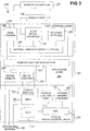
- FIG. 3 is a diagram 300 showing a software architecture 302 for the automation system described in the previous section of the detailed description.
- the software architecture 302 specifically has three layers, a system infrastructure layer 304, an application layer 306, and a user interface layer 308.
- the software architecture 302 is preferably implemented over the system devices 204 of FIG. 2 , such as the devices 176, 178, and 180. An overview of each layer of the architecture 302 is described in turn.
- the architecture 302, which is the central and critical aspect of the software architecture, is then described in more detail.
- the system infrastructure layer 304 includes look-up services 310, a publication/subscription eventing component 312, system management daemons 314, and a soft-state store 316.
- the soft-state store 316 manages the lifetime and replication of soft-state variables.
- the publication/subscription eventing component 312 enables objects, daemons, programs, and other software components to subscribe to events related to changes in the soft-state store 316.
- the look-up services 310 interact with devices and sensors of the automation system, which are indicated by the arrow 318. Specifically, the look-up services 310 include a name-based look-up service (NBLS) 320, and an attribute-based look-up service (ABLS) 322.
- NBLS name-based look-up service
- ABLS attribute-based look-up service
- the ABLS 322 maintains a database of available devices, and supports queries based on device attributes.
- the device attributes can include device type and physical location, among other attributes.
- the NBLS 320 maintains a database of running instances of objects, and supports name-to-object address mapping.
- the system management daemons 314 of the system infrastructure layer 304 detect failures of devices, and initiate recovery actions.
- the application layer 306 includes automation applications 324, device objects 326, and device daemons 328.
- automation applications 324 There are two types of automation applications 324, device-control applications, and sensing applications.
- Device-control applications receive user requests as input, consult the look-up services 310 to identify the devices and the device objects 326 that should be involved, and perform actions on them to satisfy the requests.
- the device objects 326 correspond to the devices and sensors identified by the arrow 318.
- the device objects 326 encapsulate device- and network-specific details of their corresponding devices, and present interfaces for them, such as method calls. Examples of the device objects 326 include camera objects for taking snapshots and recording video clips, and garage door opener objects for operating garage doors.
- Sensing applications monitor environmental factors, and take actions when a monitored event occurs.
- the sensing applications subscribe to events through the eventing component 312.
- Device daemons 328 interact with the devices and sensors identified by the arrow 318, and independently act as proxies for them. For example, a device daemon for a sensor can monitor sensor signals, and update appropriate soft-state variables in the soft-state store 316 to trigger events.
- the user interface layer 308 provides user access to the system infrastructure layer 304 and the application layer 306.
- the user interface layer 308 has three parts, a web browser interface 330, a voice-recognition interface 332, and a text-based natural language parser interface 334.
- the browser interface 330 enables the user to browse through available devices, select devices based on attributes, and control the devices.
- the text-based natural language parser interface 334 is based on a vocabulary appropriate to an automation system, while the voice-recognition interface 332 employs voice recognition technology based on the same vocabulary.
- the user interface layer 308 preferably supports remote automation.
- the browser interface 330 can be used to access the automation system from remote locations.
- the natural language parser interface 334 provides an email-based remote automation interface.
- the email daemon 336 periodically retrieves email through the Internet connection 120, and parses automation-related requests contained in the email.
- the daemon 336 passes the requests to the automation applications 324, and optionally sends reply email confirming that the requested actions have taken place.
- Known digital signature and data encryption technologies can be used to ensure the security of the email. If the user has a mobile phone 338 that supports text messaging, the email daemon 336 can alert the user with text messages when predetermined events occur.
- the voice-recognition interface 332 can optionally be used with the mobile phone 338, or another type of phone.
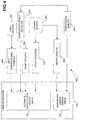
- FIG. 4 is a diagram 400 showing how one embodiment registers devices, sensors, and objects with the look-up services 310.
- the devices and sensors that are registered include the devices and sensors pointed to by the arrow 318 in FIG. 3 .
- the devices include smart devices 208, fixed devices 402, and dynamic devices 404.
- Smart devices 208 are devices that do not need a device adapter to interact with the system.
- Fixed devices 402 are devices that are permanently affixed at their location, and cannot be moved.
- An example of a fixed device is the garage door opener 130 of FIGs. 1 and 2 , which is permanently affixed to a garage wall.
- the fixed devices 402 also include electrical outlets and wall switches.
- Dynamic devices 404 are devices that can be moved.
- An example of a dynamic device is the lamp 168 of FIGs.
- computation objects 406 do not correspond to any particular device, but are used by daemons, applications, and other components of the automation system.
- Example computation objects include language parser objects and voice recognition objects.
- the user performs a one-time manual task of assigning unique addresses to the fixed devices 402, which registers the devices 402 with the ABLS 322.
- the unique address can be X10 addresses. Additional attributes may be entered to associate the devices 402 with physical-location attributes. For example, a wall switch in the garage can be indicated as the "garage wall switch," in addition to having a unique address.
- Dynamic devices 404 have their device attributes announced to the ABLS 322 when they are plugged in and switched on, through the device daemons 328 that act as proxies for the devices 404.
- Device objects 326 for the dynamic devices 404 are instantiated when an application requests to control the devices 404.
- the objects 326 can persist for a length of time, so that repeated requests do not require repeated instantiation.
- the device objects 326 are instantiated by the NBLS 320. Smart devices 208 perform their own registration with the ABLS 322.
- Computation objects 406 are instantiated by the NBLS 320, and require a software component or service referred to as the computation object installer 420 to register with the ABLS 322.
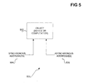
- FIG. 5 is a diagram 500 showing how one embodiment addresses an object 502 in two different ways.
- the object 502 can be one of the device objects 326 of FIG. 4 , or one of the computation objects 406 of FIG. 4 .
- the object 502 has one or more synchronous addresses 304, and one or more asynchronous addresses 306.
- the synchronous addresses 504 can include an address in the form of a marshaled distributed-object interface pointer, or another type of reference that enables real-time communication with the object 502.
- the asynchronous addresses 306 can be in the form of a queue name, a marshaled handle to a queue, or other address.
- the asynchronous addresses 306 are used to asynchronously communicate with the object 502 when it is temporarily unavailable or too busy, or when synchronous communication is otherwise not desired.
- the ABLS 322 of the look-up services 310 maintains a database of available devices and sensors.
- the ABLS 322 supports queries based on combinations of attributes, and returns unique names of the devices and sensors that match the queries. By allowing identification of devices and sensors by their attributes and physical locations, instead of by their unique addresses, the ABLS 322 enables user-friendly device naming. For example, the user can identify a device as "the lamp on the garage side of the kitchen," instead of by its unique address.
- the NBLS 320 of the look-up services 310 maps unique names to object instances identified by those names.
- the NBLS 320 is optionally extensible to allow mapping of a unique name to multiple object instances. Both the ABLS 322 and the NBLS 320 are robust against object failures and non-graceful termination because they are based on the soft-state store 316 of FIG. 3 .
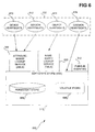
- FIG. 6 is a diagram 600 showing one embodiment of the soft-state store (SSS) 316 in more detail.
- the SSS 316 uses a persistent, or non-volatile, store 608, and a volatile store 606.
- the persistent store 608 is used in addition to the volatile store 606 to save soft-state variables over failures, such as system crashes.
- the persistent store 608 can be a hard disk drive, non-volatile memory such as flash memory, or other non-volatile storage.
- the volatile store 606 can be volatile memory, such as random-access memory, or other volatile storage.
- the SSS 316 ultimately receives heartbeats 602, and stores them as soft-state variables in either the persistent store 608 or the volatile store 606.
- the heartbeats 602 are periodic refreshes from devices, sensors, objects, and daemons, so that the automation system knows they are still operating.
- the heartbeats 602 include device heartbeats 610, sensor heartbeats 612, object heartbeats 614, and daemon heartbeats 616.
- the refresh rates of the heartbeats 602 vary by their type.
- the daemon heartbeats 616 may be received over intervals of seconds.
- the object heartbeats 614 may be received over intervals of tens of seconds to minutes.
- the sensor heartbeats 612 may be received over intervals of minutes to hours.
- the device heartbeats 610 may be received over intervals from hours to days.
- the device heartbeats 610 and the sensor heartbeats 610 are received by the SSS 316 through the ABLS 322, while the object heartbeats 614 are received by the SSS 316 through the NBLS 320.
- the SSS 316 directly receives the daemon heartbeats 616.
- An entity in this context refers to a device, sensor, obj ect, or daemon.
- the SSS 316 preferably performs soft-state variable checkpointing. For a given refresh rate threshold, heartbeats that occur above the threshold, and thus are updated with high frequency, remain in the volatile store 606, to decrease overhead. Recovery of these highfrequency heartbeats from failure of the SSS 316 is through new refreshes. Conversely, heartbeats that occur below the threshold, and thus are updated with low frequency, are persisted in the persistent store 608. Recovery of these low-frequency heartbeats from failure of the SSS 316 is through restoration of the persistent soft-state variables in the store 608. This is because waiting for the next heartbeat may take too long. Downtime of the SSS 316 is preferably treated as missing refreshes for the soft-state variables.
- the publication/subscription eventing component 312 allows subscriptions to events resulting from the change, addition, or deletion of the soft-state variables maintained by the SSS 316.
- the subscribers can include applications, daemons, and other software components of the automation system.
- the eventing component 312 sends events to subscribers when the kinds of changes to the SSS 316 match their corresponding event subscriptions.
- the component 312 receives the changes in the soft-state variables from the SSS 316. From these changes, it formulates events as necessary.
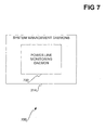
- FIG. 7 is a diagram 700 showing one embodiment of the system management daemons 314 of FIG. 3 in more detail.
- the system management daemons include a power line monitoring daemon 702.
- the power line monitoring daemon 702 detects reliability, security, and other problems with automation system devices that use the power line.
- the daemon 702 can use pattern-based detection for detecting unacceptable power line activity, model-based detection for detecting acceptable power line activity, or both.
- Pattern-based detection employs a database of unacceptable power line patterns that, if detected, trigger an event. For example, faulty devices and external interferences may produce meaningless repetitions or interleaving of commands.
- model-based detection employs a model of acceptable power line patterns. Power line patterns that do not conform to the model also trigger an event.
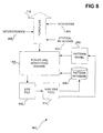
- FIG. 8 is a diagram 800 showing how one embodiment uses the power line monitoring daemon 702 to detect problems on the power line 118.
- the daemon 702 monitors the power line 118 for problems that result from intrusions 802, atypical behaviors 804, and interferences 806.
- the daemon 702 matches patterns from the power line 118 against unacceptable power line patterns stored in the pattern database 808.
- the daemon 702 also tests the patterns against the pattern model 810 of acceptable power line patterns. If matching the patterns against the unacceptable power line patterns stored in the database 808 yields a positive match, or testing the patterns against the model 810 of acceptable power line patterns yields a negative test, the daemon 702 generates an event.
- the event corresponds to the situation that an unacceptable pattern has been detected on the power line 118.
- Other daemons, objects, and programs can subscribe to the event through the eventing component 312, which is not specifically called out in FIG. 8 .
- the monitoring daemon 702 maintains a log file 812 of all detected power line patterns.
- the patterns stored in the log file 812 include both acceptable and unacceptable power line patterns.
- An analysis tool 814 can be used by a user to determine whether to add new unacceptable power line patterns to the database 808, based on the patterns stored in the log file 812. The analysis tool 814 can also be used to determine whether the model 810 of acceptable power line patterns should be modified, based on the patterns stored in the log file 812.
- an instance of the power line monitoring daemon may reside on each of the system devices over which the automation system is implemented. If one of the system devices fails, the redundancy ensures that the automation system itself does not fail.
- a leader daemon instance must be determined. The leader daemon instance is the active instance, which responds to requests to the daemon. The other instances do not respond. If the leader instance fails, then another instance becomes the new leader instance.
- FIG. 9 is a flowchart of a method 900 showing how one embodiment determines which of a number of daemon instances is the leader instance.
- the method 900 is specifically a weak leader election approach. The approach is weak in that only the leader instance knows that it is the leader instance. Other instances only know that they are not the leader instance. Weak leader election reduces the coordination that is necessary among the daemon instances. Requests made to the daemon are multicast to all instances of the daemon, but only the leader instance responds.
- age information is exchanged among all the instances of a daemon.
- the age information can include, for example, how long each instance has been online.
- 904 is performed. Specifically, in 906, each daemon instance determines whether it is the oldest instance, based on the age information received from the other daemon instances in 902. If a daemon instance determines that it is the oldest instance, then, in 908, the instance concludes that it is the leader instance. Otherwise, in 910, the daemon instance concludes that it is not the leader instance.
- the method 900 is periodically repeated, as indicated by the arrow 912. Furthermore, as indicated by the line 914, when any daemon instance has detected that a failure has occurred which may have affected the leader instance, 904 is immediately performed again.
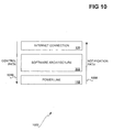
- FIG. 10 is a diagram 1000 showing a high-level view of the architecture.
- the software architecture 302 resides between the power line 118 and the Internet connection 120.
- the architecture 302 abstracts the manner by which the devices connected to the power line 118 are accessed and controlled.
- the Internet connection 120 provides for remote, off-site access and control of devices connected to the power line 118, through the architecture 302.
- the notification path 1008 indicates that notifications from the devices connected to the power line 118 move up to the software architecture 302. The notifications can also move up to the Internet connection 120 in the case of remote, off-site access and control of the devices.
- the control path 1010 indicates that control of the devices originates either from the Internet connection 120 or at the architecture 302, and moves down to the power line 118 to reach the devices.
- FIG. 11 is a flowchart of a method 1100 showing an example operation of the automation system that has been described in the preceding sections of the detailed description.
- the example operation relates to a remote, off-site user emailing a request to close a garage door, and receiving by reply email a confirmation response that the request has been performed.
- the request to perform the close garage door command is received by the automation system in an email over the Internet.
- the email daemon 336 receives the email containing the request through the Internet connection 120.
- the email daemon 336 uses the natural language parser interface 334 to retrieve the command from the text of the email, and relays the command to the appropriate application of the automation applications 324.
- the video camera in the garage is directed to either start recording, if it is a moving-picture camera, or to take a before picture, if it is a still-picture camera.
- the starting of the recording and the taking of the before picture are referred to generally as effecting the video camera a first time.
- the video camera 122 is aimed at the garage door 124 in the garage 1004.
- the video camera 122 begins recording a video clip, or takes a before picture of the garage door 124.
- the appropriate automation application directs the video camera 122 to perform this action through its corresponding device object.
- the device object for the camera 122 is one of the device objects 326 of FIG. 3 . Referring back to FIG.
- the command to close the garage door is performed.
- the garage door opener 130 is used to close the garage door 124.
- the appropriate application directs the device object for the opener 130 to perform this command.
- the device object for the opener 130 is one of the device objects 326 of FIG. 3 .
- the video camera in the garage is directed to either stop recording, or take an after picture, depending on whether it is a moving-picture camera, or a still-picture camera, respectively.
- the stopping of the recording and the taking of the after picture are referred to generally as effecting the video camera a second time.
- the camera 122 stops recording the video clip, or takes an after picture of the garage door 124, as directed by the appropriate application through the object for the camera 122. If the result is a video clip, the clip shows the garage door going from an opened state to a closed state, as the close garage door command is performed. If the result is a before picture and an after picture, the before picture shows the garage door opened, and the after picture shows the garage door closed, after the close garage door command has been performed.
- the remote, off-site user is sent a confirmation response by reply email.
- the appropriate application of the automation applications 324 sends the confirmation response email to the user via the email daemon 336 through the Internet connection 120.
- the response email includes the video clip that has been recorded or the before and after pictures that have been taken.
- timestamps are stamped on the frames of the video clip or on the before and after pictures. The timestamps indicate the relative times during which the close garage door command was performed.
- the timestamp is digitally watermarked in the clip or in the pictures, so malicious doctoring or other modification can be detected.
- Independent verification allows users to witness that a desired command relative to a desired device has been successfully performed.
- Video confirmation is one type of independent verification.
- Independent verification can also include audio confirmation, or other types of confirmation.
- the independent verification can be performed within the user interface layer 308 of FIG. 3 .
- the automation system that has been described with reference to FIGs. 1 and 2 in a previous section of the detailed description includes a device adapter 166 that connects the lamp 168 to the electrical outlet 164.
- Device adapters such as the device adapter 166, are employed in general to allow non-intelligent devices, such as the lamp 168, to be controlled and accessed within the automation system. In particular, the device adapters announce non-intelligent devices and their locations to the automation system.
- the device adapter 166 is used in conjunction with the attribute-based lookup service (ABLS) 322 of FIG. 3 .
- ABLS attribute-based lookup service
- a one-time configuration task is performed by assigning an address to every electrical outlet in the house that the user would like to control, and mapping the address to a unique set of physical location attributes.
- a new device is plugged into an electrical outlet through a device adapter, its device type and the outlet address are announced over the power line to the automation system.
- the user assigns a unique address to each electrical outlet or wall switch, and records the mapping between the physical location and the address in the ABLS 322.
- FIG. 12 is a diagram 1200 showing one embodiment of the device adapter 166 in more detail.
- the user plugs the device into the electrical outlet 1204 of the device adapter 166, and plugs the plug 1202 of the adapter 166 into an electrical outlet.
- the user sets the address of the adapter 166 to match the address of the outlet, by adjusting the controls 1206 of the adapter 166.
- the user also sets the device code and the module code for the device, using the controls 1208 and 1210, respectively.
- the device code is selected from a pre-defined set of device type codes.
- the module code specifies the device object class from which a device object should be instantiated to control the device. As shown in FIG.
- the controls 1206 include two dial switches, while the controls 1208 and 1210 each include one dial switch.
- Other types of controls can be used, such as slider switches and keypads, among others.
- the controls 1206, 1208, and 1210 can alternatively be internal controls that are set remotely through a computer.
- the device adapter 166 broadcasts the device code, the module code, and the address over the power line in the form of an extended code.
- the address and the extended code can be consistent with the known X1 0 protocol.
- the subset of system devices 204 of FIG. 2 that receive the announcement register the device with the ABLS 322 of FIG. 3 , and register their own device daemons 328 of FIG. 3 as the proxies for the device. The proxies can then be employed to instantiate appropriate device objects 326 of FIG. 3 to control the device.
- the device adapter 166 is responsible for sending periodic announcements to the soft-state store (SSS) 316 of FIG. 3 so that the proxies can refresh the soft-state variables for the device.
- SSS soft-state store
- the adapter 166 announces that the device has left the system.
- the adapter 166 itself is unplugged, the periodic refreshes stop and the device's entry in the ABLS 322 of FIG. 3 eventually times out.
- the adapter 166 preferably includes a manual override function so that the user can turn on both the device and the adapter 166 by using a power switch on the device.
- FIG. 13 is a diagram 1300 showing how one embodiment implements the device adapter 166.
- the adapter 166 is connected to the power line 118 by line 1302.
- a non-intelligent device 1314 is connected to the adapter 166 by line 1304.
- the non-intelligent device 1314 can, for example, be the lamp 168 of FIGs. 1 and 2 .
- the adapter 166 has a receiver 1306, a transmitter 1308, a sensor 1310, and a logic mechanism 1312.
- the receiver 1306 and the transmitter 1308 are used to control the non-intelligent device 1314.
- the receiver 1306 receives commands from the power line 118, and can be an X10 receiver that receives X10 commands.
- the receiver 1306 controls electricity from the power line 118 to the device 1314, depending on the received commands.
- the receiver 1306 has an on/off status indicating whether the adapter 166 is plugged into an electrical outlet and receiving power.
- the on/off status has two states, an on state, and an off state. In the on state, the adapter 166 is receiving power, whereas in the off state, the adapter 166 is not receiving power.
- the transmitter 1308 announces joining and leaving of the device 1314 over the power line 118, as instructed by the logic mechanism 1312.
- the receiver 1306 and the transmitter 1308 can be integrated into a single transceiver.
- the logic mechanism 1312 determines when to instruct the transmitter 1308 to announce leaving or joining of the device 1314.
- the device 1314 also has an on/off status having two states, an on state, and an off state.
- the mechanism 1312 detects that the receiver 1306 is on, but the sensor 1310 has not detected electricity flowing through the device 1314, it instructs the transmitter 1308 to announce leaving of the device 1314. This corresponds to the situation where the adapter 166 is plugged into an electrical outlet, is receiving power, and is on, but the device 1314 is off.
- the mechanism 1312 detects that the receiver 1306 is on, and the sensor 1310 has detected electricity flowing through the device 1314, the mechanism instructs the transmitter 1308 to announce joining of the device 1314. This corresponds to the situation where the adapter 166 is plugged into an electrical outlet, is receiving power, and is on, and the device 1314 is also on.
- the sensor 1310 is used to determine whether the device is on, or off or broken.
- the sensor 1310 can be a current sensor, detecting whether electrical current is flowing through the device 1314.
- the logic mechanism 1312 can be implemented as software, hardware, or a combination of software and hardware.
- the logic mechanism 1312 can be a state machine, making decisions regarding when to instruct the transmitter 1308 to announce joining and leaving of the device 1314.
- the invention can be implemented within a computerized environment having one or more computerized devices.
- the diagram of FIG. 14 shows an example computerized device 1400.
- the device 1400 can implement one or more of the system devices 204 of FIG. 2 , or one or more of the user access points 206 of FIG. 2 .
- the example computerized device 1400 can be, for example, a desktop computer, a laptop computer, or a personal digital assistant (PDA).
- PDA personal digital assistant
- the invention may be practiced with other computer system configurations as well, including multiprocessor systems, microprocessor-based or programmable consumer electronics, network computers, minicomputers, and mainframe computers.
- the invention may be practiced in distributed computing environments where tasks are performed by remote processing devices that are linked through a communications network.
- the device 1400 includes one or more of the following components: processor(s) 1402, memory 1404, storage 1406, a communications component 1408, input device(s) 1410, a display 1412, and output device(s) 1414.
- processor(s) 1402 memory 1404, storage 1406, a communications component 1408, input device(s) 1410, a display 1412, and output device(s) 1414.
- processor(s) 1402 memory 1404, storage 1406, a communications component 1408, input device(s) 1410, a display 1412, and output device(s) 1414.
- processor(s) 1402 memory 1404, storage 1406, a communications component 1408, input device(s) 1410, a display 1412, and output device(s) 1414.
- input device(s) 1410 input device(s) 1410
- display 1412 display 1412
- output device(s) 1414 output device(s) 1414.
- output device(s) 1414 output device(s) 1414.
- the description of the device 1400 is to be used
- the processor(s) 1402 may include a single central-processing unit (CPU), or a plurality of processing units, commonly referred to as a parallel processing environment.
- the memory 1404 may include read-only memory (ROM) and/or random-access memory (RAM).
- the storage 1406 may be any type of storage, such as fixed-media storage devices and removable-media storage devices. Examples of the former include hard disk drives, and flash or other non-volatile memory. Examples of the latter include tape drives, optical drives like CD-ROM drives, and floppy disk drives.
- the storage devices and their associated computer-readable media provide non-volatile storage of computer-readable instructions, data structures, program modules, and other data. Any type of computer-readable media that can store data and that is accessible by a computer can be used.
- the device 1400 may operate in a network environment. Examples of networks include the Internet, intranets, extranets, local-area networks (LAN's), and wide-area networks (WAN's).
- the device 1400 may include a communications component 1408, which can be present in or attached to the device 1400.
- the component 1408 may be one or more of a network card, an Ethernet card, an analog modem, a cable modem, a digital subscriber loop (DSL) modem, and an Integrated Services Digital Network (ISDN) adapter.
- the input device(s) 1410 are the mechanisms by which a user provides input to the device 1400. Such device(s) 1410 can include keyboards, pointing devices, microphones, joysticks, game pads, and scanners.
- the display 1412 is how the device 1400 typically shows output to the user.
- the display 1412 can include cathode-ray tube (CRT) display devices and flat-panel display (FPD) display devices.
- the device 1400 may provide output to the user via other output device(s) 1414.
- the output device(s) 1414 can include speakers, printers, and other types of devices.
- a computer-implemented method is desirably realized at least in part as one or more programs running on a computer.
- the programs can be executed from a computer-readable medium such as a memory by a processor of a computer.
- the programs are desirably storable on a machine-readable medium, such as a floppy disk or a CD-ROM, for distribution and installation and execution on another computer.
- the program or programs can be a part of a computer system, a computer, or a computerized device.
Abstract
Description
- This invention relates generally to controlling and monitoring devices and sensors, such as devices and sensors that connect to the power line, and more particularly to an automation system for controlling and monitoring devices and sensors.
- Home networking and automation have become more popular. With the number and complexity of audio/video equipment increasing, some homeowners are interested in operating their equipment more easily. Other homeowners are more concerned about the security and safety of their homes. These homeowners may want to remotely monitor their homes, remotely control appliances and other power line devices, and learn when important events occur. For example, an important event can be the hot water heater bursting or leaking, or another type of event. Power line devices are devices that connect to the power line, usually through a plug that connects to an electrical outlet.
- Currently, there are two popular home networking infrastructures. The first is phone line networking. To provide in-home networking of computers and computer peripherals without requiring home rewiring, as is usually required with standard Ethernet networks, the Home Phone line Networking Alliance (HomePNA) was formed to leverage the existing phone lines in homes. More detailed information regarding the HomePNA can be found on the Internet at www.homepna.com. While phone line networking allows homeowners to create small local-area networks (LAN's) within their homes for the purposes of connecting computers and computer peripherals, it has limitations. Significantly, phone line networking typically does not allow homeowners to control appliances, lamps, and other power line devices within their homes.
- A second home networking infrastructure is power line networking. Power line networking provides ubiquitous wired connectivity throughout the majority of homes. One type of power line networking is known as X10. X10 is a communications protocol that allows for remotely controlling power line devices, such as lamps and appliances. More detailed information regarding the X10 protocol can be found on the Internet at ftp://ftp.scruz.net/users/cichlid/public/x10faq.
- Current power line networking, such as X10 networking, is limited. The X10 protocol, for example, provides only a rudimentary and low-level framework for controlling and monitoring power line devices. The framework generally does not allow for sophisticated and complex device control applications. While automation systems employing existing X10 technology can be implemented using computers, more typically the systems are implemented with relatively less intelligent control centers that only govern a limited number of power line devices, in a limited manner. When computers are used, the resulting systems are still far from ideal. They may be difficult to use, and may not be reliable or robust against equipment failures and crashes.
- For the reasons described here, as well as other reasons, there is a need for the present invention.
-
EP 0 932 275 A describes methods, systems and apparatus for providing device identification within a network. - H. R. RIS, "EIB-BUS-EUROPAISCHER INSTALLATIONSBUS TEIL 2" ELEKTROTECHNIK, VOGEL VERLAG K.G., WURZBURG, no. 7/08, 1993, pages 61 to 67 describes the EIB bus.
-
EP 0 778 684 A relates to locating machines on computer networks. - It is the object of the invention to provide an improved system for controlling and monitoring a plurality of devices.
- This object is solved by the invention as claimed in the independent claims.
- Preferred embodiments are specified in the dependent claims.
- The invention relates to an automation system for controlling and monitoring devices and sensors. The devices can include power line devices, such as lamps, appliances, audio/video equipment, and other devices that connect to the power line of a house or other building. The sensors can include sensors for detecting the occurrence of emergency-related and other events. For example, a water sensor located near a hot water heater can detect whether the heater has burst, or is leaking.
- The invention provides an architecture for controlling and monitoring these devices and sensors in an intelligent, reliable, and robust manner. With respect to intelligence, for example, the architecture includes look-up services that maintain a database of all available devices in a user-friendly manner. Rather than remembering a lamp by an archaic address, a homeowner may simply identify the lamp as "the lamp plugged into the eastern wall of the bedroom." Other aspects of the architecture provide for sophisticated and complex automation applications to intelligently control and monitor devices and sensors.
- With respect to reliability, devices controlled by the system send, or have sent for them, periodic refresh information to indicate that they are properly functioning. The periodic refresh information is referred to as a heartbeat. The architecture includes a soft-state store to store this information, and a publication/subscription eventing component to enable subscriptions to events relating to changes in this information. If a device becomes inoperative, it stops sending heartbeats for the soft-state store to record. Through subscriptions that the eventing component manages, other components within the automation system can become aware that the device is inoperative, and take appropriate recovery action. The architecture can also include a power line monitoring daemon, as well as other system management daemons. The power line monitoring daemon detects suspect behavior on the power line that may indicate that a power line device is malfunctioning, or that a malicious intrusion into the system is being attempted.
- With respect to robustness, the architecture can have built-in redundancy in the number of computers over which the architecture is implemented, as well as in the number of instances of certain types of important system management daemons. Redundant daemon instances utilize a weak-leader approach to determine which among them is the current leader instance that should respond to inquiries made to the daemon. If the leader daemon instance fails, one of the redundant daemon instances becomes the new leader instance, so that the system does not go offline.
- The invention encompasses automation systems, automation system architectures, and methods of varying scopes. Other aspects, embodiments and advantages of the invention, beyond those described here, will become apparent by reading the detailed description and by referencing the drawings.
-
-
FIG. 1 is a pictorial diagram of an example house in which an automation system of the invention can be implemented. -
FIG. 2 is a topological diagram of the automation system ofFIG. 1 . -
FIG. 3 is a diagram of a software architecture that can implement the automation system ofFIGs. 1 and2 . -
FIG. 4 is a diagram showing how devices, sensors, and objects are registered with the look-up services of the software architecture ofFIG. 3 , according to an embodiment of the invention. -
FIG. 5 is a diagram showing how an object ofFIG. 4 can be addressed in two different ways, according to an embodiment of the invention. -
FIG. 6 is a diagram showing the soft-state store ofFIG. 3 in more detail, according to an embodiment of the invention. -
FIG. 7 is a diagram showing a power line monitoring daemon as one example of the system management daemons ofFIG. 3 , according to an embodiment of the invention. -
FIG. 8 is a diagram showing how the power line monitoring daemon ofFIG. 7 detects patterns from the power line, according to an embodiment of the invention. -
FIG. 9 is a flowchart of a weak leader election method by which a number of daemon instances determine which instance is the leader instance, according to an embodiment of the invention. -
FIG. 10 is a diagram showing an abstract, high-level view of the software architecture ofFIG. 3 . -
FIG. 11 is a flowchart of a method showing an example operation of an automation system of an embodiment of the invention. -
FIG. 12 is a diagram showing the device adapter ofFIGs. 1 and2 in more detail, according to an embodiment of the invention. -
FIG. 13 is a diagram showing how the device adapter ofFIGs. 1 and2 can be implemented, according to an embodiment of the invention. -
FIG. 14 is a diagram of an example computerized device that can be used to implement the invention. - In the following detailed description of exemplary embodiments of the invention, reference is made to the accompanying drawings that form a part hereof, and in which is shown by way of illustration specific exemplary embodiments in which the invention may be practiced. These embodiments are described in sufficient detail to enable those skilled in the art to practice the invention. Other embodiments may be utilized, and logical, mechanical, electrical, and other changes may be made without departing from the spirit or scope of the present invention. The following detailed description is, therefore, not to be taken in a limiting sense, and the scope of the present invention is defined only by the appended claims.
-
FIG. 1 shows a pictorial diagram 100 of anexample house 102 in which an automation system of the invention can be implemented. Thehouse 102 includes agarage 104, akitchen 106, afamily room 108, amaster bedroom 110, and aden 114, among other rooms. Connections coming into and distributed throughout thehouse 102 include aphone line 116, apower line 118, and anInternet connection 120. Thephone line 116 allows residents of thehouse 102 to place and receive phone calls. Thepower line 118 provides electrical power to thehouse 102. TheInternet connection 120 connects thehouse 102 to the Internet. TheInternet connection 120 can be a fast, always-on broadband connection, such as a cable modem connection or a Digital Subscriber Loop (DSL) line. TheInternet connection 120 may also be a slow, dial-up connection that utilizes thephone line 116. - Not specifically called out in
FIG. 1 is that a network has been set up within thehouse 102. The network is of the type that connects computers and computer peripherals with one another. For example, the network may be an Ethernet network, using dedicated wiring, or using the existingphone line 116. The network may also be a wireless Ethernet network, or another type of network. For purposes of descriptive clarity, this network is referred to as the backbone network in the detailed description. The backbone network is distinct from a power line network, for example. - Each of the rooms of the
house 102 has a number of network adapters and electrical outlets, as well as other types of components. Thegarage 104 has four components pertinent to the automation system. Thevideo camera 122 allows remote monitoring of whether thegarage door 124 is open or closed. Thecamera 122 is preferably directly connected to the backbone network set up within thehouse 102. Thenetwork adapter 128, as well as other network adapters throughout thehouse 102, provide for connectivity to the backbone network. Thegarage door opener 130 controls the opening and closing of thegarage door 124, and is connected to the backbone network through thenetwork adapter 128. - Electrical power devices that may be controlled using the automation system can be plugged into the
electrical outlet 126, or into other electrical outlets throughout thehouse 102. Electrical power devices are also referred to as power line devices. Power line devices include appliances, lamps, audio/video equipment, and other types of devices that are plugged into electrical outlets. The power line devices are typically independent from one another. For example, a power line device that is a lamp is independent from a power line device that is a clock radio, in that the lamp and the clock radio are not aware of each other. The lamp and the clock radio can each be independently controlled by the automation system. - In an
alcove 132 off thegarage 104, there is ahot water heater 134 and afurnace 136. Relevant to the automation system is thewater sensor 138, which is connected to the backbone network through thenetwork adapter 140. Thewater sensor 138 is located on the floor of thealcove 132 and detects the presence water, which may indicate that thehot water heater 134 is leaking or has burst. - The
kitchen 106 likewise has anelectrical outlet 138 and anetwork adapter 140. As shown inFIG. 1 , the kitchen also includes a radio-frequency (RF)device 142. TheRF device 142 communicates with anRF bridge 144 that is wired to the backbone network. An example of theRF device 142 is a wireless temperature gauge that periodically sends the detected temperature via RF signals to theRF bridge 144. Theden 114 in particular includes theRF bridge 144, connected to the backbone network through thenetwork adapter 146, with which theRF device 142 communicates. Thefamily room 108 also has anRF device 148. TheRF bridge 144 receives RF signals transmitted by theRF devices house 102 via thenetwork adapter 146. TheRF bridge 144 also receives data from the backbone network intended for theRF devices devices - A user access point (UAP) 101 is located in the
kitchen 106. TheUAP 101, and other UAP's throughout thehouse 102, permit users of the automation system to interact with the system. TheUAP 101 can be a touch-screen, flat-screen device mounted on a wall of thekitchen 106. The user provides input to the automation system by touching the device, and receives output from the system by viewing the screen of the device. TheUAP 101 can also be a computer, or another type of device. - The
family room 108, in addition to theRF device 148, includeselectrical outlets network adapter 154. Audio/video (A/V)devices 156 are connected to an A/V bridge 158, through which the A/V devices 156 can send and receive audio, video, and control signals through the backbone network set up in thehouse 102. The A/V bridge 158 is connected to the backbone network through thenetwork adapter 154. Thefamily room 108 has athermostat 160 for controlling the heating and cooling system of thehouse 102. The heating and cooling system includes, for example, thefurnace 136 in thealcove 132 off thegarage 104. Thethermostat 160 is preferably connected directly to the backbone network set up in thehouse 102. AUAP 103 is also located in thefamily room 108. - The
master bedroom 110 has anetwork adapter 162 and anelectrical outlet 164. Of particular relevance to the automation system is that adevice adapter 166 is directly plugged into theelectrical outlet 164, and alamp 168 is plugged into thedevice adapter 166. Thedevice adapter 166 allows the automation system to control non-intelligent power devices, such as thelamp 168. A subsequent section of the detailed description describes the construction and the use of thedevice adapter 166. AUAP 105 is also located in themaster bedroom 110. - The
den 114 is the room of thehouse 102 in which the heart of the automation system is located. There are fourcomputing devices computing device 174 serves as the gateway device, through which the backbone network set up in thehouse 102 is connected to theInternet connection 120. Thedevices devices network adapter 182, and can receive power through the electrical outlet 184. - The four
computing devices house 102, instead of in a single room, such as theden 114. This may be desirable where one or more of these computing devices also serves as a UAP. Furthermore, if a circuit breaker for the room where one of the computing devices is located trips, only one computing device is affected. The automation system will still be able to operate over the other, unaffected computing devices. - The
RF bridge 144 of theden 114 allows theRF devices kitchen 106 and thefamily room 108, respectively, to communicate with other devices on the backbone network set up in thehouse 102. TheRF bridge 144 is connected to the backbone network through thenetwork adapter 146, and receives power through the electrical outlet 186. There are two other bridges in theden 114, theIR bridge 188, and thepower bridge 192. The infrared (IR)bridge 188 allows theIR device 190, and other IR devices, to communicate with devices on the backbone network. TheIR device 190 sends IR signals to and receives IR signals from theIR bridge 188, and vice-versa. Examples of theIR device 190 include a video-cassette recorder (VCR) and a remote control, although thedevice 190 can be any type of device. IR signals differ from RF signals in that they require a direct line of sight between the sender and the receiver, unlike RF signals. TheIR bridge 188 receives power from theelectrical outlet 194, and is connected to the backbone network through thenetwork adapter 196. - The
power bridge 192 allows devices connected to thepower line 118 of thehouse 102 via electrical outlets to communicate with devices on the backbone network. Thepower bridge 192 is connected to the backbone network through thenetwork adapter 182, and through theelectrical outlet 198 receives power and communicates with the devices connected to thepower line 118. For example, thelamp 168 in themaster bedroom 110 can be controlled and monitored by the automation system. Thedevice adapter 166 situated between thelamp 168 and theelectrical outlet 164 sends and receives signals over thepower line 118. Thepower bridge 192 transfers these signals from thepower line 118 to the backbone network set up in thehouse 102. - While the automation system has been shown in
FIG. 1 as implemented in a house, the system can also be implemented in other types of buildings as well. For example, the automation system can be implemented in an office building, a church, a store, a mall, or another type of building. The automation system can also be implemented without regard to a physical structure, such as a building. The components controlled and used by the automation system ofFIG. 1 are representative components, and are not all required to practice the invention. As an example, theIR device 190 and theRF devices -
FIG. 2 shows a diagrammatic topology of the automation system ofFIG. 1 , providing another view of the system. The automation system is called out as thesystem 200 inFIG. 2 . Thebackbone network 202 is preferably an Ethernet network, implemented over a dedicated line or over thephone line 116 ofFIG. 1 . Thesystem devices 204 include thedevices devices 204 connect to thebackbone network 202 through thenetwork adapter 182. Thedevice 174 is the gateway device that connects to theInternet connection 120. The user access points (UAP's) 206 include the UAP's 101, 103, and 105. The UAP's 206 are preferably directly connected to thebackbone network 202. Likewise, thethermostat 160 is directly connected to thebackbone network 202, whereas thewater sensor 138 is connected to thebackbone network 202 through thenetwork adapter 140. The audio/video (A/V)devices 156 are connected to the A/V bridge 158, which is connected to thebackbone network 202 through thenetwork adapter 154. The A/V bridge 158 enables the A/V devices 156 to communicate with devices on thebackbone network 202. - The
power bridge 192 is connected to thebackbone network 202 through thenetwork adapter 182. Two instances of thesame network adapter 182 are shown inFIG. 2 for illustrative clarity. Thepower bridge 192 is connected to thepower line 118 through theelectrical outlet 198.Smart power devices 208 directly connect to thepower line 118 through correspondingelectrical outlets 210, and can directly communicate with thepower bridge 192. By comparison, non-intelligent power devices require interstitial device adapters between them and their corresponding electrical outlets. For example, thelamp 168 requires thedevice adapter 166 between it and theelectrical outlet 164 for the automation system to control and monitor thelamp 168. Moving to the right of thepower bridge 192 on thebackbone network 202 inFIG. 2 , thegarage door opener 130 is connected to thebackbone network 202 through thenetwork adapter 128. Thevideo camera 122 is directly connected to thebackbone network 202. - The infrared (IR)
bridge 188 is connected to thebackbone network 202 through thenetwork adapter 196, while the radio frequency (RF)bridge 144 is connected to thebackbone network 202 through thenetwork adapter 146. TheIR bridge 188 enables theIR devices 212, such as theIR device 192, to communicate with devices on thebackbone network 202. Likewise, theRF bridge 144 enables theRF devices 214, such as theRF devices backbone network 202. -
FIG. 3 is a diagram 300 showing asoftware architecture 302 for the automation system described in the previous section of the detailed description. Thesoftware architecture 302 specifically has three layers, asystem infrastructure layer 304, anapplication layer 306, and auser interface layer 308. Thesoftware architecture 302 is preferably implemented over thesystem devices 204 ofFIG. 2 , such as thedevices architecture 302 is described in turn. Thearchitecture 302, which is the central and critical aspect of the software architecture, is then described in more detail. - The
system infrastructure layer 304 includes look-upservices 310, a publication/subscription eventing component 312,system management daemons 314, and a soft-state store 316. The soft-state store 316 manages the lifetime and replication of soft-state variables. The publication/subscription eventing component 312 enables objects, daemons, programs, and other software components to subscribe to events related to changes in the soft-state store 316. The look-upservices 310 interact with devices and sensors of the automation system, which are indicated by thearrow 318. Specifically, the look-upservices 310 include a name-based look-up service (NBLS) 320, and an attribute-based look-up service (ABLS) 322. TheABLS 322 maintains a database of available devices, and supports queries based on device attributes. The device attributes can include device type and physical location, among other attributes. TheNBLS 320 maintains a database of running instances of objects, and supports name-to-object address mapping. Thesystem management daemons 314 of thesystem infrastructure layer 304 detect failures of devices, and initiate recovery actions. - The
application layer 306 includesautomation applications 324, device objects 326, anddevice daemons 328. There are two types ofautomation applications 324, device-control applications, and sensing applications. Device-control applications receive user requests as input, consult the look-upservices 310 to identify the devices and the device objects 326 that should be involved, and perform actions on them to satisfy the requests. The device objects 326 correspond to the devices and sensors identified by thearrow 318. The device objects 326 encapsulate device- and network-specific details of their corresponding devices, and present interfaces for them, such as method calls. Examples of the device objects 326 include camera objects for taking snapshots and recording video clips, and garage door opener objects for operating garage doors. - Sensing applications monitor environmental factors, and take actions when a monitored event occurs. The sensing applications subscribe to events through the
eventing component 312.Device daemons 328 interact with the devices and sensors identified by thearrow 318, and independently act as proxies for them. For example, a device daemon for a sensor can monitor sensor signals, and update appropriate soft-state variables in the soft-state store 316 to trigger events. - The
user interface layer 308 provides user access to thesystem infrastructure layer 304 and theapplication layer 306. Theuser interface layer 308 has three parts, aweb browser interface 330, a voice-recognition interface 332, and a text-based naturallanguage parser interface 334. Thebrowser interface 330 enables the user to browse through available devices, select devices based on attributes, and control the devices. The text-based naturallanguage parser interface 334 is based on a vocabulary appropriate to an automation system, while the voice-recognition interface 332 employs voice recognition technology based on the same vocabulary. - The
user interface layer 308 preferably supports remote automation. For example, when theInternet connection 120 is an always-on connection, thebrowser interface 330 can be used to access the automation system from remote locations. The naturallanguage parser interface 334 provides an email-based remote automation interface. Theemail daemon 336 periodically retrieves email through theInternet connection 120, and parses automation-related requests contained in the email. Thedaemon 336 passes the requests to theautomation applications 324, and optionally sends reply email confirming that the requested actions have taken place. Known digital signature and data encryption technologies can be used to ensure the security of the email. If the user has amobile phone 338 that supports text messaging, theemail daemon 336 can alert the user with text messages when predetermined events occur. The voice-recognition interface 332 can optionally be used with themobile phone 338, or another type of phone. -
FIG. 4 is a diagram 400 showing how one embodiment registers devices, sensors, and objects with the look-upservices 310. The devices and sensors that are registered include the devices and sensors pointed to by thearrow 318 inFIG. 3 . The devices includesmart devices 208, fixeddevices 402, anddynamic devices 404.Smart devices 208 are devices that do not need a device adapter to interact with the system.Fixed devices 402 are devices that are permanently affixed at their location, and cannot be moved. An example of a fixed device is thegarage door opener 130 ofFIGs. 1 and2 , which is permanently affixed to a garage wall. The fixeddevices 402 also include electrical outlets and wall switches.Dynamic devices 404 are devices that can be moved. An example of a dynamic device is thelamp 168 ofFIGs. 1 and2 , which can be unplugged from one room and moved to another room. The objects that are registered include the device objects 326 ofFIG. 3 , as well as computation objects 406. Computation objects 406 do not correspond to any particular device, but are used by daemons, applications, and other components of the automation system. Example computation objects include language parser objects and voice recognition objects. - Through the
ABLS administration console 408, the user performs a one-time manual task of assigning unique addresses to the fixeddevices 402, which registers thedevices 402 with theABLS 322. The unique address can be X10 addresses. Additional attributes may be entered to associate thedevices 402 with physical-location attributes. For example, a wall switch in the garage can be indicated as the "garage wall switch," in addition to having a unique address.Dynamic devices 404 have their device attributes announced to theABLS 322 when they are plugged in and switched on, through thedevice daemons 328 that act as proxies for thedevices 404. Device objects 326 for thedynamic devices 404 are instantiated when an application requests to control thedevices 404. Theobjects 326 can persist for a length of time, so that repeated requests do not require repeated instantiation. The device objects 326 are instantiated by theNBLS 320.Smart devices 208 perform their own registration with theABLS 322. Computation objects 406 are instantiated by theNBLS 320, and require a software component or service referred to as thecomputation object installer 420 to register with theABLS 322. -
FIG. 5 is a diagram 500 showing how one embodiment addresses anobject 502 in two different ways. Theobject 502 can be one of the device objects 326 ofFIG. 4 , or one of the computation objects 406 ofFIG. 4 . Theobject 502 has one or moresynchronous addresses 304, and one or more asynchronous addresses 306. The synchronous addresses 504 can include an address in the form of a marshaled distributed-object interface pointer, or another type of reference that enables real-time communication with theobject 502. The asynchronous addresses 306 can be in the form of a queue name, a marshaled handle to a queue, or other address. The asynchronous addresses 306 are used to asynchronously communicate with theobject 502 when it is temporarily unavailable or too busy, or when synchronous communication is otherwise not desired. - Referring back to
FIG. 4 , in summary, theABLS 322 of the look-upservices 310 maintains a database of available devices and sensors. TheABLS 322 supports queries based on combinations of attributes, and returns unique names of the devices and sensors that match the queries. By allowing identification of devices and sensors by their attributes and physical locations, instead of by their unique addresses, theABLS 322 enables user-friendly device naming. For example, the user can identify a device as "the lamp on the garage side of the kitchen," instead of by its unique address. TheNBLS 320 of the look-upservices 310 maps unique names to object instances identified by those names. TheNBLS 320 is optionally extensible to allow mapping of a unique name to multiple object instances. Both theABLS 322 and theNBLS 320 are robust against object failures and non-graceful termination because they are based on the soft-state store 316 ofFIG. 3 . -
FIG. 6 is a diagram 600 showing one embodiment of the soft-state store (SSS) 316 in more detail. TheSSS 316 uses a persistent, or non-volatile,store 608, and avolatile store 606. Thepersistent store 608 is used in addition to thevolatile store 606 to save soft-state variables over failures, such as system crashes. Thepersistent store 608 can be a hard disk drive, non-volatile memory such as flash memory, or other non-volatile storage. Thevolatile store 606 can be volatile memory, such as random-access memory, or other volatile storage. - The
SSS 316 ultimately receivesheartbeats 602, and stores them as soft-state variables in either thepersistent store 608 or thevolatile store 606. Theheartbeats 602 are periodic refreshes from devices, sensors, objects, and daemons, so that the automation system knows they are still operating. Theheartbeats 602 includedevice heartbeats 610,sensor heartbeats 612, objectheartbeats 614, anddaemon heartbeats 616. The refresh rates of theheartbeats 602 vary by their type. Thedaemon heartbeats 616 may be received over intervals of seconds. The object heartbeats 614 may be received over intervals of tens of seconds to minutes. Thesensor heartbeats 612 may be received over intervals of minutes to hours. The device heartbeats 610 may be received over intervals from hours to days. - The device heartbeats 610 and the
sensor heartbeats 610 are received by theSSS 316 through theABLS 322, while theobject heartbeats 614 are received by theSSS 316 through theNBLS 320. TheSSS 316 directly receives thedaemon heartbeats 616. When an entity does not send a heartbeat as required by its refresh rate, the entity ultimately times out and is removed from theABLS 322 and theNBLS 320. An entity in this context refers to a device, sensor, obj ect, or daemon. - The
SSS 316 preferably performs soft-state variable checkpointing. For a given refresh rate threshold, heartbeats that occur above the threshold, and thus are updated with high frequency, remain in thevolatile store 606, to decrease overhead. Recovery of these highfrequency heartbeats from failure of theSSS 316 is through new refreshes. Conversely, heartbeats that occur below the threshold, and thus are updated with low frequency, are persisted in thepersistent store 608. Recovery of these low-frequency heartbeats from failure of theSSS 316 is through restoration of the persistent soft-state variables in thestore 608. This is because waiting for the next heartbeat may take too long. Downtime of theSSS 316 is preferably treated as missing refreshes for the soft-state variables. - The publication/
subscription eventing component 312 allows subscriptions to events resulting from the change, addition, or deletion of the soft-state variables maintained by theSSS 316. The subscribers can include applications, daemons, and other software components of the automation system. Theeventing component 312 sends events to subscribers when the kinds of changes to theSSS 316 match their corresponding event subscriptions. Thecomponent 312 receives the changes in the soft-state variables from theSSS 316. From these changes, it formulates events as necessary. -
FIG. 7 is a diagram 700 showing one embodiment of thesystem management daemons 314 ofFIG. 3 in more detail. In particular, the system management daemons include a powerline monitoring daemon 702. The powerline monitoring daemon 702 detects reliability, security, and other problems with automation system devices that use the power line. Thedaemon 702 can use pattern-based detection for detecting unacceptable power line activity, model-based detection for detecting acceptable power line activity, or both. Pattern-based detection employs a database of unacceptable power line patterns that, if detected, trigger an event. For example, faulty devices and external interferences may produce meaningless repetitions or interleaving of commands. By comparison, model-based detection employs a model of acceptable power line patterns. Power line patterns that do not conform to the model also trigger an event. -
FIG. 8 is a diagram 800 showing how one embodiment uses the powerline monitoring daemon 702 to detect problems on thepower line 118. Thedaemon 702 monitors thepower line 118 for problems that result fromintrusions 802,atypical behaviors 804, and interferences 806. Thedaemon 702 matches patterns from thepower line 118 against unacceptable power line patterns stored in thepattern database 808. Thedaemon 702 also tests the patterns against thepattern model 810 of acceptable power line patterns. If matching the patterns against the unacceptable power line patterns stored in thedatabase 808 yields a positive match, or testing the patterns against themodel 810 of acceptable power line patterns yields a negative test, thedaemon 702 generates an event. The event corresponds to the situation that an unacceptable pattern has been detected on thepower line 118. Other daemons, objects, and programs can subscribe to the event through theeventing component 312, which is not specifically called out inFIG. 8 . - The
monitoring daemon 702 maintains alog file 812 of all detected power line patterns. The patterns stored in thelog file 812 include both acceptable and unacceptable power line patterns. Ananalysis tool 814 can be used by a user to determine whether to add new unacceptable power line patterns to thedatabase 808, based on the patterns stored in thelog file 812. Theanalysis tool 814 can also be used to determine whether themodel 810 of acceptable power line patterns should be modified, based on the patterns stored in thelog file 812. - For each system management and other daemon, there can be more than one instance of the daemon for redundancy purposes. For example, an instance of the power line monitoring daemon may reside on each of the system devices over which the automation system is implemented. If one of the system devices fails, the redundancy ensures that the automation system itself does not fail. For a number of instances of the same daemon, a leader daemon instance must be determined. The leader daemon instance is the active instance, which responds to requests to the daemon. The other instances do not respond. If the leader instance fails, then another instance becomes the new leader instance.
-
FIG. 9 is a flowchart of amethod 900 showing how one embodiment determines which of a number of daemon instances is the leader instance. Themethod 900 is specifically a weak leader election approach. The approach is weak in that only the leader instance knows that it is the leader instance. Other instances only know that they are not the leader instance. Weak leader election reduces the coordination that is necessary among the daemon instances. Requests made to the daemon are multicast to all instances of the daemon, but only the leader instance responds. - In 902, age information is exchanged among all the instances of a daemon. The age information can include, for example, how long each instance has been online. At each instance, 904 is performed. Specifically, in 906, each daemon instance determines whether it is the oldest instance, based on the age information received from the other daemon instances in 902. If a daemon instance determines that it is the oldest instance, then, in 908, the instance concludes that it is the leader instance. Otherwise, in 910, the daemon instance concludes that it is not the leader instance. The
method 900 is periodically repeated, as indicated by thearrow 912. Furthermore, as indicated by the line 914, when any daemon instance has detected that a failure has occurred which may have affected the leader instance, 904 is immediately performed again. - As a summary of the software architecture described in this section of the detailed description,
FIG. 10 is a diagram 1000 showing a high-level view of the architecture. Thesoftware architecture 302 resides between thepower line 118 and theInternet connection 120. Thearchitecture 302 abstracts the manner by which the devices connected to thepower line 118 are accessed and controlled. TheInternet connection 120 provides for remote, off-site access and control of devices connected to thepower line 118, through thearchitecture 302. Thenotification path 1008 indicates that notifications from the devices connected to thepower line 118 move up to thesoftware architecture 302. The notifications can also move up to theInternet connection 120 in the case of remote, off-site access and control of the devices. Thecontrol path 1010 indicates that control of the devices originates either from theInternet connection 120 or at thearchitecture 302, and moves down to thepower line 118 to reach the devices. -
FIG. 11 is a flowchart of amethod 1100 showing an example operation of the automation system that has been described in the preceding sections of the detailed description. The example operation relates to a remote, off-site user emailing a request to close a garage door, and receiving by reply email a confirmation response that the request has been performed. In 1102, the request to perform the close garage door command is received by the automation system in an email over the Internet. For example, referring toFIG. 3 , theemail daemon 336 receives the email containing the request through theInternet connection 120. Theemail daemon 336 uses the naturallanguage parser interface 334 to retrieve the command from the text of the email, and relays the command to the appropriate application of theautomation applications 324. - Referring back to
FIG. 11 , in 1104, the video camera in the garage is directed to either start recording, if it is a moving-picture camera, or to take a before picture, if it is a still-picture camera. The starting of the recording and the taking of the before picture are referred to generally as effecting the video camera a first time. For example, referring toFIG. 1 , thevideo camera 122 is aimed at thegarage door 124 in the garage 1004. Thevideo camera 122 begins recording a video clip, or takes a before picture of thegarage door 124. The appropriate automation application directs thevideo camera 122 to perform this action through its corresponding device object. The device object for thecamera 122 is one of the device objects 326 ofFIG. 3 . Referring back toFIG. 11 , in 1106, the command to close the garage door is performed. For example, referring toFIG. 1 , thegarage door opener 130 is used to close thegarage door 124. The appropriate application directs the device object for theopener 130 to perform this command. The device object for theopener 130 is one of the device objects 326 ofFIG. 3 . - Referring back to
FIG. 11 , in 1108, the video camera in the garage is directed to either stop recording, or take an after picture, depending on whether it is a moving-picture camera, or a still-picture camera, respectively. The stopping of the recording and the taking of the after picture are referred to generally as effecting the video camera a second time. For example, referring toFIG. 1 , thecamera 122 stops recording the video clip, or takes an after picture of thegarage door 124, as directed by the appropriate application through the object for thecamera 122. If the result is a video clip, the clip shows the garage door going from an opened state to a closed state, as the close garage door command is performed. If the result is a before picture and an after picture, the before picture shows the garage door opened, and the after picture shows the garage door closed, after the close garage door command has been performed. - Referring back to
FIG. 11 , in 1110, the remote, off-site user is sent a confirmation response by reply email. For example, referring toFIG. 3 , the appropriate application of theautomation applications 324 sends the confirmation response email to the user via theemail daemon 336 through theInternet connection 120. The response email includes the video clip that has been recorded or the before and after pictures that have been taken. In an alternative embodiment, timestamps are stamped on the frames of the video clip or on the before and after pictures. The timestamps indicate the relative times during which the close garage door command was performed. In another alternative embodiment, the timestamp is digitally watermarked in the clip or in the pictures, so malicious doctoring or other modification can be detected. - The example operation described is one type of independent verification that can be accomplished by the automation system. Independent verification allows users to witness that a desired command relative to a desired device has been successfully performed. Video confirmation is one type of independent verification. Independent verification can also include audio confirmation, or other types of confirmation. The independent verification can be performed within the
user interface layer 308 ofFIG. 3 . - The automation system that has been described with reference to
FIGs. 1 and2 in a previous section of the detailed description includes adevice adapter 166 that connects thelamp 168 to theelectrical outlet 164. Device adapters, such as thedevice adapter 166, are employed in general to allow non-intelligent devices, such as thelamp 168, to be controlled and accessed within the automation system. In particular, the device adapters announce non-intelligent devices and their locations to the automation system. - The
device adapter 166 is used in conjunction with the attribute-based lookup service (ABLS) 322 ofFIG. 3 . To minimize user administration, a one-time configuration task is performed by assigning an address to every electrical outlet in the house that the user would like to control, and mapping the address to a unique set of physical location attributes. When a new device is plugged into an electrical outlet through a device adapter, its device type and the outlet address are announced over the power line to the automation system. To perform the one-time configuration task, the user assigns a unique address to each electrical outlet or wall switch, and records the mapping between the physical location and the address in theABLS 322. For example, when the address "A5" is assigned to an outlet on the backyard side of the kitchen on the first floor, the entry "address = A5; floor = one; room = kitchen; side = backyard" is recorded. Once an electrical outlet is assigned an address, a device adapter plugged into the outlet is also set to the address. -
FIG. 12 is a diagram 1200 showing one embodiment of thedevice adapter 166 in more detail. To add a non-intelligent device to the system, after having performed the one-time configuration task, the user plugs the device into theelectrical outlet 1204 of thedevice adapter 166, and plugs theplug 1202 of theadapter 166 into an electrical outlet. The user sets the address of theadapter 166 to match the address of the outlet, by adjusting thecontrols 1206 of theadapter 166. The user also sets the device code and the module code for the device, using thecontrols FIG. 12 , thecontrols 1206 include two dial switches, while thecontrols controls - When the non-intelligent device that has been plugged into the
outlet 1204 of theadapter 166 is switched on, thedevice adapter 166 broadcasts the device code, the module code, and the address over the power line in the form of an extended code. The address and the extended code can be consistent with the known X1 0 protocol. The subset ofsystem devices 204 ofFIG. 2 that receive the announcement register the device with theABLS 322 ofFIG. 3 , and register theirown device daemons 328 ofFIG. 3 as the proxies for the device. The proxies can then be employed to instantiate appropriate device objects 326 ofFIG. 3 to control the device. - The
device adapter 166 is responsible for sending periodic announcements to the soft-state store (SSS) 316 ofFIG. 3 so that the proxies can refresh the soft-state variables for the device. When the device is broken or unplugged from theadapter 166, theadapter 166 announces that the device has left the system. When theadapter 166 itself is unplugged, the periodic refreshes stop and the device's entry in theABLS 322 ofFIG. 3 eventually times out. Theadapter 166 preferably includes a manual override function so that the user can turn on both the device and theadapter 166 by using a power switch on the device. -
FIG. 13 is a diagram 1300 showing how one embodiment implements thedevice adapter 166. Theadapter 166 is connected to thepower line 118 byline 1302. Anon-intelligent device 1314 is connected to theadapter 166 byline 1304. Thenon-intelligent device 1314 can, for example, be thelamp 168 ofFIGs. 1 and2 . Theadapter 166 has areceiver 1306, atransmitter 1308, asensor 1310, and alogic mechanism 1312. Thereceiver 1306 and thetransmitter 1308 are used to control thenon-intelligent device 1314. Thereceiver 1306 receives commands from thepower line 118, and can be an X10 receiver that receives X10 commands. Thereceiver 1306 controls electricity from thepower line 118 to thedevice 1314, depending on the received commands. Thereceiver 1306 has an on/off status indicating whether theadapter 166 is plugged into an electrical outlet and receiving power. The on/off status has two states, an on state, and an off state. In the on state, theadapter 166 is receiving power, whereas in the off state, theadapter 166 is not receiving power. Thetransmitter 1308 announces joining and leaving of thedevice 1314 over thepower line 118, as instructed by thelogic mechanism 1312. Thereceiver 1306 and thetransmitter 1308 can be integrated into a single transceiver. - The
logic mechanism 1312 determines when to instruct thetransmitter 1308 to announce leaving or joining of thedevice 1314. Thedevice 1314 also has an on/off status having two states, an on state, and an off state. When themechanism 1312 detects that thereceiver 1306 is on, but thesensor 1310 has not detected electricity flowing through thedevice 1314, it instructs thetransmitter 1308 to announce leaving of thedevice 1314. This corresponds to the situation where theadapter 166 is plugged into an electrical outlet, is receiving power, and is on, but thedevice 1314 is off. When themechanism 1312 detects that thereceiver 1306 is on, and thesensor 1310 has detected electricity flowing through thedevice 1314, the mechanism instructs thetransmitter 1308 to announce joining of thedevice 1314. This corresponds to the situation where theadapter 166 is plugged into an electrical outlet, is receiving power, and is on, and thedevice 1314 is also on. - The
sensor 1310 is used to determine whether the device is on, or off or broken. Thesensor 1310 can be a current sensor, detecting whether electrical current is flowing through thedevice 1314. Thelogic mechanism 1312 can be implemented as software, hardware, or a combination of software and hardware. Thelogic mechanism 1312 can be a state machine, making decisions regarding when to instruct thetransmitter 1308 to announce joining and leaving of thedevice 1314. - The invention can be implemented within a computerized environment having one or more computerized devices. The diagram of
FIG. 14 shows an examplecomputerized device 1400. Thedevice 1400 can implement one or more of thesystem devices 204 ofFIG. 2 , or one or more of theuser access points 206 ofFIG. 2 . The examplecomputerized device 1400 can be, for example, a desktop computer, a laptop computer, or a personal digital assistant (PDA). The invention may be practiced with other computer system configurations as well, including multiprocessor systems, microprocessor-based or programmable consumer electronics, network computers, minicomputers, and mainframe computers. The invention may be practiced in distributed computing environments where tasks are performed by remote processing devices that are linked through a communications network. - The
device 1400 includes one or more of the following components: processor(s) 1402,memory 1404,storage 1406, acommunications component 1408, input device(s) 1410, adisplay 1412, and output device(s) 1414. For a particular instantiation of thedevice 1400, one or more of these components may not be present. For example, a PDA may not have any output device(s) 1414. The description of thedevice 1400 is to be used as an overview of the types of components that typically reside within such a device, and is not meant as a limiting or exhaustive description. - The processor(s) 1402 may include a single central-processing unit (CPU), or a plurality of processing units, commonly referred to as a parallel processing environment. The
memory 1404 may include read-only memory (ROM) and/or random-access memory (RAM). Thestorage 1406 may be any type of storage, such as fixed-media storage devices and removable-media storage devices. Examples of the former include hard disk drives, and flash or other non-volatile memory. Examples of the latter include tape drives, optical drives like CD-ROM drives, and floppy disk drives. The storage devices and their associated computer-readable media provide non-volatile storage of computer-readable instructions, data structures, program modules, and other data. Any type of computer-readable media that can store data and that is accessible by a computer can be used. - The
device 1400 may operate in a network environment. Examples of networks include the Internet, intranets, extranets, local-area networks (LAN's), and wide-area networks (WAN's). Thedevice 1400 may include acommunications component 1408, which can be present in or attached to thedevice 1400. Thecomponent 1408 may be one or more of a network card, an Ethernet card, an analog modem, a cable modem, a digital subscriber loop (DSL) modem, and an Integrated Services Digital Network (ISDN) adapter. The input device(s) 1410 are the mechanisms by which a user provides input to thedevice 1400. Such device(s) 1410 can include keyboards, pointing devices, microphones, joysticks, game pads, and scanners. Thedisplay 1412 is how thedevice 1400 typically shows output to the user. Thedisplay 1412 can include cathode-ray tube (CRT) display devices and flat-panel display (FPD) display devices. Thedevice 1400 may provide output to the user via other output device(s) 1414. The output device(s) 1414 can include speakers, printers, and other types of devices. - The methods that have been described can be computer-implemented on the
device 1400. A computer-implemented method is desirably realized at least in part as one or more programs running on a computer. The programs can be executed from a computer-readable medium such as a memory by a processor of a computer. The programs are desirably storable on a machine-readable medium, such as a floppy disk or a CD-ROM, for distribution and installation and execution on another computer. The program or programs can be a part of a computer system, a computer, or a computerized device. - It is noted that, although specific embodiments have been illustrated and described herein, it will be appreciated by those of ordinary skill in the art that any arrangement that is calculated to achieve the same purpose may be substituted for the specific embodiments shown. This application is intended to cover any adaptations or variations of the present invention. Therefore, it is manifestly intended that this invention be limited only by the claims and equivalents thereof.
Claims (24)
- A system (300) for controlling and monitoring a plurality of devices (318), the system
characterized by:at least one look-up service (310) containing at least one device attribute corresponding to each of the devices, and containing a plurality of device objects corresponding to at least some of the devices, the look up service determining at least one device attribute and/or object corresponding to an input from a user or sensor and a corresponding one of the objects and/or devices associated with the attribute performing an action in response to the input;a soft-state store (316) to manage at least periodic refresh information transmitted by the plurality of devices and the plurality of device objects, the refresh information managed by the soft-state store as a plurality of soft-state variables, the refresh information indicating the current operational states of the respective devices and objects; anda publication/subscription eventing component (312) for determining events related to changes in the plurality of soft-state variables managed by the soft-state store, the events affecting the action of at least some of the devices and/or objects, - The system of claim 1, wherein the at least one look-up service is characterized by:an attribute-based look-up service (322) to maintain a first database of the plurality of devices by the plurality of device attributes; and,a name-based look-up service (320) to maintain a second database of the plurality of device objects corresponding to the plurality of devices.
- The system of claim 2, wherein the name-based look-up service instantiates instances of the plurality of device objects.
- The system of claim 2, wherein the second database maintained by the name-based look-up service further includes a plurality of computation objects.
- The system of claim 1, wherein the at least one address for each device object is characterized by a synchronous address for synchronous communication with the device object, and an asynchronous address for asynchronous communication with the device object.
- The system of claim 1, wherein the device and the device object refresh information included in the soft-state variables is characterized by periodic heartbeats sent by each entity of the plurality of devices and the plurality of device objects.
- The system of claim 6, wherein a failure by the device and/or object to send the periodic heartbeats as required by a refresh rate for the device and/or object results in removal of the device and/or object from the at least one look-up service.
- The system of claim 6, wherein each entity of the plurality of devices and the plurality of device objects has a refresh rate, and the period heartbeats sent by the entity are stored by the soft-state store in a persistent store where the refresh rate for the entity is lower than a predetermined threshold and are stored in a volatile store where the refresh rate is greater than the predetermined threshold.
- The system of claim 1, further characterized by a plurality of system management daemons (314) to detect failures in the plurality of devices, and initiate recovery from the failures.
- The system of claim 9, wherein the plurality of system management daemons include a power line monitoring daemon (702) to detect problems with the plurality of devices that are power line devices.
- The system of claim 10, wherein the power line monitoring daemon uses pattern-based detection for detecting unacceptable power line activity.
- The system of claim 11, wherein the power line monitoring daemon matches power line patterns against unacceptable power line patterns stored in a pattern database.
- The system of claim 10, wherein the power line monitoring daemon uses model-based detection for detecting acceptable power line activity.
- The system of claim 13, wherein the power line monitoring daemon tests power line patterns against a pattern model of acceptable power line patterns.
- The system of claim 9, further characterized by a plurality of instances for each of at least one of the plurality of system management daemons, such that the plurality of instances exchange age information, and each instance uses the age information to determine whether it is a leader instance.
- The system of claim 1, wherein the at least one look-up services, the soft-state store, and the publication/subscription eventing component reside within a system infrastructure layer (304) of the architecture.
- The system of claim 16, further characterized by an application layer (306) in which the plurality of device objects reside.
- The system of claim 17, further characterized by at least one automation application (324) and a plurality of device daemons (328) corresponding to the plurality of devices residing in the application layer.
- The system of claim 16, further characterized by a user interface layer (308) in which an email daemon (336), a voice recognition interface (332), a browser interface (330), and a natural language parser interface (334) reside.
- The system of claim 19, wherein the user interface layer provides for independent verification of a command performed relative to a device within the automation system.
- The system of claim 1, wherein one of the device attributes includes the device type associated with each of the devices.
- The system of claim 1, wherein one of the device attributes includes the physical location associated with of each of the devices.
- The system of claim 1, wherein one of the device attributes includes the physical location of each of the devices.
- The system of claim 1, wherein the look up service containing a plurality of device objects maps each of the device objects to a corresponding address of a respective one of the devices.
Applications Claiming Priority (5)
| Application Number | Priority Date | Filing Date | Title |
|---|---|---|---|
| US14939099P | 1999-08-17 | 1999-08-17 | |
| US149390P | 1999-08-17 | ||
| US18463100P | 2000-02-24 | 2000-02-24 | |
| US184631P | 2000-02-24 | ||
| PCT/US2000/022578 WO2001013185A2 (en) | 1999-08-17 | 2000-08-17 | Architectur for automation system |
Publications (2)
| Publication Number | Publication Date |
|---|---|
| EP1210810A2 EP1210810A2 (en) | 2002-06-05 |
| EP1210810B1 true EP1210810B1 (en) | 2009-12-09 |
Family
ID=26846696
Family Applications (1)
| Application Number | Title | Priority Date | Filing Date |
|---|---|---|---|
| EP00955646A Expired - Lifetime EP1210810B1 (en) | 1999-08-17 | 2000-08-17 | Architectur for automation system |
Country Status (7)
| Country | Link |
|---|---|
| US (1) | US6535110B1 (en) |
| EP (1) | EP1210810B1 (en) |
| JP (1) | JP4607402B2 (en) |
| AT (1) | ATE451783T1 (en) |
| AU (2) | AU6781400A (en) |
| DE (1) | DE60043507D1 (en) |
| WO (2) | WO2001013185A2 (en) |
Families Citing this family (149)
| Publication number | Priority date | Publication date | Assignee | Title |
|---|---|---|---|---|
| US6480510B1 (en) | 1998-07-28 | 2002-11-12 | Serconet Ltd. | Local area network of serial intelligent cells |
| US6956826B1 (en) | 1999-07-07 | 2005-10-18 | Serconet Ltd. | Local area network for distributing data communication, sensing and control signals |
| US6690677B1 (en) | 1999-07-20 | 2004-02-10 | Serconet Ltd. | Network for telephony and data communication |
| US6549616B1 (en) | 2000-03-20 | 2003-04-15 | Serconet Ltd. | Telephone outlet for implementing a local area network over telephone lines and a local area network using such outlets |
| IL135744A (en) * | 2000-04-18 | 2008-08-07 | Mosaid Technologies Inc | Telephone communication system over a single telephone line |
| US6842459B1 (en) | 2000-04-19 | 2005-01-11 | Serconet Ltd. | Network combining wired and non-wired segments |
| US6912429B1 (en) * | 2000-10-19 | 2005-06-28 | Destiny Networks, Inc. | Home automation system and method |
| US6909921B1 (en) | 2000-10-19 | 2005-06-21 | Destiny Networks, Inc. | Occupancy sensor and method for home automation system |
| US6792319B1 (en) | 2000-10-19 | 2004-09-14 | Destiny Networks, Inc. | Home automation system and method |
| US6756998B1 (en) | 2000-10-19 | 2004-06-29 | Destiny Networks, Inc. | User interface and method for home automation system |
| US7940716B2 (en) | 2005-07-01 | 2011-05-10 | Terahop Networks, Inc. | Maintaining information facilitating deterministic network routing |
| DE60209334T2 (en) * | 2001-03-26 | 2006-10-05 | Matsushita Electric Industrial Co., Ltd., Kadoma | DEVICE FOR CONTROLLING THE POWER SUPPLY |
| US7603416B2 (en) * | 2001-05-23 | 2009-10-13 | Matsushita Electric Works, Ltd. | Method and system for automatically transferring electronic mail over a communication network |
| IL144158A (en) | 2001-07-05 | 2011-06-30 | Mosaid Technologies Inc | Outlet for connecting an analog telephone set to a digital data network carrying voice signals in digital form |
| US20030074109A1 (en) * | 2001-10-12 | 2003-04-17 | Jeong Jong Min | Automatic control system using power line communication method |
| EP1330074B1 (en) | 2002-01-21 | 2005-12-28 | Hewlett-Packard Company | Location device of data network appliance |
| US7269640B2 (en) * | 2002-01-23 | 2007-09-11 | Ge Fanuc Automation North America, Inc. | Methods and systems for management and control of an automation control module |
| US20030145143A1 (en) * | 2002-01-31 | 2003-07-31 | Adelman Lonnie W. | Communicable coupling systems for electronic appliances |
| DE20221180U1 (en) * | 2002-06-28 | 2009-11-12 | Elka Ag | Electronic control system for technical building equipment |
| US6771164B1 (en) * | 2002-09-05 | 2004-08-03 | Nrc Corporation | Automatic identification of local devices |
| US7234115B1 (en) | 2002-09-26 | 2007-06-19 | Home Director, Inc. | Home entertainment system and method |
| IL152824A (en) | 2002-11-13 | 2012-05-31 | Mosaid Technologies Inc | Addressable outlet and a network using same |
| IL154234A (en) | 2003-01-30 | 2010-12-30 | Mosaid Technologies Inc | Method and system for providing dc power on local telephone lines |
| US20040155961A1 (en) * | 2003-02-11 | 2004-08-12 | Litwin Louis Robert | Apparatus and method for controlling display of video camera signals received over a powerline network |
| US7123142B2 (en) * | 2003-03-06 | 2006-10-17 | Unitone | Integrated intercom and security system |
| IL154921A (en) | 2003-03-13 | 2011-02-28 | Mosaid Technologies Inc | Telephone system having multiple distinct sources and accessories therefor |
| US20040208182A1 (en) * | 2003-04-16 | 2004-10-21 | Microsoft Corporation | Format independent consumer IR transceiver |
| US7308051B2 (en) * | 2003-04-16 | 2007-12-11 | Microsoft Corporation | Efficient signal decoding for low-power applications |
| US20050021737A1 (en) * | 2003-05-01 | 2005-01-27 | Ellison Carl M. | Liveness protocol |
| IL157787A (en) | 2003-09-07 | 2010-12-30 | Mosaid Technologies Inc | Modular outlet for data communications network |
| DE10333608A1 (en) * | 2003-07-24 | 2005-02-17 | Deutsche Telekom Ag | Services integrating communication system as well as an adapting and Anschalteeinrichtung for a multi-spatial environment having |
| US8533597B2 (en) * | 2003-09-30 | 2013-09-10 | Microsoft Corporation | Strategies for configuring media processing functionality using a hierarchical ordering of control parameters |
| US7552450B1 (en) | 2003-09-30 | 2009-06-23 | Microsoft Corporation | Systems and methods for enabling applications via an application programming interface (API) to interface with and configure digital media components |
| US7126465B2 (en) * | 2003-11-17 | 2006-10-24 | Honeywell International, Inc. | Monitoring system and method |
| US7091853B2 (en) * | 2003-12-11 | 2006-08-15 | Lucent Technologies Inc. | X10 communication of one or more messages between one or more mobile communication devices and one or more module components |
| IL159838A0 (en) | 2004-01-13 | 2004-06-20 | Yehuda Binder | Information device |
| US20050174889A1 (en) * | 2004-02-06 | 2005-08-11 | Microsoft Corporation | Connected clock radio |
| IL160417A (en) * | 2004-02-16 | 2011-04-28 | Mosaid Technologies Inc | Outlet add-on module |
| US8654936B1 (en) * | 2004-02-24 | 2014-02-18 | At&T Intellectual Property I, L.P. | Home control, monitoring and communication system using remote voice commands |
| KR100600734B1 (en) * | 2004-02-25 | 2006-07-14 | 엘지전자 주식회사 | Home network server device and the control method of the same |
| US11159484B2 (en) | 2004-03-16 | 2021-10-26 | Icontrol Networks, Inc. | Forming a security network including integrated security system components and network devices |
| US10721087B2 (en) | 2005-03-16 | 2020-07-21 | Icontrol Networks, Inc. | Method for networked touchscreen with integrated interfaces |
| US9729342B2 (en) | 2010-12-20 | 2017-08-08 | Icontrol Networks, Inc. | Defining and implementing sensor triggered response rules |
| US20090077623A1 (en) | 2005-03-16 | 2009-03-19 | Marc Baum | Security Network Integrating Security System and Network Devices |
| EP1738540B1 (en) | 2004-03-16 | 2017-10-04 | Icontrol Networks, Inc. | Premises management system |
| US11368429B2 (en) | 2004-03-16 | 2022-06-21 | Icontrol Networks, Inc. | Premises management configuration and control |
| US11916870B2 (en) | 2004-03-16 | 2024-02-27 | Icontrol Networks, Inc. | Gateway registry methods and systems |
| US11190578B2 (en) | 2008-08-11 | 2021-11-30 | Icontrol Networks, Inc. | Integrated cloud system with lightweight gateway for premises automation |
| US9141276B2 (en) | 2005-03-16 | 2015-09-22 | Icontrol Networks, Inc. | Integrated interface for mobile device |
| US11368327B2 (en) | 2008-08-11 | 2022-06-21 | Icontrol Networks, Inc. | Integrated cloud system for premises automation |
| US10127802B2 (en) | 2010-09-28 | 2018-11-13 | Icontrol Networks, Inc. | Integrated security system with parallel processing architecture |
| US11201755B2 (en) | 2004-03-16 | 2021-12-14 | Icontrol Networks, Inc. | Premises system management using status signal |
| US10142392B2 (en) | 2007-01-24 | 2018-11-27 | Icontrol Networks, Inc. | Methods and systems for improved system performance |
| US10339791B2 (en) | 2007-06-12 | 2019-07-02 | Icontrol Networks, Inc. | Security network integrated with premise security system |
| US11811845B2 (en) | 2004-03-16 | 2023-11-07 | Icontrol Networks, Inc. | Communication protocols over internet protocol (IP) networks |
| US11316958B2 (en) | 2008-08-11 | 2022-04-26 | Icontrol Networks, Inc. | Virtual device systems and methods |
| US20160065414A1 (en) | 2013-06-27 | 2016-03-03 | Ken Sundermeyer | Control system user interface |
| US11244545B2 (en) | 2004-03-16 | 2022-02-08 | Icontrol Networks, Inc. | Cross-client sensor user interface in an integrated security network |
| US10522026B2 (en) | 2008-08-11 | 2019-12-31 | Icontrol Networks, Inc. | Automation system user interface with three-dimensional display |
| US11343380B2 (en) | 2004-03-16 | 2022-05-24 | Icontrol Networks, Inc. | Premises system automation |
| US11677577B2 (en) | 2004-03-16 | 2023-06-13 | Icontrol Networks, Inc. | Premises system management using status signal |
| US7711796B2 (en) | 2006-06-12 | 2010-05-04 | Icontrol Networks, Inc. | Gateway registry methods and systems |
| US11277465B2 (en) | 2004-03-16 | 2022-03-15 | Icontrol Networks, Inc. | Generating risk profile using data of home monitoring and security system |
| US10237237B2 (en) | 2007-06-12 | 2019-03-19 | Icontrol Networks, Inc. | Communication protocols in integrated systems |
| US11582065B2 (en) | 2007-06-12 | 2023-02-14 | Icontrol Networks, Inc. | Systems and methods for device communication |
| US11489812B2 (en) | 2004-03-16 | 2022-11-01 | Icontrol Networks, Inc. | Forming a security network including integrated security system components and network devices |
| US10156959B2 (en) | 2005-03-16 | 2018-12-18 | Icontrol Networks, Inc. | Cross-client sensor user interface in an integrated security network |
| IL161869A (en) * | 2004-05-06 | 2014-05-28 | Serconet Ltd | System and method for carrying a wireless based signal over wiring |
| US9489645B2 (en) * | 2004-05-13 | 2016-11-08 | International Business Machines Corporation | Workflow decision management with derived scenarios and workflow tolerances |
| US7561057B2 (en) * | 2004-05-27 | 2009-07-14 | Lawrence Kates | Method and apparatus for detecting severity of water leaks |
| US7218237B2 (en) * | 2004-05-27 | 2007-05-15 | Lawrence Kates | Method and apparatus for detecting water leaks |
| US7142107B2 (en) * | 2004-05-27 | 2006-11-28 | Lawrence Kates | Wireless sensor unit |
| US7623028B2 (en) | 2004-05-27 | 2009-11-24 | Lawrence Kates | System and method for high-sensitivity sensor |
| MX2007002574A (en) * | 2004-08-30 | 2007-07-05 | Embedded Technologies Corp Pty | Process control system and method. |
| US7228726B2 (en) * | 2004-09-23 | 2007-06-12 | Lawrence Kates | System and method for utility metering and leak detection |
| US7873058B2 (en) | 2004-11-08 | 2011-01-18 | Mosaid Technologies Incorporated | Outlet with analog signal adapter, a method for use thereof and a network using said outlet |
| US20060156276A1 (en) * | 2005-01-10 | 2006-07-13 | Brown William A | Workflow decision management with heuristics |
| US20060155848A1 (en) * | 2005-01-10 | 2006-07-13 | Brown William A | Workflow decision management including identifying user reaction to workflows |
| US20120324566A1 (en) | 2005-03-16 | 2012-12-20 | Marc Baum | Takeover Processes In Security Network Integrated With Premise Security System |
| US20170180198A1 (en) | 2008-08-11 | 2017-06-22 | Marc Baum | Forming a security network including integrated security system components |
| US10999254B2 (en) | 2005-03-16 | 2021-05-04 | Icontrol Networks, Inc. | System for data routing in networks |
| US11700142B2 (en) | 2005-03-16 | 2023-07-11 | Icontrol Networks, Inc. | Security network integrating security system and network devices |
| US20110128378A1 (en) | 2005-03-16 | 2011-06-02 | Reza Raji | Modular Electronic Display Platform |
| US11496568B2 (en) | 2005-03-16 | 2022-11-08 | Icontrol Networks, Inc. | Security system with networked touchscreen |
| US11615697B2 (en) | 2005-03-16 | 2023-03-28 | Icontrol Networks, Inc. | Premise management systems and methods |
| US7336168B2 (en) * | 2005-06-06 | 2008-02-26 | Lawrence Kates | System and method for variable threshold sensor |
| CN1858817B (en) * | 2005-07-06 | 2010-12-15 | 华为技术有限公司 | System for constructing remote control gateway device and realizing method |
| US7230528B2 (en) * | 2005-09-20 | 2007-06-12 | Lawrence Kates | Programmed wireless sensor system |
| US7142123B1 (en) * | 2005-09-23 | 2006-11-28 | Lawrence Kates | Method and apparatus for detecting moisture in building materials |
| US8155119B2 (en) * | 2005-11-01 | 2012-04-10 | International Business Machines Corporation | Intermediate message invalidation |
| US20070100884A1 (en) * | 2005-11-01 | 2007-05-03 | Brown William A | Workflow decision management with message logging |
| US8010700B2 (en) * | 2005-11-01 | 2011-08-30 | International Business Machines Corporation | Workflow decision management with workflow modification in dependence upon user reactions |
| US20070100990A1 (en) | 2005-11-01 | 2007-05-03 | Brown William A | Workflow decision management with workflow administration capacities |
| FR2894747A1 (en) * | 2005-12-13 | 2007-06-15 | Jean Pierre Daniel An Gauthier | Home automation terminals communication system for Internet network, has home terminals connected to switch by sub-home networks and interfaces, where one of terminals transmits request comprising execution instruction for another terminal |
| US7528711B2 (en) * | 2005-12-19 | 2009-05-05 | Lawrence Kates | Portable monitoring unit |
| US7813451B2 (en) | 2006-01-11 | 2010-10-12 | Mobileaccess Networks Ltd. | Apparatus and method for frequency shifting of a wireless signal and systems using frequency shifting |
| US10079839B1 (en) | 2007-06-12 | 2018-09-18 | Icontrol Networks, Inc. | Activation of gateway device |
| US7973647B2 (en) * | 2006-08-24 | 2011-07-05 | Elbex Video Ltd. | Method and apparatus for remotely operating appliances from video interphones or shopping terminals |
| US20080094186A1 (en) * | 2006-10-04 | 2008-04-24 | Viking Access Systems, Llc | Apparatus and method for monitoring and controlling gate operators via power line communication |
| JP5274769B2 (en) * | 2006-12-25 | 2013-08-28 | 株式会社東芝 | Equipment usage status management system |
| US11706279B2 (en) | 2007-01-24 | 2023-07-18 | Icontrol Networks, Inc. | Methods and systems for data communication |
| US7633385B2 (en) | 2007-02-28 | 2009-12-15 | Ucontrol, Inc. | Method and system for communicating with and controlling an alarm system from a remote server |
| US8451986B2 (en) | 2007-04-23 | 2013-05-28 | Icontrol Networks, Inc. | Method and system for automatically providing alternate network access for telecommunications |
| US8130084B2 (en) * | 2007-04-30 | 2012-03-06 | International Business Machines Corporation | Fault tolerant closed system control using power line communication |
| US11218878B2 (en) | 2007-06-12 | 2022-01-04 | Icontrol Networks, Inc. | Communication protocols in integrated systems |
| US11316753B2 (en) | 2007-06-12 | 2022-04-26 | Icontrol Networks, Inc. | Communication protocols in integrated systems |
| US11423756B2 (en) | 2007-06-12 | 2022-08-23 | Icontrol Networks, Inc. | Communication protocols in integrated systems |
| US11212192B2 (en) | 2007-06-12 | 2021-12-28 | Icontrol Networks, Inc. | Communication protocols in integrated systems |
| US11089122B2 (en) | 2007-06-12 | 2021-08-10 | Icontrol Networks, Inc. | Controlling data routing among networks |
| US10523689B2 (en) | 2007-06-12 | 2019-12-31 | Icontrol Networks, Inc. | Communication protocols over internet protocol (IP) networks |
| US11646907B2 (en) | 2007-06-12 | 2023-05-09 | Icontrol Networks, Inc. | Communication protocols in integrated systems |
| US11237714B2 (en) * | 2007-06-12 | 2022-02-01 | Control Networks, Inc. | Control system user interface |
| US11601810B2 (en) | 2007-06-12 | 2023-03-07 | Icontrol Networks, Inc. | Communication protocols in integrated systems |
| US11831462B2 (en) | 2007-08-24 | 2023-11-28 | Icontrol Networks, Inc. | Controlling data routing in premises management systems |
| US8421614B2 (en) * | 2007-09-19 | 2013-04-16 | International Business Machines Corporation | Reliable redundant data communication through alternating current power distribution system |
| US8594133B2 (en) | 2007-10-22 | 2013-11-26 | Corning Mobileaccess Ltd. | Communication system using low bandwidth wires |
| US8175649B2 (en) | 2008-06-20 | 2012-05-08 | Corning Mobileaccess Ltd | Method and system for real time control of an active antenna over a distributed antenna system |
| US11916928B2 (en) | 2008-01-24 | 2024-02-27 | Icontrol Networks, Inc. | Communication protocols over internet protocol (IP) networks |
| WO2009112081A1 (en) * | 2008-03-14 | 2009-09-17 | Nokia Siemens Networks Oy | A publish/subscribe system for heterogeneous access management |
| WO2009151877A2 (en) | 2008-05-16 | 2009-12-17 | Terahop Networks, Inc. | Systems and apparatus for securing a container |
| US20170185278A1 (en) | 2008-08-11 | 2017-06-29 | Icontrol Networks, Inc. | Automation system user interface |
| US11758026B2 (en) | 2008-08-11 | 2023-09-12 | Icontrol Networks, Inc. | Virtual device systems and methods |
| US11792036B2 (en) | 2008-08-11 | 2023-10-17 | Icontrol Networks, Inc. | Mobile premises automation platform |
| US11729255B2 (en) | 2008-08-11 | 2023-08-15 | Icontrol Networks, Inc. | Integrated cloud system with lightweight gateway for premises automation |
| US11258625B2 (en) | 2008-08-11 | 2022-02-22 | Icontrol Networks, Inc. | Mobile premises automation platform |
| CN102216908B (en) * | 2008-11-27 | 2015-10-14 | 国际商业机器公司 | Support the system, the method and apparatus that perform the action corresponding to detection event |
| US8897215B2 (en) | 2009-02-08 | 2014-11-25 | Corning Optical Communications Wireless Ltd | Communication system using cables carrying ethernet signals |
| US20100262403A1 (en) * | 2009-04-10 | 2010-10-14 | Bradford White Corporation | Systems and methods for monitoring water heaters or boilers |
| US8638211B2 (en) | 2009-04-30 | 2014-01-28 | Icontrol Networks, Inc. | Configurable controller and interface for home SMA, phone and multimedia |
| DE102009050170B4 (en) | 2009-10-21 | 2013-08-01 | Diehl Ako Stiftung & Co. Kg | Home automation and home information system |
| US8041221B2 (en) | 2009-11-11 | 2011-10-18 | Elbex Video Ltd. | Method and apparatus for coupling optical signal with packaged circuits via optical cables and lightguide couplers |
| TW201131923A (en) * | 2010-03-05 | 2011-09-16 | Powertech Ind Co Ltd | Receptacle, power management system and managing method thereof |
| CN102195343A (en) * | 2010-03-17 | 2011-09-21 | 胜德国际研发股份有限公司 | Socket device, power source management system and power source management |
| US8836467B1 (en) | 2010-09-28 | 2014-09-16 | Icontrol Networks, Inc. | Method, system and apparatus for automated reporting of account and sensor zone information to a central station |
| US11750414B2 (en) | 2010-12-16 | 2023-09-05 | Icontrol Networks, Inc. | Bidirectional security sensor communication for a premises security system |
| US9147337B2 (en) | 2010-12-17 | 2015-09-29 | Icontrol Networks, Inc. | Method and system for logging security event data |
| NL2006176C2 (en) * | 2011-02-10 | 2012-08-13 | Intergas Heating Assets B V | HOT WATER DEVICE. |
| EP2487870B1 (en) * | 2011-02-11 | 2013-07-31 | Alcatel Lucent | Method for naming sensor devices in a local network, service gateway and remote management server |
| CN103999298A (en) * | 2011-12-27 | 2014-08-20 | 皇家飞利浦有限公司 | Electrical connector |
| EP2829152A2 (en) | 2012-03-23 | 2015-01-28 | Corning Optical Communications Wireless Ltd. | Radio-frequency integrated circuit (rfic) chip(s) for providing distributed antenna system functionalities, and related components, systems, and methods |
| KR101404121B1 (en) * | 2012-11-30 | 2014-06-10 | 주식회사 경동원 | Method for outdoor temperature compensated control using the external network |
| US20150241860A1 (en) * | 2014-02-24 | 2015-08-27 | Raid And Raid, Inc., D/B/A Ruminate | Intelligent home and office automation system |
| US11146637B2 (en) | 2014-03-03 | 2021-10-12 | Icontrol Networks, Inc. | Media content management |
| US11405463B2 (en) | 2014-03-03 | 2022-08-02 | Icontrol Networks, Inc. | Media content management |
| US9184960B1 (en) | 2014-09-25 | 2015-11-10 | Corning Optical Communications Wireless Ltd | Frequency shifting a communications signal(s) in a multi-frequency distributed antenna system (DAS) to avoid or reduce frequency interference |
| AU2017251520A1 (en) | 2016-04-11 | 2018-10-04 | Tti (Macao Commercial Offshore) Limited | Modular garage door opener |
| KR102304309B1 (en) * | 2017-02-02 | 2021-09-23 | 삼성전자주식회사 | System and method for providing sensing data to electronic device |
| US10289592B1 (en) * | 2017-11-09 | 2019-05-14 | Funai Electric Co., Ltd. | Location-based address adapter and system |
| US11533457B2 (en) | 2019-11-27 | 2022-12-20 | Aob Products Company | Smart home and security system |
Family Cites Families (8)
| Publication number | Priority date | Publication date | Assignee | Title |
|---|---|---|---|---|
| US5400246A (en) * | 1989-05-09 | 1995-03-21 | Ansan Industries, Ltd. | Peripheral data acquisition, monitor, and adaptive control system via personal computer |
| JPH04101598A (en) * | 1990-08-21 | 1992-04-03 | Hitachi Ltd | Centralized control system |
| JPH0756838A (en) * | 1993-08-11 | 1995-03-03 | Toshiba Corp | Distributed server controller |
| JP3513984B2 (en) * | 1995-06-29 | 2004-03-31 | 松下電器産業株式会社 | Device control adapter |
| US5745682A (en) * | 1995-12-04 | 1998-04-28 | Ncr Corporation | Method and apparatus for utilizing location codes to identify a physical location of a computer station on a NetBIOS computer network |
| US5922050A (en) * | 1996-07-02 | 1999-07-13 | Sun Microsystems, Inc. | Method and apparatus for controlling a device on a network |
| JP3601950B2 (en) * | 1997-09-16 | 2004-12-15 | 株式会社東芝 | Communication device and network information presentation method |
| US6038625A (en) * | 1998-01-06 | 2000-03-14 | Sony Corporation Of Japan | Method and system for providing a device identification mechanism within a consumer audio/video network |
-
2000
- 2000-08-17 US US09/641,557 patent/US6535110B1/en not_active Expired - Lifetime
- 2000-08-17 WO PCT/US2000/022578 patent/WO2001013185A2/en active Application Filing
- 2000-08-17 WO PCT/US2000/022579 patent/WO2001013577A2/en active Application Filing
- 2000-08-17 AU AU67814/00A patent/AU6781400A/en not_active Abandoned
- 2000-08-17 EP EP00955646A patent/EP1210810B1/en not_active Expired - Lifetime
- 2000-08-17 AT AT00955646T patent/ATE451783T1/en not_active IP Right Cessation
- 2000-08-17 JP JP2001517223A patent/JP4607402B2/en not_active Expired - Fee Related
- 2000-08-17 AU AU67815/00A patent/AU6781500A/en not_active Abandoned
- 2000-08-17 DE DE60043507T patent/DE60043507D1/de not_active Expired - Lifetime
Also Published As
| Publication number | Publication date |
|---|---|
| JP2003507782A (en) | 2003-02-25 |
| ATE451783T1 (en) | 2009-12-15 |
| WO2001013577A2 (en) | 2001-02-22 |
| WO2001013185A3 (en) | 2001-10-04 |
| JP4607402B2 (en) | 2011-01-05 |
| US6535110B1 (en) | 2003-03-18 |
| AU6781500A (en) | 2001-03-13 |
| WO2001013185A2 (en) | 2001-02-22 |
| WO2001013577A3 (en) | 2001-06-21 |
| EP1210810A2 (en) | 2002-06-05 |
| WO2001013577A9 (en) | 2001-08-16 |
| AU6781400A (en) | 2001-03-13 |
| DE60043507D1 (en) | 2010-01-21 |
Similar Documents
| Publication | Publication Date | Title |
|---|---|---|
| EP1210810B1 (en) | Architectur for automation system | |
| US6961763B1 (en) | Automation system for controlling and monitoring devices and sensors | |
| US7133729B1 (en) | Pattern-and model-based power line monitoring | |
| US11223998B2 (en) | Security, monitoring and automation controller access and use of legacy security control panel information | |
| US6529589B1 (en) | Method and system for monitoring and controlling automation equipment by modem | |
| KR100596756B1 (en) | Home network system | |
| US8836467B1 (en) | Method, system and apparatus for automated reporting of account and sensor zone information to a central station | |
| EP1738540B1 (en) | Premises management system | |
| US20080069121A1 (en) | Gateway For A Local Network System | |
| US20040054747A1 (en) | Pervasive home network appliance | |
| US20030187920A1 (en) | Communication management system | |
| JP2003511944A (en) | System for monitoring and controlling a set of household appliances | |
| US20040158620A1 (en) | Home networking communication system and method for communicating using the same | |
| US7139790B1 (en) | Weak leader election | |
| US8484323B2 (en) | Network system connected with multiple master devices and method for operating the same | |
| CN101163039B (en) | Apparatus for restoring network information for home network system and method thereof | |
| US20070050496A1 (en) | Ad-hoc network, a network device and a method of configuration management therefor | |
| Wang et al. | A toolkit for building dependable and extensible home networking applications | |
| JP3843900B2 (en) | Information service system and setting method thereof | |
| KR100351951B1 (en) | Apparatus and method for controlling SOHO through internet | |
| KR20010028882A (en) | System for Monitoring and Controlling Electric Appliances | |
| CN102859936A (en) | Method for controlling functions of device included in home network | |
| JP2002027569A (en) | Data transmitting method for remote control and its device, and data receiving method for remote control and its device | |
| Sridharan et al. | Digital device manuals for the management of connectedspaces | |
| CN110824993A (en) | Equipment display control method and controller |
Legal Events
| Date | Code | Title | Description |
|---|---|---|---|
| PUAI | Public reference made under article 153(3) epc to a published international application that has entered the european phase |
Free format text: ORIGINAL CODE: 0009012 |
|
| 17P | Request for examination filed |
Effective date: 20020315 |
|
| AK | Designated contracting states |
Kind code of ref document: A2 Designated state(s): AT BE CH CY DE DK ES FI FR GB GR IE IT LI LU MC NL PT SE |
|
| AX | Request for extension of the european patent |
Free format text: AL;LT;LV;MK;RO;SI |
|
| 17Q | First examination report despatched |
Effective date: 20061130 |
|
| GRAP | Despatch of communication of intention to grant a patent |
Free format text: ORIGINAL CODE: EPIDOSNIGR1 |
|
| GRAS | Grant fee paid |
Free format text: ORIGINAL CODE: EPIDOSNIGR3 |
|
| GRAA | (expected) grant |
Free format text: ORIGINAL CODE: 0009210 |
|
| AK | Designated contracting states |
Kind code of ref document: B1 Designated state(s): AT BE CH CY DE DK ES FI FR GB GR IE IT LI LU MC NL PT SE |
|
| REG | Reference to a national code |
Ref country code: GB Ref legal event code: FG4D |
|
| REG | Reference to a national code |
Ref country code: CH Ref legal event code: EP |
|
| REG | Reference to a national code |
Ref country code: IE Ref legal event code: FG4D |
|
| REF | Corresponds to: |
Ref document number: 60043507 Country of ref document: DE Date of ref document: 20100121 Kind code of ref document: P |
|
| REG | Reference to a national code |
Ref country code: NL Ref legal event code: VDEP Effective date: 20091209 |
|
| PG25 | Lapsed in a contracting state [announced via postgrant information from national office to epo] |
Ref country code: SE Free format text: LAPSE BECAUSE OF FAILURE TO SUBMIT A TRANSLATION OF THE DESCRIPTION OR TO PAY THE FEE WITHIN THE PRESCRIBED TIME-LIMIT Effective date: 20091209 Ref country code: FI Free format text: LAPSE BECAUSE OF FAILURE TO SUBMIT A TRANSLATION OF THE DESCRIPTION OR TO PAY THE FEE WITHIN THE PRESCRIBED TIME-LIMIT Effective date: 20091209 |
|
| PG25 | Lapsed in a contracting state [announced via postgrant information from national office to epo] |
Ref country code: AT Free format text: LAPSE BECAUSE OF FAILURE TO SUBMIT A TRANSLATION OF THE DESCRIPTION OR TO PAY THE FEE WITHIN THE PRESCRIBED TIME-LIMIT Effective date: 20091209 |
|
| PG25 | Lapsed in a contracting state [announced via postgrant information from national office to epo] |
Ref country code: ES Free format text: LAPSE BECAUSE OF FAILURE TO SUBMIT A TRANSLATION OF THE DESCRIPTION OR TO PAY THE FEE WITHIN THE PRESCRIBED TIME-LIMIT Effective date: 20100320 Ref country code: NL Free format text: LAPSE BECAUSE OF FAILURE TO SUBMIT A TRANSLATION OF THE DESCRIPTION OR TO PAY THE FEE WITHIN THE PRESCRIBED TIME-LIMIT Effective date: 20091209 Ref country code: PT Free format text: LAPSE BECAUSE OF FAILURE TO SUBMIT A TRANSLATION OF THE DESCRIPTION OR TO PAY THE FEE WITHIN THE PRESCRIBED TIME-LIMIT Effective date: 20100409 |
|
| PG25 | Lapsed in a contracting state [announced via postgrant information from national office to epo] |
Ref country code: BE Free format text: LAPSE BECAUSE OF FAILURE TO SUBMIT A TRANSLATION OF THE DESCRIPTION OR TO PAY THE FEE WITHIN THE PRESCRIBED TIME-LIMIT Effective date: 20091209 |
|
| PLBE | No opposition filed within time limit |
Free format text: ORIGINAL CODE: 0009261 |
|
| STAA | Information on the status of an ep patent application or granted ep patent |
Free format text: STATUS: NO OPPOSITION FILED WITHIN TIME LIMIT |
|
| PG25 | Lapsed in a contracting state [announced via postgrant information from national office to epo] |
Ref country code: CY Free format text: LAPSE BECAUSE OF FAILURE TO SUBMIT A TRANSLATION OF THE DESCRIPTION OR TO PAY THE FEE WITHIN THE PRESCRIBED TIME-LIMIT Effective date: 20091209 Ref country code: GR Free format text: LAPSE BECAUSE OF FAILURE TO SUBMIT A TRANSLATION OF THE DESCRIPTION OR TO PAY THE FEE WITHIN THE PRESCRIBED TIME-LIMIT Effective date: 20100310 |
|
| PGFP | Annual fee paid to national office [announced via postgrant information from national office to epo] |
Ref country code: NL Payment date: 20100810 Year of fee payment: 11 Ref country code: MC Payment date: 20100728 Year of fee payment: 11 Ref country code: IE Payment date: 20100812 Year of fee payment: 11 Ref country code: CH Payment date: 20100812 Year of fee payment: 11 |
|
| 26N | No opposition filed |
Effective date: 20100910 |
|
| PGFP | Annual fee paid to national office [announced via postgrant information from national office to epo] |
Ref country code: LU Payment date: 20100915 Year of fee payment: 11 |
|
| PG25 | Lapsed in a contracting state [announced via postgrant information from national office to epo] |
Ref country code: DK Free format text: LAPSE BECAUSE OF FAILURE TO SUBMIT A TRANSLATION OF THE DESCRIPTION OR TO PAY THE FEE WITHIN THE PRESCRIBED TIME-LIMIT Effective date: 20091209 |
|
| PGFP | Annual fee paid to national office [announced via postgrant information from national office to epo] |
Ref country code: IT Payment date: 20110812 Year of fee payment: 12 |
|
| PG25 | Lapsed in a contracting state [announced via postgrant information from national office to epo] |
Ref country code: MC Free format text: LAPSE BECAUSE OF NON-PAYMENT OF DUE FEES Effective date: 20110831 |
|
| REG | Reference to a national code |
Ref country code: CH Ref legal event code: PL |
|
| PG25 | Lapsed in a contracting state [announced via postgrant information from national office to epo] |
Ref country code: LI Free format text: LAPSE BECAUSE OF NON-PAYMENT OF DUE FEES Effective date: 20110831 Ref country code: CH Free format text: LAPSE BECAUSE OF NON-PAYMENT OF DUE FEES Effective date: 20110831 |
|
| REG | Reference to a national code |
Ref country code: IE Ref legal event code: MM4A |
|
| PG25 | Lapsed in a contracting state [announced via postgrant information from national office to epo] |
Ref country code: IE Free format text: LAPSE BECAUSE OF NON-PAYMENT OF DUE FEES Effective date: 20110817 |
|
| PG25 | Lapsed in a contracting state [announced via postgrant information from national office to epo] |
Ref country code: LU Free format text: LAPSE BECAUSE OF NON-PAYMENT OF DUE FEES Effective date: 20110817 Ref country code: IT Free format text: LAPSE BECAUSE OF NON-PAYMENT OF DUE FEES Effective date: 20120817 |
|
| REG | Reference to a national code |
Ref country code: DE Ref legal event code: R082 Ref document number: 60043507 Country of ref document: DE Representative=s name: GRUENECKER, KINKELDEY, STOCKMAIR & SCHWANHAEUS, DE |
|
| REG | Reference to a national code |
Ref country code: GB Ref legal event code: 732E Free format text: REGISTERED BETWEEN 20150108 AND 20150114 |
|
| REG | Reference to a national code |
Ref country code: DE Ref legal event code: R082 Ref document number: 60043507 Country of ref document: DE Representative=s name: GRUENECKER PATENT- UND RECHTSANWAELTE PARTG MB, DE Effective date: 20150126 Ref country code: DE Ref legal event code: R081 Ref document number: 60043507 Country of ref document: DE Owner name: MICROSOFT TECHNOLOGY LICENSING, LLC, REDMOND, US Free format text: FORMER OWNER: MICROSOFT CORP., REDMOND, WASH., US Effective date: 20150126 |
|
| REG | Reference to a national code |
Ref country code: FR Ref legal event code: TP Owner name: MICROSOFT TECHNOLOGY LICENSING, LLC, US Effective date: 20150724 |
|
| REG | Reference to a national code |
Ref country code: FR Ref legal event code: PLFP Year of fee payment: 17 |
|
| REG | Reference to a national code |
Ref country code: FR Ref legal event code: PLFP Year of fee payment: 18 |
|
| REG | Reference to a national code |
Ref country code: FR Ref legal event code: PLFP Year of fee payment: 19 |
|
| PGFP | Annual fee paid to national office [announced via postgrant information from national office to epo] |
Ref country code: DE Payment date: 20180807 Year of fee payment: 19 Ref country code: FR Payment date: 20180712 Year of fee payment: 19 |
|
| PGFP | Annual fee paid to national office [announced via postgrant information from national office to epo] |
Ref country code: GB Payment date: 20180815 Year of fee payment: 19 |
|
| REG | Reference to a national code |
Ref country code: DE Ref legal event code: R119 Ref document number: 60043507 Country of ref document: DE |
|
| GBPC | Gb: european patent ceased through non-payment of renewal fee |
Effective date: 20190817 |
|
| PG25 | Lapsed in a contracting state [announced via postgrant information from national office to epo] |
Ref country code: FR Free format text: LAPSE BECAUSE OF NON-PAYMENT OF DUE FEES Effective date: 20190831 Ref country code: DE Free format text: LAPSE BECAUSE OF NON-PAYMENT OF DUE FEES Effective date: 20200303 |
|
| PG25 | Lapsed in a contracting state [announced via postgrant information from national office to epo] |
Ref country code: GB Free format text: LAPSE BECAUSE OF NON-PAYMENT OF DUE FEES Effective date: 20190817 |