EP1217153A1 - Latch arrangement - Google Patents
Latch arrangement Download PDFInfo
- Publication number
- EP1217153A1 EP1217153A1 EP01310124A EP01310124A EP1217153A1 EP 1217153 A1 EP1217153 A1 EP 1217153A1 EP 01310124 A EP01310124 A EP 01310124A EP 01310124 A EP01310124 A EP 01310124A EP 1217153 A1 EP1217153 A1 EP 1217153A1
- Authority
- EP
- European Patent Office
- Prior art keywords
- latch
- condition
- control means
- release mechanism
- latch arrangement
- Prior art date
- Legal status (The legal status is an assumption and is not a legal conclusion. Google has not performed a legal analysis and makes no representation as to the accuracy of the status listed.)
- Granted
Links
Images


Classifications
-
- E—FIXED CONSTRUCTIONS
- E05—LOCKS; KEYS; WINDOW OR DOOR FITTINGS; SAFES
- E05B—LOCKS; ACCESSORIES THEREFOR; HANDCUFFS
- E05B77/00—Vehicle locks characterised by special functions or purposes
- E05B77/02—Vehicle locks characterised by special functions or purposes for accident situations
- E05B77/12—Automatic locking or unlocking at the moment of collision
-
- E—FIXED CONSTRUCTIONS
- E05—LOCKS; KEYS; WINDOW OR DOOR FITTINGS; SAFES
- E05B—LOCKS; ACCESSORIES THEREFOR; HANDCUFFS
- E05B47/00—Operating or controlling locks or other fastening devices by electric or magnetic means
- E05B2047/0072—Operation
- E05B2047/0076—Current to lock only, i.e. "fail-safe"
-
- E—FIXED CONSTRUCTIONS
- E05—LOCKS; KEYS; WINDOW OR DOOR FITTINGS; SAFES
- E05B—LOCKS; ACCESSORIES THEREFOR; HANDCUFFS
- E05B47/00—Operating or controlling locks or other fastening devices by electric or magnetic means
- E05B47/0038—Operating or controlling locks or other fastening devices by electric or magnetic means using permanent magnets
-
- E—FIXED CONSTRUCTIONS
- E05—LOCKS; KEYS; WINDOW OR DOOR FITTINGS; SAFES
- E05B—LOCKS; ACCESSORIES THEREFOR; HANDCUFFS
- E05B81/00—Power-actuated vehicle locks
- E05B81/02—Power-actuated vehicle locks characterised by the type of actuators used
- E05B81/04—Electrical
- E05B81/08—Electrical using electromagnets or solenoids
-
- Y—GENERAL TAGGING OF NEW TECHNOLOGICAL DEVELOPMENTS; GENERAL TAGGING OF CROSS-SECTIONAL TECHNOLOGIES SPANNING OVER SEVERAL SECTIONS OF THE IPC; TECHNICAL SUBJECTS COVERED BY FORMER USPC CROSS-REFERENCE ART COLLECTIONS [XRACs] AND DIGESTS
- Y10—TECHNICAL SUBJECTS COVERED BY FORMER USPC
- Y10T—TECHNICAL SUBJECTS COVERED BY FORMER US CLASSIFICATION
- Y10T292/00—Closure fasteners
- Y10T292/08—Bolts
- Y10T292/1043—Swinging
- Y10T292/1044—Multiple head
- Y10T292/1045—Operating means
- Y10T292/1047—Closure
-
- Y—GENERAL TAGGING OF NEW TECHNOLOGICAL DEVELOPMENTS; GENERAL TAGGING OF CROSS-SECTIONAL TECHNOLOGIES SPANNING OVER SEVERAL SECTIONS OF THE IPC; TECHNICAL SUBJECTS COVERED BY FORMER USPC CROSS-REFERENCE ART COLLECTIONS [XRACs] AND DIGESTS
- Y10—TECHNICAL SUBJECTS COVERED BY FORMER USPC
- Y10T—TECHNICAL SUBJECTS COVERED BY FORMER US CLASSIFICATION
- Y10T292/00—Closure fasteners
- Y10T292/08—Bolts
- Y10T292/1043—Swinging
- Y10T292/1075—Operating means
- Y10T292/1082—Motor
Definitions
- the present invention relates to latch arrangements, and in particular latch arrangements for use within doors of cars (automobiles).
- Known car doors include latches for releasably retaining the car door in a closed position. Such latches can be locked when the car is left unattended or even when an occupant is in the vehicle so as to prevent access to the vehicle by unauthorised people.
- Such latches can be moved between a locked and unlocked condition either by manual means such as by operating an inside sill button or an exterior key barrel, or they can be powered between the locked and unlocked conditions by a power actuator, which can be controlled remotely by, for example, infra red devices.
- a problem with such power locking/unlocking is that in the event that power is lost e.g. during a road traffic accident or as a result of a flat battery, it may not be possible to change the state of the lock.
- the occupant of the vehicle may find themselves locked in the vehicle immediately following the crash and this clearly has safety implications.
- An object of the present invention is to provide an improved form of latch arrangement.
- a latch arrangement including a latch, a manually actuable element, a release mechanism and a power control means, the latch being operable to releasably retain a striker in use, the release mechanism being capable of being moved by the manually actuable element from a latched position to an unlatched position wherein it unlatches the latch, the power control means having a first, second and third condition in which:-
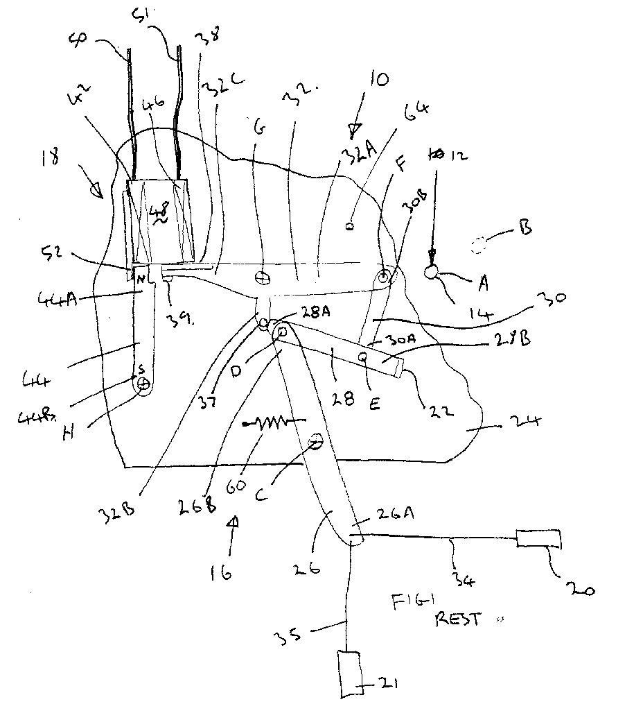
- a latch arrangement 10 having a latch 12 (only part of which is shown), a release mechanism 16, powered control means 18 and manually actuable elements in the form of inside handle 20 and outside handle 21.
- the latch 12 is mounted on a car door and is operable to releasably retain a striker mounted on fixed structure of the car, such as a B post or a C post.
- the latch 12 typically might include a latch bolt in the form of a rotating claw which engages the striker.
- a pawl can be provided to retain the latch bolt in its closed position.
- the pawl includes a latch release element in the form of a pawl pin 14.
- the release mechanism includes release lever 26, release link 28, connector link 30 and lock/unlock lever 32.
- Release lever 26 is pivotally mounted about pivot C on chassis 24 of the latch arrangement.
- One end 26A of release lever 26 is connected via linkage 34 (shown schematically) to a manually actuable element in the form of an inside handle 20.
- End 26A is further connected by a further linkage 35 (shown schematically) to a further manually actuable element in the form of an outside door handle 21.
- End 26B of release lever 26 is connected via pivot D to end 28A of release link 28.
- End 28B of release link 28 includes an abutment 22 for engagement with pawl pin 14 as will be further described below.
- Release link 28 is connected to end 30A of connector 30 by pivot E which is positioned between end 28A and 28B.
- End 30B of connector 30 is connected to end of arm 32A of lock/unlock lever 32 by a pivot F.
- Lock/unlock lever 32 further includes arm 32B having pin 37 and arm 32C having abutment 38 and 39. Lock/unlock lever 32 is pivotally mounted about pivot G onto chassis 24.
- Lock/unlock lever 32 is made from mild steel and hence in particular abutment 38 is made from a ferromagnetic material though in further embodiments this need not be the case (see below).
- Powered control means 18 includes electromagnet 42 and magnetic pawl 44.
- Electromagnetic 42 is mounted on chassis 24 and includes windings 46, core 48 and electric leads 50 and 51.
- Pawl stop 52 is provided on one side of the electromagnet 42.
- Magnetic pawl 44 includes a permanent magnet and is pivotally mounted about pivot H onto chassis 24. End 44A of pawl 44 includes abutment 54, 56 and 58, which will be further described below.
- a tension spring 60 is connected to chassis 24 and release lever 26 and acts to bias release lever 26 in an anticlockwise direction when viewing figure 1.
- a further tension spring 62 biases pin 37 and pivot 38 together.
- springs acting in torsion can be used in particular springs acting in torsion (clock springs) in place of tension springs 60 and 62 to perform the same biasing action.
- a lock/unlock lever stop 64 is mounted on the chassis 24.
- Magnetic pawl 44 has a south pole at end 44B and a north pole at end 44A.
- the centre of gravity of pawl 44 is substantially at pivot H since, in the event of a road traffic accident, such an arrangement will not tend to rotate the pawl as a result of acceleration or deceleration occurring during the accident.
- a relatively light detent is provided to maintain the magnetic pawl 44 in either of the positions as shown in figure 1A and figure 1B which can nevertheless be overcome by manual operation of the key or by pulsing the electromagnet.
- the powered control means 18 has three conditions namely a first condition at which no power is applied to the windings and the magnetic pawl 44 is in the position as shown in figure 1B.
- a third condition at which no power is supplied to the windings 46 and the magnetic pawl 44 is in position as shown in figure 1 and 1A.
- the magnetic pawl is positioned as shown in figure 1 and thus does not restrict rotation of the lock/unlock lever 32 in an anticlockwise direction.
- lock/unlock lever has rotated anticlockwise about pivot G to a position where arm 32A has come into abutment with abutment 64. It should also be noted that abutment 38 has become disengaged from the electromagnet 42.
- lock/unlock lever 32 cannot rotate further in an anticlockwise direction.
- connector 30 is caused to rotate anticlockwise about pivot F relative to lock/unlock lever 32. This results in abutment 22 of release link 28 moving into engagement with pawl pin 14 and moving it from position A as shown in figure 2 to position B as shown in figure 3.
- spring 60 and spring 62 return the release mechanism 16 and pawl pin 14 to the position as shown in figure 1.
- control means With the control means in its second condition i.e. DC current supplied to the windings in the first direction and the magnetic pawl is in a position as shown in figure 1 the lock/unlock lever 32 is maintained in the position as shown in figure 1 by magnetic attraction.
- an abutment such as abutment 22 to be permanently aligned with a latch release element such as pawl pin 42 but remote therefrom such that with the latch arrangement in a locked condition the abutment approaches the pawl pin but does not move it and with the latch arrangement in an unlocked condition the abutment approaches, engages and then moves the pawl pin.
- FIG. 2 shows schematically a power actuator P which is independently operable to release the latch.
- a coded security device 70 in the form of an externally mounted key barrel into which can be inserted a key. Actuation of the key barrel via the key is capable of moving the magnetic pawl between the positions shown in figures 1A and 1B.
- the latch arrangement is configured such that when the associated vehicle is in use the control means is set to its second condition i.e. power is maintained to the windings. Under such circumstances electric power lost to resistance in the windings 46 can be compensated for by the fact that the engine of the vehicle is running and hence the battery recharging system (such as an alternator) can recharge the battery to ensure it does not go flat.
- the battery recharging system such as an alternator
- control means When the vehicle is parked and left unattended the control means can be set to its first condition to lock the latch. Note that the control system does not cause any drain to the vehicle battery in its first condition.
- the control mechanism can also be set to its third condition when the vehicle is parked and is required to be in an unlocked condition. Note that in the third condition there is no drain on the battery.
- the control means can be changed between its first and third condition by applying a pulse of electrical power to the windings in an appropriate direction.
- the lock/unlock lever 32 With the vehicle in use and the control means in its second condition, as mentioned above, the lock/unlock lever 32 is maintained in the position as shown in figure 1 by power been fed to the electromagnet.
- the control means In the event of a power failure, such as might occur following a road traffic accident, the control means will by definition change to its third condition and hence the doors will become unlocked and occupants of the vehicle will be able to escape from the vehicle.
- control means 18 has two ways of preventing rotation of the lock/unlock lever 32, namely by permanently energisation of the windings 46 or by movement of magnetic pawl 44 to the position as shown in figure 1B.
- the control means can be used to simply lock and unlock the vehicle e.g. when parked. As such it is only necessary for the windings 46 to be pulsed to move the magnetic between the positions as shown in figures 1A and figure 1B.
- the electromagnet 42 is not required to attract lock/unlock lever 32 which can therefore be made of a non ferromagnetic material, such as a plastics material.
- the electromagnet 42 need only be strong enough to retain the lock/unlocked lever 32 in the position shown in figure 1 when the electromagnet is in its second condition i.e. when power is being supplied to the electromagnet.
- the electromagnet has to strong enough to overcome the forces in tension spring 60 during initial movement of inside or outside handle and it has to overcome the forces in tension spring 60 and 62 during a subsequent movement of the inside or outside handle.
- the electromagnet is not required to be strong enough to move the lock/unlock lever from the position as shown in figure 2 to a position such that abutment 38 engages with the electromagnet.
- the latch release mechanism 16 can then operate in its two stage manner i.e. alignment of abutment 22 with pawl 14 followed by movement of pawl 14 from position A to position B as shown in figure 1 to open the latch. Under such an arrangement it is preferable that the release mechanism 16 fully returns to the rest position upon release of the inside handle i.e. abutment 22 becomes mis-aligned with pawl pin 14.
- Lock/unlock lever 132 is pivotally mounted about pivot G1 and includes a portion 132A having a hole 132B for connection to further parts of the release mechanism (not shown).
- Lock/unlock lever 132 further includes a cam follower 171. Lock/unlock lever 132 is biased in an anticlockwise direction by spring 172. Lock/unlock lever 132 can be moved between a locked and unlocked condition by a coded security device in the form of a key and key barrel 170 (shown schematically).
- Powered control means 118 includes an axially movable armature 173 which is biased to a central position (as shown in figure 5) by arms 174A and 174B of centring spring 174 acting on pin 173A of armature 173 and also on pin 175 mounted on a chassis of the latch arrangement.
- Armature 173 includes a wasted portion 176 (see figure 5A) having cam surfaces 176A and 176B both in the form of frustoconical surfaces.
- End 177 of the armature is positioned within windings 178 and end 179 of the armature is positioned within windings 180 to provide for a solenoid arrangement.
- end 179 of the armature is positioned within windings 180 to provide for a solenoid arrangement.
- permanent magnets 181 are adjacent the left hand end of windings 180.
- a cam arrangement can be used, such as a desmadromic cam arrangement, in place of spring 172 in order that the lock/unlock lever is returned to the position as shown in figure 5 as the armature is returned to its central position.
- a powered control means 218 in which a lock/unlock lever 232 is pivotally mounted about axis G2 and is connected by pin 285 to armature 286 of solenoid 242.
- a motor 287 moves pawl 244 between an unlocked position (shown chain dotted) and a locked position wherein end 244A of pawl 244 is aligned with armature 286 such that it is prevented from moving downwards as shown in figure 6 from the locked position of lock/unlock lever 232 to the unlocked position (shown chain dotted).
- a key and key barrel 270 can be used to move the pawl 244 between its locked and unlocked positions.
- a latch arrangement 310 having components which fulfil substantially the same function a those in latch arrangement 10 labelled 300 greater.
- a latch bolt in the form of a rotating claw 1 pivotably mounted about pivot W which is retained in the position as shown in figure 7 by pawl 2 which is pivotably mounted about pivot X.
- a striker 3 can be retained in the position as shown in figure 7 to latch a door in a closed position.
- claw 1 includes a cam lug 4 on the outer periphery thereof which engages with lug 5 of lock/unlock lever 332 as will be further described below.
- Figure 7A shows the latch arrangement 310 in an unlocked condition wherein release lever 326 is in abutment with abutment 390, lock/unlock lever 332 is in abutment with abutment 64 and end 328A of release link 328 is in abutment with pin 337 with abutment 338 being remote from electromagnet 342. In this position abutment 332 aligns with pin 314. Note that the position of components shown in figure 7A is equivalent to the position of similar components as shown in figure 2.
- Figure 7B shows the latch arrangement 310 in a locked condition wherein electrical power is fed to windings 346 to maintain abutment 338 in engagement with the electromagnet.
- release lever 326 is still in engagement with abutment 390 whilst lock/unlock lever 332 is no longer in engagement with abutment 64 and end 328A of release link 328 is no longer in engagement with pin 337.
- abutment 332 is now mis-aligned with pawl pin 314.
- pivotal movement of the release lever 326 in a clockwise direction will cause abutment 322 to bypass pin 314 and thus the door will remain closed.
- FIG. 7A shows that in the event that the release lever 326 is pivoted in a clockwise direction so as to disengage abutment 390, the release lever 326, release link 328, and connector 330 will move to the position as shown in figure 7C resulting in abutment 322 engaging and moving pin 314 to position B as shown in figure 7C, thus allowing the door the to open.
- the latch arrangement 310 only momentarily achieves the position as shown in figure 7C since once in this position the claw 1 rotates anticlockwise about pivot W which simultaneously releases the striker 3 from the mouth of the claw and also causes cam lug 4 to contact lug 5 thus driving the lock/unlock lever to the position as shown in figure 7D.
- This allows the pawl pin 314 to return to position A and causes the connector 330 and release link 328 to adopt the position as shown in figure Note that as shown in figure 7D, the release lever is disengaged from abutment 390 i.e. an inside or outside door handle is still in an actuated position.
- the door latch can then be locked either by supplying an maintaining power to windings 346 or by pulsing windings 346 such that pawl 344 moves clockwise to a position equivalent to that shown in figure 1B or by manual operation of the key again moving pawl 344. Subsequent release of the inside or outside door handle will either return the latch arrangement to the position as shown in figure 7B (when power is supplied and maintained to windings 346) or to the position as shown in figure 7B except with the pawl moved across.
- electromagnet 342 is therefore only required to hold the lock/unlocked lever in the locked position as shown in figure 7 and is not required to return it to that position from the unlocked position since this is carried out by co-operation between cam lug 4 and lug 5.
Abstract
Description
- The present invention relates to latch arrangements, and in particular latch arrangements for use within doors of cars (automobiles).
- Known car doors include latches for releasably retaining the car door in a closed position. Such latches can be locked when the car is left unattended or even when an occupant is in the vehicle so as to prevent access to the vehicle by unauthorised people.
- Such latches can be moved between a locked and unlocked condition either by manual means such as by operating an inside sill button or an exterior key barrel, or they can be powered between the locked and unlocked conditions by a power actuator, which can be controlled remotely by, for example, infra red devices.
- A problem with such power locking/unlocking is that in the event that power is lost e.g. during a road traffic accident or as a result of a flat battery, it may not be possible to change the state of the lock. Thus where a vehicle is in use and the doors are locked and the vehicle is involved in a road traffic accident, the occupant of the vehicle may find themselves locked in the vehicle immediately following the crash and this clearly has safety implications.
- Furthermore the power actuator is expensive to produce and manufacture.
- An object of the present invention is to provide an improved form of latch arrangement.
- Thus according to the present invention there is provided a latch arrangement including a latch, a manually actuable element, a release mechanism and a power control means, the latch being operable to releasably retain a striker in use, the release mechanism being capable of being moved by the manually actuable element from a latched position to an unlatched position wherein it unlatches the latch, the power control means having a first, second and third condition in which:-
- with the power control means in the first condition the control means is in a non powered condition and actuation of the manually actuable element does not cause the release mechanism to unlatch the latch,
- with the power control means in the second condition the powered control means is in a powered condition and actuation of the manually actuable element does not cause the release mechanism to unlatch the latch,
- and with the power control means in the third condition the power control means is in a non powered condition and actuation of the manually actuable element causes the release mechanism to unlatch the latch.
-
- The invention will now be described, by way of example only, with reference to the accompanying drawings in which:-
- FIGURE 1 is a view of a latch arrangement according to the present invention;
- FIGURE 1A is an enlarged view of part of the figure 1
- FIGURE 1B is a view similar to figure 1A with the magnetic pawl in a different position;
- FIGURE 2 shows the latch arrangement of figure 1 part way through an opening operation in an unlocked but latched condition;
- FIGURE 3 shows the latch arrangement of figure 1 at the end of an opening operation in an unlatched condition; and
- FIGURE 4 shows the latch arrangement of figure 1 wherein an attempt has been made to open the latch whilst in a locked condition.
- FIGURES 5 and 5A shows a further embodiment of a latch arrangement according to the present invention;
- FIGURE 6 shows a further embodiment of a latch arrangement according to the present invention; and
- FIGURES 7 to 7D shows a further embodiment of a latch arrangement according to the present invention.
-
- With reference to the figures 1 to 4 there is shown a
latch arrangement 10 having a latch 12 (only part of which is shown), arelease mechanism 16, powered control means 18 and manually actuable elements in the form ofinside handle 20 andoutside handle 21. - The latch 12 is mounted on a car door and is operable to releasably retain a striker mounted on fixed structure of the car, such as a B post or a C post. The latch 12 typically might include a latch bolt in the form of a rotating claw which engages the striker. To ensure the claw retains the striker, a pawl can be provided to retain the latch bolt in its closed position. The pawl includes a latch release element in the form of a
pawl pin 14. - With the
pawl pin 14 in position A as shown in figure 1, closing of the door will cause the rotating claw to engage the striker and the pawl will then retain the striker in the closed position. Movement of thepawl pin 14 to the position B as shown in figure 1 will release the pawl from engagement with the claw thus allowing the striker to be released from the claw and allowing the door to open. Thus with the pawl pin in the position A of figure 1 the latch can be latched to the striker and with the pawl pin in the position B of figure 1 the latch can be unlatched from the striker. - The release mechanism includes
release lever 26, releaselink 28,connector link 30 and lock/unlock lever 32. -
Release lever 26 is pivotally mounted about pivot C onchassis 24 of the latch arrangement. Oneend 26A ofrelease lever 26 is connected via linkage 34 (shown schematically) to a manually actuable element in the form of aninside handle 20. -
End 26A is further connected by a further linkage 35 (shown schematically) to a further manually actuable element in the form of anoutside door handle 21. - Operation of either handle 20 or 21 causes the release lever to rotate clockwise about pivot C.
- End 26B of
release lever 26 is connected via pivot D to end 28A ofrelease link 28. - End 28B of
release link 28 includes anabutment 22 for engagement withpawl pin 14 as will be further described below. -
Release link 28 is connected to end 30A ofconnector 30 by pivot E which is positioned betweenend 28A and 28B. End 30B ofconnector 30 is connected to end ofarm 32A of lock/unlock lever 32 by a pivot F. - Lock/
unlock lever 32 further includesarm 32B having pin 37 andarm 32C having abutment unlock lever 32 is pivotally mounted about pivot G ontochassis 24. - Lock/
unlock lever 32 is made from mild steel and hence inparticular abutment 38 is made from a ferromagnetic material though in further embodiments this need not be the case (see below). - Powered control means 18 includes electromagnet 42 and
magnetic pawl 44. - Electromagnetic 42 is mounted on
chassis 24 and includes windings 46,core 48 and electric leads 50 and 51. Pawlstop 52 is provided on one side of the electromagnet 42. -
Magnetic pawl 44 includes a permanent magnet and is pivotally mounted about pivot H ontochassis 24.End 44A ofpawl 44 includesabutment - A tension spring 60 is connected to
chassis 24 andrelease lever 26 and acts tobias release lever 26 in an anticlockwise direction when viewing figure 1. - A further tension spring 62 (only shown in figure 3 for clarity)
biases pin 37 andpivot 38 together. - In further embodiments different forms of springs can be used in particular springs acting in torsion (clock springs) in place of tension springs 60 and 62 to perform the same biasing action.
- A lock/
unlock lever stop 64 is mounted on thechassis 24. - As a result of tension spring 62
end 28A ofrelease link 28 is biased into engagement withpin 37. In further embodiments the end ofrelease lever 26 could engagepin 37 as could a part of pivot D. -
Magnetic pawl 44 has a south pole at end 44B and a north pole atend 44A. - Applying DC current to the windings 46 via electric leads 50 and 51 in a first direction will create a magnetic field around the electromagnet which will bias the north pole in
end 44A ofmagnetic pawl 44 to the left when viewing figure 1 i.e. anticlockwise about pivot H until abutment 54 engagespawl stop 52. - Applying DC current in a second direction to windings 46 via electric 50 and 51 will cause a different magnetic field to form around the electromagnet such that
north pole end 44A ofmagnetic pawl 44 is biased to the right when viewing figure 1 i.e. clockwise around pivot H until such time asabutment 56 engagesend 33 ofarm 32C of lock/unlock lever 32 (see figure 1B). Under theseconditions abutment 58 isopposite abutment 39 and will prevent rotation of lock/unlock lever 32 anticlockwise about pivot G (see below). - Note that to move the magnetic pawl between the positions as shown in figures 1A and 1B it is only necessary to apply a short pulse (e.g. 50 ms) of current to windings 46 in the appropriate direction since under normal circumstances once the
magnetic pawl 44 has achieved one of the positions as shown in figures 1A or 1B there are no forces which tend to move it out of that positions. - Note that in a preferred embodiment the centre of gravity of
pawl 44 is substantially at pivot H since, in the event of a road traffic accident, such an arrangement will not tend to rotate the pawl as a result of acceleration or deceleration occurring during the accident. - Note that in a further preferred embodiment a relatively light detent is provided to maintain the
magnetic pawl 44 in either of the positions as shown in figure 1A and figure 1B which can nevertheless be overcome by manual operation of the key or by pulsing the electromagnet. - It is also possible to prevent rotation of lock/
unlock lever 32 anticlockwise about pivot G by applying and maintaining DC current in the first direction to windings 46 sinceabutment 38 is made from a ferromagnetic material and will therefore be magnetically attracted to electromagnet 42. - The powered control means 18 has three conditions namely a first condition at which no power is applied to the windings and the
magnetic pawl 44 is in the position as shown in figure 1B. - A second condition at which power is supplied and maintained in a first direction to windings 46 thus attracting
abutment 38 and ensuring that themagnetic pawl 44 is positioned as shown in figure 1 and 1A. - A third condition at which no power is supplied to the windings 46 and the
magnetic pawl 44 is in position as shown in figure 1 and 1A. - It is important to note that in this case the physical position of various components when in the second and third conditions is the same. Thus the second and third conditions differ only in that in the second condition power is supplied to windings 46 and in the third condition no power is supplied.
- Operation of the latch arrangement is as follows.
- With the control means 18 in the third condition the door can be manually opened as follows.
- As mentioned previously with the control means in the third condition the magnetic pawl is positioned as shown in figure 1 and thus does not restrict rotation of the lock/
unlock lever 32 in an anticlockwise direction. - Furthermore no power is supplied to the windings 46 and thus the electromagnet also does not restrict movement of the lock/
unlock lever 32 in an anticlockwise direction. - Initial movement of either the
inside handle 20 or outside handle 21 moves therelease lever 26 in a clockwise direction about pivot C to the unlocked position as shown in figure 2. - It should be noted that lock/unlock lever has rotated anticlockwise about pivot G to a position where
arm 32A has come into abutment withabutment 64. It should also be noted thatabutment 38 has become disengaged from the electromagnet 42. - It can also be seen from figure 2 that
end 28A ofrelease link 28 has remained in contact withpin 37. Thusconnector 30 andrelease link 28 have also substantially rotated about pivot G. Note that as shown in figure 2abutment 22 had become aligned withpawl pin 14. This can be contrasted with the position ofabutment 22 as shown in figure 1 where it is not aligned withpawl pin 14. - Further movement of the inside or outside door handle moves the
release lever 26 from the position as shown in figure 2 to the position as shown in figure 3. - In view of the fact that
arm 32A of lock/unlock lever 32 is in abutting engagement withabutment 64, lock/unlocklever 32 cannot rotate further in an anticlockwise direction. Thusconnector 30 is caused to rotate anticlockwise about pivot F relative to lock/unlock lever 32. This results inabutment 22 ofrelease link 28 moving into engagement withpawl pin 14 and moving it from position A as shown in figure 2 to position B as shown in figure 3. - As previously mentioned movement of the pawl pin from position A to position B causes the latch to unlock.
- When the inside and outside handles are released, spring 60 and spring 62 return the
release mechanism 16 andpawl pin 14 to the position as shown in figure 1. - Note that whilst the movement of the inside or outside handle and hence movement of the
release lever 26 has been described in two stages, such two stage movement is not discernible by a person operating the door handles. Furthermore the mechanism is designed to move seamlessly from the position as shown in figure 3 to the position as shown in figure 1. - With the control means in its second condition i.e. DC current supplied to the windings in the first direction and the magnetic pawl is in a position as shown in figure 1 the lock/
unlock lever 32 is maintained in the position as shown in figure 1 by magnetic attraction. - Thus operation of an inside or outside door handle will cause the
release lever 26 to rotate in a clockwise direction as shown in figure 1 which will result inend 28A ofrelease link 28 immediately disengagingpin 37 such that therelease lever 26,release link 28 andconnector 30 moves to the position as shown in figure 4. - It should be noted that whilst
abutment 22 has being caused to move, in view of the fact that it was initially mis-aligned withpawl pin 14, such movement has resulted inabutment 22 bypassingpawl pin 14 and not imparting any movement topawl pin 14. Thus whilst the inside or outside handle has been moved, the door has not become unlatched. Note that in further embodiments it is possible to arrange an abutment such asabutment 22 to be permanently aligned with a latch release element such as pawl pin 42 but remote therefrom such that with the latch arrangement in a locked condition the abutment approaches the pawl pin but does not move it and with the latch arrangement in an unlocked condition the abutment approaches, engages and then moves the pawl pin. - It can be seen that with the control means in its second condition, the door latch remains in a locked condition.
- With the control means in the first condition i.e. where there is no power to the windings 46 but the
magnetic pawl 44 is in a position as shown in figure 1B, anticlockwise rotation of the lock/unlock lever is again prevented though this time by co-operation ofabutments release lever 26,release link 28 andconnector 30 to move to the position as shown in figure 4. - Consideration of figure 2 shows schematically a power actuator P which is independently operable to release the latch.
- Further shown schematically is a
coded security device 70 in the form of an externally mounted key barrel into which can be inserted a key. Actuation of the key barrel via the key is capable of moving the magnetic pawl between the positions shown in figures 1A and 1B. - The latch arrangement is configured such that when the associated vehicle is in use the control means is set to its second condition i.e. power is maintained to the windings. Under such circumstances electric power lost to resistance in the windings 46 can be compensated for by the fact that the engine of the vehicle is running and hence the battery recharging system (such as an alternator) can recharge the battery to ensure it does not go flat.
- When the vehicle is parked and left unattended the control means can be set to its first condition to lock the latch. Note that the control system does not cause any drain to the vehicle battery in its first condition.
- The control mechanism can also be set to its third condition when the vehicle is parked and is required to be in an unlocked condition. Note that in the third condition there is no drain on the battery.
- The control means can be changed between its first and third condition by applying a pulse of electrical power to the windings in an appropriate direction.
- With the vehicle in use and the control means in its second condition, as mentioned above, the lock/
unlock lever 32 is maintained in the position as shown in figure 1 by power been fed to the electromagnet. In the event of a power failure, such as might occur following a road traffic accident, the control means will by definition change to its third condition and hence the doors will become unlocked and occupants of the vehicle will be able to escape from the vehicle. - With the vehicle parked and with the control means in its first condition i.e. with the vehicle locked, in the event that the vehicle battery is flattened, perhaps as a result of a interior light being left on, pulsing of the electromagnet to move the control means from the first and third condition to unlock the vehicle will not be possible. However, it is nevertheless possible to manually unlock the vehicle by use of the key and
key barrel 70. The key and key barrel can also be used to lock the vehicle if necessary. - It should be noted that only when the vehicle is in use is power continually fed to windings 46. When the vehicle is parked power is only momentarily fed to windings 46 to change between the locked and unlocked condition.
- As mentioned above the control means 18 has two ways of preventing rotation of the lock/
unlock lever 32, namely by permanently energisation of the windings 46 or by movement ofmagnetic pawl 44 to the position as shown in figure 1B. In further embodiments, in particular when no power release P is provided, the control means can be used to simply lock and unlock the vehicle e.g. when parked. As such it is only necessary for the windings 46 to be pulsed to move the magnetic between the positions as shown in figures 1A and figure 1B. As such the electromagnet 42 is not required to attract lock/unlock lever 32 which can therefore be made of a non ferromagnetic material, such as a plastics material. Under these circumstances it is necessary to have a manual override system operable by the inside h Such an arrangement therefore significantly reduces the likelihood of flattening the battery when the vehicle is parked but the nevertheless allows opening of the doors in the event of power loss following a road traffic accident. - It should be noted that the electromagnet 42 need only be strong enough to retain the lock/
unlocked lever 32 in the position shown in figure 1 when the electromagnet is in its second condition i.e. when power is being supplied to the electromagnet. Thus the electromagnet has to strong enough to overcome the forces in tension spring 60 during initial movement of inside or outside handle and it has to overcome the forces in tension spring 60 and 62 during a subsequent movement of the inside or outside handle. Note that the electromagnet is not required to be strong enough to move the lock/unlock lever from the position as shown in figure 2 to a position such thatabutment 38 engages with the electromagnet.
andle (but not the outside handle) such that when the inside handle is moved themagnetic pawl 44, if in the position as shown in figure 1B, is moved to the position as shown in figure 1A. Once the magnetic pawl is in the position as shown in figure 1A, thelatch release mechanism 16 can then operate in its two stage manner i.e. alignment ofabutment 22 withpawl 14 followed by movement ofpawl 14 from position A to position B as shown in figure 1 to open the latch. Under such an arrangement it is preferable that therelease mechanism 16 fully returns to the rest position upon release of the inside handle i.e.abutment 22 becomes mis-aligned withpawl pin 14. - With reference to figure 5 there is shown various components of a
further latch arrangement 110. - Lock/
unlock lever 132 is pivotally mounted about pivot G1 and includes aportion 132A having a hole 132B for connection to further parts of the release mechanism (not shown). - Lock/
unlock lever 132 further includes a cam follower 171. Lock/unlock lever 132 is biased in an anticlockwise direction byspring 172. Lock/unlock lever 132 can be moved between a locked and unlocked condition by a coded security device in the form of a key and key barrel 170 (shown schematically). - Powered control means 118 includes an axially
movable armature 173 which is biased to a central position (as shown in figure 5) byarms 174A and 174B ofcentring spring 174 acting onpin 173A ofarmature 173 and also onpin 175 mounted on a chassis of the latch arrangement.Armature 173 includes a wasted portion 176 (see figure 5A) havingcam surfaces - End 177 of the armature is positioned within
windings 178 and end 179 of the armature is positioned withinwindings 180 to provide for a solenoid arrangement. In particular adjacent the left hand end ofwindings 180 are permanent magnets 181. - Operation of the
latch arrangement 110 is as follows. - When the vehicle upon which
latch arrangement 110 is mounted is in use and is required to be in a locked condition, power is supplied and maintained towindings 178 in such a manner that the armature moves to the left as shown in figure 5 resulting in cam follower 171 being biased radially outwards relative to the axis of the armature bysurface 176B such that lock/unlock lever 132 is rotated clockwise to a locked position. In the event of a road traffic accident, where the power to thewindings 178 is cut, thecentring spring 174 returns the armature to the position as shown in figure 5 andspring 172 therefore returns the lock/unlock lever 132 to the position as shown in figure 5 thus unlocking the door and allowing access to egress to or from the vehicle. - In the event that the vehicle is to be left in a parked and locked condition, a pulse of power is provided to the
windings 180 in such a manner that the armature moves to the right as shown in figure 5. However, under these circumstances, because of a flux loop created by the winding housing 180A in conjunction with magnets 181 and the right hand portion ofarmature 173, thearmature 173 remains in the right hand position even when no current flows inwindings 180. - Thus it can be seen that it is possible to lock the vehicle when parked and no power is being drained from the vehicle battery whilst parked and locked.
- In the event that the vehicle is to be unlocked, a pulse of power is supplied to
windings 180 such that the armature moves to the left and achieves the position as shown in figure 5. - In further embodiments, a cam arrangement can be used, such as a desmadromic cam arrangement, in place of
spring 172 in order that the lock/unlock lever is returned to the position as shown in figure 5 as the armature is returned to its central position. - With reference to figure 6 there is a shown a further embodiment of a powered control means 218 in which a lock/unlock lever 232 is pivotally mounted about axis G2 and is connected by
pin 285 to armature 286 of solenoid 242. Amotor 287 moves pawl 244 between an unlocked position (shown chain dotted) and a locked position whereinend 244A of pawl 244 is aligned witharmature 286 such that it is prevented from moving downwards as shown in figure 6 from the locked position of lock/unlock lever 232 to the unlocked position (shown chain dotted). - A key and
key barrel 270 can be used to move the pawl 244 between its locked and unlocked positions. - Note that in this case the solenoid 242 is required to move the lock/unlock lever from the unlocked position to the locked position.
- With reference to figures 7 to 7D there is shown a further embodiment of a
latch arrangement 310 having components which fulfil substantially the same function a those inlatch arrangement 10 labelled 300 greater. Further shown is a latch bolt in the form of a rotating claw 1 pivotably mounted about pivot W which is retained in the position as shown in figure 7 bypawl 2 which is pivotably mounted about pivot X. A striker 3 can be retained in the position as shown in figure 7 to latch a door in a closed position. In this case claw 1 includes acam lug 4 on the outer periphery thereof which engages withlug 5 of lock/unlock lever 332 as will be further described below. - In this case there is further included an
abutment 390 which limits anticlockwise rotation ofrelease lever 26. - Figure 7A shows the
latch arrangement 310 in an unlocked condition whereinrelease lever 326 is in abutment withabutment 390, lock/unlock lever 332 is in abutment withabutment 64 andend 328A ofrelease link 328 is in abutment withpin 337 withabutment 338 being remote fromelectromagnet 342. In thisposition abutment 332 aligns withpin 314. Note that the position of components shown in figure 7A is equivalent to the position of similar components as shown in figure 2. - Figure 7B shows the
latch arrangement 310 in a locked condition wherein electrical power is fed towindings 346 to maintainabutment 338 in engagement with the electromagnet. Note thatrelease lever 326 is still in engagement withabutment 390 whilst lock/unlock lever 332 is no longer in engagement withabutment 64 andend 328A ofrelease link 328 is no longer in engagement withpin 337. Note also thatabutment 332 is now mis-aligned withpawl pin 314. Thus pivotal movement of therelease lever 326 in a clockwise direction will causeabutment 322 to bypasspin 314 and thus the door will remain closed. - Consideration of figure 7A shows that in the event that the
release lever 326 is pivoted in a clockwise direction so as to disengageabutment 390, therelease lever 326,release link 328, andconnector 330 will move to the position as shown in figure 7C resulting inabutment 322 engaging and movingpin 314 to position B as shown in figure 7C, thus allowing the door the to open. - It should be noted that the
latch arrangement 310 only momentarily achieves the position as shown in figure 7C since once in this position the claw 1 rotates anticlockwise about pivot W which simultaneously releases the striker 3 from the mouth of the claw and also causescam lug 4 to contactlug 5 thus driving the lock/unlock lever to the position as shown in figure 7D. This in turn allows thepawl pin 314 to return to position A and causes theconnector 330 and release link 328 to adopt the position as shown in figure
Note that as shown in figure 7D, the release lever is disengaged fromabutment 390 i.e. an inside or outside door handle is still in an actuated position. - With the inside or outside handle in its actuated position, the door latch can then be locked either by supplying an maintaining power to
windings 346 or by pulsingwindings 346 such thatpawl 344 moves clockwise to a position equivalent to that shown in figure 1B or by manual operation of the key again movingpawl 344. Subsequent release of the inside or outside door handle will either return the latch arrangement to the position as shown in figure 7B (when power is supplied and maintained to windings 346) or to the position as shown in figure 7B except with the pawl moved across. - Alternatively where no power is supplied to
windings 346 then neither the electromagnet orpawl 344 will restrict rotational movement of the lock/unlock lever 332 which, upon release of the inside or outside door handle will return to the position as shown in figure 7C. - It can be seen that
electromagnet 342 is therefore only required to hold the lock/unlocked lever in the locked position as shown in figure 7 and is not required to return it to that position from the unlocked position since this is carried out by co-operation betweencam lug 4 andlug 5. - In an alternative embodiment it is possible to provide an electromagnet which is sufficiently powerful to move the lock/unlock lever from the position as shown in figure 7A to the position as shown in figure 7B so as to be able to lock the door without having to open the door.
Claims (19)
- A latch arrangement including a latch, a manually actuable element, a release mechanism and a power control means, the latch being operable to releasably retain a striker in use, the release mechanism being capable of being moved by the manually actuable element from a latched position to an unlatched position wherein it unlatches the latch, the power control means having a first, second and third condition in which:-with the power control means in the first condition the control means is in a non powered condition and actuation of the manually actuable element does not cause the release mechanism to unlatch the latch,with the power control means in the second condition the powered control means is in a powered condition and actuation of the manually actuable element does not cause the release mechanism to unlatch the latch,and with the power control means in the third condition the power control means is in a non powered condition and actuation of the manually actuable element causes the release mechanism to unlatch the latch.
- A latch arrangement as defined in claim 1 in which a part of the release mechanism is retained in a locked position by the control means to provide for a lock condition of the latch.
- A latch arrangement as defined in claim 2 in which said part of the release mechanism is retained by magnetic attraction.
- A latch arrangement as defined in claim 2 or 3 in which said part of the release mechanism is retained by a pawl.
- A latch arrangement as defined in claims 2 to 4 in which said part of the release mechanism is a lock/unlock lever which is retained in the first position by the control means to provide for the lock condition and is allowed to move to a second position to provide for the unlocked condition.
- A latch arrangement as defined in claims 2 to 5 in which the control means includes a electromagnet to retain said part of the release mechanism in the unlocked position.
- A latch arrangement as defined in claim 6 in which the electromagnet is incapable of moving the said part of the release mechanism from the unlocked to the locked position.
- A latch arrangement as defined in any preceding claim in which the control means includes a magnetic pawl movable between a locked and unlocked position.
- A latch arrangement as defined in claim 8 in which the electromagnet is pulsed to move the pawl between the locked and unlocked position.
- A latch arrangement as defined in claim 8 or 9 in which the pawl is pivotally movable and the centre of gravity of the pawl is substantially at the axis of the pivot.
- A latch arrangement as defined in any preceding claim in which the release mechanism is designed to return to the rest position from the release position upon release of the manually actuable element.
- A latch arrangement as defined in claim 11 in which the release mechanism is biased to the rest position by resilient means.
- A latch arrangement as defined in claim 12 in which a first resilient means biases the release mechanism to the unlocked position from the released position and a second resilient means biases the release mechanism to the rest position from the unlock position.
- A latch arrangement as defined in any preceding claim in which unlatching of the latch arrangement causes the release mechanism to move to a locked condition
- A latch arrangement as defined in claim 13 in which the release mechanism can be retained in the locked condition whilst the latch is in its unlatched condition.
- A latch arrangement as defined in claim 14 in which the release mechanism is retained in the locked condition by putting the control means into the first condition
- A latch arrangement as defined in claim 14 in which the release mechanism is retained in the locked condition by putting the control means into the second condition.
- A latch arrangement as defined in any preceding claim in which the latch is further movable between a latched and released position by a powered released actuator.
- A latch arrangement as defined in any preceding claim in which the control means is movable between the locked and unlocked conditions by manual operation of a coded security device such as a key.
Applications Claiming Priority (2)
| Application Number | Priority Date | Filing Date | Title |
|---|---|---|---|
| GB0031060 | 2000-12-20 | ||
| GBGB0031060.7A GB0031060D0 (en) | 2000-12-20 | 2000-12-20 | Latch arrangement |
Publications (2)
| Publication Number | Publication Date |
|---|---|
| EP1217153A1 true EP1217153A1 (en) | 2002-06-26 |
| EP1217153B1 EP1217153B1 (en) | 2005-02-02 |
Family
ID=9905459
Family Applications (1)
| Application Number | Title | Priority Date | Filing Date |
|---|---|---|---|
| EP01310124A Expired - Lifetime EP1217153B1 (en) | 2000-12-20 | 2001-12-04 | Latch arrangement |
Country Status (4)
| Country | Link |
|---|---|
| US (1) | US6824176B2 (en) |
| EP (1) | EP1217153B1 (en) |
| DE (1) | DE60108714T2 (en) |
| GB (1) | GB0031060D0 (en) |
Cited By (6)
| Publication number | Priority date | Publication date | Assignee | Title |
|---|---|---|---|---|
| EP1783307A1 (en) * | 2005-11-07 | 2007-05-09 | ArvinMeritor Light Vehicle Systems (UK) Ltd | Latch arrangement |
| GB2453514A (en) * | 2007-06-08 | 2009-04-15 | Meritor Technology Inc | Latch with lock link and first and second control members |
| EP2093357A1 (en) | 2008-02-21 | 2009-08-26 | Meritor Technology, Inc. | Vehicle door latch |
| WO2023046246A1 (en) * | 2021-09-24 | 2023-03-30 | Kiekert Aktiengesellschaft | Closing device for a motor vehicle |
| WO2023116959A1 (en) * | 2021-12-21 | 2023-06-29 | Kiekert Aktiengesellschaft | Motor vehicle lock, in particular motor vehicle door lock |
| WO2024002408A1 (en) * | 2022-07-01 | 2024-01-04 | Kiekert Aktiengesellschaft | Motor vehicle lock, in particular motor vehicle door lock |
Families Citing this family (4)
| Publication number | Priority date | Publication date | Assignee | Title |
|---|---|---|---|---|
| US7287785B2 (en) * | 2004-04-02 | 2007-10-30 | Intier Automotive Closures Inc. | Side door latch pawl function augmentation |
| US7261338B2 (en) * | 2004-08-09 | 2007-08-28 | Meritor Technology Inc. | Single actuator power close latch mechanism with failsafe |
| GB0522668D0 (en) * | 2005-11-07 | 2005-12-14 | Arvinmeritor Light Vehicle Sys | Latch arrangement |
| US7956753B2 (en) * | 2008-05-06 | 2011-06-07 | Fogg Filler Company | Tether apparatus |
Citations (4)
| Publication number | Priority date | Publication date | Assignee | Title |
|---|---|---|---|---|
| DE1816942A1 (en) * | 1968-12-24 | 1970-07-02 | Heinz Ott | Device for the automatic unlocking of vehicle doors |
| US4802350A (en) * | 1987-04-29 | 1989-02-07 | Rockwell-Cim | Assembly of a door latch and anti-theft and anti-attack deactivating device for said latch, and latch which is part of said assembly |
| US5894906A (en) * | 1996-11-08 | 1999-04-20 | Weber; Harold J. | Accident responsive safety release for a motor vehicle's rear door child-lock device |
| US6157090A (en) * | 1999-08-18 | 2000-12-05 | Daimlerchrysler Corporation | Electronic child safety locks |
Family Cites Families (17)
| Publication number | Priority date | Publication date | Assignee | Title |
|---|---|---|---|---|
| US1309645A (en) * | 1919-07-15 | lopez | ||
| US709607A (en) * | 1897-03-16 | 1902-09-23 | Henry Joseph Podlesak | Electrical releaser for fire-doors, &c. |
| US971423A (en) * | 1910-05-06 | 1910-09-27 | Frank Walters | Lock. |
| US1057608A (en) * | 1910-08-29 | 1913-04-01 | Nat Clock & Electric Mfg Co | Automatic electric release for fire-doors. |
| US1238345A (en) * | 1916-10-04 | 1917-08-28 | Frank A Schoenle | Magnetic latch device. |
| US1949850A (en) * | 1933-06-22 | 1934-03-06 | Willard Charles | Automobile hood lock |
| US2081055A (en) * | 1936-02-20 | 1937-05-18 | Kiracofe Clifford | Tank cap lock |
| US2219132A (en) * | 1939-01-25 | 1940-10-22 | Anna F Hohmann | Electric door lock |
| US2369362A (en) * | 1942-06-05 | 1945-02-13 | Frank Evans Bowker | Pressure applicator |
| FR2268141B1 (en) * | 1974-04-18 | 1976-12-17 | Alkan R & Cie | |
| FR2542793B1 (en) * | 1983-03-14 | 1985-07-19 | Mecanismes Comp Ind De | LOCK WITH ELECTRIC OPENING, PARTICULARLY FOR MOTOR VEHICLE DOORS |
| GB8622120D0 (en) | 1986-09-13 | 1986-10-22 | Chubb & Sons Lock & Safe Co | Locking mechanisms |
| GB2307506B (en) * | 1995-11-24 | 1999-12-15 | Rockwell Lvs | Vehicle door lock actuator |
| JP3622337B2 (en) * | 1996-04-26 | 2005-02-23 | アイシン精機株式会社 | Door closer equipment |
| DE19635414C2 (en) | 1996-08-31 | 2001-07-12 | Mannesmann Vdo Ag | Lock, especially for vehicle doors or the like |
| JP3301738B2 (en) | 1999-04-21 | 2002-07-15 | 三井金属鉱業株式会社 | Vehicle door latch device with double action mechanism |
| JP3400747B2 (en) | 1999-06-03 | 2003-04-28 | 三井金属鉱業株式会社 | Vehicle door latch device with block type anti-theft mechanism |
-
2000
- 2000-12-20 GB GBGB0031060.7A patent/GB0031060D0/en not_active Ceased
-
2001
- 2001-12-04 DE DE60108714T patent/DE60108714T2/en not_active Expired - Lifetime
- 2001-12-04 EP EP01310124A patent/EP1217153B1/en not_active Expired - Lifetime
- 2001-12-20 US US10/022,674 patent/US6824176B2/en not_active Expired - Fee Related
Patent Citations (4)
| Publication number | Priority date | Publication date | Assignee | Title |
|---|---|---|---|---|
| DE1816942A1 (en) * | 1968-12-24 | 1970-07-02 | Heinz Ott | Device for the automatic unlocking of vehicle doors |
| US4802350A (en) * | 1987-04-29 | 1989-02-07 | Rockwell-Cim | Assembly of a door latch and anti-theft and anti-attack deactivating device for said latch, and latch which is part of said assembly |
| US5894906A (en) * | 1996-11-08 | 1999-04-20 | Weber; Harold J. | Accident responsive safety release for a motor vehicle's rear door child-lock device |
| US6157090A (en) * | 1999-08-18 | 2000-12-05 | Daimlerchrysler Corporation | Electronic child safety locks |
Cited By (7)
| Publication number | Priority date | Publication date | Assignee | Title |
|---|---|---|---|---|
| EP1783307A1 (en) * | 2005-11-07 | 2007-05-09 | ArvinMeritor Light Vehicle Systems (UK) Ltd | Latch arrangement |
| GB2453514A (en) * | 2007-06-08 | 2009-04-15 | Meritor Technology Inc | Latch with lock link and first and second control members |
| US8454061B2 (en) | 2007-06-08 | 2013-06-04 | Inteva Products USA, LLC | Latch system |
| EP2093357A1 (en) | 2008-02-21 | 2009-08-26 | Meritor Technology, Inc. | Vehicle door latch |
| WO2023046246A1 (en) * | 2021-09-24 | 2023-03-30 | Kiekert Aktiengesellschaft | Closing device for a motor vehicle |
| WO2023116959A1 (en) * | 2021-12-21 | 2023-06-29 | Kiekert Aktiengesellschaft | Motor vehicle lock, in particular motor vehicle door lock |
| WO2024002408A1 (en) * | 2022-07-01 | 2024-01-04 | Kiekert Aktiengesellschaft | Motor vehicle lock, in particular motor vehicle door lock |
Also Published As
| Publication number | Publication date |
|---|---|
| GB0031060D0 (en) | 2001-01-31 |
| US20020084657A1 (en) | 2002-07-04 |
| EP1217153B1 (en) | 2005-02-02 |
| DE60108714D1 (en) | 2005-03-10 |
| US6824176B2 (en) | 2004-11-30 |
| DE60108714T2 (en) | 2006-05-04 |
Similar Documents
| Publication | Publication Date | Title |
|---|---|---|
| US20060238283A1 (en) | Latch arrangement | |
| US7532098B2 (en) | Actuator | |
| US8454061B2 (en) | Latch system | |
| EP1790800A2 (en) | Latch Arrangement | |
| US10683682B2 (en) | Closure latch for vehicle door having double pull release mechanism driven by child lock actuator | |
| US6705140B1 (en) | Latch apparatus and method | |
| US5975596A (en) | Vehicle door latch | |
| CA2039072C (en) | Low effort remote latch actuator | |
| US6099048A (en) | Automotive door latching system | |
| US7543861B2 (en) | Lock for an opening on a motor vehicle, with a memory for unlocking locking | |
| EP1217153B1 (en) | Latch arrangement | |
| US4971370A (en) | Self-releasing deck lid latch | |
| EP1783307B1 (en) | Latch arrangement | |
| US5971449A (en) | Vehicle door latch | |
| US6652009B2 (en) | Actuator | |
| CA2382487C (en) | A powered vehicle door latch and actuator therefor | |
| US20230220705A1 (en) | Closure latch assembly with release cable arrangement having an anti-rattle mechanism | |
| JPS631434B2 (en) | ||
| JP2864339B2 (en) | Door lock device for automobile | |
| GB2475272A (en) | A latch having a movable abutment member determining locking and unlatching |
Legal Events
| Date | Code | Title | Description |
|---|---|---|---|
| PUAI | Public reference made under article 153(3) epc to a published international application that has entered the european phase |
Free format text: ORIGINAL CODE: 0009012 |
|
| AK | Designated contracting states |
Kind code of ref document: A1 Designated state(s): AT BE CH CY DE DK ES FI FR GB GR IE IT LI LU MC NL PT SE TR |
|
| AX | Request for extension of the european patent |
Free format text: AL;LT;LV;MK;RO;SI |
|
| RAP1 | Party data changed (applicant data changed or rights of an application transferred) |
Owner name: ARVINMERITOR LIGHT VEHICLE SYSTEMS (UK) LTD |
|
| 17P | Request for examination filed |
Effective date: 20021129 |
|
| AKX | Designation fees paid |
Designated state(s): DE FR GB |
|
| 17Q | First examination report despatched |
Effective date: 20031218 |
|
| GRAP | Despatch of communication of intention to grant a patent |
Free format text: ORIGINAL CODE: EPIDOSNIGR1 |
|
| GRAS | Grant fee paid |
Free format text: ORIGINAL CODE: EPIDOSNIGR3 |
|
| GRAA | (expected) grant |
Free format text: ORIGINAL CODE: 0009210 |
|
| AK | Designated contracting states |
Kind code of ref document: B1 Designated state(s): DE FR GB |
|
| REG | Reference to a national code |
Ref country code: GB Ref legal event code: FG4D |
|
| REG | Reference to a national code |
Ref country code: IE Ref legal event code: FG4D |
|
| REF | Corresponds to: |
Ref document number: 60108714 Country of ref document: DE Date of ref document: 20050310 Kind code of ref document: P |
|
| ET | Fr: translation filed | ||
| PLBE | No opposition filed within time limit |
Free format text: ORIGINAL CODE: 0009261 |
|
| STAA | Information on the status of an ep patent application or granted ep patent |
Free format text: STATUS: NO OPPOSITION FILED WITHIN TIME LIMIT |
|
| 26N | No opposition filed |
Effective date: 20051103 |
|
| REG | Reference to a national code |
Ref country code: FR Ref legal event code: TP |
|
| REG | Reference to a national code |
Ref country code: GB Ref legal event code: 732E |
|
| REG | Reference to a national code |
Ref country code: GB Ref legal event code: 732E Free format text: REGISTERED BETWEEN 20101230 AND 20110105 |
|
| PGFP | Annual fee paid to national office [announced via postgrant information from national office to epo] |
Ref country code: FR Payment date: 20101224 Year of fee payment: 10 |
|
| REG | Reference to a national code |
Ref country code: FR Ref legal event code: TP |
|
| PGFP | Annual fee paid to national office [announced via postgrant information from national office to epo] |
Ref country code: GB Payment date: 20101201 Year of fee payment: 10 |
|
| REG | Reference to a national code |
Ref country code: DE Ref legal event code: R081 Ref document number: 60108714 Country of ref document: DE Owner name: BODY SYSTEMS USA, LLC, TROY, US Free format text: FORMER OWNER: MERITOR TECHNOLOGY INC., TROY, MICH., US Effective date: 20110321 |
|
| GBPC | Gb: european patent ceased through non-payment of renewal fee |
Effective date: 20111204 |
|
| REG | Reference to a national code |
Ref country code: FR Ref legal event code: ST Effective date: 20120831 |
|
| PG25 | Lapsed in a contracting state [announced via postgrant information from national office to epo] |
Ref country code: GB Free format text: LAPSE BECAUSE OF NON-PAYMENT OF DUE FEES Effective date: 20111204 |
|
| PG25 | Lapsed in a contracting state [announced via postgrant information from national office to epo] |
Ref country code: FR Free format text: LAPSE BECAUSE OF NON-PAYMENT OF DUE FEES Effective date: 20120102 |
|
| PGFP | Annual fee paid to national office [announced via postgrant information from national office to epo] |
Ref country code: DE Payment date: 20121231 Year of fee payment: 12 |
|
| REG | Reference to a national code |
Ref country code: DE Ref legal event code: R119 Ref document number: 60108714 Country of ref document: DE |
|
| REG | Reference to a national code |
Ref country code: DE Ref legal event code: R119 Ref document number: 60108714 Country of ref document: DE Effective date: 20140701 |
|
| PG25 | Lapsed in a contracting state [announced via postgrant information from national office to epo] |
Ref country code: DE Free format text: LAPSE BECAUSE OF NON-PAYMENT OF DUE FEES Effective date: 20140701 |