EP1220286A2 - Multi-mass filter - Google Patents
Multi-mass filter Download PDFInfo
- Publication number
- EP1220286A2 EP1220286A2 EP01202935A EP01202935A EP1220286A2 EP 1220286 A2 EP1220286 A2 EP 1220286A2 EP 01202935 A EP01202935 A EP 01202935A EP 01202935 A EP01202935 A EP 01202935A EP 1220286 A2 EP1220286 A2 EP 1220286A2
- Authority
- EP
- European Patent Office
- Prior art keywords
- particles
- chamber
- axis
- mass
- region
- Prior art date
- Legal status (The legal status is an assumption and is not a legal conclusion. Google has not performed a legal analysis and makes no representation as to the accuracy of the status listed.)
- Withdrawn
Links
Images

Classifications
-
- H—ELECTRICITY
- H01—ELECTRIC ELEMENTS
- H01J—ELECTRIC DISCHARGE TUBES OR DISCHARGE LAMPS
- H01J49/00—Particle spectrometers or separator tubes
- H01J49/26—Mass spectrometers or separator tubes
- H01J49/28—Static spectrometers
Definitions
- the present invention pertains generally to devices and methods that are useful for separating particles of a multi-species plasma according to their mass-charge ratios. More particularly, the present invention pertains to plasma mass filters which operate at plasma densities that are below the collisional density of the multi-species plasma being processed. The present invention is particularly, but not exclusively, useful as a filter for separating and segregating charged particles from a multi-species plasma into more than two different parts.
- a plasma filter avoids collisions between the charged particles.
- crossed electric and magnetic fields can be employed in a plasma filter to selectively confine the trajectories of orbiting charged particles.
- a composite material may be desirable, or necessary, to separate a composite material into more than two parts.
- one part may be a radioactive toxic nuclear component which must be disposed of under most careful circumstances.
- another part of the composite material may be useful in other different processes.
- Still another part may be disposable by more ordinary and conventional means.
- particles that have mass-charge ratios below M cz are confined by the crossed electric and magnetic fields inside the chamber between the axis and a radial distance a z from the axis.
- particles that have mass-charge ratios above M cz will be ejected beyond the radial distance a z from the axis.
- a multi-species plasma is introduced into the chamber to interact with the crossed electric and magnetic fields under conditions which allow the particles to orbit around the chamber axis.
- the multi-species plasma will include particles of relatively low mass-charge ratio (M 1 ), particles of intermediate mass-charge ratio (M 2 ), and particles of relatively high mass-charge ratio (M 3 ). Further, it is contemplated that the multi-species plasma will have a density inside the chamber that is less than a predetermined collisional density. For the present invention, collisional density is defined by considering that all of the particles M 1 , M 2 and M 3 will have a collision frequency, ⁇ col , inside the chamber. The particles will also have their respective cyclotron frequencies ⁇ m1 , ⁇ m2 and ⁇ m3 in response to the crossed electric and magnetic fields (E x B).
- a collisional density occurs whenever ⁇ m1 > ⁇ m2 > ⁇ m3 > ⁇ col .
- the predetermined collisional density is defined when a ratio between ⁇ m3 and the collision frequency is greater than one (i.e. ⁇ m3 / ⁇ col > 1) and, preferably, much greater than one.
- the crossed electric and magnetic fields (E x B) are created to establish respective first trajectories for each of the particles (M 1 ), second trajectories for each of the particles (M 2 ), and third trajectories for each of the particles (M 3 ). Further, the crossed electric and magnetic fields (E x B) will also respectively direct each of the particles M 1 , M 2 and M 3 along their respective trajectories into respective first, second and third regions to thereby separate the particles (M 1 , M 2 and M 3 ) according to mass-charge ratio.
- the magnetic field (B) will vary along the axis.
- both the chamber and the magnetic field, B are configured to maintain the conservation of magnetic flux through the chamber along the axis of the chamber.
- the chamber wall is distanced farther from the axis in a direction along the axis that will be taken by the multi-species plasma as it transits through the chamber.
- the term "a z 2 B z " must remain substantially constant in the expression for M cz .
- the magnetic field B z must also be varied.
- this can be accomplished using magnetic coils that are positioned in planes substantially perpendicular to the axis to surround the chamber. These coils can then be controlled to establish the requisite magnetic field strengths along the axis.
- B z in order for a z 2 B z to remain constant, as "a z " increases, B z will decrease.
- particles M 3 that are greater than M c3 will be ejected into the third region
- particles M 2 that are greater than M c2 will be ejected into the second region (where a 2 > a 3 and B 2 ⁇ B 3 )
- the particles M 1 will be ejected into the first region (where a 1 > a 2 and B 1 ⁇ B 2 ).
- the magnetic field (B) in the chamber is maintained so as to be substantially constant along the axis.
- the third region is preferably the wall of the chamber.
- the first and second regions extend axially from the chamber.
- the particular configuration for the electric field (E) in this embodiment can be established using either concentric electrode rings, or spiral electrodes, which are positioned in planes that are oriented substantially perpendicular to the axis.
- An electrical unit that may include ring electrodes or a spiral electrode (not shown in Fig. 1), will establish an electrical field (E) in the chamber 12 that is radially oriented and will, therefore, establish crossed electric and magnetic fields (E x B) in the chamber 12.
- the configuration of the chamber 12 is such that a 2 (r 2 ) is larger than a 3 (r 3 ).
- the magnetic field strength decreases as the corresponding radial distance increases.
- the magnetic field strength B 3 at the position z designated 3 is larger than the magnetic field strength B 2 , at the position z designated 2.
- FIG. 3 Another embodiment for a filter in accordance with the present invention is shown in Fig. 3 and is generally designated 40.
- the filter 40 has a substantially cylindrical shaped chamber 42 that is centered on the longitudinal axis 20 and is defined by a wall 44.
- there are a plurality of magnetic coils 46 that establish a substantially uniform magnetic field B which extends through the chamber 42 in a direction that is generally parallel to the axis 20.
- An electric field, E is created inside the chamber which crosses with the magnetic field, B, to establish crossed electric and magnetic fields (E x B) in the chamber 42.
- the electric field, E can be generated in a manner well known in the pertinent art using either a ring electrode unit 48 or a spiral electrode 50. The particulars of the electric field, E, are perhaps best appreciated with reference to Fig. 4.
- the electric field, E is established between the wall 44, which is at ground, and a positive voltage, V ctr , that extends along the axis 20.
- the electric field, E has a profile in the chamber 42 that increases outwardly from the axis 20 through a radial distance "a 2 " (r 2 ) at a rate of change 52.
- the electric field then continues to increase outwardly from the radial distance "a 2 " (r 2 ) to a radial distance "a 3 " (r 3 ) at a rate of change 54.
- the rate of change 52 is greater than the rate of change 54.
- the voltages, V ctr on the axis and V 2 at r 2 are externally
- the particles M 1 will be confined to travel on trajectories in the chamber 42 which do not travel radially more than a distance "a 2 " (r 2 ) from the axis 20.
- the particles M 1 are ejected from the chamber 42 into a first region 56 that extends generally along the axis 20.
- the particles M 2 and M 3 are not so confined and will have trajectories that take them into a second region 58 that surrounds the first region 56.
- the second region 58 is outside the first region 56 at more than the distance "a 2 " (r 2 ) from the axis 20.
- the expression for cut-off mass M c3 e(r 3 2 -r 2 2 )B 2 /(8*V 2 ) can be used to confine particles M 2 in the second region 58, but not the particles M 3 . Instead, the particles M 3 are able to follow trajectories into a third region. In this case, the third region is actually the wall 44. Accordingly, as shown in Fig. 4, when the multi-species plasma 24 is introduced into the chamber 42, the particles M 1 will be confined in the chamber 42 for ejection therefrom into the first region 56. The particles M 2 , on the other hand are allowed to proceed with the particles M 3 beyond the first region 56.
Abstract
Description
- The present invention pertains generally to devices and methods that are useful for separating particles of a multi-species plasma according to their mass-charge ratios. More particularly, the present invention pertains to plasma mass filters which operate at plasma densities that are below the collisional density of the multi-species plasma being processed. The present invention is particularly, but not exclusively, useful as a filter for separating and segregating charged particles from a multi-species plasma into more than two different parts.
- There are many reasons why it may be desirable to separate a composite material into its constituent elements. Just as there are many such reasons, there are many ways or methods by which this can be accomplished. For one, it is well known that some composite or combination materials can be mechanically separated by means such as sieves, sorters and diverters. Further, it is known that chemical processes are often useful for separating composites into their separate parts. It happens, however, that some composite materials are extremely difficult to process and, therefore, do not readily lend themselves to the more conventional methods of processing. In particular, nuclear waste is such a composite material.
- Recently, efforts have been made to process materials by first vaporizing them, and then causing the vaporized constituent elements to separate from each other. One such process involves the use of a plasma centrifuge. In a plasma centrifuge, the charged particles of a plasma are caused to rotate around a common axis, and to collide with each other as they rotate. As a consequence of these collisions, the heavier mass particles move farther away from the axis of rotation than do the lighter mass particles. Accordingly, the particles are separated according to their respective masses. More recently, however, plasma filters have been developed which rely on physical principles that are much different than those relied on by plasma centrifuges.
- An example of a plasma filter and its methods of operation are provided in U.S. Patent No. 6,096,220, issued to Ohkawa, for an invention entitled "Plasma Mass Filter" which is assigned to the same assignee as the present invention. Several aspects of a plasma filter that distinguish it from a plasma centrifuge are noteworthy. In particular, unlike a plasma centrifuge, it is important that a plasma filter operates with a plasma density that is below a collisional density. By definition, and as used herein, a collisional density occurs when the ratio of a cyclotron angular frequency to a collisional frequency is greater than one (i.e. ωc/ν > 1). Stated differently, in a plasma having a density below its collisional density, there is a high probability that a charged particle will experience at least one orbited rotation before colliding with another charged particle in the plasma. Thus, very much unlike a plasma centrifuge, a plasma filter avoids collisions between the charged particles. Another aspect which distinguishes a plasma filter from a plasma centrifuge is that crossed electric and magnetic fields can be employed in a plasma filter to selectively confine the trajectories of orbiting charged particles. Specifically, as disclosed for the plasma mass filter by Ohkawa mentioned above, charged particles having a mass-charge ratio below a determinable cut-off mass, Mc, will be confined within a space between the axis of rotation and a radial distance, "a," therefrom. As previously disclosed by Ohkawa, for a cylindrical plasma mass filter chamber, Mc = ea2B2/(8Vctr) wherein there is a radius, "a," a uniform axial magnetic field, "B," and a parabolic radial voltage profile with a central voltage, "Vctr," with the wall of the cylinder grounded. The charge on the heavy ion to be separated is "e."
- It can happen that it may be desirable, or necessary, to separate a composite material into more than two parts. For example, it may be desirable to separate a nuclear waste into three or more component parts. For example, one part may be a radioactive toxic nuclear component which must be disposed of under most careful circumstances. On the other hand, another part of the composite material may be useful in other different processes. Still another part may be disposable by more ordinary and conventional means.
- In light of the above, it is an object of the present invention to provide a multi-mass filter that is capable of separating a multi-species plasma into more than two constituent parts. Another object of the present invention is to provide a multi-mass filter which effectively confines charged particles of different mass-charge ratios to trajectories that direct the charged particles into respectively different regions for segregated collection. Still another object of the present invention is to provide a multi-mass filter that is relatively simple to manufacture, is easy to use, and is comparatively cost effective.
- A multi-mass filter for separating particles in accordance with the present invention includes a chamber that defines an axis and has specifically configured crossed electric and magnetic fields (E x B) inside the chamber. For the present invention, the linearly increasing electric field (E) is generated with a positive voltage Vctr along the chamber axis and is oriented to extend radially therefrom toward a ground at the chamber wall. The magnetic field (B), on the other hand, is generated to extend through the chamber generally parallel to the axis.
- With the above in mind, let the term "az" represent a radial distance from the axis at an arbitrary "z" location on the axis. Similarly, let the term "Bz" represent a magnetic field strength at the same arbitrary "z" location on the axis. With "e" representing a positive ion charge, an expression for cut-off mass becomes Mcz = eaz 2Bz 2/(8Vctr) assuming a quadratic dependence of voltage with a radius between 0 and a2 and the voltage at the wall is zero since the wall is grounded. As can be shown mathematically for the Mcz expression, particles that have mass-charge ratios below Mcz are confined by the crossed electric and magnetic fields inside the chamber between the axis and a radial distance az from the axis. On the other hand, particles that have mass-charge ratios above Mcz will be ejected beyond the radial distance az from the axis. As intended for the present invention, a multi-species plasma is introduced into the chamber to interact with the crossed electric and magnetic fields under conditions which allow the particles to orbit around the chamber axis. Specifically, for purposes of the present invention it is contemplated that the multi-species plasma will include particles of relatively low mass-charge ratio (M1), particles of intermediate mass-charge ratio (M2), and particles of relatively high mass-charge ratio (M3). Further, it is contemplated that the multi-species plasma will have a density inside the chamber that is less than a predetermined collisional density. For the present invention, collisional density is defined by considering that all of the particles M1, M2 and M3 will have a collision frequency, νcol, inside the chamber. The particles will also have their respective cyclotron frequencies ωm1, ωm2 and ωm3 in response to the crossed electric and magnetic fields (E x B). Thus, as defined herein, a collisional density occurs whenever ωm1 > ωm2 > ωm3 > νcol. Stated differently, the predetermined collisional density is defined when a ratio between ωm3 and the collision frequency is greater than one (i.e. ωm3/νcol > 1) and, preferably, much greater than one.
- It is a consequence of the present invention that the crossed electric and magnetic fields (E x B) are created to establish respective first trajectories for each of the particles (M1), second trajectories for each of the particles (M2), and third trajectories for each of the particles (M3). Further, the crossed electric and magnetic fields (E x B) will also respectively direct each of the particles M1, M2 and M3 along their respective trajectories into respective first, second and third regions to thereby separate the particles (M1, M2 and M3) according to mass-charge ratio.
- For one embodiment of the present invention, the magnetic field (B) will vary along the axis. For this embodiment, both the chamber and the magnetic field, B, are configured to maintain the conservation of magnetic flux through the chamber along the axis of the chamber. Specifically, in this embodiment, the chamber wall is distanced farther from the axis in a direction along the axis that will be taken by the multi-species plasma as it transits through the chamber. For there to be a conservation of magnetic flux, however, the term "az 2Bz" must remain substantially constant in the expression for Mcz. Thus, due to the changes in the cross section of the chamber for this embodiment (i.e. change in "az"), the magnetic field Bz must also be varied. For the present invention, this can be accomplished using magnetic coils that are positioned in planes substantially perpendicular to the axis to surround the chamber. These coils can then be controlled to establish the requisite magnetic field strengths along the axis. In accordance with the present invention, in order for az 2Bz to remain constant, as "az" increases, Bz will decrease. Thus, for this embodiment, particles M3 that are greater than Mc3 will be ejected into the third region, particles M2 that are greater than Mc2 will be ejected into the second region (where a2 > a3 and B2 < B3) and, finally, the particles M1 will be ejected into the first region (where a1 > a2 and B1 < B2).
- For another embodiment of the present invention, the magnetic field (B) in the chamber is maintained so as to be substantially constant along the axis. The electric field (E), however, is established with a particular configuration. Specifically, the electrical field increases linearly at a first rate in a radial direction outwardly from the axis. This first rate of increase occurs through a radial distance a2 and defines the first region. It also establishes a cut-off mass Mc2 = er2 2B2/(8*(Vctr-V2)) where V2 is the voltage at a2 (r2) so that M3 and M2, which are both greater than Mc2, will be ejected from the first region. At the radial distance a2 (r2) from the axis, however, the electrical field is caused to decrease, and then linearly increase radially outward at a second, slower rate. Between a2 (r2) and a radial distance a3 (r3), this second, slower rate of increase in the electrical field establishes a cut-off mass Mc3 = e(r3 2-r2 2)B2/(8*V2) where V3 is the voltage at a3 (r3) and is generally zero. Because M3 is greater than Mc3 and M2 is less than Mc3, particles M3, but not particles M2 will be ejected from the second region into the third region. For this embodiment, the third region is preferably the wall of the chamber. The first and second regions, however, extend axially from the chamber. As contemplated by the present invention, the particular configuration for the electric field (E) in this embodiment can be established using either concentric electrode rings, or spiral electrodes, which are positioned in planes that are oriented substantially perpendicular to the axis.
- The novel features of this invention, as well as the invention itself, both as to its structure and its operation, will be best understood from the accompanying drawings, taken in conjunction with the accompanying description, in which similar reference characters refer to similar parts, and in which:
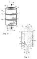
- Fig. 1 is a perspective view of one embodiment for a plasma filter chamber in accordance with the present invention;
- Fig. 2 is a cross sectional view of the embodiment of the plasma filter chamber as seen along the line 2-2 in Fig. 1;
- Fig. 3 is a perspective view of an alternate embodiment for a plasma filter chamber in accordance with the present invention; and
- Fig. 4 is a cross sectional view of the alternate embodiment of the plasma filter chamber as seen along the line 3-3 in Fig. 3.
-
- Referring initially to Fig. 1, one embodiment for a plasma multi-mass filter in accordance with the present invention is shown and is generally designated 10. As shown, the filter 10 includes a
chamber 12 that is surrounded by awall 14. Thechamber 12 has anend 16 and anend 18 and generally defines alongitudinal axis 20 that extends centrally along the length of thechamber 12. The filter 10 also includes a plurality of magnetic coils 22, of which thecoils axis 20. With this configuration, a magnetic field (B) is established in thechamber 12 that extends generally in the direction of theaxis 20. An electrical unit, that may include ring electrodes or a spiral electrode (not shown in Fig. 1), will establish an electrical field (E) in thechamber 12 that is radially oriented and will, therefore, establish crossed electric and magnetic fields (E x B) in thechamber 12. - As intended for the present invention, the filter 10 is used to process a
multi-species plasma 24 that will include at least three species. These species are to be distinguished by their respective mass-charge ratios. As shown in the drawings, charged particles of relatively low mass-charge ratio are designated M1. Charged particles of intermediate mass-charge ratio are designated M2, and charged particles of relatively high-mass charge ratio are designated M3. The subtleties of how the crossed electric and magnetic fields (E x B) cause the particles M1, M2 and M3 to move in thechamber 12 will be best appreciated by cross referencing Fig. 1 with Fig. 2. - Both Fig. 1 and Fig. 2 show that for one embodiment of the present invention the radial distance from the
axis 20 to the wall 14 (designated "a" in the drawings) will vary along the length of the filter 10. Thus, the configuration of thechamber 12 is such that the radial distance "a" atend 18 is larger than the radial distance "a" atend 16. For purposes of further discussion, consider using the character "z" to designate positions along theaxis 20. With this designation scheme, at a position where z is to be designated 2, the radial distance at that position will be az = a2 (r2) and the field strength will be Bz=B2. Where z is to be designated 3, az = a3 (r3) and Bz = B3. As shown in Fig. 2, the configuration of thechamber 12 is such that a2 (r2) is larger than a3 (r3). On the other hand, the magnetic field strength decreases as the corresponding radial distance increases. Accordingly, the magnetic field strength B3, at the position z designated 3, is larger than the magnetic field strength B2, at the position z designated 2. Importantly, this relationship is maintained along theaxis 20 of the filter 10 so that the magnetic flux (az 2Bz) will remain substantially constant in the chamber 12 (e.g. a2 2B2 = a3 2B3). - By predetermining the configuration of the
wall 14, and by controlling the magnitude of the magnetic field in thechamber 12, the expression for a cut-off mass discussed above can be established to effectively divide thechamber 12 into three separate regions. In detail, by establishing predetermined values for Mcz, at specific "z" positions along theaxis 20, the particles M1 in themulti-species plasma 24 can be confined on trajectories which will cause them to transit completely through thechamber 12, for collection in afirst region 26. This can be done so that the particles M1 do not collide with thewall 14. As shown in Fig. 1 and Fig. 2, thefirst region 26 for one embodiment of the filter 10 is located beyond theend 18 of the filter 10. - As implied above, confinement of the particles M1 inside the
chamber 12 is accomplished by establishing specific conditions within the chamber 12 (e.g. Mc2 = er2 2B2/(8*(Vctr-V2)), and Mc3 = e(r3 2-r2 2)B2/(8*V2). Because M1 < Mc2 < Mc3, the conditions for Mc2 and Mc3 will establish trajectories for the particles M1 that prevent the particles M1 from reaching thewall 14 of thechamber 12. On the other hand, because Mc2 < M2 < Mc3, the particles M2 in themulti-species plasma 24 will follow trajectories that take them into asecond region 28, but prevent them from entering afirst region 26. Further, because Mc2 < Mc3 < M3, the particles M3 will follow trajectories that take them into thethird region 30 before they can enter thesecond region 28. Recall, for the conditions just discussed, there is a substantially constant magnetic flux in thechamber 12. Therefore, the magnetic field will have magnetic field lines 32 which diverge for travel along theaxis 20 fromend 16 to end 18. Themagnetic field lines 32a-c shown in Fig. 2 are only exemplary. - Another embodiment for a filter in accordance with the present invention is shown in Fig. 3 and is generally designated 40. As shown, the
filter 40 has a substantially cylindrical shapedchamber 42 that is centered on thelongitudinal axis 20 and is defined by awall 44. Additionally, there are a plurality of magnetic coils 46 (themagnetic coils chamber 42 in a direction that is generally parallel to theaxis 20. An electric field, E, is created inside the chamber which crosses with the magnetic field, B, to establish crossed electric and magnetic fields (E x B) in thechamber 42. As intended for the present invention, the electric field, E, can be generated in a manner well known in the pertinent art using either aring electrode unit 48 or aspiral electrode 50. The particulars of the electric field, E, are perhaps best appreciated with reference to Fig. 4. - In Fig. 4, it will be seen that the electric field, E, is established between the
wall 44, which is at ground, and a positive voltage, Vctr, that extends along theaxis 20. In accordance with the present invention, the electric field, E, has a profile in thechamber 42 that increases outwardly from theaxis 20 through a radial distance "a2" (r2) at a rate ofchange 52. At the radial distance "a2" (r2) there is then a discontinuous decrease in the electric field E, and the electric field then continues to increase outwardly from the radial distance "a2" (r2) to a radial distance "a3" (r3) at a rate ofchange 54. As shown, the rate ofchange 52 is greater than the rate ofchange 54. - Again, using the expression for cut-off mass discussed above, namely Mcz = eaz 2Bz 2/(8Vctr), the chamber 42 (Figs. 3 and 4), like the chamber 12 (Figs. 1 and 2) can be effectively divided into three separate regions. In the case of the
chamber 42, however, this results from the configuration of the electric field, E. Since the ratio of E/r is a constant but changes magnitude between the inner and outer regions, the mass cut-offs for this case must be modified: Mc2 = eB2/(4*(E2/r)) = er2 2B2/(8*(Vctr-V2)) where the average radius is r=r2/2 and the average electric field between the axis and r2 is E2 = (Vctr-V2)/r2 and Mc3 = eB2/(4*(E3/r)) = e(r3 2-r2 2)B2/(8*V2) where the average radius for the outer region is r= (r3 + r2)/2 and the average electric field between r2 and r3 is E3 = V2/(r3-r2) since V3 = 0. The voltages, Vctr on the axis and V2 at r2, are externally controlled to select the respective mass cut-offs. - Referring to Fig. 4, it will be seen that by satisfying the expression Mc2 = er2 2B2/(8*(Vctr-V2)), wherein M1 < Mc2 < Mc3, the particles M1 will be confined to travel on trajectories in the
chamber 42 which do not travel radially more than a distance "a2" (r2) from theaxis 20. Thus, the particles M1 are ejected from thechamber 42 into afirst region 56 that extends generally along theaxis 20. On the other hand, the particles M2 and M3 are not so confined and will have trajectories that take them into asecond region 58 that surrounds thefirst region 56. Specifically, thesecond region 58 is outside thefirst region 56 at more than the distance "a2" (r2) from theaxis 20. - Due to the configuration of the electric field, E, in the
chamber 42, the expression for cut-off mass Mc3 = e(r3 2-r2 2)B2/(8*V2) can be used to confine particles M2 in thesecond region 58, but not the particles M3. Instead, the particles M3 are able to follow trajectories into a third region. In this case, the third region is actually thewall 44. Accordingly, as shown in Fig. 4, when themulti-species plasma 24 is introduced into thechamber 42, the particles M1 will be confined in thechamber 42 for ejection therefrom into thefirst region 56. The particles M2, on the other hand are allowed to proceed with the particles M3 beyond thefirst region 56. Still, the particles M2 will be confined within thechamber 42 and ejected therefrom into thesecond region 58. The particles M3, however, are not confined to either thefirst region 56 or thesecond region 58 and, instead, are able to collide directly into thewall 44. The particles M1, M2 and M3 can then be collected from their respective regions. - While the particular Multi-Mass Filter as herein shown and disclosed in detail is fully capable of obtaining the objects and providing the advantages herein before stated, it is to be understood that it is merely illustrative of the presently preferred embodiments of the invention and that no limitations are intended to the details of construction or design herein shown other than as described in the appended claims.
Claims (20)
- A multi-mass filter for separating particles according to mass which comprises:a chamber;a means for providing a multi-species plasma in said chamber, said multi-species plasma including particles of relatively low mass-charge ratio (M1), particles of intermediate mass-charge ratio (M2), and particles of relatively high mass-charge ratio (M3), said multi-species plasma having a density in said chamber less than a predetermined collisional density; anda means for configuring an electric field crossed with a magnetic field (E x B) in said chamber to establish respective first trajectories for each of said particles (M1), second trajectories for each of said particles (M2), and third trajectories for each of said particles (M3), and to respectively direct each said particle (M1) on its said first trajectory from said chamber into a first region, to direct each said particle (M2) on its said second trajectory from said chamber into a second region, and to direct each said particle (M3) on its said third trajectory from said chamber into a third region to separate said particles (M1, M2 and M3) according to mass-charge ratio.
- A filter as recited in claim 1 wherein said particles M1, M2 and M3, have a collision frequency, νcol, and respective cyclotron frequencies ωm1, ωm2 and ωm3, and wherein ωm1 > ωm2 > ωm3 > νcol with said predetermined collisional density being defined when a ratio between ωm3 and said collision frequency is greater than one (ωm3/ νcol > 1).
- A filter as recited in claim 1 wherein said chamber has a first end and a second end and wherein said multi-species plasma is initially provided in said chamber at a location substantially midway between said first end and said second end.
- A filter as recited in claim 1 wherein said chamber defines an axis, wherein said electric field (E) increases radially from said axis and is generated with a positive voltage Vctr along said axis to extend said electric field (E) substantially radially therefrom, with "az" representing a radial distance from said axis at an axial "z" location, with "Bz" representing a magnetic field strength at an axial "z" location, and with "e" representing a positive ion charge, and wherein said configuring means comprises:a first magnetic means;a second magnetic means; anda control means for activating said first magnetic means and said second magnetic means to maintain az 2Bz substantially constant along said axis with said first magnetic means establishing a cut-off mass Mc3 = e(r3 2-r2 2)B2/(8*V2), with M3 being greater than Mc3 to eject substantially only said particles M3 from said chamber into said third region and said second magnetic means establishing a cut-off mass Mc2 = er2 2B2/(8*(Vctr-V2)), with M2 being greater than Mc2 to eject substantially only said particles M2 from said chamber into said second region.
- A multi-mass filter as recited in claim 4 wherein said first magnetic means comprises at least one magnetic coil mounted in a plane substantially perpendicular to said axis and said second magnetic means comprises at least one magnetic coil mounted in a plane substantially perpendicular to said axis.
- A multi-mass filter as recited in claim 5 wherein a3 (r3) is less than a2 (r2) and B3 is greater than B2.
- A multi-mass filter as recited in claim 1 wherein said chamber defines an axis, wherein said magnetic field (B) is substantially constant along said axis and is oriented substantially parallel thereto, wherein said electric field (E) is generated with a positive voltage Vctr along said axis to extend said electric field (E) substantially radially therefrom, wherein "e" represents a positive ion charge, and wherein said configuring means comprises:a first electrical means for creating an electrical field increasing at a first rate radially outward between said axis and a radial distance a2 (r2) to define said first region therebetween and establish a cut-off mass Mc2 = er2 2B2/(8*(Vctr-V2)) with M3 and M2 being greater than Mc2 to eject particles M3 and M2 from into said first region into said second region; anda second electrical means for creating an electrical field increasing radially outward between said radial distance a2 (r2) and a radial distance a3 (r3) at a second rate to establish a cut-off mass Mc3 = e(r3 2-r2 2)B2/(8*V2) with M3 being greater than Mc3 to eject particles M3 from said second region into said third region.
- A multi-mass filter as recited in claim 7 wherein said first electrical means and said second electrical means are concentric electrode rings, and wherein said electrode rings are coplanar and oriented in a plane with said plane being substantially perpendicular to said axis.
- A multi-mass filter as recited in claim 7 wherein said first electrical means and said second electrical means are combined as a spiral electrode, and wherein said spiral electrode is oriented in a plane with said plane being substantially perpendicular to said axis.
- A multi-mass filter for separating particles according to mass which comprises:a chamber;a means for providing a multi-species plasma including particles of relatively low mass-charge ratio (M1), particles of intermediate mass-charge ratio (M2), and particles of relatively high mass-charge ratio (M3), said multi-species plasma having a density in said chamber less than a predetermined collisional density;a means for establishing an electric field crossed with a magnetic field (E x B) in said chamber to move said particles (M1, M2 and M3) on respective trajectories in said chamber;a first means for configuring (E x B) to confine said particles M1 and M2 in a first vicinity of said chamber; anda second means for configuring (E x B) to confine said particles M2 in a second vicinity of said chamber.
- A multi-mass filter as recited in claim 10 wherein said particles M1, M2 and M3, have a collision frequency, νcol, and respective cyclotron frequencies ωm1, ωm2 and ωm3, and wherein ωm1 > ωm2 > ωm3 > νcol with said predetermined collisional density being defined when a ratio between ωm3 and said collision frequency is greater than one (ωm3/ νcol > 1).
- A multi-mass filter as recited in claim 10 comprising two said chambers, wherein each said chamber has a first end and a second end and wherein said first end of one said chamber is joined with said first end of said other chamber.
- A multi-mass filter as recited in claim 10 wherein said chamber defines an axis and said electric field (E) increases radially from said axis, and wherein said electric field (E) is generated with a positive voltage Vctr along said axis to extend said electric field (E) substantially radially therefrom, with "az" representing a radial distance from said axis at an axial "z" location, with "Bz" representing a magnetic field strength at an axial "z" location, and with "e" representing a positive ion charge, and wherein said first configuring means comprises a first magnetic means, wherein said second configuring means comprises a second magnetic means and said filter further comprises a control means for activating said first magnetic means and said second magnetic means to maintain az 2Bz substantially constant along said axis with said first magnetic means establishing a cut-off mass Mc3 = e(r3 2-r2 2)B2/(8*V2), with M3 being greater than Mc3 to eject substantially only said particles M3 from said chamber into said third region and said second magnetic means establishing a cut-off mass Mc2 = er2 2B2/(8*(Vctr-V2)), with M2 being greater than Mc2 to eject substantially only said particles M2 from said chamber into said second region.
- A multi-mass filter as recited in claim 13 wherein said first magnetic means comprises at least one magnetic coil mounted in a plane substantially perpendicular to said axis and said second magnetic means comprises at least one magnetic coil mounted in a plane substantially perpendicular to said axis.
- A multi-mass filter as recited in claim 10 wherein said chamber defines an axis, wherein said magnetic field (B) is substantially constant along said axis and is oriented substantially parallel thereto, wherein said electric field (E) is generated with a positive voltage Vctr along said axis to extend said electric field (E) substantially radially therefrom, wherein "e" represents a positive ion charge, and wherein said first configuring means creates an electrical field increasing at a first rate extending radially outward between said axis and a radial distance a2 (r2) to define said first region therebetween and establish a cut-off mass Mc2 = er2 2B2/(8*(Vctr-V2)) with M3 and M2 being greater than Mc2 to eject particles M3 and M2 from into said first region into said second region, and said second configuring means creates an electrical field increasing radially outward between said radial distance a2 (r2) and a radial distance a3 (r3) at a second rate to establish a cut-off mass Mc3 = e(r3 2-r2 2)B2/(8*V2) with M3 being greater than Mc3 to eject particles M3 from said second region into said third region.
- A multi-mass filter as recited in claim 15 wherein said first configuring means and said second configuring means include concentric electrode rings, and wherein said electrode rings are coplanar and oriented in a plane with said plane being substantially perpendicular to said axis.
- A multi-mass filter as recited in claim 15 wherein said first configuring means and said second configuring means are combined as a spiral electrode, and wherein said spiral electrode is oriented in a plane with said plane being substantially perpendicular to said axis.
- A method for separating particles according to mass which comprises the steps of:providing a multi-species plasma in a chamber, said multi-species plasma being below a predetermined collisional density and including particles of relatively low mass-charge ratio (M1), particles of intermediate mass-charge ratio (M2), and particles of relatively high mass-charge ratio (M3), wherein said particles M1, M2 and M3, have a collision frequency,νcol, and respective cyclotron frequencies ωm1, ωm2 and ωm3, and wherein ωm1 > ωm2 > ωm3 > νcol with said predetermined collisional density being defined when a ratio between ωm3 and said collision frequency is greater than one (ωm3/ νcol > 1); andconfiguring an electric field crossed with a magnetic field (E x B) in said chamber to establish respective first trajectories for each of said particles (M1), second trajectories for each of said particles (M2), and third trajectories for each of said particles (M3), and to respectively direct each said particle (M1) on its said first trajectory from said chamber into a first region, to direct each said particle (M2) on its said second trajectory from said chamber into a second region, and to direct each said particle (M3) on its said third trajectory from said chamber into a third region to separate said particles (M1, M2 and M3) according to mass.
- A method as recited in claim 18 wherein said chamber defines an axis, wherein said electric field (E) increases radially from said axis and is generated with a positive voltage Vctr along said axis to extend said electric field (E) substantially radially therefrom, with "az" representing a radial distance from said axis at an axial "z" location, with "Bz" representing a magnetic field strength at an axial "z" location, and with "e" representing a positive ion charge, and wherein said configuring step comprises:using first magnetic means and a second magnetic means; andactivating said first magnetic means and said second magnetic means to maintain az 2Bz substantially constant along said axis with said first magnetic means establishing a cut-off mass Mc3 = e(r3 2-r2 2)B2/(8*V2), with M3 being greater than Mc3 to eject substantially only said particles M3 from said chamber into said third region and said second magnetic means establishing a cut-off mass Mc2 = er2 2B2/(8*(Vctr-V2)), with M2 being greater than Mc2 to eject substantially only said particles M2 from said chamber into said second region.
- A method as recited in claim 18 wherein said chamber defines an axis, wherein said magnetic field (B) is substantially constant along said axis and is oriented substantially parallel thereto, wherein said electric field (E) is generated with a positive voltage Vctr along said axis to extend said electric field (E) substantially radially therefrom, wherein "e" represents a positive ion charge, and wherein said configuring step comprises:creating an electrical field increasing at a first rate radially outward between said axis and a radial distance a2 (r2) to define said first region therebetween and establish a cut-off mass Mc2 = er2 2B2/(8*(Vctr-V2)) with M3 and M2 being greater than Mc2 to eject particles M3 and M2 from into said first region into said second region; andcreating an electrical field increasing radially outward between said radial distance a2 (r2) and a radial distance a3 (r3) at a second rate to establish a cut-off mass Mc3 = e(r3 2-r2 2)B2/(8*V2) with M3 being greater than Mc3 to eject particles M3 from said second region into said third region.
Applications Claiming Priority (2)
| Application Number | Priority Date | Filing Date | Title |
|---|---|---|---|
| US643204 | 1996-05-02 | ||
| US09/643,204 US6293406B1 (en) | 2000-08-21 | 2000-08-21 | Multi-mass filter |
Publications (2)
| Publication Number | Publication Date |
|---|---|
| EP1220286A2 true EP1220286A2 (en) | 2002-07-03 |
| EP1220286A3 EP1220286A3 (en) | 2003-04-02 |
Family
ID=24579795
Family Applications (1)
| Application Number | Title | Priority Date | Filing Date |
|---|---|---|---|
| EP01202935A Withdrawn EP1220286A3 (en) | 2000-08-21 | 2001-08-02 | Multi-mass filter |
Country Status (3)
| Country | Link |
|---|---|
| US (2) | US6293406B1 (en) |
| EP (1) | EP1220286A3 (en) |
| JP (1) | JP3738207B2 (en) |
Families Citing this family (10)
| Publication number | Priority date | Publication date | Assignee | Title |
|---|---|---|---|---|
| GB0025016D0 (en) | 2000-10-12 | 2000-11-29 | Micromass Ltd | Method nad apparatus for mass spectrometry |
| JP4854842B2 (en) * | 2000-10-20 | 2012-01-18 | 独立行政法人科学技術振興機構 | Particle control method |
| US6773558B2 (en) * | 2002-10-15 | 2004-08-10 | Archimedes Technology Group, Inc. | Fluorine generator |
| KR100766093B1 (en) * | 2005-07-13 | 2007-10-11 | 삼성전자주식회사 | Neutral beam etching device for seperating and accelating plasma |
| US7504031B2 (en) * | 2005-08-16 | 2009-03-17 | Dunlap Henry R | Ion separation and gas generation |
| US7223335B2 (en) * | 2005-08-16 | 2007-05-29 | Dunlap Henry R | Ion separation |
| US20070095726A1 (en) * | 2005-10-28 | 2007-05-03 | Tihiro Ohkawa | Chafftron |
| CN104520453A (en) | 2011-11-10 | 2015-04-15 | 先进磁工艺股份有限公司 | Magneto-plasma separator and method for separation |
| WO2013089080A1 (en) * | 2011-12-12 | 2013-06-20 | 宇部興産株式会社 | Mixture separation method and separation device |
| US20140141619A1 (en) * | 2012-11-19 | 2014-05-22 | Tokyo Electron Limited | Capacitively coupled plasma equipment with uniform plasma density |
Citations (1)
| Publication number | Priority date | Publication date | Assignee | Title |
|---|---|---|---|---|
| US6096220A (en) * | 1998-11-16 | 2000-08-01 | Archimedes Technology Group, Inc. | Plasma mass filter |
Family Cites Families (11)
| Publication number | Priority date | Publication date | Assignee | Title |
|---|---|---|---|---|
| SE338962B (en) | 1970-06-04 | 1971-09-27 | B Lehnert | |
| US3942975A (en) * | 1971-08-18 | 1976-03-09 | The Boeing Company | Method and apparatus for reducing matter to constituent elements and separating one of the elements from the other elements |
| US3845300A (en) * | 1973-04-18 | 1974-10-29 | Atomic Energy Commission | Apparatus and method for magnetoplasmadynamic isotope separation |
| US4107524A (en) * | 1975-12-04 | 1978-08-15 | Book David L | High atomic weight isotope separator |
| US4093856A (en) * | 1976-06-09 | 1978-06-06 | Trw Inc. | Method of and apparatus for the electrostatic excitation of ions |
| FR2363364A1 (en) * | 1976-09-07 | 1978-03-31 | Thomson Csf | ISOTOPIC SEPARATION PROCESS AND INSTALLATION FOR ITS IMPLEMENTATION |
| US4213043A (en) * | 1977-07-20 | 1980-07-15 | Trw Inc. | Method for flowing a large volume of plasma through an excitation region |
| FR2705584B1 (en) * | 1993-05-26 | 1995-06-30 | Commissariat Energie Atomique | Isotopic separation device by ion cyclotron resonance. |
| US5681434A (en) | 1996-03-07 | 1997-10-28 | Eastlund; Bernard John | Method and apparatus for ionizing all the elements in a complex substance such as radioactive waste and separating some of the elements from the other elements |
| GB9704077D0 (en) | 1996-03-15 | 1997-04-16 | British Nuclear Fuels Plc | Improvements in and relating to processing |
| US5868909A (en) | 1997-04-21 | 1999-02-09 | Eastlund; Bernard John | Method and apparatus for improving the energy efficiency for separating the elements in a complex substance such as radioactive waste with a large volume plasma processor |
-
2000
- 2000-08-21 US US09/643,204 patent/US6293406B1/en not_active Expired - Fee Related
-
2001
- 2001-05-17 US US09/860,161 patent/US6386374B1/en not_active Expired - Fee Related
- 2001-08-02 EP EP01202935A patent/EP1220286A3/en not_active Withdrawn
- 2001-08-20 JP JP2001249300A patent/JP3738207B2/en not_active Expired - Fee Related
Patent Citations (1)
| Publication number | Priority date | Publication date | Assignee | Title |
|---|---|---|---|---|
| US6096220A (en) * | 1998-11-16 | 2000-08-01 | Archimedes Technology Group, Inc. | Plasma mass filter |
Also Published As
| Publication number | Publication date |
|---|---|
| US6293406B1 (en) | 2001-09-25 |
| JP2002177814A (en) | 2002-06-25 |
| US6386374B1 (en) | 2002-05-14 |
| EP1220286A3 (en) | 2003-04-02 |
| US20020020657A1 (en) | 2002-02-21 |
| JP3738207B2 (en) | 2006-01-25 |
Similar Documents
| Publication | Publication Date | Title |
|---|---|---|
| JP3492960B2 (en) | Plasma mass filter | |
| US6322706B1 (en) | Radial plasma mass filter | |
| US6251281B1 (en) | Negative ion filter | |
| EP1220293B1 (en) | Tandem plasma mass filter | |
| US6293406B1 (en) | Multi-mass filter | |
| CA2313756C (en) | Plasma mass filter | |
| EP1723665A1 (en) | Mass separator with controlled input | |
| US6214223B1 (en) | Toroidal plasma mass filter | |
| US6726844B2 (en) | Isotope separator | |
| US6730231B2 (en) | Plasma mass filter with axially opposed plasma injectors | |
| JP2001179081A (en) | Plasma filter with helical magnetic field | |
| US6217776B1 (en) | Centrifugal filter for multi-species plasma | |
| US6787044B1 (en) | High frequency wave heated plasma mass filter | |
| US6723248B2 (en) | High throughput plasma mass filter | |
| US6521888B1 (en) | Inverted orbit filter | |
| EP1351273B1 (en) | Band gap plasma mass filter | |
| US20040112833A1 (en) | Band gap mass filter with induced azimuthal electric field | |
| EP1220289A2 (en) | Plasma mass selector |
Legal Events
| Date | Code | Title | Description |
|---|---|---|---|
| PUAI | Public reference made under article 153(3) epc to a published international application that has entered the european phase |
Free format text: ORIGINAL CODE: 0009012 |
|
| AK | Designated contracting states |
Kind code of ref document: A2 Designated state(s): AT BE CH CY DE DK ES FI FR GB GR IE IT LI LU MC NL PT SE TR |
|
| AX | Request for extension of the european patent |
Free format text: AL;LT;LV;MK;RO;SI |
|
| PUAL | Search report despatched |
Free format text: ORIGINAL CODE: 0009013 |
|
| AK | Designated contracting states |
Kind code of ref document: A3 Designated state(s): AT BE CH CY DE DK ES FI FR GB GR IE IT LI LU MC NL PT SE TR Designated state(s): AT BE CH CY DE DK ES FI FR GB GR IE IT LI LU MC NL PT SE TR |
|
| AX | Request for extension of the european patent |
Extension state: AL LT LV MK RO SI |
|
| RIC1 | Information provided on ipc code assigned before grant |
Ipc: 7B 01D 59/48 B Ipc: 7H 01J 37/32 B Ipc: 7H 01J 49/28 A |
|
| 17P | Request for examination filed |
Effective date: 20030718 |
|
| AKX | Designation fees paid |
Designated state(s): DE FR GB |
|
| RAP1 | Party data changed (applicant data changed or rights of an application transferred) |
Owner name: ARCHIMEDES OPERATING, LLC |
|
| STAA | Information on the status of an ep patent application or granted ep patent |
Free format text: STATUS: THE APPLICATION HAS BEEN WITHDRAWN |
|
| 18W | Application withdrawn |
Effective date: 20060505 |