EP1220501A2 - Group creation for wireless communication terminals - Google Patents
Group creation for wireless communication terminals Download PDFInfo
- Publication number
- EP1220501A2 EP1220501A2 EP01660224A EP01660224A EP1220501A2 EP 1220501 A2 EP1220501 A2 EP 1220501A2 EP 01660224 A EP01660224 A EP 01660224A EP 01660224 A EP01660224 A EP 01660224A EP 1220501 A2 EP1220501 A2 EP 1220501A2
- Authority
- EP
- European Patent Office
- Prior art keywords
- group
- wireless
- user
- signal
- users
- Prior art date
- Legal status (The legal status is an assumption and is not a legal conclusion. Google has not performed a legal analysis and makes no representation as to the accuracy of the status listed.)
- Granted
Links
Images


Classifications
-
- H—ELECTRICITY
- H04—ELECTRIC COMMUNICATION TECHNIQUE
- H04W—WIRELESS COMMUNICATION NETWORKS
- H04W4/00—Services specially adapted for wireless communication networks; Facilities therefor
- H04W4/06—Selective distribution of broadcast services, e.g. multimedia broadcast multicast service [MBMS]; Services to user groups; One-way selective calling services
- H04W4/08—User group management
-
- H—ELECTRICITY
- H04—ELECTRIC COMMUNICATION TECHNIQUE
- H04B—TRANSMISSION
- H04B13/00—Transmission systems characterised by the medium used for transmission, not provided for in groups H04B3/00 - H04B11/00
- H04B13/005—Transmission systems in which the medium consists of the human body
-
- H—ELECTRICITY
- H04—ELECTRIC COMMUNICATION TECHNIQUE
- H04M—TELEPHONIC COMMUNICATION
- H04M1/00—Substation equipment, e.g. for use by subscribers
- H04M1/72—Mobile telephones; Cordless telephones, i.e. devices for establishing wireless links to base stations without route selection
- H04M1/724—User interfaces specially adapted for cordless or mobile telephones
- H04M1/72403—User interfaces specially adapted for cordless or mobile telephones with means for local support of applications that increase the functionality
- H04M1/72409—User interfaces specially adapted for cordless or mobile telephones with means for local support of applications that increase the functionality by interfacing with external accessories
- H04M1/72412—User interfaces specially adapted for cordless or mobile telephones with means for local support of applications that increase the functionality by interfacing with external accessories using two-way short-range wireless interfaces
-
- H—ELECTRICITY
- H04—ELECTRIC COMMUNICATION TECHNIQUE
- H04W—WIRELESS COMMUNICATION NETWORKS
- H04W40/00—Communication routing or communication path finding
- H04W40/24—Connectivity information management, e.g. connectivity discovery or connectivity update
- H04W40/246—Connectivity information discovery
-
- H—ELECTRICITY
- H04—ELECTRIC COMMUNICATION TECHNIQUE
- H04W—WIRELESS COMMUNICATION NETWORKS
- H04W40/00—Communication routing or communication path finding
- H04W40/24—Connectivity information management, e.g. connectivity discovery or connectivity update
- H04W40/26—Connectivity information management, e.g. connectivity discovery or connectivity update for hybrid routing by combining proactive and reactive routing
-
- H—ELECTRICITY
- H04—ELECTRIC COMMUNICATION TECHNIQUE
- H04W—WIRELESS COMMUNICATION NETWORKS
- H04W40/00—Communication routing or communication path finding
- H04W40/24—Connectivity information management, e.g. connectivity discovery or connectivity update
- H04W40/32—Connectivity information management, e.g. connectivity discovery or connectivity update for defining a routing cluster membership
-
- H—ELECTRICITY
- H04—ELECTRIC COMMUNICATION TECHNIQUE
- H04W—WIRELESS COMMUNICATION NETWORKS
- H04W8/00—Network data management
- H04W8/005—Discovery of network devices, e.g. terminals
-
- H—ELECTRICITY
- H04—ELECTRIC COMMUNICATION TECHNIQUE
- H04W—WIRELESS COMMUNICATION NETWORKS
- H04W92/00—Interfaces specially adapted for wireless communication networks
- H04W92/16—Interfaces between hierarchically similar devices
- H04W92/18—Interfaces between hierarchically similar devices between terminal devices
Definitions
- the invention relates to a group communication method and a device, a method for forming of a group of terminal devices.
- PDAs personal digital assistants
- pagers pagers
- PANs Personal Area Networks
- a low-frequency carrier is used.
- a prototype PAN system allows users to exchange electronic business cards by shaking hands.
- PAN devices are used in worn objects. They are watches, credit cards, eyeglasses, identification badges, belts, waist packs, and shoe insert. Head-mounted PAN devices include headphones, hearing aids, microphones, and head-mounted displays. Shirt pocket PAN devices operate as identification badges. The wristwatch operates as a location for a display, a microphone, a camera, and a speaker. PAN devices incorporating sensors provide medical monitoring for bodily functions (heartbeat, blood pressure, and respiratory rate). Wallet-based PAN devices store information and identify the possessor. Shoe inserts are self-powered and provide a data-link to remote PAN devices located in the workstations and floor transponders that detect the location and identity of people.
- cellular telephone systems providing mobile telephone services.
- the cellular telephone systems provide services that allow subscribers of these systems to increase their accessibility and be reachable, potentially at all times, and as long as the subscribers remain in the service areas covered by their systems.
- a person desiring to contact the cellular subscriber would simply dial the phone number of the cellular subscriber to contact the subscriber at the subscriber's cellular telephone. As long as the cellular subscriber kept the cellular telephone powered on the subscriber would be accessible when located within the coverage area of the cellular system.
- a group call is a conference call in which all participants may talk in turn and hear one another.
- An individual mobile radio may belong to a plurality of groups programmed into the mobile radio. The system keeps a file on the base stations associated with the group number of each group.
- a group call may cover one, several or all base stations within the area of a mobile exchange or a plurality of mobile exchanges.
- SMS Short message services
- GSM Global System for Mobile communications
- GPRS General Packet Radio Service
- a wireless communication terminal and a method for creation or establishment of a group.
- a method for establishing a group of at least two wireless terminals for wireless group communication between the at least two wireless terminals comprising the steps of:
- a wireless communication terminal for group communication with at least one other wireless terminal, comprising:
- the wireless communication link is preferably a low power radio frequency link, such as a Bluetooth link.
- the establishment of the group is saved in the memory of each terminal device of the group, whereafter activation of a group communication, such as making a group phone call, or a group messaging in the form of sending text messages or images to the whole group, can be done by activation of the group communication to that particular group.
- the memory can be arranged in a similar manner as a telephone directory in a mobile phone or as is known as the Contacts directory in e.g. the Nokia 9110 Communicator.
- a vicinity of the wireless terminals is detected using the communication over the wireless link. Detecting a vicinity of the wireless terminals includes entering a group creation mode in at least two of the wireless terminal. After the user has entered the mode, the method includes inquiring the vicinity of the wireless terminals using the wireless communication to transmit a message from the wireless terminal that has first entered the mode to the second wireless terminal that has entered the mode. The message includes information about the first wireless terminal that initiates the process and it may further include information about the group creation.
- the entering the group-creating mode preferably includes touching an electrode located on or being in connection to the terminal.
- the entering into the group creation mode may also include selecting the mode from a menu of the wireless terminal or pressing a particular button.
- detecting the physical contact between the users preferably includes transferring a signal via the physical contact between the users of the wireless terminals using the first circuit in the wireless terminals.
- the transferred signal is generated in a signal transceiver, such as a PAN transceiwer.
- the generated signal is transferred to a body of the first user from an electrode connected to the signal transceiver and to a body of a second user when the users are physically connected.
- a transceiver at the wireless terminal of the second user detects the generated signal.
- the signal is received via the bodies of possibly other physically connected users to respective transceivers in their terminals by touching an electrode at their respective terminals.
- the signal is preferably a low-frequency signal, e.g. less than one megahertz.
- the physical contact may include a handshake. It may also include another type of contact between the users that may allow the signal to pass between the users.
- the establishment of the group of the physically connected user of the wireless terminals may be confirmed using a message that may be transmitted using the
- a wireless terminal for enabling users to form a group communication.
- the wireless terminal includes a first circuit or transceiver which is connected to the central controller of the terminal.
- the first circuit is used for communication between at least two users of a wireless terminal when there is a physical contact between the users in order to form a group.
- the wireless terminal includes a second circuit or transceiver which is connected to the central controller.
- the second circuit is for a wireless group communication between the at least two wireless terminals of the established group.
- the second circuit is preferably a short-range radio transceiver.
- the first circuit is preferably a PAN transceiver and a group creation electrode.
- the first circuit may include a switch to trigger the communication.
- the switch may also trigger the creation of the group.
- the central controller may include a processor (CPU), a memory, an input and an output.
- the physical contact between at least two users may be a handshake between the persons.
- the physical contact may also be another type of contact between the users that allows the signal to pass between the users.
- the physical contact may be any contact between the users that enables a small electrical current to flow from a first body of a first user to a second body(s) of a second user(s).
- the physical contact may also be any contact where a body can exchange digital information coupling capacitively small currents through the body.
- the signal may be a low frequency signal that can be electric current.
- wireless terminals establish a communication group.
- a user 100 has a wireless terminal 300 in his possession.
- the group has at least two, but preferably several wireless terminals, for example, wireless terminal 300, 301, and 302.
- Wireless terminal 300 may, for example, be a mobile, a Personal Digital Assistant (PDA), a laptop computer, or any other terminal equipped with a short-range radio communication transceiver or low-power radio communication transceiver.
- An arm 101 (111 and 121 respectively) of user 100 (110 and 120) may be used in group creation to transfer a signal between the users when the users have a physical connection.
- One of the wireless terminals, e.g. wireless terminal 300 may function as a master that may have administrative tasks in the group creation.
- a physical contact 200 is illustrated. Users 100, 110, and 120 touch one another by their hands whereby a physical contact 200 between the users 100, 110, and 120 is established.
- the physical connection 200 preferably allows a signal to transfer between the users 100, 110, and 120 by capacitively coupling small currents (picoampers) through the body caused by the contact.
- the source of the signal can be a PAN transceiver in contact with an electrode that one of the users touches (and likewise the signal may be received by a PAN transceiver that another one of the user is in touch with via an electrode).
- the signal or signals may be transmitted via physical contact 200 between, for example, user 100 and user 120, in which case only users 100 and 120 would be included in the group, but user 110 would be excluded.
- the signal or signals may also be transmitted via physical contact 200 between all users 100, 110 and 120 under any kind of combination of users, such as by a chain contact.
- the signal may be transferred from user 100 to users 110 and 120 concurrently.
- the signal may be transferred from user 120 via physical contact 200 to user 100.
- Physical contact 200 may, for example, be a handshake, touching another user's body by touching another user's skin, or any other contact between users where human body can exchange digital information by capacitively coupling small currents (picoampers) through the body.
- User 100 may hold wireless terminal 300.
- User 100 can also press an electrode located on the terminal 300 or connected to the terminal (e.g.
- Respectively user 120 may hold wireless terminal 302 and hold a finger on an electrode or sensor which will receive the signal transmitted from the electrode of terminal 300.
- the user 120 may have an electrode or sensor connected to his body (e.g. to his chest) where the electrode is connected by wire to terminal 302. Every user that is to participate in the group to be established should touch the electrode of his terminal at the same time as being in contact with another user so that a signal is transmitted from one terminal (from the electrode) and received at the other terminals (at their respective electrodes) using the users as a signal transfer medium.
- user 110 would also need to touch the electrode of his terminal to become a member of the group when in physical contact with the other users 100 and 120.
- Wireless terminal 300 may have a short-range radio communication circuit or transceiver, which here will be called the second circuit.
- the second circuit is for example a Low Power Radio Frequency (LPRF) transceiver 310 such as a Bluetooth transceiver, utilising an antenna 320, which is connected to the transceiver 310 for radio transmission of information over a radio link.
- LPRF Low Power Radio Frequency
- the wireless terminal may have another antenna (not shown) that can be used to transmit information relating to other radio communication than short-range radio communication, for example, it may be the antenna for communication over a cellular mobile telephone network.
- a central controller CC 330 is connected to LP transceiver 310. It may include components that are used to control and operate wireless terminal 300 such as a Central Processor Unit (CPU) 331, a RAM memory 332, input / output (I/O) electronics 333, and be connected to a user interface 334 comprising e.g. a keypad and display. Further a PAN transceiver 340 is connected to the CC 330. In following the PAN transceiver is called a first circuit.
- the first circuit may include a group creation electrode 350.
- the PAN transceiver 340 may be used to send and receive signals that are transferred through human bodies and possibly through physical contact 200.
- Group creation electrode 350 may be used to couple a surface of human body such as a finger to establish a connection, for example, from a first PAN transceiver (located e.g. in wireless terminal 300 in Fig. 2) and first user's body to second user's body and thereby to a second PAN transceiver (located e.g. in wireless terminal 302 in Fig. 2).
- a ground or earth may be used to establish a circuit that may enable signal (current) to transfer between the users.
- the return path, earth/ground may include conductors and dielectrics in the environment that are in close proximity to the PAN transmitters.
- the earth ground may be electrically isolated to prevent shorting of the communication circuit.
- the wireless terminal 300 preferably also includes a power source such as a chargeable and releasable battery 370.
- the user interface 334 of the wireless terminal 300 preferably includes control buttons for controlling other functions of the terminal, for example, browsing the menu or selecting icons, as well as a display for display messages and information relating to the establishment of a group as well as relating to a group communication taking place.
- a controller 342 is connected to a transceiver 343 and to a switch 344.
- the controller 342 can trigger the transceiver 343 to send a signal and it may activate 343 transceiver either to send or receive the signal.
- the switch 344 is used to indicate controller 342 to trigger the transceiver 343 to transmit and receive.
- the switch 344 is connected to an electrode 350.
- the electrode 350 may shuttle being attached to switch 344.
- the switch 344 indicates controller 342 to give a command to transceiver 343 to turn on for transceiving a signal.
- Switch 344 may have a restoring force such as a spring to set the electrode 350 to the standby mode when, for example, the user has lifted his finger from the electrode 350.
- FIG. 4B another embodiment of a PAN transceiver 340' is illustrated.
- a controller 342 is connected to the transceiver 343.
- the controller may set transceiver 343 to send the signal or it may activate transceiver 343 either to send or receive the signal.
- an electrode 350 is connected directly to the transceiver 343.
- the electrode 350 may also have a connection (not shown) to controller 342.
- the PAN transceiver 340' may now be triggered or activated to transmit a signal that will be conducted to the body of the person via the electrode 350.
- the activation can be done by detecting the user touching the electrode, which could be done by e.g. detecting change of capacity at the electrode with the controller 342.
- the signal transmitted from the electrode 350 is for example a ping signal.
- the ping signal is preferably a low-frequency signal (less that one megahertz), for example, about 100 - 1000 KHz AC pulse.
- the length of the signal will be such that it may be transferable and detectable.
- a low frequency carrier is used so no energy is propagated, minimizing remote eavesdropping and interference by neighboring PANs.
- the transmitted ping signal may be used for inquiring or pinging information by transmitting it from a first wireless user terminal to a second wireless user terminal (there can be more users and terminals than just two).
- the purpose of transmitting the ping signal is to prepare for a second communication so that the second circuit communication, for example a Bluetooth communication, would not require an inquiry or an extra inquiry when initiating the communication. This speeds up the Bluetooth communication and the setting up of the connection does not consume band of the Bluetooth frequency.
- the signal includes an identifier of the transmitting transceiver, such as an address of second circuit, for example a Bluetooth address 501.
- each Bluetooth transceiver is allocated a unique 48-bit Bluetooth device address (BD_ADDR).
- the signal may also, though not necessarily, include a clock offset 502.
- Clock offset 502 is used for synchronization with other units.
- the signal may also, though not necessarily, include a class of device 503 such as is known from Bluetooth.
- Class of device 503 may be 24-bit field containing the class of device of the unit that sends the Frequency Hop Synchronization (FHS) packet.
- FHS Frequency Hop Synchronization
- the user 100 may enter a group creation mode at wireless terminal 300 (step 600).
- the user 100 enters the group creation mode by touching or pressing the electrode 350.
- the user 100 may enter the group creation mode by selecting the mode from a menu of the wireless terminal 100.
- the user terminal 300 inquires other terminals that may be presence, for example, wireless terminals 301 and 302 (see Fig. 1) that are in the vicinity (step 610).
- the user terminal 300 transmits a message to the terminals that are located within an operation range of the terminal, such as terminals 301 and 302 by the second circuit transmission (i.e.
- the wireless user terminal 300 that transmits the first inquiring message may be termed as a master.
- the master terminal 300 receives a reply message from the devices that are able to establish the group and that are located within the range.
- the master terminal selects at least one of the terminals 301 and 302 and sends a message over the wireless link indicating the selection to the terminals 301 and 302 via second circuit transmission.
- the users confirm the group formation by physical contact 200 of the users (100, 110, 120) and the master terminal 300 sends a signal such as a ping signal to wireless terminals 301 and 302 (step 630).
- the physical contact 200 may be, for example, a handshake, touching by a finger other user's skin, or any kind of contact between users that may provide current (signal) to flow between the bodies of the users. Via the physical contact an electric circuit is completed, allowing pico amp signal to pass from the transmitter of the first circuit of the master user (100) through the body of the master user (100), to the body of the other user(s) (110 and/or 120), and to the receiver of the other user(s) terminal(s) (301 and/or 302), such as to PAN transceiver 340 in terminals 301 and 302. At this stage the users 100, 110, 120 and the electrodes 350 are coupled.
- a portion of the user's body, for example, a finger should touch the group creation electrodes 350 at this point (step 630).
- This process step may really confirm that there exists physical contact 200 between the users of the group (or that are to form the group).
- the user terminals detect the received signal and register it.
- the master terminal 300 sends a query to each wireless terminal(s) (301 and/or 302) to ensure each terminal (that participated in the preparation for establishing a group in step 610) successfully received the ping signal (step 640). If some wireless terminal(s) (301 and/or 302) has not received the ping signal, the master 300 will send that terminal a request to send the signal (step 650) or to verify that that terminal does not want to participate in the group.
- a particular terminal has not responded by sending a message (over the wireless communication) to the master 300, that terminal is excluded from the group (or could be separately agreed to become a member of the group by a separate wireless communication between the master and that terminal).
- the master 300 may continue the loop of steps 640 and 650 until the pinging process has been determined successful by replies from the other terminals.
- the group is established using communication over the second circuit (step 660).
- the master 300 informs at step 670 the other wireless terminals (310 and/or 302) about the successful group creation preferably by use of the second circuit communication. Having established the group the group information is stored in the memory of the central controller CC, such as in a telephone directory like group directory.
- a signalling diagram of an establishment of a group is illustrated.
- user terminal node 700 i.e. a first wireless user terminal transmits a message 720 by use of the second circuit (e.g. Bluetooth) of the terminal.
- the message includes information about the establishment of the group, and can further include information about the transmitter, protocols, devices, etc.
- Another user terminal node 710 i.e. a second wireless user terminal receives and detects the message likewise by use of the second circuit of the second user terminal. Users then form a physical contact 200 between each other.
- User terminal node 710 then sends signal 740 to user terminal node 700 over the established physical contact 200 using the first circuit.
- User terminal node 700 receives over the physical contact and detects this signal 740 using the first circuit (e.g. PAN transceiver).
- User terminal node 710 transmits a message 750 to user terminal node 700 to acknowledge the group formation.
- the group creation may not require the physical connection of all users at the same time, but in steps. For example, let us assume that wireless terminal (a) will send a ping signal, that will be received at wireless terminals (b) and (d), but not at wireless terminal (c). Next, wireless terminal (c) will send a ping signal that will be received and detected at wireless terminals (b) and (d), but not at wireless terminal (a), so there is missing a direct contact between terminals (a) and (c). However, since there is a connection from wireless terminals (a) and (c) to wireless terminals (b) and (d), there is an indirect connection between (a) and (c) indicating the group establishment. Thus all four terminals (a) - (d) will be forming the group although not all users were in physical contact at the same time, but at different times.
- the order and the amount of the signals and messages may vary.
- the users may have come in physical contact 200 with one another, whereby first wireless terminal sends a signal by the first circuit (PAN), and the group may be formed based on the trigger signal sent by the PAN transceiver.
- the first wireless terminal may send the message by use of the second circuit and the second wireless user terminal receives it over the wireless communication (Bluetooth) and users then establish physical contact 200 and send the group creation signal to first wireless terminal by the circuit (PAN).
- the first wireless terminal receives the group creation signal and confirm the establishment of the group by transmitting the confirming message to second wireless terminal by use of the second circuit (Bluetooth).
- the first wireless terminal may send the message using the second circuit and a second and a third wireless terminal receive the message and reply to it.
- the second wireless terminal may now send a signal to first and third wireless terminals via the established physical contact 200 between the users of the wireless terminals. After the signal is sent, the wireless terminals may communicate several messages between themselves using the second circuit and finally the group may be formed and communication may continue.
- the menu at the display of a wireless user terminal is shown when the user selects the group creation mode.
- the wireless user terminal 300 preferably has a user interface 334' having a display where the menu is shown to the user.
- Command "Others” may indicate the selection of some other command than those relating to the group formation, for example, edit short-range network settings.
- wireless terminal 300 sends the inquiring message and the group establishment continues as described above.
- the information of the terminals that are about to establish the group is shown.
- the text shows the user that wireless terminals 1, 2, and 3 may form a group.
- the user acting now as the master may decide whether he wants to establish the group.
- the user may also decide whether he wants to exclude some terminal from the group.
- the user of the master terminal may also be allowed to cancel the establishment of the group.
- the identifier used in the signal may be a phone number or International mobile Equipment Identity (IMEI) and the second circuit and further the second circuit communication in the group may be Global Standard for Mobile / Groupe Speciale Mobile (GSM), General Packet Radio (GPRS) or Universal Mobile Telephone System (UMTS).
- GSM Global Standard for Mobile / Groupe Speciale Mobile
- GPRS General Packet Radio
- UMTS Universal Mobile Telephone System
Abstract
Description
- The invention relates to a group communication method and a device, a method for forming of a group of terminal devices.
- Electronic devices become smaller, lower in power requirements, and less expensive, the bodies are adorned with personal information and communication appliances. Such devices include cellular phones, personal digital assistants (PDAs), pocket video games, and pagers. The concept of Personal Area Networks (PANs) is known to illustrate how electronic devices on and near the human body can exchange digital information by capacitively coupling small currents through the body. A low-frequency carrier is used. A prototype PAN system allows users to exchange electronic business cards by shaking hands.
- PAN devices are used in worn objects. They are watches, credit cards, eyeglasses, identification badges, belts, waist packs, and shoe insert. Head-mounted PAN devices include headphones, hearing aids, microphones, and head-mounted displays. Shirt pocket PAN devices operate as identification badges. The wristwatch operates as a location for a display, a microphone, a camera, and a speaker. PAN devices incorporating sensors provide medical monitoring for bodily functions (heartbeat, blood pressure, and respiratory rate). Wallet-based PAN devices store information and identify the possessor. Shoe inserts are self-powered and provide a data-link to remote PAN devices located in the workstations and floor transponders that detect the location and identity of people.
- Advances in telecommunication systems technology have resulted in a variety of systems and services being available for system users. These systems include cellular telephone systems providing mobile telephone services. The cellular telephone systems provide services that allow subscribers of these systems to increase their accessibility and be reachable, potentially at all times, and as long as the subscribers remain in the service areas covered by their systems.
- In a cellular system, a person desiring to contact the cellular subscriber would simply dial the phone number of the cellular subscriber to contact the subscriber at the subscriber's cellular telephone. As long as the cellular subscriber kept the cellular telephone powered on the subscriber would be accessible when located within the coverage area of the cellular system.
- Normally the system sets up a call between the cellular telephone or a so-called mobile terminal and another mobile terminal or a subscriber of a public switched telephone network PSTN. Dialing the subscriber number of the mobile terminal or the like sets up a call to the given mobile terminal. In group calls the whole group is called with a single dialed number, i.e. a group number. A group call is a conference call in which all participants may talk in turn and hear one another. An individual mobile radio may belong to a plurality of groups programmed into the mobile radio. The system keeps a file on the base stations associated with the group number of each group. A group call may cover one, several or all base stations within the area of a mobile exchange or a plurality of mobile exchanges.
- Some mobile networks include short message services, e.g. SMS is a bi-directional service in GSM for short alphanumeric messages or data in similar form. In SMS it is possible to deliver a message to the mobile terminal even during an established call, and to deliver a message using so-called store-and-forward service, in which the message is stored in the network, if the mobile terminal is unavailable, and forwarded shortly after the mobile terminal can be reached again. In the traditional GSM system data services are based on circuit switched technology providing maximum data transfer rate of 9,6 kbit/s for transparent and non-transparent bearer services for data communication. Along with an increasing data volume, demand for higher transfer rates has arisen so that the GSM system has been developed to include as an extension the so-called General Packet Radio Service (GPRS) as a packet switched data service.
- Accordingly, it is an object of the present invention to enable users and provide a method and a terminal for group communication and for establishing the group between the users based on a physical contact of the users.
- In accordance with the invention there is provided a wireless communication terminal and a method for creation or establishment of a group.
- According to a first aspect of the invention there is provided a method for establishing a group of at least two wireless terminals for wireless group communication between the at least two wireless terminals, comprising the steps of:
- bringing the users of the at least two wireless terminals into a physical contact;
- detecting the physical contact between the users of the at least two wireless terminals; and
- establishing the group of the at least two wireless terminals for group communication over a wireless link between the at least two wireless terminals of the established group.
-
- According to a second aspect of the invention there is provided a wireless communication terminal for group communication with at least one other wireless terminal, comprising:
- a detecting element for detecting the physical contact between the user of the wireless terminal and the user of the at least one other wireless terminal;
- means for participating in the establishment of the group of the wireless terminal and the at least one other wireless terminal for group communication over a wireless link with the at least one other wireless terminal of the established group; and
- a transceiver for performing wireless group communication involving the wireless terminal and the at least one other wireless terminal of the established group.
-
- The wireless communication link is preferably a low power radio frequency link, such as a Bluetooth link. The establishment of the group is saved in the memory of each terminal device of the group, whereafter activation of a group communication, such as making a group phone call, or a group messaging in the form of sending text messages or images to the whole group, can be done by activation of the group communication to that particular group. The memory can be arranged in a similar manner as a telephone directory in a mobile phone or as is known as the Contacts directory in e.g. the Nokia 9110 Communicator.
- In one embodiment of the invention also a vicinity of the wireless terminals is detected using the communication over the wireless link. Detecting a vicinity of the wireless terminals includes entering a group creation mode in at least two of the wireless terminal. After the user has entered the mode, the method includes inquiring the vicinity of the wireless terminals using the wireless communication to transmit a message from the wireless terminal that has first entered the mode to the second wireless terminal that has entered the mode. The message includes information about the first wireless terminal that initiates the process and it may further include information about the group creation. The entering the group-creating mode preferably includes touching an electrode located on or being in connection to the terminal. The entering into the group creation mode may also include selecting the mode from a menu of the wireless terminal or pressing a particular button.
- In an embodiment of the invention detecting the physical contact between the users preferably includes transferring a signal via the physical contact between the users of the wireless terminals using the first circuit in the wireless terminals. The transferred signal is generated in a signal transceiver, such as a PAN transceiwer. The generated signal is transferred to a body of the first user from an electrode connected to the signal transceiver and to a body of a second user when the users are physically connected. A transceiver at the wireless terminal of the second user detects the generated signal. Similarly the signal is received via the bodies of possibly other physically connected users to respective transceivers in their terminals by touching an electrode at their respective terminals. The signal is preferably a low-frequency signal, e.g. less than one megahertz. The physical contact may include a handshake. It may also include another type of contact between the users that may allow the signal to pass between the users. The establishment of the group of the physically connected user of the wireless terminals may be confirmed using a message that may be transmitted using the wireless communication.
- In accordance with the invention there is provided a wireless terminal for enabling users to form a group communication. The wireless terminal includes a first circuit or transceiver which is connected to the central controller of the terminal. The first circuit is used for communication between at least two users of a wireless terminal when there is a physical contact between the users in order to form a group. The wireless terminal includes a second circuit or transceiver which is connected to the central controller. The second circuit is for a wireless group communication between the at least two wireless terminals of the established group.
- The second circuit is preferably a short-range radio transceiver. The first circuit is preferably a PAN transceiver and a group creation electrode. The first circuit may include a switch to trigger the communication. The switch may also trigger the creation of the group. The central controller may include a processor (CPU), a memory, an input and an output. The physical contact between at least two users (there can be several users that establish a group) may be a handshake between the persons. The physical contact may also be another type of contact between the users that allows the signal to pass between the users. Thus the physical contact may be any contact between the users that enables a small electrical current to flow from a first body of a first user to a second body(s) of a second user(s). The physical contact may also be any contact where a body can exchange digital information coupling capacitively small currents through the body. The signal may be a low frequency signal that can be electric current.
- For better understanding of the present invention, together with other and further objects thereof, reference is made to the following description, taken in conjunction with the accompanying drawings, and its scope will be pointed out in the appending claims.
- In the drawings:
- The method and the apparatus according to the invention will be described in more detail by means of preferred embodiments, with references to the appended drawings in which:
- Figure 1 depicts a communication group of an embodiment of the invention where users may establish the group.
- Figure 2 depicts the physical connection between the users that may be used in group forming.
- Figure 3 illustrates a block diagram of a communication terminal of an embodiment of the invention.
- Figure 4A illustrates a block diagram of an embodiment of the invention where a PAN transceiver is illustrated.
- Figure 4B shows a block diagram of an embodiment of the invention where another PAN transceiver is shown.
- Figure 5 illustrates the contents of a ping signal used in the invention.
- Figure 6 illustrates a flow diagram of an establishment of a group.
- Figure 7 illustrates a signalling diagram of an establishment of a group.
- Figure 8 shows an example of the menu shown at the display of the communication terminal when the group creation mode is selected.
- Figure 9 shows an example about informing, on the display, the terminals which are about to establish the group.
-
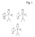
- In the example of Figure 1 wireless terminals establish a communication group. A
user 100 has awireless terminal 300 in his possession. The group has at least two, but preferably several wireless terminals, for example,wireless terminal Wireless terminal 300 may, for example, be a mobile, a Personal Digital Assistant (PDA), a laptop computer, or any other terminal equipped with a short-range radio communication transceiver or low-power radio communication transceiver. An arm 101 (111 and 121 respectively) of user 100 (110 and 120) may be used in group creation to transfer a signal between the users when the users have a physical connection. One of the wireless terminals,e.g. wireless terminal 300 may function as a master that may have administrative tasks in the group creation. Once the group has been established a wireless network or link is used for a wireless group communication between thewireless terminals - In the example of Figure 2 a
physical contact 200 is illustrated.Users physical contact 200 between theusers physical connection 200 preferably allows a signal to transfer between theusers physical contact 200 between, for example,user 100 anduser 120, in which case onlyusers user 110 would be excluded. The signal or signals may also be transmitted viaphysical contact 200 between allusers user 100 tousers user 120 viaphysical contact 200 touser 100.Physical contact 200 may, for example, be a handshake, touching another user's body by touching another user's skin, or any other contact between users where human body can exchange digital information by capacitively coupling small currents (picoampers) through the body.User 100 may holdwireless terminal 300.User 100 can also press an electrode located on the terminal 300 or connected to the terminal (e.g. by wire being a finger sensor that the user can wear on his finger) with his finger to transmit a signal to his body and further to the bodies of the other physically connected users. Respectivelyuser 120 may holdwireless terminal 302 and hold a finger on an electrode or sensor which will receive the signal transmitted from the electrode ofterminal 300. Alternatively theuser 120 may have an electrode or sensor connected to his body (e.g. to his chest) where the electrode is connected by wire toterminal 302. Every user that is to participate in the group to be established should touch the electrode of his terminal at the same time as being in contact with another user so that a signal is transmitted from one terminal (from the electrode) and received at the other terminals (at their respective electrodes) using the users as a signal transfer medium. Thususer 110 would also need to touch the electrode of his terminal to become a member of the group when in physical contact with theother users - In the example of Figure 3, a block diagram of a
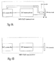
wireless terminal 300 is depicted. The implementation ofwireless terminals Wireless terminal 300 may have a short-range radio communication circuit or transceiver, which here will be called the second circuit. The second circuit is for example a Low Power Radio Frequency (LPRF)transceiver 310 such as a Bluetooth transceiver, utilising anantenna 320, which is connected to thetransceiver 310 for radio transmission of information over a radio link. Additionally the wireless terminal may have another antenna (not shown) that can be used to transmit information relating to other radio communication than short-range radio communication, for example, it may be the antenna for communication over a cellular mobile telephone network. Thereby the wireless group communication could take place over the cellular network or over the short range rf communication. If the frequency of the short range radio communication and of the cellular radio network is the same a common antenna could be used. Acentral controller CC 330 is connected toLP transceiver 310. It may include components that are used to control and operatewireless terminal 300 such as a Central Processor Unit (CPU) 331, aRAM memory 332, input / output (I/O)electronics 333, and be connected to auser interface 334 comprising e.g. a keypad and display. Further aPAN transceiver 340 is connected to theCC 330. In following the PAN transceiver is called a first circuit. In addition to thePAN transceiver 340 the first circuit may include agroup creation electrode 350. ThePAN transceiver 340 may be used to send and receive signals that are transferred through human bodies and possibly throughphysical contact 200.Group creation electrode 350 may be used to couple a surface of human body such as a finger to establish a connection, for example, from a first PAN transceiver (located e.g. inwireless terminal 300 in Fig. 2) and first user's body to second user's body and thereby to a second PAN transceiver (located e.g. inwireless terminal 302 in Fig. 2). A ground or earth may be used to establish a circuit that may enable signal (current) to transfer between the users. The return path, earth/ground, may include conductors and dielectrics in the environment that are in close proximity to the PAN transmitters. The earth ground may be electrically isolated to prevent shorting of the communication circuit. Thewireless terminal 300 preferably also includes a power source such as a chargeable andreleasable battery 370. Theuser interface 334 of thewireless terminal 300 preferably includes control buttons for controlling other functions of the terminal, for example, browsing the menu or selecting icons, as well as a display for display messages and information relating to the establishment of a group as well as relating to a group communication taking place. - In the example of Figure 4A an embodiment of a
PAN transceiver 340 is illustrated. In this example acontroller 342 is connected to atransceiver 343 and to aswitch 344. Thecontroller 342 can trigger thetransceiver 343 to send a signal and it may activate 343 transceiver either to send or receive the signal. Theswitch 344 is used to indicatecontroller 342 to trigger thetransceiver 343 to transmit and receive. Theswitch 344 is connected to anelectrode 350. Theelectrode 350 may shuttle being attached to switch 344. When theelectrode 350 moves over a trigger level of theswitch 344, theswitch 344 indicatescontroller 342 to give a command totransceiver 343 to turn on for transceiving a signal.Switch 344 may have a restoring force such as a spring to set theelectrode 350 to the standby mode when, for example, the user has lifted his finger from theelectrode 350. - In the example of Figure 4B another embodiment of a PAN transceiver 340' is illustrated. In this embodiment a
controller 342 is connected to thetransceiver 343. The controller may settransceiver 343 to send the signal or it may activatetransceiver 343 either to send or receive the signal. In this embodiment anelectrode 350 is connected directly to thetransceiver 343. Theelectrode 350 may also have a connection (not shown) tocontroller 342. The PAN transceiver 340' may now be triggered or activated to transmit a signal that will be conducted to the body of the person via theelectrode 350. The activation can be done by detecting the user touching the electrode, which could be done by e.g. detecting change of capacity at the electrode with thecontroller 342. The signal transmitted from theelectrode 350 is for example a ping signal. The ping signal is preferably a low-frequency signal (less that one megahertz), for example, about 100 - 1000 KHz AC pulse. The length of the signal will be such that it may be transferable and detectable. A low frequency carrier is used so no energy is propagated, minimizing remote eavesdropping and interference by neighboring PANs. - The transmitted ping signal may be used for inquiring or pinging information by transmitting it from a first wireless user terminal to a second wireless user terminal (there can be more users and terminals than just two). The purpose of transmitting the ping signal is to prepare for a second communication so that the second circuit communication, for example a Bluetooth communication, would not require an inquiry or an extra inquiry when initiating the communication. This speeds up the Bluetooth communication and the setting up of the connection does not consume band of the Bluetooth frequency. In the example of Figure 5, the contents of a ping signal is illustrated. The signal includes an identifier of the transmitting transceiver, such as an address of second circuit, for example a
Bluetooth address 501. Typically each Bluetooth transceiver is allocated a unique 48-bit Bluetooth device address (BD_ADDR). The signal may also, though not necessarily, include a clock offset 502. Clock offset 502 is used for synchronization with other units. The signal may also, though not necessarily, include a class ofdevice 503 such as is known from Bluetooth. Class ofdevice 503 may be 24-bit field containing the class of device of the unit that sends the Frequency Hop Synchronization (FHS) packet. Clock offset 502 and Class ofdevices 503 are used to make the communication establishment more efficient. However, they are not necessary for the procedure. - In the example of Figure 6 a flow chart describing the steps of establishing a group is illustrated. The user 100 (for
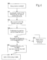
illustrative purposes user 100 and terminal 300 is selected as shown in Figs.1 and 2) may enter a group creation mode at wireless terminal 300 (step 600). Theuser 100 enters the group creation mode by touching or pressing theelectrode 350. Alternatively theuser 100 may enter the group creation mode by selecting the mode from a menu of thewireless terminal 100. Theuser terminal 300 inquires other terminals that may be presence, for example,wireless terminals 301 and 302 (see Fig. 1) that are in the vicinity (step 610). Theuser terminal 300 transmits a message to the terminals that are located within an operation range of the terminal, such asterminals wireless user terminal 300 that transmits the first inquiring message may be termed as a master. Instep 620 themaster terminal 300 receives a reply message from the devices that are able to establish the group and that are located within the range. The master terminal selects at least one of theterminals terminals physical contact 200 of the users (100, 110, 120) and themaster terminal 300 sends a signal such as a ping signal towireless terminals 301 and 302 (step 630). Thephysical contact 200 may be, for example, a handshake, touching by a finger other user's skin, or any kind of contact between users that may provide current (signal) to flow between the bodies of the users. Via the physical contact an electric circuit is completed, allowing pico amp signal to pass from the transmitter of the first circuit of the master user (100) through the body of the master user (100), to the body of the other user(s) (110 and/or 120), and to the receiver of the other user(s) terminal(s) (301 and/or 302), such as toPAN transceiver 340 interminals users electrodes 350 are coupled. A portion of the user's body, for example, a finger should touch thegroup creation electrodes 350 at this point (step 630). This process step may really confirm that there existsphysical contact 200 between the users of the group (or that are to form the group). The user terminals detect the received signal and register it. Themaster terminal 300 sends a query to each wireless terminal(s) (301 and/or 302) to ensure each terminal (that participated in the preparation for establishing a group in step 610) successfully received the ping signal (step 640). If some wireless terminal(s) (301 and/or 302) has not received the ping signal, themaster 300 will send that terminal a request to send the signal (step 650) or to verify that that terminal does not want to participate in the group. If a particular terminal has not responded by sending a message (over the wireless communication) to themaster 300, that terminal is excluded from the group (or could be separately agreed to become a member of the group by a separate wireless communication between the master and that terminal). Themaster 300 may continue the loop ofsteps master 300 has queried all wireless terminals, the group is established using communication over the second circuit (step 660). Themaster 300 informs atstep 670 the other wireless terminals (310 and/or 302) about the successful group creation preferably by use of the second circuit communication. Having established the group the group information is stored in the memory of the central controller CC, such as in a telephone directory like group directory. - In the example of Figure 7, a signalling diagram of an establishment of a group is illustrated. In this example user terminal node 700 (i.e. a first wireless user terminal) transmits a
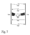
message 720 by use of the second circuit (e.g. Bluetooth) of the terminal. The message includes information about the establishment of the group, and can further include information about the transmitter, protocols, devices, etc. Another user terminal node 710 (i.e. a second wireless user terminal) receives and detects the message likewise by use of the second circuit of the second user terminal. Users then form aphysical contact 200 between each other.User terminal node 710 then sends signal 740 touser terminal node 700 over the establishedphysical contact 200 using the first circuit.User terminal node 700 receives over the physical contact and detects thissignal 740 using the first circuit (e.g. PAN transceiver).User terminal node 710 then transmits amessage 750 touser terminal node 700 to acknowledge the group formation. - In one embodiment the group creation may not require the physical connection of all users at the same time, but in steps. For example, let us assume that wireless terminal (a) will send a ping signal, that will be received at wireless terminals (b) and (d), but not at wireless terminal (c). Next, wireless terminal (c) will send a ping signal that will be received and detected at wireless terminals (b) and (d), but not at wireless terminal (a), so there is missing a direct contact between terminals (a) and (c). However, since there is a connection from wireless terminals (a) and (c) to wireless terminals (b) and (d), there is an indirect connection between (a) and (c) indicating the group establishment. Thus all four terminals (a) - (d) will be forming the group although not all users were in physical contact at the same time, but at different times.
- The order and the amount of the signals and messages may vary. For example, the users may have come in
physical contact 200 with one another, whereby first wireless terminal sends a signal by the first circuit (PAN), and the group may be formed based on the trigger signal sent by the PAN transceiver. Alternatively, the first wireless terminal may send the message by use of the second circuit and the second wireless user terminal receives it over the wireless communication (Bluetooth) and users then establishphysical contact 200 and send the group creation signal to first wireless terminal by the circuit (PAN). The first wireless terminal receives the group creation signal and confirm the establishment of the group by transmitting the confirming message to second wireless terminal by use of the second circuit (Bluetooth). For another example, the first wireless terminal may send the message using the second circuit and a second and a third wireless terminal receive the message and reply to it. The second wireless terminal may now send a signal to first and third wireless terminals via the establishedphysical contact 200 between the users of the wireless terminals. After the signal is sent, the wireless terminals may communicate several messages between themselves using the second circuit and finally the group may be formed and communication may continue. - In the example of Figure 8, the menu at the display of a wireless user terminal is shown when the user selects the group creation mode. The
wireless user terminal 300 preferably has a user interface 334' having a display where the menu is shown to the user. On the display there may, for example, be a text menu where "Form group" command indicates that user wants to create the group. Command "Others" may indicate the selection of some other command than those relating to the group formation, for example, edit short-range network settings. - When "Form group" is selected in the menu and the user presses a select button (a part of user interface 334')
wireless terminal 300 sends the inquiring message and the group establishment continues as described above. - In the example of Figure 9, the information of the terminals that are about to establish the group is shown. In this situation there may be on the display a text "BT1 BT2 BT3" "Establish group?". The text shows the user that
wireless terminals 1, 2, and 3 may form a group. The user acting now as the master may decide whether he wants to establish the group. The user may also decide whether he wants to exclude some terminal from the group. The user of the master terminal may also be allowed to cancel the establishment of the group. - While there has been described what are believed to be the preferred embodiment of the invention, those skilled in the art will recognize that other and further changes and modifications may be made thereto without departing from the scope of the invention.
- For example, the identifier used in the signal may be a phone number or International mobile Equipment Identity (IMEI) and the second circuit and further the second circuit communication in the group may be Global Standard for Mobile / Groupe Speciale Mobile (GSM), General Packet Radio (GPRS) or Universal Mobile Telephone System (UMTS).
Claims (13)
- A method for establishing a group of at least two wireless terminals for wireless group communication between the at least two wireless terminals, comprising the steps of:bringing the users of the at least two wireless terminals into a physical contact;detecting the physical contact between the users of the at least two wireless terminals; andestablishing the group of the at least two wireless terminals for group communication over a wireless link between the at least two wireless terminals of the established group.
- The method of claim 1, further comprising before the step of bringing the users into the physical contact the steps of:wherein the message includes information about the first wireless terminal that initiates the process and about the group creation.entering the at least two wireless terminals into a group creation mode; andinquiring a vicinity of the wireless terminals by transmitting a message from a first wireless terminal of the at least two wireless terminals to a second wireless terminal of the at least two wireless terminals over the wireless communication;
- The method of claim 2, wherein said step of entering the group creation mode comprises the user of the wireless terminal performing an action on the wireless terminal, the action being one of touching an electrode, selecting said group creating mode from a menu of said wireless terminal, and pressing a button.
- The method of claim 1, wherein said step of detecting said physical contact between the users of the at least two wireless terminals comprises the step of:transferring a signal via said physical contact between the users of the wireless terminals.
- The method of claim 4, wherein said step of transferring said signal comprises the steps of:generating said signal in one of the at least two wireless terminals;transmitting said generated signal to the body of a first user, the first user being the user of the signal generating wireless terminal, and further to the body of a second user being physically connected to the first user; anddetecting the transmitted signal in the wireless terminal of the second user.
- The method of claim 4, wherein said signal includes one of
a low-frequency signal;
a signal the frequency of which is less than 1 megahertz; and
a signal comprising at least an address of the transmitting wireless terminal, and optionally at least one of clock offset information, and class of device. - The method of claim 1, wherein said step of establishing said group of the physically connected users of the at least two wireless terminals comprises the step of:confirming the establishment of said group between the users of the wireless terminals by transmitting a message to a wireless terminal of the group over the wireless communication.
- The method of claim 1, wherein each wireless terminal comprises a low power radio transceiver for the wireless communication, an antenna, a PAN transceiver and a contact electrode for generating and transmitting said signal into a body of the user.
- The method of claim 1, wherein said group comprises at least three wireless user terminals; and
wherein said physical contact is a chain contact where one of the users is physically connected to a second one of the users further being in physical contact with a third one of said users; and
wherein each of the users of the group are in physical contact with each other upon forming the group; and
wherein while the users are in the physical contact, each user is also in contact with an electrode further having a connection with the wireless terminal of each respective user. - A wireless communication terminal for group communication with at least one other wireless terminal, comprising:a detecting element for detecting the physical contact between the user of the wireless terminal and the user of the at least one other wireless terminal;means for participating in the establishment of the group of the wireless terminal and the at least one other wireless terminal for group communication over a wireless link with the at least one other wireless terminal of the established group; anda transceiver for performing wireless group communication involving the wireless terminal and the at least one other wireless terminal of the established group.
- The wireless communication terminal of claim 10, wherein said transceiver comprises a short-range radio transceiver and an antenna; and
wherein said detecting element comprises a PAN transceiver, an electrode for contacting the body of the user, and a switch to trigger transmission of a signal to the body of the user when in said physical contact. - The terminal of claim 10, wherein said physical contact includes one of a handshake, any contact between the users enabling a small electrical current to flow from a first body of a first user to a second body of a second user, and any contact wherein bodies can exchange digital information coupling capacitively small currents through said body.
- The terminal of claim 11, wherein said signal includes one of a low-frequency signal, and a signal the signal frequency of which includes about 100 - 1000 KHz.
Applications Claiming Priority (2)
| Application Number | Priority Date | Filing Date | Title |
|---|---|---|---|
| FI20002861 | 2000-12-27 | ||
| FI20002861A FI110560B (en) | 2000-12-27 | 2000-12-27 | Grouping of wireless communication terminals |
Publications (3)
| Publication Number | Publication Date |
|---|---|
| EP1220501A2 true EP1220501A2 (en) | 2002-07-03 |
| EP1220501A3 EP1220501A3 (en) | 2003-12-17 |
| EP1220501B1 EP1220501B1 (en) | 2008-07-23 |
Family
ID=8559819
Family Applications (1)
| Application Number | Title | Priority Date | Filing Date |
|---|---|---|---|
| EP01660224A Expired - Lifetime EP1220501B1 (en) | 2000-12-27 | 2001-12-07 | Group creation for wireless communication terminals |
Country Status (5)
| Country | Link |
|---|---|
| US (1) | US7082316B2 (en) |
| EP (1) | EP1220501B1 (en) |
| JP (1) | JP4065379B2 (en) |
| DE (1) | DE60134946D1 (en) |
| FI (1) | FI110560B (en) |
Cited By (23)
| Publication number | Priority date | Publication date | Assignee | Title |
|---|---|---|---|---|
| WO2004082212A2 (en) | 2003-03-14 | 2004-09-23 | Nokia Corporation | Method for initiating a wireless transfer of data between at least two electronic devices, electronic device and software program therefor |
| FR2860668A1 (en) * | 2003-10-06 | 2005-04-08 | Valeo Securite Habitacle | CURRENT BAUDGE IDENTIFICATION SYSTEM CIRCULATING THROUGH THE BODY TO TWO DETECTION MODES |
| WO2006087670A1 (en) | 2005-02-17 | 2006-08-24 | Koninklijke Philips Electronics N.V. | Device capable of being operated within a network, network system, method of operating a device within a network, program element, and computer-readable medium |
| WO2007084807A1 (en) | 2006-01-18 | 2007-07-26 | Koninklijke Philips Electronics, N.V. | Automatic and secure configuration of wireless medical networks |
| WO2007096810A1 (en) | 2006-02-24 | 2007-08-30 | Koninklijke Philips Electronics N.V. | Wireless body sensor network |
| WO2008015627A1 (en) * | 2006-07-31 | 2008-02-07 | Koninklijke Philips Electronics N.V. | Method and system for configuring a network and network management device |
| WO2009081337A1 (en) * | 2007-12-20 | 2009-07-02 | Philips Intellectual Property & Standards Gmbh | Switching between multiple coupling modes |
| WO2009112897A1 (en) * | 2008-03-13 | 2009-09-17 | Sony Ericsson Mobile Communications Ab | Skin-based information transfer between mobile devices |
| WO2010073180A1 (en) * | 2008-12-23 | 2010-07-01 | Koninklijke Philips Electronics N.V. | Combining body-coupled communication and radio frequency communication |
| WO2011155996A2 (en) * | 2010-06-09 | 2011-12-15 | Maxx Wireless, Incorporated | Group messaging integration system, method and apparatus |
| EP2413523A1 (en) * | 2010-07-30 | 2012-02-01 | Pantech Co., Ltd. | Device and Method for Human Body Communication Network System |
| US8639819B2 (en) | 2004-02-05 | 2014-01-28 | Nokia Corporation | Ad-hoc connection between electronic devices |
| WO2016030769A1 (en) * | 2014-08-27 | 2016-03-03 | Sony Corporation | A system, an object and a method for grouping of objects in a body area network |
| US9332377B2 (en) | 2013-12-05 | 2016-05-03 | Sony Corporation | Device and method for control of data transfer in local area network |
| US9351100B2 (en) | 2013-12-05 | 2016-05-24 | Sony Corporation | Device for control of data transfer in local area network |
| EP2939222A4 (en) * | 2012-12-28 | 2016-06-22 | Joseph Nicholi Prencipe | Contact information social exchange method and system |
| US9489511B2 (en) | 2013-12-05 | 2016-11-08 | Sony Corporation | Wearable device and a method for storing credentials associated with an electronic device in said wearable device |
| US9674883B2 (en) | 2014-07-23 | 2017-06-06 | Sony Mobile Communications Inc. | System, an object and a method for grouping of objects in a body area network |
| EP3241361A1 (en) * | 2014-12-30 | 2017-11-08 | General Electric Company | Method and system for verifying wireless connection between medical devices |
| US9826561B2 (en) | 2013-12-05 | 2017-11-21 | Sony Corporation | System and method for allowing access to electronic devices using a body area network |
| US9842329B2 (en) | 2015-02-13 | 2017-12-12 | Sony Corporation | Body area network for secure payment |
| US20180124128A1 (en) * | 2016-10-31 | 2018-05-03 | Microsoft Technology Licensing, Llc | Enhanced techniques for joining teleconferencing sessions |
| US10085129B2 (en) | 2007-11-30 | 2018-09-25 | Microsoft Technology Licensing, Llc | Mobile device communication |
Families Citing this family (157)
| Publication number | Priority date | Publication date | Assignee | Title |
|---|---|---|---|---|
| US9269511B2 (en) * | 2001-06-29 | 2016-02-23 | Peter Ar-Fu Lam | Hand controlled electronics toy article |
| JP4215968B2 (en) * | 2001-07-10 | 2009-01-28 | シャープ株式会社 | Communication system, terminal used in the communication system, communication method in the terminal, and program for communication in the terminal |
| US7305700B2 (en) | 2002-01-08 | 2007-12-04 | Seven Networks, Inc. | Secure transport for mobile communication network |
| US20030162556A1 (en) * | 2002-02-28 | 2003-08-28 | Libes Michael A. | Method and system for communication between two wireless-enabled devices |
| US8224985B2 (en) | 2005-10-04 | 2012-07-17 | Sony Computer Entertainment Inc. | Peer-to-peer communication traversing symmetric network address translators |
| US8060626B2 (en) * | 2008-09-22 | 2011-11-15 | Sony Computer Entertainment America Llc. | Method for host selection based on discovered NAT type |
| US8468126B2 (en) | 2005-08-01 | 2013-06-18 | Seven Networks, Inc. | Publishing data in an information community |
| US7853563B2 (en) | 2005-08-01 | 2010-12-14 | Seven Networks, Inc. | Universal data aggregation |
| US7917468B2 (en) | 2005-08-01 | 2011-03-29 | Seven Networks, Inc. | Linking of personal information management data |
| JP4156531B2 (en) * | 2003-02-03 | 2008-09-24 | 富士フイルム株式会社 | Communication equipment |
| US20040242266A1 (en) * | 2003-05-29 | 2004-12-02 | Roberto Tagliabue | Apparatus and method for communication of visual messages |
| US20040242210A1 (en) * | 2003-05-29 | 2004-12-02 | Roberto Tagliabue | System and method for communication of visual messages |
| ATE423364T1 (en) * | 2003-12-18 | 2009-03-15 | Gemalto Sa | SYSTEM FOR IDENTIFYING AN INDIVIDUAL IN AN ELECTRONIC TRANSACTION |
| US7769409B2 (en) * | 2004-06-23 | 2010-08-03 | Sony Computer Entertainment America Inc. | Network participant status evaluation |
| US20060073856A1 (en) * | 2004-09-09 | 2006-04-06 | Lundberg Steven W | Remoted vibrating element for a mobile phone |
| DE102004047759B3 (en) * | 2004-09-30 | 2006-06-01 | Siemens Audiologische Technik Gmbh | Use of a hearing aid system with at least two hearing aids |
| JP4292212B2 (en) * | 2004-10-05 | 2009-07-08 | 高陽 関根 | Work state detection device |
| US8010082B2 (en) | 2004-10-20 | 2011-08-30 | Seven Networks, Inc. | Flexible billing architecture |
| US7441271B2 (en) | 2004-10-20 | 2008-10-21 | Seven Networks | Method and apparatus for intercepting events in a communication system |
| US7706781B2 (en) | 2004-11-22 | 2010-04-27 | Seven Networks International Oy | Data security in a mobile e-mail service |
| US9913300B2 (en) | 2011-12-14 | 2018-03-06 | Kodiak Networks, Inc. | Push-to-talk-over-cellular (PoC) |
| US10057105B2 (en) | 2004-11-23 | 2018-08-21 | Kodiak Networks, Inc. | Architecture framework to realize push-to-X services using cloudbased storage services |
| US10367863B2 (en) | 2004-11-23 | 2019-07-30 | Kodiak Networks Inc. | Method for providing dynamic quality of service for push-to-talk service |
| US9485787B2 (en) | 2005-05-24 | 2016-11-01 | Kodiak Networks, Inc. | Method to achieve a fully acknowledged mode communication (FAMC) in push-to-talk-over-cellular (PoC) |
| US10111055B2 (en) | 2004-11-23 | 2018-10-23 | Kodiak Networks, Inc. | Optimized methods for large group calling using unicast and multicast transport bearer for PoC |
| US10178513B2 (en) | 2004-11-23 | 2019-01-08 | Kodiak Networks, Inc. | Relay-mode and direct-mode operations for push-to-talk-over-cellular (PoC) using WiFi-technologies |
| US10750327B2 (en) | 2004-11-23 | 2020-08-18 | Kodiak Networks Inc | Method for multiplexing media streams to optimize network resource usage for push-to-talk-over-cellular service |
| US9137646B2 (en) | 2004-11-23 | 2015-09-15 | Kodiak Networks, Inc. | Method and framework to detect service users in an insufficient wireless radio coverage network and to improve a service delivery experience by guaranteed presence |
| US10116691B2 (en) | 2004-11-23 | 2018-10-30 | Kodiak Networks, Inc. | VoIP denial-of-service protection mechanisms from attack |
| FI117152B (en) | 2004-12-03 | 2006-06-30 | Seven Networks Internat Oy | E-mail service provisioning method for mobile terminal, involves using domain part and further parameters to generate new parameter set in list of setting parameter sets, if provisioning of e-mail service is successful |
| US20060136015A1 (en) * | 2004-12-08 | 2006-06-22 | Duck-Gun Park | Human body communication device, human body communication system and method using the same |
| US7877703B1 (en) | 2005-03-14 | 2011-01-25 | Seven Networks, Inc. | Intelligent rendering of information in a limited display environment |
| JP4586618B2 (en) | 2005-04-18 | 2010-11-24 | ソニー株式会社 | Human body communication system and communication apparatus |
| US7796742B1 (en) | 2005-04-21 | 2010-09-14 | Seven Networks, Inc. | Systems and methods for simplified provisioning |
| US7684815B2 (en) * | 2005-04-21 | 2010-03-23 | Microsoft Corporation | Implicit group formation around feed content for mobile devices |
| US8438633B1 (en) | 2005-04-21 | 2013-05-07 | Seven Networks, Inc. | Flexible real-time inbox access |
| ATE464702T1 (en) | 2005-04-25 | 2010-04-15 | Sony Ericsson Mobile Comm Ab | ELECTRONIC DEVICE FOR A WIRELESS COMMUNICATIONS SYSTEM AND METHOD FOR OPERATING AN ELECTRONIC DEVICE FOR A WIRELESS COMMUNICATIONS SYSTEM |
| US20060282332A1 (en) * | 2005-04-28 | 2006-12-14 | Pfleging Gerald W | Method for transmitting a wireless receipt to a personal digital device |
| US7577459B2 (en) * | 2005-05-11 | 2009-08-18 | Nokia Corporation | Establishing a communication link |
| US7865140B2 (en) * | 2005-06-14 | 2011-01-04 | The Invention Science Fund I, Llc | Device pairing via intermediary device |
| US9743266B2 (en) | 2005-05-23 | 2017-08-22 | Invention Science Fund I, Llc | Device pairing via device to device contact |
| WO2006136660A1 (en) | 2005-06-21 | 2006-12-28 | Seven Networks International Oy | Maintaining an ip connection in a mobile network |
| US8069166B2 (en) | 2005-08-01 | 2011-11-29 | Seven Networks, Inc. | Managing user-to-user contact with inferred presence information |
| KR100723307B1 (en) * | 2005-10-25 | 2007-05-30 | 한국전자통신연구원 | Communication device |
| KR100785769B1 (en) * | 2005-12-08 | 2007-12-18 | 한국전자통신연구원 | Communication apparatus using frequency according to security and transmission distance |
| KR100772525B1 (en) * | 2005-12-08 | 2007-11-01 | 한국전자통신연구원 | apparatus and method for providing service based on touch and play, and the system using the same |
| US7525425B2 (en) * | 2006-01-20 | 2009-04-28 | Perdiem Llc | System and method for defining an event based on relationship between an object location and a user-defined zone |
| US7769395B2 (en) | 2006-06-20 | 2010-08-03 | Seven Networks, Inc. | Location-based operations and messaging |
| WO2007129237A1 (en) * | 2006-05-08 | 2007-11-15 | Koninklijke Philips Electronics N.V. | Method of transferring application data from a first device to a second device, and a data transfer system |
| US20080120555A1 (en) * | 2006-11-21 | 2008-05-22 | Intermec Ip Corp. | Wireless device grouping via common attribute |
| KR20080052373A (en) * | 2006-12-06 | 2008-06-11 | 한국전자통신연구원 | Apparatus and method for providing media advertisement service using human body telecommunication |
| US7782890B2 (en) * | 2006-12-22 | 2010-08-24 | Magix Ag | System and method for dynamic mobile communication |
| JP5273871B2 (en) * | 2007-02-14 | 2013-08-28 | カバ・アクチェンゲゼルシャフト | System and portable device for transmission of identification signals |
| US7995478B2 (en) * | 2007-05-30 | 2011-08-09 | Sony Computer Entertainment Inc. | Network communication with path MTU size discovery |
| US8805425B2 (en) | 2007-06-01 | 2014-08-12 | Seven Networks, Inc. | Integrated messaging |
| US8693494B2 (en) | 2007-06-01 | 2014-04-08 | Seven Networks, Inc. | Polling |
| WO2008151624A1 (en) * | 2007-06-13 | 2008-12-18 | Widex A/S | Hearing aid system establishing a conversation group among hearing aids used by different users |
| EP2153692B1 (en) * | 2007-06-13 | 2010-12-08 | Widex A/S | A system and a method for establishing a conversation group among a number of hearing aids |
| US7908393B2 (en) * | 2007-12-04 | 2011-03-15 | Sony Computer Entertainment Inc. | Network bandwidth detection, distribution and traffic prioritization |
| US8364181B2 (en) | 2007-12-10 | 2013-01-29 | Seven Networks, Inc. | Electronic-mail filtering for mobile devices |
| US9002828B2 (en) | 2007-12-13 | 2015-04-07 | Seven Networks, Inc. | Predictive content delivery |
| US8793305B2 (en) | 2007-12-13 | 2014-07-29 | Seven Networks, Inc. | Content delivery to a mobile device from a content service |
| US8421748B2 (en) * | 2007-12-21 | 2013-04-16 | Rohm Co., Ltd. | Information exchange device |
| US8107921B2 (en) | 2008-01-11 | 2012-01-31 | Seven Networks, Inc. | Mobile virtual network operator |
| US8862657B2 (en) | 2008-01-25 | 2014-10-14 | Seven Networks, Inc. | Policy based content service |
| US20090193338A1 (en) | 2008-01-28 | 2009-07-30 | Trevor Fiatal | Reducing network and battery consumption during content delivery and playback |
| WO2009105115A2 (en) * | 2008-02-22 | 2009-08-27 | T-Mobile Usa, Inc. | Data exchange initiated by tapping devices |
| US7856506B2 (en) | 2008-03-05 | 2010-12-21 | Sony Computer Entertainment Inc. | Traversal of symmetric network address translator for multiple simultaneous connections |
| JP4666319B2 (en) * | 2008-03-31 | 2011-04-06 | Necシステムテクノロジー株式会社 | Biological wearable data communication device |
| JP5131016B2 (en) * | 2008-04-30 | 2013-01-30 | 富士通株式会社 | Wireless communication apparatus and communication control method |
| US8179232B2 (en) * | 2008-05-05 | 2012-05-15 | Round Rock Research, Llc | RFID interrogator with adjustable signal characteristics |
| US8787947B2 (en) | 2008-06-18 | 2014-07-22 | Seven Networks, Inc. | Application discovery on mobile devices |
| US8078158B2 (en) | 2008-06-26 | 2011-12-13 | Seven Networks, Inc. | Provisioning applications for a mobile device |
| US8255533B2 (en) * | 2008-06-30 | 2012-08-28 | Panasonic Corporation | Wireless communication system, communication terminal, management terminal, communication method, and integrated circuit |
| US8909759B2 (en) | 2008-10-10 | 2014-12-09 | Seven Networks, Inc. | Bandwidth measurement |
| US8624836B1 (en) | 2008-10-24 | 2014-01-07 | Google Inc. | Gesture-based small device input |
| KR101582686B1 (en) * | 2009-03-02 | 2016-01-05 | 엘지전자 주식회사 | Method for displaying items and mobile terminal using the same |
| WO2010117815A1 (en) * | 2009-03-30 | 2010-10-14 | Kodiak Networks, Inc. | Enhanced group calling features for connected portfolio services in a wireless communications network |
| JP5195637B2 (en) * | 2009-05-21 | 2013-05-08 | 富士通株式会社 | BAN sensor wireless communication apparatus and method |
| KR20100126958A (en) * | 2009-05-25 | 2010-12-03 | 삼성전자주식회사 | Apparatus and method for contrlling multi-device |
| US20100321159A1 (en) * | 2009-06-18 | 2010-12-23 | Authentec, Inc. | Touch based data communication using biometric finger sensor and associated methods |
| WO2011021531A1 (en) | 2009-08-18 | 2011-02-24 | ローム株式会社 | Input/output device, mobile device, and information displaying device |
| JP2011128809A (en) * | 2009-12-16 | 2011-06-30 | Rohm Co Ltd | Information input/output device |
| JP2013009019A (en) * | 2009-10-07 | 2013-01-10 | Ad-Sol Nissin Corp | Data communication system |
| US8666812B1 (en) * | 2009-11-10 | 2014-03-04 | Google Inc. | Distributing content based on transaction information |
| US9043731B2 (en) | 2010-03-30 | 2015-05-26 | Seven Networks, Inc. | 3D mobile user interface with configurable workspace management |
| US9077630B2 (en) | 2010-07-26 | 2015-07-07 | Seven Networks, Inc. | Distributed implementation of dynamic wireless traffic policy |
| US8838783B2 (en) | 2010-07-26 | 2014-09-16 | Seven Networks, Inc. | Distributed caching for resource and mobile network traffic management |
| JP5676762B2 (en) | 2010-07-26 | 2015-02-25 | セブン ネットワークス インコーポレイテッド | Mobile application traffic optimization |
| US9043433B2 (en) | 2010-07-26 | 2015-05-26 | Seven Networks, Inc. | Mobile network traffic coordination across multiple applications |
| KR101261687B1 (en) * | 2010-08-09 | 2013-05-06 | 주식회사 팬택 | Broadcasting System and Method for using human body communication |
| US8166164B1 (en) | 2010-11-01 | 2012-04-24 | Seven Networks, Inc. | Application and network-based long poll request detection and cacheability assessment therefor |
| US8484314B2 (en) | 2010-11-01 | 2013-07-09 | Seven Networks, Inc. | Distributed caching in a wireless network of content delivered for a mobile application over a long-held request |
| US9060032B2 (en) | 2010-11-01 | 2015-06-16 | Seven Networks, Inc. | Selective data compression by a distributed traffic management system to reduce mobile data traffic and signaling traffic |
| WO2012061430A2 (en) | 2010-11-01 | 2012-05-10 | Michael Luna | Distributed management of keep-alive message signaling for mobile network resource conservation and optimization |
| WO2012060995A2 (en) | 2010-11-01 | 2012-05-10 | Michael Luna | Distributed caching in a wireless network of content delivered for a mobile application over a long-held request |
| US8843153B2 (en) | 2010-11-01 | 2014-09-23 | Seven Networks, Inc. | Mobile traffic categorization and policy for network use optimization while preserving user experience |
| US8204953B2 (en) | 2010-11-01 | 2012-06-19 | Seven Networks, Inc. | Distributed system for cache defeat detection and caching of content addressed by identifiers intended to defeat cache |
| WO2012060996A2 (en) | 2010-11-01 | 2012-05-10 | Michael Luna | Caching adapted for mobile application behavior and network conditions |
| US9330196B2 (en) | 2010-11-01 | 2016-05-03 | Seven Networks, Llc | Wireless traffic management system cache optimization using http headers |
| EP2636268B1 (en) | 2010-11-22 | 2019-02-27 | Seven Networks, LLC | Optimization of resource polling intervals to satisfy mobile device requests |
| CN103404193B (en) | 2010-11-22 | 2018-06-05 | 七网络有限责任公司 | The connection that adjustment data transmission is established with the transmission being optimized for through wireless network |
| KR101330262B1 (en) * | 2010-12-14 | 2013-11-15 | 주식회사 팬택 | Terminal apparatus and method for human body communication capable of data change |
| EP2661697B1 (en) | 2011-01-07 | 2018-11-21 | Seven Networks, LLC | System and method for reduction of mobile network traffic used for domain name system (dns) queries |
| US20120189140A1 (en) * | 2011-01-21 | 2012-07-26 | Apple Inc. | Audio-sharing network |
| US20130013697A1 (en) * | 2011-02-14 | 2013-01-10 | Yasuhiro Tsuchida | Group generation device |
| US9084105B2 (en) | 2011-04-19 | 2015-07-14 | Seven Networks, Inc. | Device resources sharing for network resource conservation |
| EP2621144B1 (en) | 2011-04-27 | 2014-06-25 | Seven Networks, Inc. | System and method for making requests on behalf of a mobile device based on atomic processes for mobile network traffic relief |
| EP2702500B1 (en) | 2011-04-27 | 2017-07-19 | Seven Networks, LLC | Detecting and preserving state for satisfying application requests in a distributed proxy and cache system |
| JP5936024B2 (en) * | 2011-06-07 | 2016-06-15 | 国立大学法人 筑波大学 | Biological contact data measuring device, biological contact data measuring system, and biological contact data measuring method |
| US9239800B2 (en) | 2011-07-27 | 2016-01-19 | Seven Networks, Llc | Automatic generation and distribution of policy information regarding malicious mobile traffic in a wireless network |
| US8736878B2 (en) | 2011-11-23 | 2014-05-27 | Canon U.S.A., Inc. | System and method for obtaining an electronic document |
| WO2013086214A1 (en) | 2011-12-06 | 2013-06-13 | Seven Networks, Inc. | A system of redundantly clustered machines to provide failover mechanisms for mobile traffic management and network resource conservation |
| US8918503B2 (en) | 2011-12-06 | 2014-12-23 | Seven Networks, Inc. | Optimization of mobile traffic directed to private networks and operator configurability thereof |
| WO2013086447A1 (en) | 2011-12-07 | 2013-06-13 | Seven Networks, Inc. | Radio-awareness of mobile device for sending server-side control signals using a wireless network optimized transport protocol |
| EP2788889A4 (en) | 2011-12-07 | 2015-08-12 | Seven Networks Inc | Flexible and dynamic integration schemas of a traffic management system with various network operators for network traffic alleviation |
| WO2013090212A1 (en) | 2011-12-14 | 2013-06-20 | Seven Networks, Inc. | Mobile network reporting and usage analytics system and method using aggregation of data in a distributed traffic optimization system |
| WO2013090834A1 (en) | 2011-12-14 | 2013-06-20 | Seven Networks, Inc. | Operation modes for mobile traffic optimization and concurrent management of optimized and non-optimized traffic |
| US8861354B2 (en) | 2011-12-14 | 2014-10-14 | Seven Networks, Inc. | Hierarchies and categories for management and deployment of policies for distributed wireless traffic optimization |
| EP2801236A4 (en) | 2012-01-05 | 2015-10-21 | Seven Networks Inc | Detection and management of user interactions with foreground applications on a mobile device in distributed caching |
| CA2804368C (en) | 2012-02-01 | 2018-03-13 | Kodiak Networks, Inc. | Wifi interworking solutions for push-to-talk-over-cellular (poc) |
| US9203864B2 (en) | 2012-02-02 | 2015-12-01 | Seven Networks, Llc | Dynamic categorization of applications for network access in a mobile network |
| WO2013116852A1 (en) | 2012-02-03 | 2013-08-08 | Seven Networks, Inc. | User as an end point for profiling and optimizing the delivery of content and data in a wireless network |
| US8812695B2 (en) | 2012-04-09 | 2014-08-19 | Seven Networks, Inc. | Method and system for management of a virtual network connection without heartbeat messages |
| WO2013155208A1 (en) | 2012-04-10 | 2013-10-17 | Seven Networks, Inc. | Intelligent customer service/call center services enhanced using real-time and historical mobile application and traffic-related statistics collected by a distributed caching system in a mobile network |
| WO2014011216A1 (en) | 2012-07-13 | 2014-01-16 | Seven Networks, Inc. | Dynamic bandwidth adjustment for browsing or streaming activity in a wireless network based on prediction of user behavior when interacting with mobile applications |
| US9369606B2 (en) | 2012-09-12 | 2016-06-14 | Xerox Corporation | Automated pairing of multifunction devices and external devices |
| US9161258B2 (en) | 2012-10-24 | 2015-10-13 | Seven Networks, Llc | Optimized and selective management of policy deployment to mobile clients in a congested network to prevent further aggravation of network congestion |
| US9307493B2 (en) | 2012-12-20 | 2016-04-05 | Seven Networks, Llc | Systems and methods for application management of mobile device radio state promotion and demotion |
| US9241314B2 (en) | 2013-01-23 | 2016-01-19 | Seven Networks, Llc | Mobile device with application or context aware fast dormancy |
| US8874761B2 (en) | 2013-01-25 | 2014-10-28 | Seven Networks, Inc. | Signaling optimization in a wireless network for traffic utilizing proprietary and non-proprietary protocols |
| US9326185B2 (en) | 2013-03-11 | 2016-04-26 | Seven Networks, Llc | Mobile network congestion recognition for optimization of mobile traffic |
| EP2811770A1 (en) * | 2013-06-07 | 2014-12-10 | Gemalto SA | Pairing device |
| KR102166719B1 (en) | 2013-06-27 | 2020-10-16 | 삼성전자주식회사 | Apparatus and method for information exchange |
| EP3014916A1 (en) * | 2013-06-28 | 2016-05-04 | Nec Corporation | Secure group creation in proximity based service communication |
| US9065765B2 (en) | 2013-07-22 | 2015-06-23 | Seven Networks, Inc. | Proxy server associated with a mobile carrier for enhancing mobile traffic management in a mobile network |
| CA2921531C (en) | 2013-07-23 | 2018-02-27 | Kodiak Networks, Inc. | Radio access network (ran) aware service delivery for push-to-talk-over-cellular (poc) networks |
| CN104919392B (en) * | 2013-08-14 | 2018-02-13 | 宇龙计算机通信科技(深圳)有限公司 | Wearable device and data transmission method |
| CN103809750A (en) * | 2014-02-08 | 2014-05-21 | 北京智谷睿拓技术服务有限公司 | Information interaction method based on wearable device and wearable device |
| US9667353B2 (en) * | 2014-07-11 | 2017-05-30 | Sony Corporation | Methods of providing body area network communications when a user touches a button of a wireless electronic device, and related wireless electronic devices and wearable wireless electronic devices |
| US10362074B2 (en) | 2015-02-03 | 2019-07-23 | Kodiak Networks, Inc | Session management and notification mechanisms for push-to-talk (PTT) |
| EP3292485B1 (en) | 2015-05-07 | 2021-02-17 | Kodiak Networks, Inc. | System and method for data synchronization |
| WO2017062627A1 (en) | 2015-10-06 | 2017-04-13 | Kodiak Networks, Inc. | System and method for improved push-to-talk communication performance |
| AU2016336443B2 (en) | 2015-10-06 | 2019-11-14 | Kodiak Networks, Inc. | PTT network with radio condition aware media packet aggregation scheme |
| GB2561722B (en) | 2015-10-23 | 2021-10-20 | Kodiak Networks Inc | System and method for content messaging |
| US10838502B2 (en) * | 2016-03-29 | 2020-11-17 | Microsoft Technology Licensing, Llc | Sharing across environments |
| DE112017002108T5 (en) | 2016-04-22 | 2019-01-03 | Kodiak Networks Inc. | SYSTEM AND METHOD FOR PUSH-TO-TALK (PTT) ON-BUTTON PRESSURE CALL |
| US10555370B2 (en) | 2016-09-28 | 2020-02-04 | Kodiak Networks, Inc. | System and method for push-to-talk (PTT) in high latency networks |
| US10257669B2 (en) | 2016-12-01 | 2019-04-09 | Kodiak Networks, Inc. | PTX data analytic engine notifying group list of detected risk event |
| US10630529B2 (en) | 2016-12-29 | 2020-04-21 | Kodiak Networks, Inc. | System and method for push-to-talk (PTT) in mobile edge computing (MEC) |
| US10341823B2 (en) | 2016-12-30 | 2019-07-02 | Kodiak Networks Inc. | System and method for direct mode push to talk communication protocols |
| CN109618406B (en) * | 2019-03-01 | 2019-07-05 | 展讯通信(上海)有限公司 | Wireless connection method, equipment group, system |
| US11546391B2 (en) | 2019-11-01 | 2023-01-03 | Microsoft Technology Licensing, Llc | Teleconferencing interfaces and controls for paired user computing devices |
| US11304246B2 (en) | 2019-11-01 | 2022-04-12 | Microsoft Technology Licensing, Llc | Proximity-based pairing and operation of user-specific companion devices |
| US11256392B2 (en) | 2019-11-01 | 2022-02-22 | Microsoft Technology Licensing, Llc | Unified interfaces for paired user computing devices |
| US11184742B2 (en) * | 2020-04-20 | 2021-11-23 | Motorola Solutions, Inc. | Method and apparatus for determining an approver for requesting permission to join a dynamically-created talkgroup |
| US10999227B1 (en) * | 2020-07-06 | 2021-05-04 | TraDove, Inc. | Systems and methods for electronic group exchange of digital business cards during video conference, teleconference or meeting at social distance |
Citations (4)
| Publication number | Priority date | Publication date | Assignee | Title |
|---|---|---|---|---|
| GB2306725A (en) * | 1995-10-17 | 1997-05-07 | Alan William Robinson | Personnel identification system |
| WO2000030374A2 (en) * | 1998-11-18 | 2000-05-25 | Nokia Corporation | A group communication device and method |
| EP1024626A1 (en) * | 1999-01-27 | 2000-08-02 | International Business Machines Corporation | Method, apparatus, and communication system for exchange of information in pervasive environments |
| US6128381A (en) * | 1996-12-27 | 2000-10-03 | Telefonaktiebolaget Lm Ericsson | Mobile communication unit |
Family Cites Families (12)
| Publication number | Priority date | Publication date | Assignee | Title |
|---|---|---|---|---|
| US5471646A (en) * | 1994-08-01 | 1995-11-28 | Motorola, Inc. | Method for establishing a user defined radio talk group in a trunked radio communication system |
| US5511232A (en) * | 1994-12-02 | 1996-04-23 | Motorola, Inc. | Method for providing autonomous radio talk group configuration |
| US5796827A (en) * | 1996-11-14 | 1998-08-18 | International Business Machines Corporation | System and method for near-field human-body coupling for encrypted communication with identification cards |
| US6223018B1 (en) * | 1996-12-12 | 2001-04-24 | Nippon Telegraph And Telephone Corporation | Intra-body information transfer device |
| CN1259249A (en) | 1997-06-02 | 2000-07-05 | 摩托罗拉公司 | Method for authorizing couplings between devices in a capability addressable network |
| US6104913A (en) * | 1998-03-11 | 2000-08-15 | Bell Atlantic Network Services, Inc. | Personal area network for personal telephone services |
| US6542717B1 (en) * | 1999-01-20 | 2003-04-01 | International Business Machines Corporation | System and method for optimizing personal area network (PAN) electrostatic communication |
| US6275500B1 (en) * | 1999-08-09 | 2001-08-14 | Motorola, Inc. | Method and apparatus for dynamic control of talk groups in a wireless network |
| US6347095B1 (en) * | 1999-11-15 | 2002-02-12 | Pango Networks, Inc. | System, devices and methods for use in proximity-based networking |
| JP2001144661A (en) * | 1999-11-17 | 2001-05-25 | Sony Corp | Data transmitter and data receiver |
| US6430395B2 (en) * | 2000-04-07 | 2002-08-06 | Commil Ltd. | Wireless private branch exchange (WPBX) and communicating between mobile units and base stations |
| JP2001344352A (en) * | 2000-05-31 | 2001-12-14 | Toshiba Corp | Life assisting device, life assisting method and advertisement information providing method |
-
2000
- 2000-12-27 FI FI20002861A patent/FI110560B/en not_active IP Right Cessation
-
2001
- 2001-12-07 EP EP01660224A patent/EP1220501B1/en not_active Expired - Lifetime
- 2001-12-07 DE DE60134946T patent/DE60134946D1/en not_active Expired - Lifetime
- 2001-12-20 US US10/027,501 patent/US7082316B2/en not_active Expired - Lifetime
- 2001-12-27 JP JP2001396674A patent/JP4065379B2/en not_active Expired - Fee Related
Patent Citations (4)
| Publication number | Priority date | Publication date | Assignee | Title |
|---|---|---|---|---|
| GB2306725A (en) * | 1995-10-17 | 1997-05-07 | Alan William Robinson | Personnel identification system |
| US6128381A (en) * | 1996-12-27 | 2000-10-03 | Telefonaktiebolaget Lm Ericsson | Mobile communication unit |
| WO2000030374A2 (en) * | 1998-11-18 | 2000-05-25 | Nokia Corporation | A group communication device and method |
| EP1024626A1 (en) * | 1999-01-27 | 2000-08-02 | International Business Machines Corporation | Method, apparatus, and communication system for exchange of information in pervasive environments |
Non-Patent Citations (2)
| Title |
|---|
| HAARTSEN J C MATTISSON S: "Bluetooth - A new low-power radio interface providing short-range connectivity" PROCEEDINGS OF THE IEEE, IEEE. NEW YORK, US, vol. 88, no. 10, October 2000 (2000-10), pages 1651-1661, XP002958459 ISSN: 0018-9219 * |
| ZIMMERMAN T G: "PERSONAL AREA NETWORKS: NEAR-FIELD INTRABODY COMMUNICATION" IBM SYSTEMS JOURNAL, IBM CORP. ARMONK, NEW YORK, US, vol. 35, no. 3/4, 1996, pages 609-617, XP000635090 ISSN: 0018-8670 * |
Cited By (50)
| Publication number | Priority date | Publication date | Assignee | Title |
|---|---|---|---|---|
| WO2004082212A3 (en) * | 2003-03-14 | 2006-03-02 | Nokia Corp | Method for initiating a wireless transfer of data between at least two electronic devices, electronic device and software program therefor |
| US8165523B2 (en) | 2003-03-14 | 2012-04-24 | Nokia Corporation | Method for initiating a wireless transfer of data between at least two electronic devices, electronic device and software program therefor |
| CN1836403B (en) * | 2003-03-14 | 2010-08-18 | 诺基亚公司 | Wireless transfer of data |
| US7724705B2 (en) | 2003-03-14 | 2010-05-25 | Nokia Corporation | Wireless transfer of data |
| WO2004082212A2 (en) | 2003-03-14 | 2004-09-23 | Nokia Corporation | Method for initiating a wireless transfer of data between at least two electronic devices, electronic device and software program therefor |
| FR2860668A1 (en) * | 2003-10-06 | 2005-04-08 | Valeo Securite Habitacle | CURRENT BAUDGE IDENTIFICATION SYSTEM CIRCULATING THROUGH THE BODY TO TWO DETECTION MODES |
| US10764154B2 (en) | 2004-02-05 | 2020-09-01 | Nokia Technologies Oy | Ad-hoc connection between electronic devices |
| US8639819B2 (en) | 2004-02-05 | 2014-01-28 | Nokia Corporation | Ad-hoc connection between electronic devices |
| US9794133B2 (en) | 2004-02-05 | 2017-10-17 | Nokia Technologies Oy | Ad-hoc connection between electronic devices |
| JP4865733B2 (en) * | 2005-02-17 | 2012-02-01 | コーニンクレッカ フィリップス エレクトロニクス エヌ ヴィ | Device capable of being operated in a network, network system, method for operating a device in a network, program element and computer-readable medium |
| JP2008537807A (en) * | 2005-02-17 | 2008-09-25 | コーニンクレッカ フィリップス エレクトロニクス エヌ ヴィ | Device capable of being operated in a network, network system, method for operating a device in a network, program element and computer-readable medium |
| WO2006087670A1 (en) | 2005-02-17 | 2006-08-24 | Koninklijke Philips Electronics N.V. | Device capable of being operated within a network, network system, method of operating a device within a network, program element, and computer-readable medium |
| CN101120527B (en) * | 2005-02-17 | 2012-09-05 | 皇家飞利浦电子股份有限公司 | Device capable of being operated within a network, network system, method of operating a device within a network |
| US8253693B2 (en) | 2005-02-17 | 2012-08-28 | Koninklijke Philips Electronics N.V. | Device capable of being operated within a network, network system, method of operating a device within a network, program element, and computer-readable medium |
| CN101371530B (en) * | 2006-01-18 | 2017-08-29 | 皇家飞利浦电子股份有限公司 | The automatic and safe configuration of wireless medical networks |
| CN101371530A (en) * | 2006-01-18 | 2009-02-18 | 皇家飞利浦电子股份有限公司 | Automatic and secure configuration of wireless medical networks |
| WO2007084807A1 (en) | 2006-01-18 | 2007-07-26 | Koninklijke Philips Electronics, N.V. | Automatic and secure configuration of wireless medical networks |
| WO2007096810A1 (en) | 2006-02-24 | 2007-08-30 | Koninklijke Philips Electronics N.V. | Wireless body sensor network |
| WO2008015627A1 (en) * | 2006-07-31 | 2008-02-07 | Koninklijke Philips Electronics N.V. | Method and system for configuring a network and network management device |
| US10085129B2 (en) | 2007-11-30 | 2018-09-25 | Microsoft Technology Licensing, Llc | Mobile device communication |
| US9002263B2 (en) | 2007-12-20 | 2015-04-07 | Koninklijke Philips N.V. | Switching between multiple coupling modes |
| US9913077B2 (en) | 2007-12-20 | 2018-03-06 | Koninklijke Philips N.V. | Switching between multiple coupling modes |
| CN101904117A (en) * | 2007-12-20 | 2010-12-01 | 皇家飞利浦电子股份有限公司 | Switching between multiple coupling modes |
| WO2009081337A1 (en) * | 2007-12-20 | 2009-07-02 | Philips Intellectual Property & Standards Gmbh | Switching between multiple coupling modes |
| CN101904117B (en) * | 2007-12-20 | 2016-08-17 | 皇家飞利浦电子股份有限公司 | Switching between multiple CGCMs |
| US20090233548A1 (en) * | 2008-03-13 | 2009-09-17 | Sony Ericsson Mobile Communications Ab | Skin-based information transfer between mobile devices |
| WO2009112897A1 (en) * | 2008-03-13 | 2009-09-17 | Sony Ericsson Mobile Communications Ab | Skin-based information transfer between mobile devices |
| WO2010073180A1 (en) * | 2008-12-23 | 2010-07-01 | Koninklijke Philips Electronics N.V. | Combining body-coupled communication and radio frequency communication |
| US8818300B2 (en) | 2008-12-23 | 2014-08-26 | Koninklijke Philips N.V. | Combining body-coupled communication and radio frequency communication |
| WO2011155996A3 (en) * | 2010-06-09 | 2012-02-16 | Maxx Wireless, Incorporated | Group messaging integration system, method and apparatus |
| WO2011155996A2 (en) * | 2010-06-09 | 2011-12-15 | Maxx Wireless, Incorporated | Group messaging integration system, method and apparatus |
| EP2413523A1 (en) * | 2010-07-30 | 2012-02-01 | Pantech Co., Ltd. | Device and Method for Human Body Communication Network System |
| US10425785B2 (en) | 2012-12-28 | 2019-09-24 | Mclear & Co. | Contact information social exchange method and system |
| US10264415B2 (en) | 2012-12-28 | 2019-04-16 | Mclear & Co. | Contact information social exchange method and system |
| US11825390B2 (en) | 2012-12-28 | 2023-11-21 | Mclear & Co. | Contact information social exchange method and system |
| US11159923B2 (en) | 2012-12-28 | 2021-10-26 | Mclear & Co. | Contact information social exchange method and system |
| EP3748561A1 (en) * | 2012-12-28 | 2020-12-09 | Prencipe, Joseph Nicholi | Contact information social exchange method and system |
| US10412558B2 (en) | 2012-12-28 | 2019-09-10 | Esos Rings, Inc. | Contact information social exchange method and system |
| EP2939222A4 (en) * | 2012-12-28 | 2016-06-22 | Joseph Nicholi Prencipe | Contact information social exchange method and system |
| US9332377B2 (en) | 2013-12-05 | 2016-05-03 | Sony Corporation | Device and method for control of data transfer in local area network |
| US9351100B2 (en) | 2013-12-05 | 2016-05-24 | Sony Corporation | Device for control of data transfer in local area network |
| US9942760B2 (en) | 2013-12-05 | 2018-04-10 | Sony Corporation | Wearable device and a method for storing credentials associated with an electronic device in said wearable device |
| US9826561B2 (en) | 2013-12-05 | 2017-11-21 | Sony Corporation | System and method for allowing access to electronic devices using a body area network |
| US9489511B2 (en) | 2013-12-05 | 2016-11-08 | Sony Corporation | Wearable device and a method for storing credentials associated with an electronic device in said wearable device |
| US9674883B2 (en) | 2014-07-23 | 2017-06-06 | Sony Mobile Communications Inc. | System, an object and a method for grouping of objects in a body area network |
| WO2016030769A1 (en) * | 2014-08-27 | 2016-03-03 | Sony Corporation | A system, an object and a method for grouping of objects in a body area network |
| EP3241361A1 (en) * | 2014-12-30 | 2017-11-08 | General Electric Company | Method and system for verifying wireless connection between medical devices |
| EP3241361B1 (en) * | 2014-12-30 | 2023-08-30 | General Electric Company | Method and system for verifying wireless connection between medical devices |
| US9842329B2 (en) | 2015-02-13 | 2017-12-12 | Sony Corporation | Body area network for secure payment |
| US20180124128A1 (en) * | 2016-10-31 | 2018-05-03 | Microsoft Technology Licensing, Llc | Enhanced techniques for joining teleconferencing sessions |
Also Published As
| Publication number | Publication date |
|---|---|
| JP2002261702A (en) | 2002-09-13 |
| FI20002861A (en) | 2002-06-28 |
| FI110560B (en) | 2003-02-14 |
| FI20002861A0 (en) | 2000-12-27 |
| JP4065379B2 (en) | 2008-03-26 |
| EP1220501A3 (en) | 2003-12-17 |
| US20020128030A1 (en) | 2002-09-12 |
| US7082316B2 (en) | 2006-07-25 |
| DE60134946D1 (en) | 2008-09-04 |
| EP1220501B1 (en) | 2008-07-23 |
Similar Documents
| Publication | Publication Date | Title |
|---|---|---|
| US7082316B2 (en) | Group creation for wireless communication terminal | |
| US6018665A (en) | Wireless terminal with auxilary desktop unit | |
| JP4446394B2 (en) | System and method for assigning contact information to an external device for communication using a portable device | |
| US7242905B2 (en) | Method of information sharing between cellular and local wireless communication systems | |
| US6292672B1 (en) | Call pickup group controlled by wireless terminals | |
| EP1255383A2 (en) | Method for wireless communication of a first communications device with a second communications device, and communications device and computer program product for implementing the method | |
| US20040203381A1 (en) | Method and apparatus for data transfer | |
| JPH0226140A (en) | Cord-less telephone system | |
| JP2002186022A (en) | Wearable terminal system | |
| CN113329381B (en) | Method for establishing Bluetooth connection and electronic equipment | |
| WO2003017520A1 (en) | Method and apparatus for using wireless network enabled devices over existing wired telephone networks | |
| KR101190658B1 (en) | Customer service system based on Wireless Personal Area Network | |
| EP0921668A2 (en) | TDMA communication method and system | |
| CA2420250A1 (en) | System and method for redirecting data to a wireless device over a plurality of communication paths | |
| WO1997003534A1 (en) | Battery powered device | |
| US6453171B1 (en) | Dual-mode telephone system | |
| JP2003333136A (en) | Mobile telephone set | |
| US5790949A (en) | Paging device with ability to automatically connect by telephone a person initiating a page request to the person paged | |
| JP2000339575A (en) | Radio sensor device and sensor system | |
| JPH04315326A (en) | Radiotelephony system | |
| JP3584248B2 (en) | Mobile communication terminal cradle | |
| JPH06165244A (en) | Mobile radio telephone system | |
| JP2002141857A (en) | System and method for radio communication and portable terminal | |
| JP2002330459A (en) | Mobile communication system and mobile communication method | |
| JP2002111914A (en) | Public telephone system |
Legal Events
| Date | Code | Title | Description |
|---|---|---|---|
| PUAI | Public reference made under article 153(3) epc to a published international application that has entered the european phase |
Free format text: ORIGINAL CODE: 0009012 |
|
| AK | Designated contracting states |
Kind code of ref document: A2 Designated state(s): AT BE CH CY DE DK ES FI FR GB GR IE IT LI LU MC NL PT SE TR |
|
| AX | Request for extension of the european patent |
Free format text: AL;LT;LV;MK;RO;SI |
|
| PUAL | Search report despatched |
Free format text: ORIGINAL CODE: 0009013 |
|
| AK | Designated contracting states |
Kind code of ref document: A3 Designated state(s): AT BE CH CY DE DK ES FI FR GB GR IE IT LI LU MC NL PT SE TR |
|
| AX | Request for extension of the european patent |
Extension state: AL LT LV MK RO SI |
|
| RIC1 | Information provided on ipc code assigned before grant |
Ipc: 7H 04Q 7/38 B Ipc: 7H 04L 12/56 A |
|
| 17P | Request for examination filed |
Effective date: 20040417 |
|
| 17Q | First examination report despatched |
Effective date: 20040618 |
|
| AKX | Designation fees paid |
Designated state(s): DE FR GB NL |
|
| 17Q | First examination report despatched |
Effective date: 20040618 |
|
| GRAP | Despatch of communication of intention to grant a patent |
Free format text: ORIGINAL CODE: EPIDOSNIGR1 |
|
| GRAS | Grant fee paid |
Free format text: ORIGINAL CODE: EPIDOSNIGR3 |
|
| GRAA | (expected) grant |
Free format text: ORIGINAL CODE: 0009210 |
|
| AK | Designated contracting states |
Kind code of ref document: B1 Designated state(s): DE FR GB NL |
|
| REG | Reference to a national code |
Ref country code: GB Ref legal event code: FG4D |
|
| REF | Corresponds to: |
Ref document number: 60134946 Country of ref document: DE Date of ref document: 20080904 Kind code of ref document: P |
|
| PLBE | No opposition filed within time limit |
Free format text: ORIGINAL CODE: 0009261 |
|
| STAA | Information on the status of an ep patent application or granted ep patent |
Free format text: STATUS: NO OPPOSITION FILED WITHIN TIME LIMIT |
|
| 26N | No opposition filed |
Effective date: 20090424 |
|
| PGFP | Annual fee paid to national office [announced via postgrant information from national office to epo] |
Ref country code: FR Payment date: 20101224 Year of fee payment: 10 |
|
| PGFP | Annual fee paid to national office [announced via postgrant information from national office to epo] |
Ref country code: GB Payment date: 20101201 Year of fee payment: 10 |
|
| GBPC | Gb: european patent ceased through non-payment of renewal fee |
Effective date: 20111207 |
|
| REG | Reference to a national code |
Ref country code: FR Ref legal event code: ST Effective date: 20120831 |
|
| PG25 | Lapsed in a contracting state [announced via postgrant information from national office to epo] |
Ref country code: GB Free format text: LAPSE BECAUSE OF NON-PAYMENT OF DUE FEES Effective date: 20111207 |
|
| PGFP | Annual fee paid to national office [announced via postgrant information from national office to epo] |
Ref country code: NL Payment date: 20121208 Year of fee payment: 12 |
|
| PG25 | Lapsed in a contracting state [announced via postgrant information from national office to epo] |
Ref country code: FR Free format text: LAPSE BECAUSE OF NON-PAYMENT OF DUE FEES Effective date: 20120102 |
|
| REG | Reference to a national code |
Ref country code: NL Ref legal event code: V1 Effective date: 20140701 |
|
| PG25 | Lapsed in a contracting state [announced via postgrant information from national office to epo] |
Ref country code: NL Free format text: LAPSE BECAUSE OF NON-PAYMENT OF DUE FEES Effective date: 20140701 |
|
| REG | Reference to a national code |
Ref country code: DE Ref legal event code: R082 Ref document number: 60134946 Country of ref document: DE Representative=s name: BECKER, KURIG, STRAUS, DE Ref country code: DE Ref legal event code: R081 Ref document number: 60134946 Country of ref document: DE Owner name: NOKIA TECHNOLOGIES OY, FI Free format text: FORMER OWNER: NOKIA CORP., 02610 ESPOO, FI |
|
| PGFP | Annual fee paid to national office [announced via postgrant information from national office to epo] |
Ref country code: DE Payment date: 20151201 Year of fee payment: 15 |
|
| REG | Reference to a national code |
Ref country code: DE Ref legal event code: R119 Ref document number: 60134946 Country of ref document: DE |
|
| PG25 | Lapsed in a contracting state [announced via postgrant information from national office to epo] |
Ref country code: DE Free format text: LAPSE BECAUSE OF NON-PAYMENT OF DUE FEES Effective date: 20170701 |
|
| REG | Reference to a national code |
Ref country code: DE Ref legal event code: R082 Ref document number: 60134946 Country of ref document: DE Representative=s name: BARKHOFF REIMANN VOSSIUS, DE Ref country code: DE Ref legal event code: R081 Ref document number: 60134946 Country of ref document: DE Owner name: WSOU INVESTMENTS, LLC, LOS ANGELES, US Free format text: FORMER OWNER: NOKIA TECHNOLOGIES OY, ESPOO, FI |