EP1222659B1 - Lpc-harmonic vocoder with superframe structure - Google Patents
Lpc-harmonic vocoder with superframe structure Download PDFInfo
- Publication number
- EP1222659B1 EP1222659B1 EP00968376A EP00968376A EP1222659B1 EP 1222659 B1 EP1222659 B1 EP 1222659B1 EP 00968376 A EP00968376 A EP 00968376A EP 00968376 A EP00968376 A EP 00968376A EP 1222659 B1 EP1222659 B1 EP 1222659B1
- Authority
- EP
- European Patent Office
- Prior art keywords
- superframe
- frame
- voice
- parameters
- pitch
- Prior art date
- Legal status (The legal status is an assumption and is not a legal conclusion. Google has not performed a legal analysis and makes no representation as to the accuracy of the status listed.)
- Expired - Lifetime
Links
- 238000013139 quantization Methods 0.000 claims description 59
- 238000000034 method Methods 0.000 claims description 55
- 239000013598 vector Substances 0.000 claims description 39
- 238000004458 analytical method Methods 0.000 claims description 37
- 230000006835 compression Effects 0.000 claims description 25
- 238000007906 compression Methods 0.000 claims description 25
- 230000005284 excitation Effects 0.000 claims description 21
- 238000009499 grossing Methods 0.000 claims description 17
- 230000005540 biological transmission Effects 0.000 claims description 14
- 238000001228 spectrum Methods 0.000 claims description 13
- 238000012545 processing Methods 0.000 claims description 11
- 230000003595 spectral effect Effects 0.000 claims description 9
- 230000007704 transition Effects 0.000 claims description 8
- 238000013507 mapping Methods 0.000 claims description 7
- 238000012549 training Methods 0.000 claims description 5
- 230000001419 dependent effect Effects 0.000 claims description 4
- 239000000284 extract Substances 0.000 claims description 4
- 230000003247 decreasing effect Effects 0.000 claims description 2
- 238000004519 manufacturing process Methods 0.000 claims description 2
- 230000003139 buffering effect Effects 0.000 claims 2
- 238000010276 construction Methods 0.000 claims 2
- 238000004364 calculation method Methods 0.000 claims 1
- 238000012937 correction Methods 0.000 abstract description 14
- 238000004891 communication Methods 0.000 abstract description 9
- 230000015572 biosynthetic process Effects 0.000 abstract description 6
- 238000003786 synthesis reaction Methods 0.000 abstract description 6
- 238000001514 detection method Methods 0.000 abstract 1
- 239000011295 pitch Substances 0.000 description 127
- 230000006870 function Effects 0.000 description 12
- 238000010586 diagram Methods 0.000 description 10
- 238000013461 design Methods 0.000 description 6
- 230000008901 benefit Effects 0.000 description 4
- 238000013459 approach Methods 0.000 description 3
- 238000005311 autocorrelation function Methods 0.000 description 3
- 230000015556 catabolic process Effects 0.000 description 3
- 238000006731 degradation reaction Methods 0.000 description 3
- 238000005314 correlation function Methods 0.000 description 2
- 125000004122 cyclic group Chemical group 0.000 description 2
- 230000007423 decrease Effects 0.000 description 2
- 230000000694 effects Effects 0.000 description 2
- 238000001914 filtration Methods 0.000 description 2
- 238000005259 measurement Methods 0.000 description 2
- 230000007246 mechanism Effects 0.000 description 2
- 238000005192 partition Methods 0.000 description 2
- 230000008569 process Effects 0.000 description 2
- 238000005070 sampling Methods 0.000 description 2
- 230000002123 temporal effect Effects 0.000 description 2
- 230000004075 alteration Effects 0.000 description 1
- 238000003491 array Methods 0.000 description 1
- 230000001174 ascending effect Effects 0.000 description 1
- 238000006243 chemical reaction Methods 0.000 description 1
- 230000009977 dual effect Effects 0.000 description 1
- 230000006872 improvement Effects 0.000 description 1
- 238000003780 insertion Methods 0.000 description 1
- 230000037431 insertion Effects 0.000 description 1
- 239000000203 mixture Substances 0.000 description 1
- 230000000717 retained effect Effects 0.000 description 1
- 238000000926 separation method Methods 0.000 description 1
- 230000008054 signal transmission Effects 0.000 description 1
- 238000001308 synthesis method Methods 0.000 description 1
- 230000002194 synthesizing effect Effects 0.000 description 1
- 238000012360 testing method Methods 0.000 description 1
Images


Classifications
-
- G—PHYSICS
- G10—MUSICAL INSTRUMENTS; ACOUSTICS
- G10L—SPEECH ANALYSIS OR SYNTHESIS; SPEECH RECOGNITION; SPEECH OR VOICE PROCESSING; SPEECH OR AUDIO CODING OR DECODING
- G10L19/00—Speech or audio signals analysis-synthesis techniques for redundancy reduction, e.g. in vocoders; Coding or decoding of speech or audio signals, using source filter models or psychoacoustic analysis
- G10L19/04—Speech or audio signals analysis-synthesis techniques for redundancy reduction, e.g. in vocoders; Coding or decoding of speech or audio signals, using source filter models or psychoacoustic analysis using predictive techniques
- G10L19/16—Vocoder architecture
- G10L19/173—Transcoding, i.e. converting between two coded representations avoiding cascaded coding-decoding
-
- G—PHYSICS
- G10—MUSICAL INSTRUMENTS; ACOUSTICS
- G10L—SPEECH ANALYSIS OR SYNTHESIS; SPEECH RECOGNITION; SPEECH OR VOICE PROCESSING; SPEECH OR AUDIO CODING OR DECODING
- G10L19/00—Speech or audio signals analysis-synthesis techniques for redundancy reduction, e.g. in vocoders; Coding or decoding of speech or audio signals, using source filter models or psychoacoustic analysis
- G10L19/04—Speech or audio signals analysis-synthesis techniques for redundancy reduction, e.g. in vocoders; Coding or decoding of speech or audio signals, using source filter models or psychoacoustic analysis using predictive techniques
- G10L19/08—Determination or coding of the excitation function; Determination or coding of the long-term prediction parameters
- G10L19/087—Determination or coding of the excitation function; Determination or coding of the long-term prediction parameters using mixed excitation models, e.g. MELP, MBE, split band LPC or HVXC
Definitions
- This invention relates generally to digital communications and, in particular, to parametric speech coding and decoding methods and apparatus.
- vocoder is frequently used to describe voice coding methods wherein voice parameters are transmitted instead of digitized waveform samples.
- an incoming waveform is periodically sampled and digitized into a stream of digitized waveform data which can be converted back to an analog waveform virtually identical to the original waveform.
- the encoding of a voice using voice parameters provides sufficient accuracy to allow subsequent synthesis of a voice which is substantially similar to the one encoded. Note that the use of voice parameter encoding does not provide sufficient information to exactly reproduce the voice waveform, as is the case with digitized waveforms; however the voice can be encoded at a lower data rate than is required with waveform samples.
- coder In the speech coding community, the term "coder” is often used to refer to a speech encoding and decoding system, although it also often refers to an encoder by itself. As used herein, the term encoder generally refers to the encoding operation of mapping a speech signal to a compressed data signal (the bitstream), and the term decoder generally refers to the decoding operation where the data signal is mapped into a reconstructed or synthesized speech signal.
- Digital compression of speech is increasingly important for modem communication systems.
- the need for low bit rates in the range of 500 bps (bits per second) to 2 kbps (kilobits per second) for transmission of voice is desirable for efficient and secure voice communication over high frequency (HF) and other radio channels, for satellite voice paging systems, for multi-player Internet games, and numerous additional applications.
- Most compression methods also called "coding methods" for 2.4 kbps, or below, are based on parametric vocoders.
- the majority of contemporary vocoders of interest are based on variations of the classical linear predictive coding (LPC) vocoder and enhancements of that technique, or are based on sinusoidal coding methods such as harmonic coders and multiband excitation coders [1].
- LPC linear predictive coding
- the present invention can provide similar voice quality levels at a lower bit rate than is required in the conventional encoding methods described above.
- GB-2 324 689 A describes a concept of dual subframe quantization of spectral magnitudes for encoding and decoding speech.
- a speech signal is digitized into digital speech samples that are then divided into subframes. Two consecutive subframes from the sequence of subframes are combines into a block and their spectral magnitude parameters are jointly quantized.
- US 5,668,925 A discloses a low data rate speech encoder with mixed excitation.
- a speech signal has its characteristics extracted and encoded. The characteristics include line spectral frequencies (LSF), pitch and jitter.
- LSF line spectral frequencies
- MUOY E ET AL "NATO STANAG 4479: A STANDARD FOR AN 800 BPS VOCODER AND CHANNEL CODING IN HF-ECCM SYSTEM” PROCEEDINGS OF THE INTERNATIONAL CONFERENCE ON ACOUSTICS, SPEECH, AND SIGNAL PROCESSING (ICASSP), US, NEW YORK, IEEE, 9 MAY 1995, pages 480 to 483 discloses a voice coder for applications in very low bit rate communication systems. It uses analysis and synthesis as in the LPC10e vocoder and presents a specific quantization process thereto. An associated error correcting scheme increases the source bit rate from 800 up to 2400 bps.
- This invention is generally described in relation to its use with MELP, since MELP coding has advantages over other frame-based coding methods. However the invention is applicable to a variety of coders, such as harmonic coders [15], or multiband excitation (MBE) type coders [14].
- coders such as harmonic coders [15], or multiband excitation (MBE) type coders [14].
- the MELP encoder observes the input speech and, for each 22.5 ms frame, it generates data for transmission to a decoder.
- This data consists of bits representing line spectral frequencies (LSFs) (which is a form of linear prediction parameter), Fourier magnitudes (sometimes called “spectral magnitudes), gains (2 per frame), pitch and voicing, and additionally contains an aperiodic flag bit, error protection bits, and a synchronization (sync) bit.
- FIG. 1 shows the buffer structure used in a conventional 2.4 kbps MELP encoder.
- the encoder employed with other harmonic or MBE coding methods generates data representing many of the same or similar parameters (typically these are LSFs, spectral magnitudes, gain, pitch, and voicing).
- the MELP decoder receives these parameters for each frame and synthesizes a corresponding frame of speech that approximates the original frame.
- a high frequency (HF) radio channel may have severely limited capacity and require extensive error correction and a bit rate of 1.2 kbps may be most suitable for representing the speech parameters, whereas a secure voice telephone communication system often requires a bit rate of 2.4 kbps.
- HF high frequency
- the present invention takes an existing vocoder technique, such as MELP and substantially reduces the bit rate, typically by a factor of two, while maintaining approximately the same reproduced voice quality.
- the existing vocoder techniques are made use of within the invention, and they are therefore referred to as "baseline” coding or alternately “conventional” parametric voice encoding.
- the present invention comprises a 1.2 kbps vocoder that has analysis modules similar to a 2.4 kbps MELP coder to which an additional superframe vocoder is overlayed.
- a block or "superframe" structure comprising three consecutive frames is adopted within the superframe vocoder to more efficiently quantize the parameters that are to be transmitted for the 1.2 kbps vocoder of the present invention.
- the superframe is chosen to encode three frames, as this ratio has been found to perform well. It should be noted, however, that the inventive methods can be applied to superframes comprising any discrete number of frames.
- a superframe structure has been mentioned in previous patents and publications [9], [10], [11], [13].
- each time a frame is analyzed (e.g., every 22.5 ms), its parameters are encoded and transmitted.
- each frame of a superframe is concurrently available in a buffer, each frame is analyzed, and the parameters of all three frames within the superframe are simultaneously available for quantization.
- the frame size of the 1.2 kbps coder of the present invention is preferably 22.5 ms (or 180 samples of speech) at a sampling rate of 8000 samples per second, which is the same as in the MELP standard coder.
- the length of the look-ahead is increased in the invention by 129 samples.
- look-ahead refers to the time duration of the "future" speech segment beyond the current frame boundary that must be available in the buffer for processing needed to encode the current frame.
- a pitch smoother is also used in the 1.2 kbps coder of the present invention, and the algorithmic delay for the 1.2 kbps coder is 103.75 ms.
- the transmitted parameters for the 1.2 kbps coder are the same as for the 2.4 kbps MELP coder.
- the low band voicing decision or Unvoiced/Voiced decision (UN decision) is found for each frame.
- the frame is said to be "voiced” when the low band voicing value is "I”, and "unvoiced” when it is "0".
- This voicing condition determines which of two different bit allocations is used for the frame.
- each superframe is categorized into one of several coding states with a different bit allocation for each state. State selection is done according to the U/V (unvoiced or voiced) pattern of the superframe. If a channel bit error leads to an incorrect state identification by the decoder, serious degradation of the synthesized speech for that superframe will result. Therefore an aspect of the present invention comprises techniques to reduce the effect of state mismatch between encoder and decoder due to channel errors, which techniques have been developed and integrated into the decoder.
- three frames of speech are simultaneously available in a memory buffer and each frame is separately analyzed by conventional MELP analysis modules, generating (unquantized) parameter values for each of the three frames. These parameters are collectively available for subsequent processing and quantization.
- the pitch smoother observes pitch and U/V decisions for the three frames and also performs additional analysis on the buffered speech data to extract parameters needed to classify each frame as one of two types (onset or offset) for use in a pitch smoothing operation.
- the smoother then outputs modified (smoothed) versions of the pitch decisions, and these pitch values for the superframe are then quantized.
- the bandpass voicing smoother observes the bandpass voicing strengths for the three frames, as well as examines energy values extracted directly from the buffered speech, and then determines a cutoff frequency for each of the three frames.
- the bandpass voicing strengths are parameters generated by the MELP encoder to describe the degree of voicing in each of five frequency bands of the speech spectrum.
- the cutoff frequencies defined later, describe the time evolution of the bandwidth of the voiced part of the speech spectrum.
- the cutoff frequency for each voiced frame in the superframe is encoded with 2 bits.
- the LSF parameters, Jitter parameter, and Fourier magnitude parameters for the superframe are each quantized. Binary data is obtained from the quantizers for transmission.
- a receiver typically includes a synchronization module which identifies the starting point of a superframe, and a means for error correction decoding and demultiplexing.
- the recovered parameters for each frame can be applied to a synthesizer. After decoding, the synthesized speech frames are concatenated to form the speech output signal.
- the synthesizer may be a conventional frame-based synthesizer, such as MELP, or it may be provided by an alternative method as disclosed herein.
- An object of the invention is to introduce greater coding efficiencies and exploit the correlation from one frame of speech to another by grouping frames into superframes and performing novel quantization techniques on the superframe parameters.
- Another object of the invention is to allow the existing speech processing functions of the baseline encoder and decoder to be retained so that the enhanced coder operates on the parameters found in the baseline coder operation, thereby preserving the wealth of experimentation and design results already obtained with baseline encoders and decoders while still offering greatly reduced bit rates.
- Another object of the invention is to provide a mechanism for transcoding, wherein a bit stream obtained from the enhanced encoder is converted (transcoded) into a bit stream that will be recognized by the baseline decoder, while similarly providing a way to convert the bit stream coming from a baseline encoder into a bit stream that can be recognized by an enhanced decoder.
- This transcoding feature is important in applications where terminal equipment implementing a baseline coder/decoder must communicate with terminal equipment implementing the enhanced coder/decoder.
- Another object of the invention is to provide methods for improving the performance of the MELP encoder by wherein new methods generate pitch and voicing parameters.
- Another object of the invention is to provide a new decoding procedure that replaces the MELP decoding procedure and substantially reduces complexity while maintaining the synthesized voice quality.
- Another object of the invention is to provide a 1.2 kbps coding scheme that gives approximately equal quality to the MELP standard coder operating at 2.4 kbps.
- the 1.2 kbps encoder of the present invention employs analysis modules similar to those used in a conventional 2.4 kbps MELP coder, but adds a block or "superframe" encoder which encodes three consecutive frames and quantizes the transmitted parameters more efficiently to provide the 1.2 kbps vocoding.
- a block or "superframe” encoder which encodes three consecutive frames and quantizes the transmitted parameters more efficiently to provide the 1.2 kbps vocoding.
- the frame size employed in the present invention is preferably 22.5 ms (or 180 samples of speech) at a sampling rate of 8000 samples per second, which is the same sample rate used in the original MELP coder.
- the buffer structure of a conventional 2.4 kbps MELP is shown in FIG. 1.
- the length of look-ahead buffer has been increased in the preferred embodiment by 129 samples, so as to reduce the occurrence of large pitch errors, although the invention can be practiced with various levels of look-ahead. Additionally, a pitch smoother has been introduced to further reduce pitch errors.
- the algorithmic delay for the 1.2 kbps coder described is 103.75 ms.
- the transmitted parameters for the 1.2 kbps coder are the same as for the 2.4 kbps MELP coder.
- the buffer structure of the present invention can be seen in FIG. 2.
- the low band voicing decision When using MELP coding, the low band voicing decision, or UN decision, is found for each "voiced" frame when the low band voicing value is 1 and unvoiced when it is 0.
- each superframe is categorized into one of several coding states employing different quantization schemes. State selection is performed according to the U/V pattern of the superframe. If a channel bit error leads to an incorrect state identification by the decoder, serious degradation of the synthesized speech for that superframe will result. Therefore, techniques to reduce the effect of state mismatch between encoder and decoder due to channel errors have been developed and integrated into the decoder. For comparison purposes, the bit allocation schemes for both the 2.4 kbps (MELP) coder and the 1.2 kbps coder are shown in Table 1.
- FIG. 3A is a general block diagram of the 1.2 kbps coding scheme 10 in accord with the present invention.
- Input speech 12 fills a memory buffer called a superframe buffer 14 which comprises a superframe and in addition stores the history samples that preceded the start of the oldest of the three frames and the look-ahead samples that follow the most recent of the three frames.
- the actual range of samples stored in this buffer for the preferred embodiment are as shown in FIG 2.
- Frames within the superframe buffer 14 are separately analyzed by conventional MELP analysis modules 16, 18, 20 which generate a set of unquantized parameter values 22 for each of the frames within the superframe buffer 14.
- a MELP analysis module 16 operates on the first (oldest) frame stored in the superframe buffer
- another MELP analysis module 18 operates on the second frame stored in the buffer
- another MELP analysis module 20 operates on the third (most recent) frame stored in the buffer.
- Each MELP analysis block has access to a frame plus prior and future samples associated with that frame.
- the parameters generated by the MELP analysis modules are collected to form the set of unquantized parameters stored in memory unit 22, which is available for subsequent processing and quantization.
- the pitch smoother 24 observes pitch values for the frames within the superframe buffer 14, in conjunction with a set of parameters computed by the smoothing analysis block 26 and outputs modified versions of the pitch values when the output is quantized 28.
- a bandpass voicing smoother 30 observes an average energy value computed by the energy analysis module 32 and it also observes the bandpass voicing strengths for the frames within the superframe buffer 14 and suitably modifies them for subsequent quantization by the bandpass voicing quantizer 32.
- An LSP quantizer 34, Jitter quantizer 36, and Fourier magnitudes quantizer 38 each output encoded data. Encoded binary data is obtained from the quantizers for transmission. Not shown for simplicity are the generation of error correction data bits, a synchronization bit, and multiplexing of the bits into a serial data stream for transmission which those skilled in the art will readily understand how to implement.
- the data bits for the various parameters are contained in the channel data 52 which enters a decoding and inverse quantizer 54; which extracts, decodes and applies inverse quantizers to recreate the quantized parameter values from the compressed data.
- the synchronization module which identifies the starting point of a superframe
- the error correction decoding and demultiplexing which those skilled in the art will readily understand how to implement.
- the recovered parameters for each frame are then applied to conventional MELP synthesizers 56, 58, 60. It should be noted that this invention includes an alternative method of synthesizing speech for each frame that is entirely different from the prior art MELP synthesizer. After being decoded, the synthesized speech frames 62, 64, 66 are concatenated to form the speech output signal 68.
- the basic structure of the encoder is based on the same analysis module used in the 2.4 kbps MELP coder except that a new pitch smoother and bandpass-voicing smoother are added to take advantage of the superframe structure.
- the coder extracts the feature parameters from three successive frames in a superframe using the same MELP analysis algorithm, operating on each frame, as used in the 2.4 kbps MELP coder.
- the pitch and bandpass voicing parameters are enhanced by smoothing. This enhancement is possible because of the simultaneous availability of three adjacent frames and the look-ahead. By operating in this manner on the superframe, the parameters for all three frames are available as input data to the quantization modules, thereby allowing more efficient quantization than is possible when each frame is separately and independently quantized.
- the pitch smoother takes the pitch estimates from the MELP analysis module for each frame in the superframe and a set of parameters from the smoothing analysis module 26 shown in FIG. 3A.
- the smoothing analysis module 26 computes a set of new parameters every half frame (11.25 ms) from direct observation of the speech samples stored in the superframe buffer.
- the nine computation positions in the current superframe are illustrated in FIG. 4. Each computation position is at the center of a window in which the parameters are computed.
- the computed parameters are then applied as additional information to the pitch smoother.
- each frame is classified into two categories, comprising either onset or offset frames in order to guide the pitch smoothing process.
- the new waveform feature parameters computed by the smoothing analysis module 26, and then used by the pitch smoother module 24 for the onset/offset classification, are as follows: Description Abbreviation energy in dB subEnergy zero crossing rate zeroCrosRate peakiness measurement peakiness maximum correlation coefficient of input speech corx maximum correlation coefficient of 500Hz low pass filtered speech lowBandCorx Energy of low pass filtered speech lowBandEn Energy of high pass filtered speech highBandEn
- x (0) corresponds to the speech sample that is 45 samples to the left of the current computation position
- n 90 samples, which is half of the frame size.
- the parameters enumerated above are used to make rough UN decisions for each half frame.
- the classification logic for making the voicing decisions shown below is performed in the pitch smoother module 24.
- the voicedEn and silenceEn are the running average energies of voiced frames and silence frames.
- the U/V decisions for each subframe are then used to classify the frames as onset or offset. This classification is internal to the encoder and is not transmitted.
- This classification is internal to the encoder and is not transmitted.
- For each current frame first the possibility of an offset is checked. An offset frame is selected if the current voiced frame is followed by a sequence of unvoiced frames, or the energy declines at least 8 dB within one frame or 12 dB within one and one-half frames. The pitch of an offset frame is not smoothed.
- the current frame is classified as an onset frame.
- a look-ahead pitch candidate is estimated from one of the local maximums of the autocorrelation function evaluated in the look-ahead region.
- the maximums for the next two computation positions are R (1) ( i ) , R (2) ( i ).
- a cost function for each computation position is computed, and the cost function for the current computation position is used to estimate the predicted pitch.
- the cost function for R (2) ( i ) is computed first as: where W is a constant which is 100. For each maximum R (1) ( i ), the corresponding pitch is denoted as p (1) ( i ) .
- the cost function C (1) (i) is computed as: The index k i is chosen as: If the range for l is an empty set in the above equation, then we use range l ⁇ [0,7].
- the cost function C (0) ( i ) is computed in a similar way as the C (1) ( i ) .
- the predicted pitch is chosen as The look-ahead pitch candidate is selected as current pitch, if the difference between the original pitch estimate and the look-ahead pitch is larger than 15%.
- the pitch variation is checked. If a pitch jump is detected, which means the pitch decreases and then increases or increases and then decreases, the pitch of the current frame is smoothed using interpolation between the pitch of the previous frame and the pitch of the next frame. For the last frame in the superframe the pitch of the next frame is not available, therefore a predicted pitch value is used instead of the next frame pitch value.
- the above pitch smoother detect many of the large pitch errors that would otherwise occur and in formal subjective quality tests, the pitch smoother provided significant quality improvement.
- the input speech is filtered into five subbands.
- Bandpass voicing strengths are computed for each of these subbands with each voicing strength normalized to a value of between 0 and 1. These strengths are subsequently quantized to 0s or 1s, to obtain bandpass voicing decisions.
- the quantized lowband (0 to 500 Hz) voicing strength determines the unvoiced, or voiced, (U/V) character of the frame.
- the binary voicing information of the remaining four bands partially describes the harmonic or nonharmonic character of the spectrum of a frame and can be represented by a four bit codeword.
- a bandpass voicing smoother is used to more compactly describe this information for each frame in a superframe and to smooth the time evolution of this information across frames.
- the four bit codeword is mapped (1 for voiced, 0 for unvoiced) for the remaining four bands for each frame into a single cutoff frequency with one of four allowed values.
- This cutoff frequency approximately identifies the boundary between the lower region of the spectrum that has a voiced (or harmonic) character and the higher region that has an unvoiced character.
- the smoother modifies the three cutoff frequencies in the superframe to produce a more natural time evolution for the spectral character of the frames.
- the 4-bit binary voicing codeword for each of the frame decisions is mapped into four codewords using the 2-bit codebook shown in Table 2.
- the entries of the codebook are equivalent to the four cutoff frequencies: 500 Hz, 1000 Hz, 2000 Hz and 4000 Hz which correspond respectively to the columns labeled: 0000, 1000, 1100, and 1111 in the mapping table given in Table 2. For example, when the bandpass voicing pattern for a voiced frame is 1001, this index is mapped into 1000, which corresponds to a cutoff frequency of 1000 Hz.
- the cutoff frequency is smoothed according to the bandpass voicing information of the previous frame and the next frame.
- the cutoff frequency in the third frame is left unchanged.
- the average energy of voiced frames is denoted as VE.
- the value of VE is updated at each voiced frame for which the two prior frames are voiced.
- the updating rule is:
- the energy of the current frame is denoted as en i .
- the following three conditions are considered to smooth the cutoff frequency f i .
- the transmitted parameters of the 1.2 kbps coder are the same as those of the 2.4 kbps MELP coder except that in the 1.2 kbps coder the parameters are not transmitted frame by frame but are sent once for each superframe.
- the bit-allocation is shown in Table 1. New quantization schemes were designed to take advantage of the long block size (the superframe) by using interpolation and vector quantization (VQ). The statistical properties of voiced and unvoiced speech are also taken into account.
- the same Fourier magnitude codebook of the 2.4 MELP kbps coder is used in the 1.2 kbps coder in order to save memory and to make the transcoding easier.
- the pitch parameters are applicable only for voiced frames. Different pitch quantization schemes are used for different U/V combinations across the three frames.
- the detailed method for quantizing the pitch values of a superframe is herein described for a particular voicing pattern. The quantization method described in this section is used in the joint quantization of the voicing pattern, while the pitch will be described in the following section.
- the pitch quantization schemes are summarized in Table 3. Within those superframes where the voicing pattern contains either two or three voiced frames, the pitch parameters are vector-quantized. For voicing patterns containing only one voiced frame, the scalar quantizer specified in the MELP standard is applied for the pitch of the voiced frame. For the UUU voicing pattern, where each frame is unvoiced, no bits are needed for pitch information. Note that U denotes "Unvoiced" and V denotes "Voiced”.
- a pitch vector is constructed with components equal to the log pitch value for each voiced frame and a zero value for each unvoiced frame.
- the pitch vector is quantized using a VQ (Vector Quantization) algorithm with a new distortion measure that takes into account the evolution of the pitch.
- VQ Vector Quantization
- the VQ encoding algorithm incorporates pitch differentials in the codebook search, which makes it possible to consider the time evolution of the pitch in selecting the VQ codebook entry. This feature is motivated by the perceptual importance of adequately tracking the pitch trajectory.
- the algorithm has three steps for obtaining the best index:
- pitch value is quantized on a logarithmic scale with a 99-level uniform quantizer ranging from 20 to 160 samples.
- the quantizer is the same as that in the 2.4 kbps MELP standard, where the 99 levels are mapped to a 7 bit pitch codeword and the 28 unused codewords with Hamming weight 1 or 2 are used for error protection.
- the U/V decisions and pitch parameters for each superframe are jointly quantized using 12 bits.
- the joint quantization scheme is summarized in Table 4.
- the voicing pattern or mode one of 8 possible patterns
- the set of three pitch values for the superframe form the input to a joint quantization scheme whose output is a 12 bit word.
- the decoder subsequently maps this 12 bit word by means of a table lookup into a particular voicing pattern and a quantized set of 3 pitch values.
- the allocation of 12-bits consists of 3 mode bits (representing the 8 possible combinations of U/V decisions for the 3 frames in a superframe) and the remaining 9 bits for pitch values.
- the scheme employs six separate pitch codebooks, five having 9 bits (i.e. 512 entries each) and one being the scalar quantizer as indicated in Table 4; the specific codebook is determined according to the bit patterns of the 3-bit codeword representing the quantized voicing pattern. Therefore the U/V voicing pattern is first encoded into a 3-bit codeword as shown in Table 4, which is then used to select one of the 6 codebooks shown. The ordered set of 3 pitch values is then vector quantized with the selected codebook to generate a 9- bit codeword that identifies the quantized set of 3 pitch values.
- the pitch vectors in the VVV type superframes are each quantized by one of 2048 codewords. If the number of voiced frames in the superframe is not larger than one, the 3-bit codeword is set to 000 and the distinction between different modes is determined within the 9-bit codebook. Note that the latter case consists of the 4 modes UUU, VUU, UVU, and UUV (where U denotes an unvoiced frame and V a voiced frame and the three symbols indicate the voicing status of the ordered set of 3 frames in a superframe). In this case, the 9 available bits are more than sufficient to represent the mode information as well as the pitch value since there are 3 modes with 128 pitch values and one mode with no pitch value.
- a parity check bit is computed and transmitted for the three mode bits (representing voicing patterns) in the superframe as defined above in Section 3.3.
- LSF's line spectral frequencies
- Table 5 The bit allocation for quantizing the line spectral frequencies (LSF's) is shown in Table 5, with the original LSF vectors for the three frames denoted by l 1 , l 2 ,l 3 .
- the LSF vectors of unvoiced frames are quantized using a 9-bit codebook, while the LSF vector of the voiced frame is quantized with a 24 bit multistage VQ (MSVQ) quantizer based on the approach described in [8].
- MSVQ multistage VQ
- the LSF vectors for the other UN patterns are encoded using the following forward-backward interpolation scheme.
- This scheme works as follows: The quantized LSF vector of the previous frame is denoted by l and p . First the LSF's of the last frame in the current superframe, l 3 , is directly quantized to l and 3 using the 9-bit codebook for unvoiced frames or the 24 bit MSVQ for voiced frames. Predicted values of l 1 and l 2 are then obtained by interpolating l and p and l and 3 using the following equations: where a 1 ( j ) and a 2 ( j ) are the interpolation coefficients.
- the coefficients are stored in a codebook and the best coefficients are selected by minimizing the distortion measure: where the coefficients w i (j) are the same as in the 2.4 kbps MELP standard.
- the residual LSF vector for frames 1 and 2 are computed by:
- the 20-dimension residual vector R [ r 1 (1) , r 1 (2),..., r 1 (10), r 2 (1), r 2 (2),..., r 2 (10)] is then quantized using weighted multi-stage vector quantization.
- the interpolation coefficients were obtained as follows.
- the optimal interpolation coefficients for each superframe were computed by minimizing the weighted mean square error between l 1 , l 2 and l i1 , l i2 which can be shown to result in:
- Each entry of the training database for the codebook design employs the 40-dimension vector ( l and p , l 1 , l 2 , l 3 ) , and the training procedure described below.
- the database is denoted as where is a 40 dimension vector.
- the output codebook is where is a 20-dimension vector.
- the 6 gain parameters are vector-quantized using a 10 bit vector quantizer with a MSE criterion defined in the logarithmic domain.
- the voicing information for the lowest band out of the total of 5 bands is determined from the UN decision.
- the voicing decisions of the remaining 4 bands are employed only for voiced frames.
- the binary voicing decisions (1for voiced and 0 for unvoiced) of the 4 bands are quantized using the 2-bit codebook shown in Table 2. This procedure results in two bits being used for voicing in each voiced frame.
- the bit allocation required in different coding modes for bandpass voicing quantization is shown in Table 6.
- the Fourier magnitude vector is computed only for voiced frames.
- the quantization procedure for Fourier magnitudes is summarized in Table 7.
- f 0 is the Fourier magnitude vector of the last frame in the previous superframe
- f and i denotes the quantized vector f i
- Q(.) denotes the quantizer function for the Fourier magnitude vector when using the same 8-bit codebook as used within the MELP standard.
- the quantized Fourier magnitude vectors for the three frames in a superframe are obtained as shown in Table 7.
- the 1.2 kbps coder uses 1-bit per superframe for the quantization of the aperiodic flag.
- the aperiodic flag requires one bit per frame, which is three bits per superframe.
- the compression to one bit per superframe is obtained using the quantization procedure shown in Table 8.
- "J" and "-" indicate respectively the aperiodic flag states of set and not set.
- mode error protection techniques are applied to superframes by employing the spare bits that are available in all superframes except the superframes in the VVV mode.
- the 1.2 kbps coder uses two bits for the quantization of the bandpass voicing for each voiced frame. Hence, in superframes that have one unvoiced frame, two bandpass voicing bits are spare and can be used for mode protection. In superframes that have two unvoiced frames, four bits can be used for mode protection. In addition 4 bits of LSF quantization are used for mode protection in the UUU and VVU modes. Table 9 shows how these mode protection bits are used. Mode protection implies protection of the coding state, which was described in Section 1.1.
- the first 8 MSB's of the gain index are divided into two groups of 4 bits and each group is protected by the Hamming (8,4) code.
- the remaining 2 bits of the gain index are protected with the Hamming (7,4) code.
- the Hamming (7,4) code corrects single bit-errors
- the (8,4) code corrects single bit errors and in addition detects double bit-errors.
- the LSF bits for each frame in the UUU superframes are protected by a cyclic redundancy check (CRC) with a CRC (13,9) code which detects single and double bit-errors.
- CRC cyclic redundancy check
- the received bits are unpacked from the channel and assembled into parameter codewords. Since the decoding procedures for most parameters depend on the mode (the U/V pattern), the 12 bits allocated for pitch and U/V decisions are decoded first.
- the 9-bit codeword specifies one of the UUU, UUV, UVU, and VUU modes. If the code of the 9-bit codebook is all-zeros, or has one bit set, the UUU mode is used. If the code has two bits set, or specifies an index unused for pitch, a frame erasure is indicated.
- the resulting mode information is checked using the parity bit and the mode protection bits. If an error is detected, a mode correction algorithm is performed. The algorithm attempts to correct the mode error using the parity bits and mode protection bits. In the case that an uncorrectable error is detected, different decoding methods are applied for each parameter according to the mode error patterns. In addition, if a parity error is found, a parameter-smoothing flag is set. The correction procedures are described in Table 10.
- the two (8,4) Hamming codes representing the gain parameters are decoded to correct single bit errors and detect double errors. If an uncorrectable error is detected, a frame erasure is indicated. Otherwise the (7,4) Hamming code for gain and the (13,9) CRC (cyclic redundancy check) codes for LSF's are decoded to correct single errors and detect single and double errors, respectively. If an error is found in the CRC (13,9) codes, the incorrect LSF's are replaced by repeating previous LSF's or interpolating between the neighboring correct LSF's.
- a frame repeat mechanism is implemented. All the parameters of the current superframe are replaced with the parameters from the last frame of the previous superframe.
- the pitch decoding is performed as shown in Table 4. For unvoiced frames, the pitch value is set to 50 samples.
- the LSF's are decoded as described in Section 4.4 and Table 5.
- the LSF's are checked for ascending order and minimum separation.
- the gain index is used to retrieve a codeword containing six gain parameters from the 10-bit VQ gain codebook.
- the Fourier magnitudes of unvoiced frames are set equal to 1. For the last voiced frame of the current superframe, the Fourier magnitudes are decoded directly. The Fourier magnitudes of other voiced frames are generated by repetition or linear interpolation as shown in Table 7.
- the aperiodic flags are obtained from the new flag as shown in Table 8.
- the jitter is set to 25% if the aperiodic flag is 1, otherwise the jitter is set to 0%.
- the basic structure of the decoder is the same as in the MELP standard except that a new harmonic synthesis method is introduced to generate the excitation signal for each pitch cycle.
- the mixed excitation is generated as the sum of the filtered pulse and noise excitations.
- the pulse excitation is computed using an inverse discrete Fourier transform (IDFT) of one pitch period in length and the noise excitation is generated in the time domain.
- IDFT inverse discrete Fourier transform
- the new harmonic synthesis algorithm the mixed excitation is generated completely in the frequency domain and then an inverse discrete Fourier transform operation is performed to convert it into the time domain. This avoids the need for bandpass filtering of the pulse and noise excitations, thereby reducing complexity of the decoder.
- the cutoff frequency is obtained from the bandpass voicing parameters as previously described and it is then interpolated for each pitch cycle.
- the Fourier magnitudes are interpolated in the same way as in the MELP standard.
- f 0 2 ⁇ / N.
- Two transition frequencies F H and F L are determined from the cutoff frequency F employing an empirically derived algorithm. algorithm as follows, These transition frequencies are equivalent to two frequency component indices V H and V L .
- a voiced model is used for all the frequency samples below V L
- a mixed model is used for frequency samples between V L and V H
- an unvoiced model is used for frequency samples above V H .
- a gain factor g is selected with the value depending on the cutoff frequency (the higher the cutoff frequency F , the smaller the gain factor).
- the magnitude and phase of the frequency components of the excitation are determined as follows: where l is an index identifying a particular frequency component of the IDFT frequency range and ⁇ 0 is a constant selected so as to avoid a pitch pulse at the pitch cycle boundary.
- the phase ⁇ RND ( l ) is a uniformly distributed random number between -2 ⁇ and 2 ⁇ independently generated for each value of l .
- the spectrum of the mixed excitation signal in each pitch period is modeled by considering three regions of the spectrum, as determined by the cutoff frequency, which determines a transition interval from F L to F H .
- the cutoff frequency which determines a transition interval from F L to F H .
- the Fourier magnitudes directly determine the spectrum.
- the Fourier magnitudes are scaled down by the gain factor g .
- the transition region from F L to F H , the Fourier magnitudes are scaled by a linearly decreasing weighting factor that drops from unity to g across the transition region.
- a linearly increasing phase is used for the low region, and random phases are used for the high region.
- the phase is the sum of the linear phase and a weighted random phase with the weight increasing linearly from 0 to 1 across the transition region.
- the frequency samples of the mixed excitation are then converted to the time domain using an inverse Discrete Fourier Transform.
- a transcoder In some applications, it is important to allow interoperation between two different speech coding schemes. In particular, it is useful to allow interoperability between a 2400 bps MELP coder and a 1200 bps superframe coder.
- the general operation of a transcoder is illustrated in the block diagrams of Figures 5A and 5B.
- speech is input 72 to a 1200 bps vocoder 74 whose output is an encoded bit stream at 1200 bps 76 which is converted by the "Up-Transcoder" 78 into a 2400 bps bit stream 80 in a form allowing it to be decoded by a 2400 bps MELP decoder 82, that outputs synthesized speech 84.
- speech is input 92 to a 2400 bps MELP encoder 94, which outputs a 2400 bps bit stream 96 into a "Down-Transcoder" 98, that converts the parametric data stream into a 1200 bps bit stream 100 that can be decoded by the 1200 bps decoder 102, that outputs synthesized speech 104.
- a 2400 bps MELP encoder 94 which outputs a 2400 bps bit stream 96 into a "Down-Transcoder" 98, that converts the parametric data stream into a 1200 bps bit stream 100 that can be decoded by the 1200 bps decoder 102, that outputs synthesized speech 104.
- a 2400 bps MELP encoder 94 which outputs a 2400 bps bit stream 96 into a "Down-Transcoder" 98, that converts the parametric data stream into a 1200 bps bit stream 100 that can be decoded by the 1200 bps decoder
- a simple way to implement an up-transcoder is to decode the 1200 bps bit stream with a 1200 bps decoder to obtain a raw digital representation of the recovered speech signal which is then re-encoded with a 2400 bps encoder.
- a simple method for implementing a down-transcoder is to decode the 2400 bps bit stream with a 2400 bps decoder to obtain a raw digital representation of the recovered speech signal which is then re-encoded with a 1200 bps encoder.
- This approach to implementing up and down transcoders corresponds to what is called "tandem" encoding and has the disadvantages that the voice quality is substantially degraded and the complexity of the transcoder is unnecessarily high. Transcoder efficiency is improved with the following method for transcoding that reduces complexity while avoiding much of the quality degradation associated with tandem encoding.
- the bits representing each parameter are separately extracted from the bit stream for each of three consecutive frames (constituting a superframe) and the set of parameter information is stored in a parameter buffer.
- Each parameter set consists of the values of a given parameter for the three consecutive frames.
- the same methods used to quantize superframe parameters are applied here to each parameter set for recoding into the lower-rate bit stream.
- the pitch and U/V decision for each of 3 frames in a superframe is applied to the pitch and U/V quantization scheme described in Section 3.2.
- the parameter set consists of 3 pitch values each represented with 7 bits and 3 U/V decisions each given by 1 bit, giving a total of 24 bits.
- the input bit stream of 1200 bps contains quantized parameters for each superframe.
- the up-transcoder extracts the bits representing each parameter for the superframe which are mapped (recoded) into a larger number of bits that specify separately the corresponding values of that parameter for each of the three frames in the current superframe. The method of performing this mapping, which is parameter dependent, is described below.
- the sequence of bits representing three frames of speech are generated. From this data sequence, the 2400 bps bit stream is generated, after insertion of the synchronization bit, parity bit, and error correction encoding.
- Quantization tables and codebooks are used in the 1200 bps decoder for each parameter as described previously.
- the decoding operation takes a binary word that represents one or more parameters and outputs a value for each parameter, e.g. a particular LSF value or pitch value as stored in a codebook.
- the parameter values are requantized, i.e. applied as input to a new quantizing operation employing the quantization tables of the 2400 bps MELP coder. This requantization leads to a new binary word that represents the parameter values in a form suitable for decoding by the 2400 bps MELP decoder.
- the bits containing the pitch and voicing information for a particular superframe are extracted and decoded into 3 voicing (V/U) decisions and 3 pitch values for the 3 frames in the superframe;
- the 3 voicing decisions are binary and are directly usable as the voicing bits for the 2400 bps MELP bitstream (one bit for each of 3 frames).
- the 3 pitch values are requantized by applying each to the MELP pitch scalar quantizer obtaining a 7 bit word for each pitch value.
- One specific alteration can be created by bypassing pitch requantization when only a single frame of the superframe is voiced, since in this case the pitch value for the voiced frame is already specified in quantized form consistent with the format of the MELP vocoder.
- requantization is not needed for the last frame of a superframe since it is has already been scalar quantized in the MELP format.
- the interpolated Fourier magnitudes for the other two frames of the superframe need to be requantized by the MELP quantization scheme.
- the jitter, or aperiodic flag is simply obtained by table lookup using the last two columns of Table 8.
- FIG. 6 shows a digital vocoder terminal containing an encoder and decoder that operate in accordance with the voice coding methods and apparatus of this invention.
- the microphone MIC 112 is an input speech transducer providing an analog output signal 114 which is sampled and digitized by an Analog to Digital Converter (A/D) 116.
- A/D Analog to Digital Converter
- the resulting sampled and digitized speech 118 is digitally processed and compressed within a DSP/controller chip 120, by the voice encoding operations performed in the Encode block 122, which is implemented in software within the DSP/Controller according to the invention.
- the digital signal processor (DSP)120 is exemplified by the Texas Instruments TMC320C5416 integrated circuit, which contains random access memory (RAM) providing sufficient buffer space for storing speech data and intermediate data and parameters; the DSP circuit also contains read-only memory (ROM) for containing the program instructions, as previously described, to implement the vocoder operations.
- RAM random access memory
- ROM read-only memory
- a DSP is well suited for performing the vocoder operations described in this invention.
- the resultant bitstream from the encoding operation 124 is a low rate bit-stream, Tx data stream.
- the Tx data 124 enters a Channel Interface Unit 126 to be transmitted over a channel 128.
- Rx data 130 is applied to a set of voice decoding operations within the decode block; the operations have been previously described.
- the resulting sampled and digitized speech 134 is applied to a Digital to Analog Converter (D/A) 136.
- D/A outputs reconstructed analog speech 138.
- the reconstructed analog speech 138 is applied to a speaker 140, or other audio transducer which reproduces the reconstructed sound.
- FIG. 6 is a representation of one configuration of hardware on which the inventive principles may be practiced.
- the inventive principles may be practiced on various forms of vocoder implementations that can support the processing functions described herein for the encoding and decoding of the speech data. Specifically the following are but a few of the many variations included within the scope of the inventive implementation:
- 1.2kbps State 2 One of the first two frames is unvoiced, other frames are voiced.
- 1.2kbps State 3 The 1 st and 2 nd frames are voiced. The 3 rd frame is unvoiced.
- 1.2kbps State 4 One of the three frames is voiced, other two frames are unvoiced.
- 1.2kbps State 5 All three frames are unvoiced.
- Bandpass voicing index mapping Codeword 0000 1000 1100 1111 0000 1000 1100 0111 voicingng patterns patterns assigned to the codeword.
Abstract
Description
- The following background patents and publications are sometimes referenced using numbers inside square brackets (e.g., [1]):
- [1] Gersho, A., "ADVANCES IN SPEECH AND AUDIO COMPRESSION", Proceedings of the IEEE, Vol. 82, No. 6, pp. 900-918, June 1994.
- [2] McCree et al., "A 2.4 KBIT/S MELP CODER CANDIDATE FOR THE NEW U.S. FEDERAL STANDARD", 1996 IEEE International Conference on Acoustics, Speech, and Signal Processing Conference Proceedings, Atlanta, GA (Cat. No. 96CH35903), Vol. 1., pp. 200-203, 7-10 May 1996.
- [3] Supplee, L. M. et al., "MELP: THE NEW FEDERAL STANDARD AT 2400 BPS", 1997 IEEE International Conference on Acoustics, Speech, and Signal Processing proceedings (Cat. No. 97CB36052), Munich, Germany, Vol. 2, pp. 21-24, April 1997.
- [4] McCree, A.V. et al., "A MIXED EXCITATION LPC VOCODER MODEL FOR LOW BIT RATE SPEECH CODING", IEEE Transactions on Speech and Audio Processing, Vol. 3, No. 4, pp. 242-250, July 1995.
- [5] Specifications for the Analog to Digital Conversion of Voice by 2,400 Bit/Second Mixed Excitation Linear Prediction FIPS, Draft document of proposed federal standard, dated May 28, 1998.
- [6] U.S. Patent No. 5,699,477.
- [7] Gersho, A. et al., "VECTOR QUANTIZATION AND SIGNAL COMPRESSION", Dordrecht, Netherlands: Kluwer Academic Publishers, 1992, xxii+732 pp.
- [8] W. P. LeBlanc, et al., "EFFICIENT SEARCH AND DESIGN PROCEDURES FOR ROBUST MULTI-STAGE VQ OF LPC PARAMETERS FOR 4 KB/S SPEECH CODING" in IEEE Trans. Speech &Audio Processing, Vol. 1, pp. 272-285, Oct. 1993.
- [9] Mouy, B. M.; de la Noue, P.E., "VOICE TRANSMISSION AT A VERY LOW BIT RATE ON A NOISY CHANNEL: 800 BPS VOCODER WITH ERROR PROTECTION TO 1200 BPS", ICASSP-92: 1992 IEEE International Conference Acoustics, Speech and Signal, San Francisco, CA, USA, 23-26 March 1992, New York, NY, USA: IEEE, 1992, Vol. 2, pp. 149-152.
- [10] Mouy, B.; De La Noue, P.; Goudezeune, G. "NATO STANAG 4479: A STANDARD FOR AN 800 BPS VOCODER AND CHANNEL CODING IN HF-ECCM SYSTEM", 1995 International Conference on Acoustics, Speech, and Signal Processing. Conference Proceedings, Detroit, MI, USA, 9-12 May 1995; New York, NY, USA: IEEE, 1995, Vol. 1, pp. 480-483.
- [11] Kemp, D. P.; Collura, J. S.; Tremain, T. E. "MULTI-FRAME CODING OF LPC PARAMETERS 600-800 BPS", ICASSP 91, 1991 International Conference on Acoustics, Speech and Signal Processing, Toronto, Ont., Canada, 14-17 May 1991; New York, NY, USA: IEEE, 1991, Vol. 1, pp. 609-612.
- [12] U.S. Patent No. 5,255,339.
- [13] U.S. Patent No. 4,815,134.
- [14] Hardwick, J.C.; Lim, J. S., "A 4.8 KBPS MULTI-BAND EXCITATION SPEECH CODER", ICASSP 1988 International Conference on Acoustics, Speech, and Signal, New York, NY, USA, 11-14 April 1988, New York, NY, USA: IEEE, 1988. Vol. 1, pp. 374-377.
- [15] Nishiguchi, L.; Iijima, K.; Matsumoto, J, "HARMONIC VECTOR EXCITATION CODING OF SPEECH AT 2.0 KBPS", 1997 IEEE Workshop on Speech Coding for Telecommunications Proceedings, Pocono Manor, PA, USA, 7-10 Sept. 1997, New York, NY, USA: IEEE, 1997, pp. 39-40.
- [16] Nomura, T., Iwadare, M., Serizawa, M., Ozawa, K., "A BITRATE AND BANDWIDTH SCALABLE CELP CODER", ICASSP 1998 International Conference on Acoustics, Speech, and Signal, Seattle, WA, USA, 12-15 May 1998, IEEE, 1998, Vol.1, pp. 341-344.
-
- This invention relates generally to digital communications and, in particular, to parametric speech coding and decoding methods and apparatus.
- For the purpose of definition, it should be noted that the term "vocoder" is frequently used to describe voice coding methods wherein voice parameters are transmitted instead of digitized waveform samples. In the production of digitized waveform samples, an incoming waveform is periodically sampled and digitized into a stream of digitized waveform data which can be converted back to an analog waveform virtually identical to the original waveform. The encoding of a voice using voice parameters provides sufficient accuracy to allow subsequent synthesis of a voice which is substantially similar to the one encoded. Note that the use of voice parameter encoding does not provide sufficient information to exactly reproduce the voice waveform, as is the case with digitized waveforms; however the voice can be encoded at a lower data rate than is required with waveform samples.
- In the speech coding community, the term "coder" is often used to refer to a speech encoding and decoding system, although it also often refers to an encoder by itself. As used herein, the term encoder generally refers to the encoding operation of mapping a speech signal to a compressed data signal (the bitstream), and the term decoder generally refers to the decoding operation where the data signal is mapped into a reconstructed or synthesized speech signal.
- Digital compression of speech (also called voice compression) is increasingly important for modem communication systems. The need for low bit rates in the range of 500 bps (bits per second) to 2 kbps (kilobits per second) for transmission of voice is desirable for efficient and secure voice communication over high frequency (HF) and other radio channels, for satellite voice paging systems, for multi-player Internet games, and numerous additional applications. Most compression methods (also called "coding methods") for 2.4 kbps, or below, are based on parametric vocoders. The majority of contemporary vocoders of interest are based on variations of the classical linear predictive coding (LPC) vocoder and enhancements of that technique, or are based on sinusoidal coding methods such as harmonic coders and multiband excitation coders [1]. Recently an enhanced version of the LPC vocoder has been developed which is called MELP (Mixed Excitation Linear Prediction) [2, 5, 6]. The present invention can provide similar voice quality levels at a lower bit rate than is required in the conventional encoding methods described above.
- GB-2 324 689 A describes a concept of dual subframe quantization of spectral magnitudes for encoding and decoding speech. A speech signal is digitized into digital speech samples that are then divided into subframes. Two consecutive subframes from the sequence of subframes are combines into a block and their spectral magnitude parameters are jointly quantized.
- US 5,668,925 A discloses a low data rate speech encoder with mixed excitation. A speech signal has its characteristics extracted and encoded. The characteristics include line spectral frequencies (LSF), pitch and jitter.
- MUOY E ET AL: "NATO STANAG 4479: A STANDARD FOR AN 800 BPS VOCODER AND CHANNEL CODING IN HF-ECCM SYSTEM" PROCEEDINGS OF THE INTERNATIONAL CONFERENCE ON ACOUSTICS, SPEECH, AND SIGNAL PROCESSING (ICASSP), US, NEW YORK, IEEE, 9 MAY 1995, pages 480 to 483 discloses a voice coder for applications in very low bit rate communication systems. It uses analysis and synthesis as in the LPC10e vocoder and presents a specific quantization process thereto. An associated error correcting scheme increases the source bit rate from 800 up to 2400 bps.
- It is the object of the present invention to provide voice compression and voice decoding apparatuses and improved systems for up-transcoding and down-transcoding frame-based voice data and corresponding methods thereto.
- This object is solved by the subject matter of the independent claims.
- Preferred embodiments are defined by the dependent claims.
- This invention is generally described in relation to its use with MELP, since MELP coding has advantages over other frame-based coding methods. However the invention is applicable to a variety of coders, such as harmonic coders [15], or multiband excitation (MBE) type coders [14].
- The MELP encoder observes the input speech and, for each 22.5 ms frame, it generates data for transmission to a decoder. This data consists of bits representing line spectral frequencies (LSFs) (which is a form of linear prediction parameter), Fourier magnitudes (sometimes called "spectral magnitudes), gains (2 per frame), pitch and voicing, and additionally contains an aperiodic flag bit, error protection bits, and a synchronization (sync) bit. FIG. 1 shows the buffer structure used in a conventional 2.4 kbps MELP encoder. The encoder employed with other harmonic or MBE coding methods generates data representing many of the same or similar parameters (typically these are LSFs, spectral magnitudes, gain, pitch, and voicing). The MELP decoder receives these parameters for each frame and synthesizes a corresponding frame of speech that approximates the original frame.
- Different communication systems require speech coders with different bit-rates. For example, a high frequency (HF) radio channel may have severely limited capacity and require extensive error correction and a bit rate of 1.2 kbps may be most suitable for representing the speech parameters, whereas a secure voice telephone communication system often requires a bit rate of 2.4 kbps. In some applications it is necessary to interconnect different communication systems so that a voice signal originally encoded for one system at one bit rate is subsequently converted into an encoded voice signal at the other bit rate for another system. This conversion is referred to as "transcoding", and it can be performed by a "transcoder" typically located at a gateway between two communication systems.
- In general terms, the present invention takes an existing vocoder technique, such as MELP and substantially reduces the bit rate, typically by a factor of two, while maintaining approximately the same reproduced voice quality. The existing vocoder techniques are made use of within the invention, and they are therefore referred to as "baseline" coding or alternately "conventional" parametric voice encoding.
- By way of example, and not of limitation, the present invention comprises a 1.2 kbps vocoder that has analysis modules similar to a 2.4 kbps MELP coder to which an additional superframe vocoder is overlayed. A block or "superframe" structure comprising three consecutive frames is adopted within the superframe vocoder to more efficiently quantize the parameters that are to be transmitted for the 1.2 kbps vocoder of the present invention. To simplify the description, the superframe is chosen to encode three frames, as this ratio has been found to perform well. It should be noted, however, that the inventive methods can be applied to superframes comprising any discrete number of frames. A superframe structure has been mentioned in previous patents and publications [9], [10], [11], [13]. Within the MELP coding standard, each time a frame is analyzed (e.g., every 22.5 ms), its parameters are encoded and transmitted. However, in the present invention each frame of a superframe is concurrently available in a buffer, each frame is analyzed, and the parameters of all three frames within the superframe are simultaneously available for quantization. Although this introduces additional encoding delay, the temporal correlation that exists among the parameters of the three frames can be efficiently exploited by quantizing them together rather than separately.
- The frame size of the 1.2 kbps coder of the present invention is preferably 22.5 ms (or 180 samples of speech) at a sampling rate of 8000 samples per second, which is the same as in the MELP standard coder. However, in order to avoid large pitch errors, the length of the look-ahead is increased in the invention by 129 samples. In this regard, note that the term "look-ahead" refers to the time duration of the "future" speech segment beyond the current frame boundary that must be available in the buffer for processing needed to encode the current frame. A pitch smoother is also used in the 1.2 kbps coder of the present invention, and the algorithmic delay for the 1.2 kbps coder is 103.75 ms. The transmitted parameters for the 1.2 kbps coder are the same as for the 2.4 kbps MELP coder.
- Within the MELP coding standard, the low band voicing decision or Unvoiced/Voiced decision (UN decision) is found for each frame. The frame is said to be "voiced" when the low band voicing value is "I", and "unvoiced" when it is "0". This voicing condition determines which of two different bit allocations is used for the frame. However, in the 1.2 kbps coder of the present invention, each superframe is categorized into one of several coding states with a different bit allocation for each state. State selection is done according to the U/V (unvoiced or voiced) pattern of the superframe. If a channel bit error leads to an incorrect state identification by the decoder, serious degradation of the synthesized speech for that superframe will result. Therefore an aspect of the present invention comprises techniques to reduce the effect of state mismatch between encoder and decoder due to channel errors, which techniques have been developed and integrated into the decoder.
- In the present invention, three frames of speech are simultaneously available in a memory buffer and each frame is separately analyzed by conventional MELP analysis modules, generating (unquantized) parameter values for each of the three frames. These parameters are collectively available for subsequent processing and quantization. The pitch smoother observes pitch and U/V decisions for the three frames and also performs additional analysis on the buffered speech data to extract parameters needed to classify each frame as one of two types (onset or offset) for use in a pitch smoothing operation. The smoother then outputs modified (smoothed) versions of the pitch decisions, and these pitch values for the superframe are then quantized. The bandpass voicing smoother observes the bandpass voicing strengths for the three frames, as well as examines energy values extracted directly from the buffered speech, and then determines a cutoff frequency for each of the three frames. The bandpass voicing strengths are parameters generated by the MELP encoder to describe the degree of voicing in each of five frequency bands of the speech spectrum. The cutoff frequencies, defined later, describe the time evolution of the bandwidth of the voiced part of the speech spectrum. The cutoff frequency for each voiced frame in the superframe is encoded with 2 bits. The LSF parameters, Jitter parameter, and Fourier magnitude parameters for the superframe are each quantized. Binary data is obtained from the quantizers for transmission. Not described for the sake of simplicity are the error correction bits, synchronization bit, parity bit, and the multiplexing of the bits into a serial data stream for transmission, all of which are well-known to those skilled in the art. At the receiver, the data bits for the various parameters are extracted, decoded and applied to inverse quantizers that recreate the quantized parameter values from the compressed data. A receiver typically includes a synchronization module which identifies the starting point of a superframe, and a means for error correction decoding and demultiplexing. The recovered parameters for each frame can be applied to a synthesizer. After decoding, the synthesized speech frames are concatenated to form the speech output signal. The synthesizer may be a conventional frame-based synthesizer, such as MELP, or it may be provided by an alternative method as disclosed herein.
- An object of the invention is to introduce greater coding efficiencies and exploit the correlation from one frame of speech to another by grouping frames into superframes and performing novel quantization techniques on the superframe parameters.
- Another object of the invention is to allow the existing speech processing functions of the baseline encoder and decoder to be retained so that the enhanced coder operates on the parameters found in the baseline coder operation, thereby preserving the wealth of experimentation and design results already obtained with baseline encoders and decoders while still offering greatly reduced bit rates.
- Another object of the invention is to provide a mechanism for transcoding, wherein a bit stream obtained from the enhanced encoder is converted (transcoded) into a bit stream that will be recognized by the baseline decoder, while similarly providing a way to convert the bit stream coming from a baseline encoder into a bit stream that can be recognized by an enhanced decoder. This transcoding feature is important in applications where terminal equipment implementing a baseline coder/decoder must communicate with terminal equipment implementing the enhanced coder/decoder.
- Another object of the invention is to provide methods for improving the performance of the MELP encoder by wherein new methods generate pitch and voicing parameters.
- Another object of the invention is to provide a new decoding procedure that replaces the MELP decoding procedure and substantially reduces complexity while maintaining the synthesized voice quality.
- Another object of the invention is to provide a 1.2 kbps coding scheme that gives approximately equal quality to the MELP standard coder operating at 2.4 kbps.
- Further objects and advantages of the invention will be brought out in the following portions of the specification, wherein the detailed description is for the purpose of fully disclosing preferred embodiments of the invention without placing limitations thereon.
- The invention will be more fully understood by reference to the following drawings which are for illustrative purposes only:
- FIG. 1 is a diagram of data positions used within the input speech buffer structure of a conventional 2.4 kbps MELP coder. The units shown indicate samples of speech.
- FIG. 2 is a diagram of data positions used within the input superframe speech buffer structure of the 1.2 kbps coder of the present invention. The units shown indicate samples of speech.
- FIG. 3A is a functional block diagram of the 1.2 kbps encoder of the present invention.
- FIG. 3B is a functional block diagram of the 1.2 kbps decoder of the present invention.
- FIG. 4 is a diagram of data positions within the 1.2 kbps encoder of the present invention showing computation positions for computing pitch smoother parameters within the present invention, where the units shown indicate samples of speech.
- FIG. 5A is a functional block diagram of a 1200 bps stream up-converted by a transcoder into a 2400 bps stream.
- FIG. 5B is a functional block diagram of a 2400 bps stream down-converted by an transcoder into a 1200 bps stream.
- FIG. 6 is a functional block diagram of hardware within a digital vocoder terminal which employs the inventive principles in accord with the present invention.
-
- For illustrative purposes the present invention will be described with reference to FIG. 2 through FIG. 6. It will be appreciated that the apparatus may vary as to configuration and as to details of the parts, and that the method may vary as to the specific steps and sequence, without departing from the basic concepts as disclosed herein.
- The 1.2 kbps encoder of the present invention employs analysis modules similar to those used in a conventional 2.4 kbps MELP coder, but adds a block or "superframe" encoder which encodes three consecutive frames and quantizes the transmitted parameters more efficiently to provide the 1.2 kbps vocoding. Those skilled in the art will appreciate that although the invention is described with reference to using three frames per superframe, the method of the invention can be applied to superframes comprising other integral numbers of frames as well. Furthermore, those skilled in the art will also appreciate that although the invention is described with respect to the use of MELP as the baseline coder, the methods of the invention can be applied to other harmonic vocoders. Such vocoders may have a similar, but not identical, set of parameters extracted from analysis of a speech frame and the frame size and bit rates may be different from those used in the description presented here.
- It will be appreciated that when a frame is analyzed within a MELP encoder, (e.g. every 22.5 ms), voice parameters are encoded for each frame and then transmitted. Yet, in the present invention, data from a group of frames, forming a superframe, is collected and processed with the parameters of all three frames in the superframe which are simultaneously available for quantization. Although this introduces additional encoding delay, the temporal correlation that exists among the parameters of the three frames can be efficiently exploited by quantizing them together rather than separately.
- The frame size employed in the present invention is preferably 22.5 ms (or 180 samples of speech) at a sampling rate of 8000 samples per second, which is the same sample rate used in the original MELP coder. The buffer structure of a conventional 2.4 kbps MELP is shown in FIG. 1. The length of look-ahead buffer has been increased in the preferred embodiment by 129 samples, so as to reduce the occurrence of large pitch errors, although the invention can be practiced with various levels of look-ahead. Additionally, a pitch smoother has been introduced to further reduce pitch errors. The algorithmic delay for the 1.2 kbps coder described is 103.75 ms. The transmitted parameters for the 1.2 kbps coder are the same as for the 2.4 kbps MELP coder. The buffer structure of the present invention can be seen in FIG. 2.
- When using MELP coding, the low band voicing decision, or UN decision, is found for each "voiced" frame when the low band voicing value is 1 and unvoiced when it is 0. However in the 1.2 kbps coder of the present invention each superframe is categorized into one of several coding states employing different quantization schemes. State selection is performed according to the U/V pattern of the superframe. If a channel bit error leads to an incorrect state identification by the decoder, serious degradation of the synthesized speech for that superframe will result. Therefore, techniques to reduce the effect of state mismatch between encoder and decoder due to channel errors have been developed and integrated into the decoder. For comparison purposes, the bit allocation schemes for both the 2.4 kbps (MELP) coder and the 1.2 kbps coder are shown in Table 1.
- FIG. 3A is a general block diagram of the 1.2
kbps coding scheme 10 in accord with the present invention.Input speech 12 fills a memory buffer called asuperframe buffer 14 which comprises a superframe and in addition stores the history samples that preceded the start of the oldest of the three frames and the look-ahead samples that follow the most recent of the three frames. The actual range of samples stored in this buffer for the preferred embodiment are as shown in FIG 2. Frames within thesuperframe buffer 14 are separately analyzed by conventionalMELP analysis modules superframe buffer 14. Specifically, aMELP analysis module 16 operates on the first (oldest) frame stored in the superframe buffer, anotherMELP analysis module 18 operates on the second frame stored in the buffer, and anotherMELP analysis module 20 operates on the third (most recent) frame stored in the buffer. Each MELP analysis block has access to a frame plus prior and future samples associated with that frame. The parameters generated by the MELP analysis modules are collected to form the set of unquantized parameters stored inmemory unit 22, which is available for subsequent processing and quantization. The pitch smoother 24 observes pitch values for the frames within thesuperframe buffer 14, in conjunction with a set of parameters computed by the smoothinganalysis block 26 and outputs modified versions of the pitch values when the output is quantized 28. A bandpass voicing smoother 30 observes an average energy value computed by theenergy analysis module 32 and it also observes the bandpass voicing strengths for the frames within thesuperframe buffer 14 and suitably modifies them for subsequent quantization by thebandpass voicing quantizer 32. AnLSP quantizer 34,Jitter quantizer 36, and Fourier magnitudes quantizer 38 each output encoded data. Encoded binary data is obtained from the quantizers for transmission. Not shown for simplicity are the generation of error correction data bits, a synchronization bit, and multiplexing of the bits into a serial data stream for transmission which those skilled in the art will readily understand how to implement. - At the
decoder 50, shown in FIG. 3B, the data bits for the various parameters are contained in thechannel data 52 which enters a decoding andinverse quantizer 54; which extracts, decodes and applies inverse quantizers to recreate the quantized parameter values from the compressed data. Not shown are the synchronization module (which identifies the starting point of a superframe) and the error correction decoding and demultiplexing which those skilled in the art will readily understand how to implement. The recovered parameters for each frame are then applied toconventional MELP synthesizers speech output signal 68. - The basic structure of the encoder is based on the same analysis module used in the 2.4 kbps MELP coder except that a new pitch smoother and bandpass-voicing smoother are added to take advantage of the superframe structure. The coder extracts the feature parameters from three successive frames in a superframe using the same MELP analysis algorithm, operating on each frame, as used in the 2.4 kbps MELP coder. The pitch and bandpass voicing parameters are enhanced by smoothing. This enhancement is possible because of the simultaneous availability of three adjacent frames and the look-ahead. By operating in this manner on the superframe, the parameters for all three frames are available as input data to the quantization modules, thereby allowing more efficient quantization than is possible when each frame is separately and independently quantized.
- The pitch smoother takes the pitch estimates from the MELP analysis module for each frame in the superframe and a set of parameters from the smoothing
analysis module 26 shown in FIG. 3A. The smoothinganalysis module 26 computes a set of new parameters every half frame (11.25 ms) from direct observation of the speech samples stored in the superframe buffer. The nine computation positions in the current superframe are illustrated in FIG. 4. Each computation position is at the center of a window in which the parameters are computed. The computed parameters are then applied as additional information to the pitch smoother. - In the 1.2 kbps encoder, each frame is classified into two categories, comprising either onset or offset frames in order to guide the pitch smoothing process. The new waveform feature parameters computed by the smoothing
analysis module 26, and then used by the pitchsmoother module 24 for the onset/offset classification, are as follows:Description Abbreviation energy in dB subEnergy zero crossing rate zeroCrosRate peakiness measurement peakiness maximum correlation coefficient of input speech corx maximum correlation coefficient of 500Hz low pass filtered speech lowBandCorx Energy of low pass filtered speech lowBandEn Energy of high pass filtered speech highBandEn - Input speech is denoted as x(n), n =..., 0,1,.... where x(0) corresponds to the speech sample that is 45 samples to the left of the current computation position, and n is 90 samples, which is half of the frame size. The parameters are computed as following
- (1) Energy:

- (2) Zero crossing rate:
where the expression in square brackets has

value 1 when the product x(i)*x(i+1) is negative (i.e., when a zero crossing occurs) and otherwise it has value zero. - (3) Peakiness measurement in speech domain:
The peakiness measure is defined as in the MELP coder [5], however, here this measure is computed from the speech signal itself, whereas in MELP it is computed from the prediction residual signal that is derived from the speech signal.

- (4) Maximum correlation coefficient in pitch search range:
First the input speech signal is passed through a low-pass filter with an 800Hz
cutoff frequency, where:
The low-pass filtered signal is passed through a 2nd order LPC inverse filter. The inverse filtered signal is denoted as s lv (n). The DC component is removed from s lv (n) to obtain

s lv (n). Then, the autocorrelation function is computed by:where M = 70. The samples are selected using a sliding window chosen to align the current computation position to the center of the autocorrelation window. The maximum correlation coefficient parameter corx is the maximum of the function r k . The corresponding pitch is l.

- (5) Maximum correlation coefficient of low pass filtered speech: In the standard MELP, five filters are used in bandpass voicing analysis. The first filter is actually a low-pass filter with passband of 0-500Hz. The same filter is used on input speech to generate the low-pass filtered signal s l (n). Then the correlation function defined in (4) is computed on s l (n). The range of the indices is limited by [max(20,l - 5), min(150, l + 5)]. The maximum of the correlation function is denoted as lowBandCorx.
- (6) Low band energy and high band energy:
In the LPC analysis module, the first 17 autocorrelation coefficients
r(n), n = 0,...,16 are computed. The low band energy and high band energy are
obtained by filtering the autocorrelation coefficients.
 The C l (n) and C h (n) are the coefficients for low pass filter and the high pass filter. The 16 filter coefficients for each filter are chosen for a cutoff frequency of 2 kHz and are obtained with a standard FIR filter design technique.
-
- The parameters enumerated above are used to make rough UN decisions for each half frame. The classification logic for making the voicing decisions shown below is performed in the pitch
smoother module 24. The voicedEn and silenceEn are the running average energies of voiced frames and silence frames.


- The U/V decisions for each subframe are then used to classify the frames as onset or offset. This classification is internal to the encoder and is not transmitted. For each current frame, first the possibility of an offset is checked. An offset frame is selected if the current voiced frame is followed by a sequence of unvoiced frames, or the energy declines at least 8 dB within one frame or 12 dB within one and one-half frames. The pitch of an offset frame is not smoothed.
- If the current frame is the first voiced frame, or the energy increases by at least 8 dB within one frame or 12 dB within one and one-half frames, the current frame is classified as an onset frame. For the onset frames, a look-ahead pitch candidate is estimated from one of the local maximums of the autocorrelation function evaluated in the look-ahead region. First, the 8 largest local maximums of the autocorrelation function given above are selected. The maximums are denoted for the current computation position as R (0)(i),i = 0,...,7. The maximums for the next two computation positions are R (1)(i), R (2)(i). A cost function for each computation position is computed, and the cost function for the current computation position is used to estimate the predicted pitch. The cost function for R (2)(i) is computed first as:where W is a constant which is 100. For each maximum R (1)(i), the corresponding pitch is denoted as p (1)(i). The cost function C (1) (i) is computed as:
 The index k i is chosen as:
 If the range for l is an empty set in the above equation, then we use range l ∈ [0,7]. The cost function C (0)(i) is computed in a similar way as the C (1)(i). The predicted pitch is chosen as
 The look-ahead pitch candidate is selected as current pitch, if the difference between the original pitch estimate and the look-ahead pitch is larger than 15%.
- If the current frame is neither offset nor onset, the pitch variation is checked. If a pitch jump is detected, which means the pitch decreases and then increases or increases and then decreases, the pitch of the current frame is smoothed using interpolation between the pitch of the previous frame and the pitch of the next frame. For the last frame in the superframe the pitch of the next frame is not available, therefore a predicted pitch value is used instead of the next frame pitch value. The above pitch smoother detect many of the large pitch errors that would otherwise occur and in formal subjective quality tests, the pitch smoother provided significant quality improvement.
- In MELP encoding, the input speech is filtered into five subbands. Bandpass voicing strengths are computed for each of these subbands with each voicing strength normalized to a value of between 0 and 1. These strengths are subsequently quantized to 0s or 1s, to obtain bandpass voicing decisions. The quantized lowband (0 to 500 Hz) voicing strength determines the unvoiced, or voiced, (U/V) character of the frame. The binary voicing information of the remaining four bands partially describes the harmonic or nonharmonic character of the spectrum of a frame and can be represented by a four bit codeword. In this invention, a bandpass voicing smoother is used to more compactly describe this information for each frame in a superframe and to smooth the time evolution of this information across frames. First the four bit codeword is mapped (1 for voiced, 0 for unvoiced) for the remaining four bands for each frame into a single cutoff frequency with one of four allowed values. This cutoff frequency approximately identifies the boundary between the lower region of the spectrum that has a voiced (or harmonic) character and the higher region that has an unvoiced character. The smoother then modifies the three cutoff frequencies in the superframe to produce a more natural time evolution for the spectral character of the frames. The 4-bit binary voicing codeword for each of the frame decisions is mapped into four codewords using the 2-bit codebook shown in Table 2. The entries of the codebook are equivalent to the four cutoff frequencies: 500 Hz, 1000 Hz, 2000 Hz and 4000 Hz which correspond respectively to the columns labeled: 0000, 1000, 1100, and 1111 in the mapping table given in Table 2. For example, when the bandpass voicing pattern for a voiced frame is 1001, this index is mapped into 1000, which corresponds to a cutoff frequency of 1000 Hz.
- For the first two frames of the current superframe, the cutoff frequency is smoothed according to the bandpass voicing information of the previous frame and the next frame. The cutoff frequency in the third frame is left unchanged. The average energy of voiced frames is denoted as VE. The value of VE is updated at each voiced frame for which the two prior frames are voiced. The updating rule is:

- For the frame i, the energy of the current frame is denoted as en i . The voicing strengths for the five bands are denoted as bp[k] i , k = 1,...,5. The following three conditions are considered to smooth the cutoff frequency f i .
- (1) If the cutoff frequencies of the previous frame and the next frame are
both above 2000 Hz, then execute the following procedure.

- (2) If the cutoff frequencies of the previous frame and the next frame are
both above 1000 Hz, then execute the following procedure.

- (3) If the cutoff frequencies of the previous frame and the next frame are all
below 1000Hz, then execute the following procedure.

-
- The transmitted parameters of the 1.2 kbps coder are the same as those of the 2.4 kbps MELP coder except that in the 1.2 kbps coder the parameters are not transmitted frame by frame but are sent once for each superframe. The bit-allocation is shown in Table 1. New quantization schemes were designed to take advantage of the long block size (the superframe) by using interpolation and vector quantization (VQ). The statistical properties of voiced and unvoiced speech are also taken into account. The same Fourier magnitude codebook of the 2.4 MELP kbps coder is used in the 1.2 kbps coder in order to save memory and to make the transcoding easier.
- The pitch parameters are applicable only for voiced frames. Different pitch quantization schemes are used for different U/V combinations across the three frames. The detailed method for quantizing the pitch values of a superframe is herein described for a particular voicing pattern. The quantization method described in this section is used in the joint quantization of the voicing pattern, while the pitch will be described in the following section. The pitch quantization schemes are summarized in Table 3. Within those superframes where the voicing pattern contains either two or three voiced frames, the pitch parameters are vector-quantized. For voicing patterns containing only one voiced frame, the scalar quantizer specified in the MELP standard is applied for the pitch of the voiced frame. For the UUU voicing pattern, where each frame is unvoiced, no bits are needed for pitch information. Note that U denotes "Unvoiced" and V denotes "Voiced".
- Each pitch value, P, obtained from the pitch analysis of the 2.4 kbps standard is transformed into a logarithmic value, p = log P, before quantization. For each superframe, a pitch vector is constructed with components equal to the log pitch value for each voiced frame and a zero value for each unvoiced frame. For voicing patterns with two or three voiced frames, the pitch vector is quantized using a VQ (Vector Quantization) algorithm with a new distortion measure that takes into account the evolution of the pitch. This algorithm incorporates pitch differentials in the codebook search, which makes it possible to consider the time evolution of the pitch. A standard VQ codebook design is used [7]. The VQ encoding algorithm incorporates pitch differentials in the codebook search, which makes it possible to consider the time evolution of the pitch in selecting the VQ codebook entry. This feature is motivated by the perceptual importance of adequately tracking the pitch trajectory. The algorithm has three steps for obtaining the best index:
- Step 1: Select the M-best candidates using the weighted squared Euclidean
distance measure:
where
 and p i is the unquantized log pitch, p and i is the quantized log pitch value. The above equation indicates that only voiced frames are taken into consideration in the codebook search.
- Step 2: Calculate differentials of the unquantized log pitch values using:
wherefor i = 1, 2, 3, where p 0 is the last log pitch value of the previous superframe. For the candidate log pitch values selected in
step 1, calculate differentials of the candidates by replacing Δp i and p i by Δp and i and p and i respectively in equation (2), where p and 0 is the quantized version of p 0. - Step 3: Select the index from the M best candidates that minimizes:
where δ is a parameter to control the contribution of pitch differentials which is set to be 1.

-
- For superframes that contain only one voiced frame, scalar quantization of the pitch is performed. The pitch value is quantized on a logarithmic scale with a 99-level uniform quantizer ranging from 20 to 160 samples. The quantizer is the same as that in the 2.4 kbps MELP standard, where the 99 levels are mapped to a 7 bit pitch codeword and the 28 unused codewords with
Hamming weight - The U/V decisions and pitch parameters for each superframe are jointly quantized using 12 bits. The joint quantization scheme is summarized in Table 4. In other words, the voicing pattern or mode (one of 8 possible patterns) and the set of three pitch values for the superframe form the input to a joint quantization scheme whose output is a 12 bit word. The decoder subsequently maps this 12 bit word by means of a table lookup into a particular voicing pattern and a quantized set of 3 pitch values.
- In this scheme, the allocation of 12-bits consists of 3 mode bits (representing the 8 possible combinations of U/V decisions for the 3 frames in a superframe) and the remaining 9 bits for pitch values. The scheme employs six separate pitch codebooks, five having 9 bits (i.e. 512 entries each) and one being the scalar quantizer as indicated in Table 4; the specific codebook is determined according to the bit patterns of the 3-bit codeword representing the quantized voicing pattern. Therefore the U/V voicing pattern is first encoded into a 3-bit codeword as shown in Table 4, which is then used to select one of the 6 codebooks shown. The ordered set of 3 pitch values is then vector quantized with the selected codebook to generate a 9- bit codeword that identifies the quantized set of 3 pitch values. Note that four codebooks are assigned to the superframes in the VVV (voiced-voiced-voiced) mode, which means that the pitch vectors in the VVV type superframes are each quantized by one of 2048 codewords. If the number of voiced frames in the superframe is not larger than one, the 3-bit codeword is set to 000 and the distinction between different modes is determined within the 9-bit codebook. Note that the latter case consists of the 4 modes UUU, VUU, UVU, and UUV (where U denotes an unvoiced frame and V a voiced frame and the three symbols indicate the voicing status of the ordered set of 3 frames in a superframe). In this case, the 9 available bits are more than sufficient to represent the mode information as well as the pitch value since there are 3 modes with 128 pitch values and one mode with no pitch value.
- To improve robustness to transmission errors, a parity check bit is computed and transmitted for the three mode bits (representing voicing patterns) in the superframe as defined above in Section 3.3.
- The bit allocation for quantizing the line spectral frequencies (LSF's) is shown in Table 5, with the original LSF vectors for the three frames denoted by l 1, l 2 ,l 3 . For the UUU, UUV, UVU and VUU modes, the LSF vectors of unvoiced frames are quantized using a 9-bit codebook, while the LSF vector of the voiced frame is quantized with a 24 bit multistage VQ (MSVQ) quantizer based on the approach described in [8].
- The LSF vectors for the other UN patterns are encoded using the following forward-backward interpolation scheme. This scheme works as follows: The quantized LSF vector of the previous frame is denoted by l and p . First the LSF's of the last frame in the current superframe, l 3 , is directly quantized to l and 3 using the 9-bit codebook for unvoiced frames or the 24 bit MSVQ for voiced frames. Predicted values of l 1 and l 2 are then obtained by interpolating l and p and l and 3 using the following equations:where a 1(j) and a 2(j) are the interpolation coefficients.

- The design of the MSVQ (multistage vector quantization) codebooks follows the procedure explained in [8].
- The coefficients are stored in a codebook and the best coefficients are selected by minimizing the distortion measure:where the coefficients wi(j) are the same as in the 2.4 kbps MELP standard. After obtaining the best interpolation coefficients, the residual LSF vector for

frames The 20-dimension residual vector R = [r 1(1), r 1(2),..., r 1(10), r 2(1), r 2(2),..., r 2(10)] is then quantized using weighted multi-stage vector quantization.
- The interpolation coefficients were obtained as follows. The optimal interpolation coefficients for each superframe were computed by minimizing the weighted mean square error between l 1, l 2 and l i1, l i2 which can be shown to result in:Each entry of the training database for the codebook design employs the 40-dimension vector (l and p , l 1, l 2 , l 3), and the training procedure described below.

The database is denoted aswhere is a 40 dimension vector. The output codebook is
 where
where is a 20-dimension vector.
- 3.6.1 The two main procedures of the codebook training are now described.
Given the codebook
each database entry
 is associated to a particular centroid. The equation below is used to compute the error function between the entry (input vector) and each centroid in the codebook. The entry L n is associated to the centroid which gives the smallest error. This step defines a partition on the input vectors.
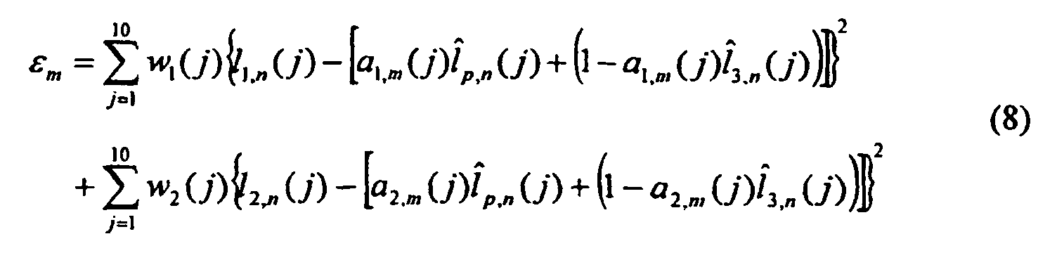
- 3.6.2 Given a particular partition, the codebook is updated. Assume N'
database entries are associated to the centroid A m = (a 1,m ,a 2,m ), then the centroid is
updated using the following equation:
 The interpolation coefficients codebook was trained and tested for several codebook
sizes. A codebook with 16 entries was found to be quite efficient. The above procedure
is readily understood by engineers familiar with the general concepts of vector
quantization and codebook design as described in [7].
The interpolation coefficients codebook was trained and tested for several codebook
sizes. A codebook with 16 entries was found to be quite efficient. The above procedure
is readily understood by engineers familiar with the general concepts of vector
quantization and codebook design as described in [7]. -
- In the 1.2 kbps coder, two gain parameters are calculated per frame, with 6 gains per superframe. The 6 gain parameters are vector-quantized using a 10 bit vector quantizer with a MSE criterion defined in the logarithmic domain.
- The voicing information for the lowest band out of the total of 5 bands is determined from the UN decision. The voicing decisions of the remaining 4 bands are employed only for voiced frames. The binary voicing decisions (1for voiced and 0 for unvoiced) of the 4 bands are quantized using the 2-bit codebook shown in Table 2. This procedure results in two bits being used for voicing in each voiced frame. The bit allocation required in different coding modes for bandpass voicing quantization is shown in Table 6.
- The Fourier magnitude vector is computed only for voiced frames. The quantization procedure for Fourier magnitudes is summarized in Table 7. The unquantized Fourier magnitude vectors for the three frames in a superframe are denoted as f i , i = 1,2,3. Denoted by f 0 is the Fourier magnitude vector of the last frame in the previous superframe, f and i denotes the quantized vector f i , and Q(.) denotes the quantizer function for the Fourier magnitude vector when using the same 8-bit codebook as used within the MELP standard. The quantized Fourier magnitude vectors for the three frames in a superframe are obtained as shown in Table 7.
- The 1.2 kbps coder uses 1-bit per superframe for the quantization of the aperiodic flag. In the 2.4 kbps MELP standard, the aperiodic flag requires one bit per frame, which is three bits per superframe. The compression to one bit per superframe is obtained using the quantization procedure shown in Table 8. In the table, "J" and "-" indicate respectively the aperiodic flag states of set and not set.
- Aside from the parity bit, additional mode error protection techniques are applied to superframes by employing the spare bits that are available in all superframes except the superframes in the VVV mode. The 1.2 kbps coder uses two bits for the quantization of the bandpass voicing for each voiced frame. Hence, in superframes that have one unvoiced frame, two bandpass voicing bits are spare and can be used for mode protection. In superframes that have two unvoiced frames, four bits can be used for mode protection. In
addition 4 bits of LSF quantization are used for mode protection in the UUU and VVU modes. Table 9 shows how these mode protection bits are used. Mode protection implies protection of the coding state, which was described in Section 1.1. - In the UUU mode, the first 8 MSB's of the gain index are divided into two groups of 4 bits and each group is protected by the Hamming (8,4) code. The remaining 2 bits of the gain index are protected with the Hamming (7,4) code. Note that the Hamming (7,4) code corrects single bit-errors, while the (8,4) code corrects single bit errors and in addition detects double bit-errors. The LSF bits for each frame in the UUU superframes are protected by a cyclic redundancy check (CRC) with a CRC (13,9) code which detects single and double bit-errors.
- Within the decoder, the received bits are unpacked from the channel and assembled into parameter codewords. Since the decoding procedures for most parameters depend on the mode (the U/V pattern), the 12 bits allocated for pitch and U/V decisions are decoded first. For the bit pattern 000 in the 3-bit codebook, the 9-bit codeword specifies one of the UUU, UUV, UVU, and VUU modes. If the code of the 9-bit codebook is all-zeros, or has one bit set, the UUU mode is used. If the code has two bits set, or specifies an index unused for pitch, a frame erasure is indicated.
- After decoding the U/V pattern, the resulting mode information is checked using the parity bit and the mode protection bits. If an error is detected, a mode correction algorithm is performed. The algorithm attempts to correct the mode error using the parity bits and mode protection bits. In the case that an uncorrectable error is detected, different decoding methods are applied for each parameter according to the mode error patterns. In addition, if a parity error is found, a parameter-smoothing flag is set. The correction procedures are described in Table 10.
- In the UUU mode, assuming no errors were detected in the mode information, the two (8,4) Hamming codes representing the gain parameters are decoded to correct single bit errors and detect double errors. If an uncorrectable error is detected, a frame erasure is indicated. Otherwise the (7,4) Hamming code for gain and the (13,9) CRC (cyclic redundancy check) codes for LSF's are decoded to correct single errors and detect single and double errors, respectively. If an error is found in the CRC (13,9) codes, the incorrect LSF's are replaced by repeating previous LSF's or interpolating between the neighboring correct LSF's.
- If a frame erasure is detected in the current superframe by the Hamming decoder, or an erasure is directly signaled from the channel, a frame repeat mechanism is implemented. All the parameters of the current superframe are replaced with the parameters from the last frame of the previous superframe.
- For a superframe in which an erasure is not detected, the remaining parameters are decoded. If smoothing is necessary, the post-smoothing parameter is obtained by:
- The pitch decoding is performed as shown in Table 4. For unvoiced frames, the pitch value is set to 50 samples.
- The LSF's are decoded as described in Section 4.4 and Table 5. The LSF's are checked for ascending order and minimum separation.
- The gain index is used to retrieve a codeword containing six gain parameters from the 10-bit VQ gain codebook.
- In the unvoiced frames, all of the bandpass voicing strengths are set to zero. In the voiced frames, Vbp 1 is set to 1 and the remaining voicing patterns are decoded as shown in Table 2.
- The Fourier magnitudes of unvoiced frames are set equal to 1. For the last voiced frame of the current superframe, the Fourier magnitudes are decoded directly. The Fourier magnitudes of other voiced frames are generated by repetition or linear interpolation as shown in Table 7.
- The aperiodic flags are obtained from the new flag as shown in Table 8. The jitter is set to 25% if the aperiodic flag is 1, otherwise the jitter is set to 0%.
- The basic structure of the decoder is the same as in the MELP standard except that a new harmonic synthesis method is introduced to generate the excitation signal for each pitch cycle. In the original 2.4 kbps MELP algorithm, the mixed excitation is generated as the sum of the filtered pulse and noise excitations. The pulse excitation is computed using an inverse discrete Fourier transform (IDFT) of one pitch period in length and the noise excitation is generated in the time domain. In the new harmonic synthesis algorithm, the mixed excitation is generated completely in the frequency domain and then an inverse discrete Fourier transform operation is performed to convert it into the time domain. This avoids the need for bandpass filtering of the pulse and noise excitations, thereby reducing complexity of the decoder.
- In the new harmonic synthesis procedure, the excitation in the frequency domain is generated for each pitch cycle based on the cutoff frequency and the Fourier magnitude vector A 1 , l = 1,2,..., L. The cutoff frequency is obtained from the bandpass voicing parameters as previously described and it is then interpolated for each pitch cycle. The Fourier magnitudes are interpolated in the same way as in the MELP standard.
- With the pitch length denoted as N, the corresponding fundamental frequency is described by: f 0 = 2π/N. The Fourier magnitude vector length is then given by: L = N/2. Two transition frequencies F H and F L are determined from the cutoff frequency F employing an empirically derived algorithm. algorithm as follows,These transition frequencies are equivalent to two frequency component indices V H and V L . A voiced model is used for all the frequency samples below V L , a mixed model is used for frequency samples between V L and V H , and an unvoiced model is used for frequency samples above V H . To define the mixed mode, a gain factor g is selected with the value depending on the cutoff frequency (the higher the cutoff frequency F, the smaller the gain factor).


- The magnitude and phase of the frequency components of the excitation are determined as follows:
 where l is an index identifying a particular frequency component of the IDFT frequency range and 0 is a constant selected so as to avoid a pitch pulse at the pitch cycle boundary. The phase RND (l) is a uniformly distributed random number between -2π and 2π independently generated for each value of l.
- In other words, the spectrum of the mixed excitation signal in each pitch period is modeled by considering three regions of the spectrum, as determined by the cutoff frequency, which determines a transition interval from F L to F H . In the low region, from 0 to F L , the Fourier magnitudes directly determine the spectrum. In the high region, above F H , the Fourier magnitudes are scaled down by the gain factor g. In the transition region, from F L to F H , the Fourier magnitudes are scaled by a linearly decreasing weighting factor that drops from unity to g across the transition region. A linearly increasing phase is used for the low region, and random phases are used for the high region. In the transition region, the phase is the sum of the linear phase and a weighted random phase with the weight increasing linearly from 0 to 1 across the transition region. The frequency samples of the mixed excitation are then converted to the time domain using an inverse Discrete Fourier Transform.
- In some applications, it is important to allow interoperation between two different speech coding schemes. In particular, it is useful to allow interoperability between a 2400 bps MELP coder and a 1200 bps superframe coder. The general operation of a transcoder is illustrated in the block diagrams of Figures 5A and 5B. In the up-converting
transcoder 70 of Fig. 5A, speech isinput 72 to a 1200 bps vocoder 74 whose output is an encoded bit stream at 1200bps 76 which is converted by the "Up-Transcoder" 78 into a 2400 bps bitstream 80 in a form allowing it to be decoded by a 2400bps MELP decoder 82, that outputs synthesizedspeech 84. Conversely, in the down-convertingtranscoder 90 of FIG. 3B speech isinput 92 to a 2400bps MELP encoder 94, which outputs a 2400 bps bitstream 96 into a "Down-Transcoder" 98, that converts the parametric data stream into a 1200 bps bitstream 100 that can be decoded by the 1200bps decoder 102, that outputssynthesized speech 104. In full-duplex (two-way) voice communication both the up-transcoder and the down-transcoder are needed to provide interoperability. - A simple way to implement an up-transcoder is to decode the 1200 bps bit stream with a 1200 bps decoder to obtain a raw digital representation of the recovered speech signal which is then re-encoded with a 2400 bps encoder. Similarly, a simple method for implementing a down-transcoder is to decode the 2400 bps bit stream with a 2400 bps decoder to obtain a raw digital representation of the recovered speech signal which is then re-encoded with a 1200 bps encoder. This approach to implementing up and down transcoders, corresponds to what is called "tandem" encoding and has the disadvantages that the voice quality is substantially degraded and the complexity of the transcoder is unnecessarily high. Transcoder efficiency is improved with the following method for transcoding that reduces complexity while avoiding much of the quality degradation associated with tandem encoding.
- In the down-transcoder, after synchronization and channel error correction decoding are performed, the bits representing each parameter are separately extracted from the bit stream for each of three consecutive frames (constituting a superframe) and the set of parameter information is stored in a parameter buffer. Each parameter set consists of the values of a given parameter for the three consecutive frames. The same methods used to quantize superframe parameters are applied here to each parameter set for recoding into the lower-rate bit stream. For example, the pitch and U/V decision for each of 3 frames in a superframe is applied to the pitch and U/V quantization scheme described in Section 3.2. In this case, the parameter set consists of 3 pitch values each represented with 7 bits and 3 U/V decisions each given by 1 bit, giving a total of 24 bits. This is extracted from the 2400 bps bit stream and the recoding operation converts this into 12 bits to represent the pitch and voicing for the superframe. In this way, the down-transcoder does not have to perform the MELP analysis functions and only performs the needed quantization operations for the superframe. Note that the parity check bit, synchronization bit, and error correction bits must be regenerated as part of the down transcoding operation.
- In the case of an up-transcoder the input bit stream of 1200 bps contains quantized parameters for each superframe. After synchronization and error correction decoding are performed, the up-transcoder extracts the bits representing each parameter for the superframe which are mapped (recoded) into a larger number of bits that specify separately the corresponding values of that parameter for each of the three frames in the current superframe. The method of performing this mapping, which is parameter dependent, is described below. Once all parameters for a frame of the superframe have been determined, the sequence of bits representing three frames of speech are generated. From this data sequence, the 2400 bps bit stream is generated, after insertion of the synchronization bit, parity bit, and error correction encoding.
- The following is a description of the general approach to mapping (decoding) the parameter bits for a superframe into separate parameter bits for each of the three frames. Quantization tables and codebooks are used in the 1200 bps decoder for each parameter as described previously. The decoding operation takes a binary word that represents one or more parameters and outputs a value for each parameter, e.g. a particular LSF value or pitch value as stored in a codebook. The parameter values are requantized, i.e. applied as input to a new quantizing operation employing the quantization tables of the 2400 bps MELP coder. This requantization leads to a new binary word that represents the parameter values in a form suitable for decoding by the 2400 bps MELP decoder.
- As an example to illustrate the use of requantization, from the 1200 bps bit stream, the bits containing the pitch and voicing information for a particular superframe are extracted and decoded into 3 voicing (V/U) decisions and 3 pitch values for the 3 frames in the superframe; The 3 voicing decisions are binary and are directly usable as the voicing bits for the 2400 bps MELP bitstream (one bit for each of 3 frames). The 3 pitch values are requantized by applying each to the MELP pitch scalar quantizer obtaining a 7 bit word for each pitch value. Numerous alternative implementation of pitch requantization which follow the inventive method described can be designed by a person skilled in the art.
- One specific alteration can be created by bypassing pitch requantization when only a single frame of the superframe is voiced, since in this case the pitch value for the voiced frame is already specified in quantized form consistent with the format of the MELP vocoder. Similarly, for the Fourier magnitudes, requantization is not needed for the last frame of a superframe since it is has already been scalar quantized in the MELP format. However the interpolated Fourier magnitudes for the other two frames of the superframe need to be requantized by the MELP quantization scheme. The jitter, or aperiodic flag, is simply obtained by table lookup using the last two columns of Table 8.
- FIG. 6 shows a digital vocoder terminal containing an encoder and decoder that operate in accordance with the voice coding methods and apparatus of this invention. The
microphone MIC 112 is an input speech transducer providing ananalog output signal 114 which is sampled and digitized by an Analog to Digital Converter (A/D) 116. The resulting sampled and digitizedspeech 118 is digitally processed and compressed within a DSP/controller chip 120, by the voice encoding operations performed in the Encodeblock 122, which is implemented in software within the DSP/Controller according to the invention. - The digital signal processor (DSP)120 is exemplified by the Texas Instruments TMC320C5416 integrated circuit, which contains random access memory (RAM) providing sufficient buffer space for storing speech data and intermediate data and parameters; the DSP circuit also contains read-only memory (ROM) for containing the program instructions, as previously described, to implement the vocoder operations. A DSP is well suited for performing the vocoder operations described in this invention. The resultant bitstream from the
encoding operation 124 is a low rate bit-stream, Tx data stream. TheTx data 124 enters aChannel Interface Unit 126 to be transmitted over achannel 128. - On the receiving side, data from a
channel 128 enters aChannel Interface Unit 126 which outputs an Rx bit-stream 130. TheRx data 130 is applied to a set of voice decoding operations within the decode block; the operations have been previously described. The resulting sampled and digitizedspeech 134, is applied to a Digital to Analog Converter (D/A) 136. The D/A outputs reconstructedanalog speech 138. The reconstructedanalog speech 138 is applied to aspeaker 140, or other audio transducer which reproduces the reconstructed sound. - FIG. 6 is a representation of one configuration of hardware on which the inventive principles may be practiced. The inventive principles may be practiced on various forms of vocoder implementations that can support the processing functions described herein for the encoding and decoding of the speech data. Specifically the following are but a few of the many variations included within the scope of the inventive implementation:
- (a) Using Channel Interface Units which contain a voiceband data modem for use when the transmission path is a conventional telephone line.
- (b) Using encrypted digital signals for transmission and described for reception via a suitable encryption device to provide secure transmission. In this case, the encryption unit would also be contained in the Channel Interface Unit.
- (c) Using a Channel Interface Unit that contains a radio frequency modulator and demodulator for wireless signal transmission by radio waves for cases in which the transmission channel is a wireless radio link.
- (d) Using a Channel Interface Unit that contains multiplexing and demultiplexing equipment for sharing a common transmission channel with multiple voice and/or data channels. In this case multiple Tx and Rx signals would be connected to the Channel Interface Unit.
- (e) Employing discrete components, or a mix of discrete elements and processing elements, to replace the instruction processing operations of the DSP/Controller. Examples that could be employed include programmable gate arrays (PGAs). It must be noted that the invention can be fully reduced to practice in hardware, without the need of a processing element.
-
- Hardware to support the inventive principles need only support the data operations described. However, use of a DSP/processor chips are the most common circuits used for implementing speech coders or vocoders in the current state of the art.
- Although the description above contains many specificities, these should not be construed as limiting the scope of the invention but as merely providing illustrations of some of the presently preferred embodiments of this invention. Thus the scope of this invention should be determined by the appended claims and their legal equivalents.
Bit Allocation of both 2.4 kbps and 1.2 kbps Coding Schemes Parameters Bits for quantization of three frames(540 samples) 2.4 kbps Voiced 2.4kbps Unvoiced 1.2 kbps state 11.2 kb state 21.2 kb state 31.2 kb state 41.2 kbps state 5Pitch & Global UV Decisions 7*3 7*3 12 12 12 12 12 Parity 0 0 1 1 1 1 1 LSF's 25*3 25*3 42 42 39 42 27 Gains 8*3 8*3 10 10 10 10 10 Bandpass Voicing 4*3 0 6 4 4 2 0 Fourier Magnitudes 8*3 0 8 8 8 8 0 Jitter 1*3 0 1 1 1 1 0 Synchronization 1*3 1*3 1 1 1 1 1 Error Protection 0 13*3 0 2 5 4 30 Total 162 162 81 81 81 81 81 *Note: 1.2kbps State 1: All three frames are voiced.
1.2kbps State 2: One of the first two frames is unvoiced, other frames are voiced.
1.2kbps State 3: The 1st and 2nd frames are voiced. The 3rd frame is unvoiced.
1.2kbps State 4: One of the three frames is voiced, other two frames are unvoiced.
1.2kbps State 5: All three frames are unvoiced.Bandpass voicing index mapping Codeword: 0000 1000 1100 1111 0000 1000 1100 0111 Voicing patterns patterns assigned to the codeword. 0001 1001 1011 0010 1010 1101 0011 1110 0100 1111 0101 0110 Cutoff Frequency 500 Hz 1000 Hz 2000 Hz 4000 Hz Pitch quantization schemes U/V pattern Pitch quantization method U U U N/A U U V The pitch of the only voiced frame is scalar quantized using a 7-bit quantizer. V U U U V V The pitches of the voiced frames are quantized using the same VQ as for the VVV case. A weighting function is applied which takes into account the U/V information. V U V V V U V V V Vector quantization of three pitches Joint quantization scheme of pitch and voicing decisions U/V patterns 3-bit codewords 9-bit codebooks UUU 000 The pitch value is quantized with the same 99-level uniform quantizer as in the 2.4kbps standard. The pitch value and U/V pattern are then mapped to a codevector in this 9-bit codebook. UUV UVU VUU VVU 001 These U/V patterns share the same codebook containing 512 codevectors of the pitch triple. VUV 010 UVV 100 VVV 011 512-entry codebook A 101 512- entry codebook B 110 512-entry codebook C 111 512-entry codebook D Bit allocation for LSF quantization according to UV decisions U/V pattern LSF l 1 LSF l 2 LSF l 3 Interpolation on Residual of l 1 and l 2 Total U U U 9 9 9 0 0 27 V U U 8+6+5+5 9 9 0 0 42 U V U 9 8+6+5+5 9 0 0 42 U U V 9 9 8+6+5+5 0 0 42 U V V V U V 0 0 8+6+5+5 4 8+6 42 V V V V V U 0 0 9 4 8+6+6+6 39 Bit Allocation for bandpass voicing quantization UV decisions pattern VVV VVU, VUV, UVV VUU, UVU, UUV UUU Bits for bandpass voicing information 6 4 2 0 . Fourier magnitude vector quantization U/V pattern for current superframe U/V decision for the last frame of the previous superframe U V UUU N/A VUU f and 1 = Q(f 1 ) UVU f and 2 = Q(f 2) UUV f and 3 = Q(f 3 ) UVV f and 3 = Q(f 3 ), f and 2 = f and 3 VUV f and 3 = Q(f 3), f and 1 = f and 3 f and 3 = Q(f 3), f and 1 = f and 0 VVU f and 2 = Q(f 2 ), f and 1 = f and 2 f and 2 = Q(f 2 ), f and 1 = f and 0 + f and 2 2 VVV f and 2 = Q(f 2), f and 1 =f and 2 = f and 3 f and 3 = Q(f 3 ), f and 1 = 2 · f and 0 + f and 3 3, f and 2 = f and 0 + 2 · f and 3 Aperiodic flag quantization using 1 bit U/V pattern Quantization Procedure Quantization Patterns New flag = 0 New flag=1 U U U N/A J J J J J J U V U If the voiced frame has aperiodic flag, set new flag. J J - J J J U V U J - J J J J V U U - J J J J J U V V If the second frame has aperiodic flag, set new flag. J - - J J - V V U - - J - J J V U V N/A -J- - J - V V V If> 1 frame has the aperiodic flag set, set new flag. - - - J J J Mode protection schemes U/V pattern 3-b codebook of joint quantization for pitch and U/V decisions Bit pattern of bandpass bandpass voicing 1 Bit pattern of voicing 2 Bit pattern LSF U U U 000 00 00 0000 U U V 00 01 - U V U 00 10 - V U U 00 11 - V V U 001 01 - 0101 V U V 010 10 - - U V V 100 11 - - V V V 011, 101, 110, 111 - - - - Parameter decoding schemes if a mode error is detected U/V pattern Corrected U/V U/V pattern LSF's LSF's Gain Gain Pitch Pitch Bandpass Bandpass voicing voicing Fourier Fourier Magnitude Magnitude UUU U U U Repeat LSF's of the last frame in the previous superframe Decode and apply smoothing Set to 0 Set to 1 all magnitudes UUV UUU VUU VVU V V V Decode and apply smoothing Decode and apply smoothing Decode and apply smoothing Set the first band to 1, others to 0 VUV VVU VVV
Claims (23)
- A voice compression apparatus (10), comprising:characterized bya superframe buffer (14) for receiving multiple frames of voice data (12);a frame-based encoder analysis module for analyzing characteristics of voice data within frames contained in the superframe to produce an associated set of voice data parameters; anda superframe encoder for receiving voice data parameters from the analysis module for a group of frames contained within the superframe buffer (14), for reducing by analysis data for the group of frames and for quantizing and encoding said data into an outgoing digital bit stream for transmission;
said superframe encoder comprising a pitch smoother (24) wherein pitch smoothing calculations are based on an onset/offset frame classifier. - A voice compression apparatus (10) as recited in claim 1, wherein the analysis module is capable of receiving voice data parameters selected from the group of voice encoders consisting of linear predictive coders, mixed-excitation linear prediction coders, harmonic coders, and multiband excitation coders.
- A voice compression apparatus (10) as recited in claim 1, wherein said superframe encoder includes at least two parametric processing modules selected from the group of parametric processing modules consisting of pitch smoothers (24), bandpass voicing smoothers (30), linear predictive quantizers (34), jitter quantizers (36), and Fourier magnitude quantizers (38).
- A voice compression apparatus (10) as recited in any one of claims 1 to 3, wherein said superframe encoder includes a vector quantizer (28) wherein pitch values within a superframe are vector quantized with a distortion measure of said vector quantizer (28) being responsive to the pitch errors.
- A voice compression apparatus (10) as recited in any one of claims 1 to 3, wherein said superframe encoder includes a vector quantizer (28) wherein pitch values within a superframe are vector quantized with a distortion measure of said vector quantizer (28) being responsive to the pitch differentials as well as to the pitch errors.
- A voice compression apparatus (10) as recited in any one of claims 1 to 3, wherein said superframe encoder includes a quantizer of linear prediction parameters, wherein quantization is performed with a codebook-based interpolation of linear prediction parameters that employ different interpolation coefficients for each linear prediction parameter, and wherein said quantizer operates in closed loop mode to minimize overall error over a number of frames.
- A voice compression apparatus (10) as recited in claim 6, wherein said quantizer is capable of performing a line spectral frequency, LSF, quantization using said codebook-based interpolation.
- A voice compression apparatus (10) as recited in claim 7, wherein said codebook is created by means of a training database operated on by a centroid-based training procedure.
- A voice compression apparatus (10) as recited in claim 1, wherein said pitch smoother (24) is further adapted to calculate pitch trajectory using a plurality of voicing decisions.
- A voice compression apparatus (10) as recited in claim 9, wherein said pitch smoother classfies frames into onset and offset frames based on at least four waveform feature parameters selected from the group of waveform feature parameters consisting of energy, zero-crossing rate, peakiness, maximum correlation coefficient of input speech, maximum correlation coefficient of 500 Hz low pass filtered speech, energy of low pass filtered speech, and energy of high pass filtered speech.
- A voice compression apparatus (10) as recited in any one of claims 1 to 10, wherein said frame-based encoder analysis module uses a Mixed Excitation Linear Prediction, MELP, analysis algorithm, and said superframe encoder includes a bandpass voicing smoother (30) for mapping multiband voicing decisions for each frame into a single cutoff frequency for that frame, wherein said cutoff frequency takes on one value from a predetermined list of allowable values.
- A voice compression apparatus (10) as recited in claim 11, wherein said bandpass voicing smoother (30) performs smoothing by modifying the cutoff frequency of a frame as a function of the cutoff frequencies of neighboring frames and the average frame energy.
- A voice compression apparatus (10) as recited in claim 1, further comprising means for compressing aperiodic flag bits for each frame in a superframe into a single bit per superframe, which bit is created based on the distribution of voiced and unvoiced frames within the superframe.
- A voice compression apparatus (10) as recited in claim 1, wherein said superframe encoder includes a plurality of quantizers (28, 32, 34, 36, 38) for encoding parametric data into a set of bits, wherein at least one of said quantizers employs vector quantization to represent interpolation coefficients.
- A voice compression apparatus (10) as recited in claim 1, wherein a superframe is categorized into one of a plurality of coding states based on the combination of voiced and unvoiced frames within the superframe, and wherein each of said coding states is associated with a different bit allocation to be used with the superframe.
- A voice compression apparatus (10) as recited in claim 1, wherein said frame-based encoder analysis module uses a Mixed Excitation Linear Prediction, MELP, analysis algorithm, and said pitch smoother (24) is adapted to determine pitch and U/V decisions for each frame of the superframe and extracts parameters needed for frame classification into onset and offset frames, said superframe encoder further comprising:a bandpass voicing smoother (30) for determining bandpass voicing strengths for the frames within the superframe and for determining cutoff frequencies for each frame, anda parameter quantizer and encoder for quantizing and encoding voicing parameters received from said analysis module, said pitch smoother (24), and said bandpass voicing smoother (30) into a set of bits and encoding said bits into an outgoing digital bit stream for transmission.
- A voice compression apparatus (10) as recited in any one of claims 1 to 16, further comprising:a superframe decoder (54) for receiving and decoding a digital bit stream encoded with superframe voice data into quantized frame-based parameters; anda frame-based decoder synthesizer for receiving the quantized parameters for each frame (62, 64, 66) and decoding the quantized parameters into a synthesized voice output (68), whereinsaid voice compression apparatus (10), said superframe decoder (54) and said frame-based decoder synthesizer are comprised in a vocoder apparatus (110).
- A voice decoder apparatus (50), comprising:characterized bya superframe decoder (54) for receiving an incoming digital bit stream as a series of superframes and decoding and inverse quantizing said superframes into quantized frame-based voice parameters; anda frame-based decoder for receiving said quantized frame-based voice parameters and combining said quantized frame-based voice parameters into a synthesized voice output signal;
said frame-based decoder being adapted for decoding the parametric voice encoded data stream from said superframe decoder (54) into an audio voice signal by performing:buffering the received parametric voice data stream having a plurality of pitch periods and loading said buffered frame data into a buffer;constructing an estimated spectrum of excitation within each pitch period by breaking down the frequency spectrum into regions based on cutoff frequency, wherein said construction comprises:computing Fourier magnitude for each region, wherein the resultant computed Fourier magnitudes for at least one of said regions is then scaled by a gain factor computed for that region,computing phase within each region, wherein the resultant phase for at least one of said regions has been modified by use of a weighted random phase,andconverting said Fourier magnitude and said phase within each region to a time domain representation by the computation of an inverse discrete Fourier transform; andgenerating an analog voice signal (68) from said time domain representation. - The voice decoder apparatus (50) as recited in claim 18, wherein said regions through which the frequency spectrum is broken down into comprise:a lower region wherein Fourier magnitudes directly determine the spectrum;a transition region wherein Fourier magnitudes are scaled down by a linearly decreasing weighting factor that drops from unity to a nonzero positive value dependent on the cutoff frequency of the current frame; andan upper region wherein Fourier magnitudes are scaled down by a weighting factor dependent on the cutoff frequency of the current frame.
- A system (70) comprising the voice compression apparatus (10; 74) as recited in any of claims 1 to 16 and an up-transcoder apparatus (78), the up-transcoder apparatus (78) being adapted to receive a superframe encoded voice data stream (76) from said voice compression apparatus (10; 74) and to convert the superframe encoded voice data stream (76) to a frame-based encoded voice data stream (80), said up-transcoder apparatus (78) comprising:a superframe buffer for collecting superframe data and extracting bits representing superframe parameters;a decoder for inverse quantizing the bits for each set of superframe parameters into a set of quantized parameter values for each frame of the superframe; anda frame-based encoder for quantizing the voice parameters for each of the underlying frames, mapping said quantized voice parameters into frame-based data, and producing a frame-based voiced data stream (80).
- A system (90) comprising the voice decoder apparatus (50; 102) as recited in claim 18 or 19 and a down-transcoder apparatus (98) which is adapted to receive an encoded frame-based voice data stream (96) and to convert it into a superframe-based encoded voice data stream (100) as decodable by said voice decoder apparatus (50; 102); said down-transcoder apparatus (98) comprising:a superframe buffer for collecting a number of frames of parametric voice data and extracting bits representing frame-based voice parameters;a decoder for inverse quantizing the bits for each frame of parameter into quantized parameter values for each frame; anda superframe encoder for collecting said quantized frame-based parameters for the group of frames within the superframe, producing a set of parametric voice data, and quantizing and encoding said parametric voice data into an outgoing digital bit stream (100).
- A vocoder method for encoding digitized voice into parametric voice data, comprising the steps of:loading multiple frames of digitized voice into a superframe buffer,encoding digitized voice within each frame of the superframe buffer using a Mixed Excitation Linear Prediction, MELP, analysis algorithm by parametric analysis to produce frame-based parametric voice data;classifying frames as onset frames and offset frames by calculating pitch and UN parameters within each frame of the superframe and using said classification for performing speech smoothing;determining a cutoff frequency for each frame within the superframe by calculating a bandpass voicing strength parameter for the frames within the superframe buffer;collecting a set of superframe parameters from the parametric analysis, frame classification, and cutoff frequency determination steps for the group of frames within the superframe;quantizing the superframe parameters into discrete values represented by a reduced set of data bits that form quantized superframe parameter data; andencoding quantized superframe parameter data into a data stream of superframe-based parametric voice data that contains substantially equivalent voice information to the frame-based parametric voice data, yet at a lower bit per second rate of encoded voice.
- A vocoder method for producing digitized voice from superframe-based parametric voice data, comprising the steps of:characterized byreceiving superframe-based parametric voice data in a superframe buffer;decoding and inverse quantizing the voice data within the superframe buffer to recreate a set of frame-based voice parameter values; anddecoding the frame-based voice parameters with a frame-based voice synthesizer which decodes the frame-based voice parameters to produce a digitized voice output;
said step of decoding the frame-based voice parameters comprises:buffering the received parametric voice data stream having a plurality of pitch periods and loading said buffered frame data into a buffer;constructing an estimated spectrum of excitation within each pitch period by breaking down the frequency spectrum into regions based on cutoff frequency, wherein said construction comprises:computing Fourier magnitude for each region, wherein the resultant computed Fourier magnitudes for at least one of said regions is then scaled by a gain factor computed for that region,computing phase within each region, wherein the resultant phase for at least one of said regions has been modified by use of a weighted random phase, andconverting said Fourier magnitude and said phase within each region to a time domain representation by the computation of an inverse discrete Fourier transform; andgenerating an analog voice signal (68) from said time domain representation.
Applications Claiming Priority (3)
| Application Number | Priority Date | Filing Date | Title |
|---|---|---|---|
| US401068 | 1989-08-31 | ||
| US09/401,068 US7315815B1 (en) | 1999-09-22 | 1999-09-22 | LPC-harmonic vocoder with superframe structure |
| PCT/US2000/025869 WO2001022403A1 (en) | 1999-09-22 | 2000-09-20 | Lpc-harmonic vocoder with superframe structure |
Publications (2)
| Publication Number | Publication Date |
|---|---|
| EP1222659A1 EP1222659A1 (en) | 2002-07-17 |
| EP1222659B1 true EP1222659B1 (en) | 2005-11-16 |
Family
ID=23586142
Family Applications (1)
| Application Number | Title | Priority Date | Filing Date |
|---|---|---|---|
| EP00968376A Expired - Lifetime EP1222659B1 (en) | 1999-09-22 | 2000-09-20 | Lpc-harmonic vocoder with superframe structure |
Country Status (9)
| Country | Link |
|---|---|
| US (2) | US7315815B1 (en) |
| EP (1) | EP1222659B1 (en) |
| JP (2) | JP4731775B2 (en) |
| AT (1) | ATE310304T1 (en) |
| AU (1) | AU7830300A (en) |
| DE (1) | DE60024123T2 (en) |
| DK (1) | DK1222659T3 (en) |
| ES (1) | ES2250197T3 (en) |
| WO (1) | WO2001022403A1 (en) |
Cited By (1)
| Publication number | Priority date | Publication date | Assignee | Title |
|---|---|---|---|---|
| TWI413096B (en) * | 2009-10-08 | 2013-10-21 | Chunghwa Picture Tubes Ltd | Adaptive frame rate modulation system and method thereof |
Families Citing this family (66)
| Publication number | Priority date | Publication date | Assignee | Title |
|---|---|---|---|---|
| US7295974B1 (en) * | 1999-03-12 | 2007-11-13 | Texas Instruments Incorporated | Encoding in speech compression |
| US6959274B1 (en) * | 1999-09-22 | 2005-10-25 | Mindspeed Technologies, Inc. | Fixed rate speech compression system and method |
| EP1168734A1 (en) * | 2000-06-26 | 2002-01-02 | BRITISH TELECOMMUNICATIONS public limited company | Method to reduce the distortion in a voice transmission over data networks |
| US20030028386A1 (en) * | 2001-04-02 | 2003-02-06 | Zinser Richard L. | Compressed domain universal transcoder |
| US7421304B2 (en) * | 2002-01-21 | 2008-09-02 | Kenwood Corporation | Audio signal processing device, signal recovering device, audio signal processing method and signal recovering method |
| US8090577B2 (en) * | 2002-08-08 | 2012-01-03 | Qualcomm Incorported | Bandwidth-adaptive quantization |
| WO2004090864A2 (en) * | 2003-03-12 | 2004-10-21 | The Indian Institute Of Technology, Bombay | Method and apparatus for the encoding and decoding of speech |
| WO2004090870A1 (en) * | 2003-04-04 | 2004-10-21 | Kabushiki Kaisha Toshiba | Method and apparatus for encoding or decoding wide-band audio |
| EP1618557B1 (en) * | 2003-05-01 | 2007-07-25 | Nokia Corporation | Method and device for gain quantization in variable bit rate wideband speech coding |
| US20050049853A1 (en) * | 2003-09-01 | 2005-03-03 | Mi-Suk Lee | Frame loss concealment method and device for VoIP system |
| FR2867648A1 (en) * | 2003-12-10 | 2005-09-16 | France Telecom | TRANSCODING BETWEEN INDICES OF MULTI-IMPULSE DICTIONARIES USED IN COMPRESSION CODING OF DIGITAL SIGNALS |
| US7668712B2 (en) * | 2004-03-31 | 2010-02-23 | Microsoft Corporation | Audio encoding and decoding with intra frames and adaptive forward error correction |
| US20050232497A1 (en) * | 2004-04-15 | 2005-10-20 | Microsoft Corporation | High-fidelity transcoding |
| FR2869151B1 (en) * | 2004-04-19 | 2007-01-26 | Thales Sa | METHOD OF QUANTIFYING A VERY LOW SPEECH ENCODER |
| ES2338117T3 (en) * | 2004-05-17 | 2010-05-04 | Nokia Corporation | AUDIO CODING WITH DIFFERENT LENGTHS OF CODING FRAME. |
| US7596486B2 (en) * | 2004-05-19 | 2009-09-29 | Nokia Corporation | Encoding an audio signal using different audio coder modes |
| US8065139B2 (en) * | 2004-06-21 | 2011-11-22 | Koninklijke Philips Electronics N.V. | Method of audio encoding |
| WO2006028009A1 (en) * | 2004-09-06 | 2006-03-16 | Matsushita Electric Industrial Co., Ltd. | Scalable decoding device and signal loss compensation method |
| US7418387B2 (en) * | 2004-11-24 | 2008-08-26 | Microsoft Corporation | Generic spelling mnemonics |
| US7353010B1 (en) * | 2004-12-22 | 2008-04-01 | Atheros Communications, Inc. | Techniques for fast automatic gain control |
| US8219391B2 (en) * | 2005-02-15 | 2012-07-10 | Raytheon Bbn Technologies Corp. | Speech analyzing system with speech codebook |
| US7797156B2 (en) * | 2005-02-15 | 2010-09-14 | Raytheon Bbn Technologies Corp. | Speech analyzing system with adaptive noise codebook |
| US8160868B2 (en) * | 2005-03-14 | 2012-04-17 | Panasonic Corporation | Scalable decoder and scalable decoding method |
| US7848220B2 (en) * | 2005-03-29 | 2010-12-07 | Lockheed Martin Corporation | System for modeling digital pulses having specific FMOP properties |
| US7177804B2 (en) | 2005-05-31 | 2007-02-13 | Microsoft Corporation | Sub-band voice codec with multi-stage codebooks and redundant coding |
| US7831421B2 (en) * | 2005-05-31 | 2010-11-09 | Microsoft Corporation | Robust decoder |
| US7707034B2 (en) * | 2005-05-31 | 2010-04-27 | Microsoft Corporation | Audio codec post-filter |
| WO2007000988A1 (en) * | 2005-06-29 | 2007-01-04 | Matsushita Electric Industrial Co., Ltd. | Scalable decoder and disappeared data interpolating method |
| US20070011009A1 (en) * | 2005-07-08 | 2007-01-11 | Nokia Corporation | Supporting a concatenative text-to-speech synthesis |
| WO2007066771A1 (en) * | 2005-12-09 | 2007-06-14 | Matsushita Electric Industrial Co., Ltd. | Fixed code book search device and fixed code book search method |
| WO2007124485A2 (en) * | 2006-04-21 | 2007-11-01 | Dilithium Networks Pty Ltd. | Method and apparatus for audio transcoding |
| US8589151B2 (en) * | 2006-06-21 | 2013-11-19 | Harris Corporation | Vocoder and associated method that transcodes between mixed excitation linear prediction (MELP) vocoders with different speech frame rates |
| US8239190B2 (en) | 2006-08-22 | 2012-08-07 | Qualcomm Incorporated | Time-warping frames of wideband vocoder |
| US7953595B2 (en) * | 2006-10-18 | 2011-05-31 | Polycom, Inc. | Dual-transform coding of audio signals |
| US7966175B2 (en) * | 2006-10-18 | 2011-06-21 | Polycom, Inc. | Fast lattice vector quantization |
| US8489392B2 (en) | 2006-11-06 | 2013-07-16 | Nokia Corporation | System and method for modeling speech spectra |
| US20080162150A1 (en) * | 2006-12-28 | 2008-07-03 | Vianix Delaware, Llc | System and Method for a High Performance Audio Codec |
| US7937076B2 (en) * | 2007-03-07 | 2011-05-03 | Harris Corporation | Software defined radio for loading waveform components at runtime in a software communications architecture (SCA) framework |
| US8315709B2 (en) * | 2007-03-26 | 2012-11-20 | Medtronic, Inc. | System and method for smoothing sampled digital signals |
| CN101030377B (en) * | 2007-04-13 | 2010-12-15 | 清华大学 | Method for increasing base-sound period parameter quantified precision of 0.6kb/s voice coder |
| US8457958B2 (en) | 2007-11-09 | 2013-06-04 | Microsoft Corporation | Audio transcoder using encoder-generated side information to transcode to target bit-rate |
| US8842558B2 (en) * | 2008-01-02 | 2014-09-23 | Interdigital Patent Holdings, Inc. | Configuration for CQI reporting in LTE |
| US8175169B2 (en) * | 2008-02-15 | 2012-05-08 | Research In Motion Limited | Method and system for optimizing quantization for noisy channels |
| CN102089810B (en) * | 2008-07-10 | 2013-05-08 | 沃伊斯亚吉公司 | Multi-reference LPC filter quantization and inverse quantization device and method |
| US8972828B1 (en) * | 2008-09-18 | 2015-03-03 | Compass Electro Optical Systems Ltd. | High speed interconnect protocol and method |
| KR101622950B1 (en) * | 2009-01-28 | 2016-05-23 | 삼성전자주식회사 | Method of coding/decoding audio signal and apparatus for enabling the method |
| US8311115B2 (en) | 2009-01-29 | 2012-11-13 | Microsoft Corporation | Video encoding using previously calculated motion information |
| US8396114B2 (en) * | 2009-01-29 | 2013-03-12 | Microsoft Corporation | Multiple bit rate video encoding using variable bit rate and dynamic resolution for adaptive video streaming |
| TWI465122B (en) | 2009-01-30 | 2014-12-11 | Dolby Lab Licensing Corp | Method for determining inverse filter from critically banded impulse response data |
| US8270473B2 (en) * | 2009-06-12 | 2012-09-18 | Microsoft Corporation | Motion based dynamic resolution multiple bit rate video encoding |
| PL2473995T3 (en) * | 2009-10-20 | 2015-06-30 | Fraunhofer Ges Forschung | Audio signal encoder, audio signal decoder, method for providing an encoded representation of an audio content, method for providing a decoded representation of an audio content and computer program for use in low delay applications |
| ES2374008B1 (en) * | 2009-12-21 | 2012-12-28 | Telefónica, S.A. | CODING, MODIFICATION AND SYNTHESIS OF VOICE SEGMENTS. |
| US8705616B2 (en) | 2010-06-11 | 2014-04-22 | Microsoft Corporation | Parallel multiple bitrate video encoding to reduce latency and dependences between groups of pictures |
| US9591318B2 (en) | 2011-09-16 | 2017-03-07 | Microsoft Technology Licensing, Llc | Multi-layer encoding and decoding |
| TWI453733B (en) * | 2011-12-30 | 2014-09-21 | Nyquest Corp Ltd | Device and method for audio quantization codec |
| US9070362B2 (en) | 2011-12-30 | 2015-06-30 | Nyquest Corporation Limited | Audio quantization coding and decoding device and method thereof |
| US11089343B2 (en) | 2012-01-11 | 2021-08-10 | Microsoft Technology Licensing, Llc | Capability advertisement, configuration and control for video coding and decoding |
| EP2830058A1 (en) * | 2013-07-22 | 2015-01-28 | Fraunhofer-Gesellschaft zur Förderung der angewandten Forschung e.V. | Frequency-domain audio coding supporting transform length switching |
| EP2863386A1 (en) * | 2013-10-18 | 2015-04-22 | Fraunhofer-Gesellschaft zur Förderung der angewandten Forschung e.V. | Audio decoder, apparatus for generating encoded audio output data and methods permitting initializing a decoder |
| ITBA20130077A1 (en) * | 2013-11-25 | 2015-05-26 | Cicco Luca De | MECHANISM FOR CHECKING THE CODING BITRATES IN AN ADAPTIVE VIDEO STREAMING SYSTEM BASED ON PLAYOUT BUFFERS AND BAND ESTIMATE. |
| CN104078047B (en) * | 2014-06-21 | 2017-06-06 | 西安邮电大学 | Quantum compression method based on voice Multi-Band Excitation LSP parameters |
| CN107924683B (en) * | 2015-10-15 | 2021-03-30 | 华为技术有限公司 | Sinusoidal coding and decoding method and device |
| US10373608B2 (en) | 2015-10-22 | 2019-08-06 | Texas Instruments Incorporated | Time-based frequency tuning of analog-to-information feature extraction |
| US10332543B1 (en) * | 2018-03-12 | 2019-06-25 | Cypress Semiconductor Corporation | Systems and methods for capturing noise for pattern recognition processing |
| WO2020145472A1 (en) * | 2019-01-11 | 2020-07-16 | 네이버 주식회사 | Neural vocoder for implementing speaker adaptive model and generating synthesized speech signal, and method for training neural vocoder |
| CN111818519B (en) * | 2020-07-16 | 2022-02-11 | 郑州信大捷安信息技术股份有限公司 | End-to-end voice encryption and decryption method and system |
Family Cites Families (72)
| Publication number | Priority date | Publication date | Assignee | Title |
|---|---|---|---|---|
| US4969192A (en) | 1987-04-06 | 1990-11-06 | Voicecraft, Inc. | Vector adaptive predictive coder for speech and audio |
| US4815134A (en) | 1987-09-08 | 1989-03-21 | Texas Instruments Incorporated | Very low rate speech encoder and decoder |
| CN1062963C (en) | 1990-04-12 | 2001-03-07 | 多尔拜实验特许公司 | Adaptive-block-lenght, adaptive-transform, and adaptive-window transform coder, decoder, and encoder/decoder for high-quality audio |
| US5664051A (en) * | 1990-09-24 | 1997-09-02 | Digital Voice Systems, Inc. | Method and apparatus for phase synthesis for speech processing |
| JPH04249300A (en) * | 1991-02-05 | 1992-09-04 | Kokusai Electric Co Ltd | Method and device for voice encoding and decoding |
| US5255339A (en) * | 1991-07-19 | 1993-10-19 | Motorola, Inc. | Low bit rate vocoder means and method |
| US5734789A (en) | 1992-06-01 | 1998-03-31 | Hughes Electronics | Voiced, unvoiced or noise modes in a CELP vocoder |
| JP2746039B2 (en) | 1993-01-22 | 1998-04-28 | 日本電気株式会社 | Audio coding method |
| US5717823A (en) | 1994-04-14 | 1998-02-10 | Lucent Technologies Inc. | Speech-rate modification for linear-prediction based analysis-by-synthesis speech coders |
| JP3277705B2 (en) | 1994-07-27 | 2002-04-22 | ソニー株式会社 | Information encoding apparatus and method, and information decoding apparatus and method |
| TW271524B (en) | 1994-08-05 | 1996-03-01 | Qualcomm Inc | |
| US5699477A (en) | 1994-11-09 | 1997-12-16 | Texas Instruments Incorporated | Mixed excitation linear prediction with fractional pitch |
| US5751903A (en) | 1994-12-19 | 1998-05-12 | Hughes Electronics | Low rate multi-mode CELP codec that encodes line SPECTRAL frequencies utilizing an offset |
| US5668925A (en) | 1995-06-01 | 1997-09-16 | Martin Marietta Corporation | Low data rate speech encoder with mixed excitation |
| US5699485A (en) | 1995-06-07 | 1997-12-16 | Lucent Technologies Inc. | Pitch delay modification during frame erasures |
| US5774837A (en) | 1995-09-13 | 1998-06-30 | Voxware, Inc. | Speech coding system and method using voicing probability determination |
| US5835495A (en) | 1995-10-11 | 1998-11-10 | Microsoft Corporation | System and method for scaleable streamed audio transmission over a network |
| TW321810B (en) | 1995-10-26 | 1997-12-01 | Sony Co Ltd | |
| IT1281001B1 (en) | 1995-10-27 | 1998-02-11 | Cselt Centro Studi Lab Telecom | PROCEDURE AND EQUIPMENT FOR CODING, HANDLING AND DECODING AUDIO SIGNALS. |
| US5778335A (en) | 1996-02-26 | 1998-07-07 | The Regents Of The University Of California | Method and apparatus for efficient multiband celp wideband speech and music coding and decoding |
| US6041345A (en) | 1996-03-08 | 2000-03-21 | Microsoft Corporation | Active stream format for holding multiple media streams |
| JP3335841B2 (en) | 1996-05-27 | 2002-10-21 | 日本電気株式会社 | Signal encoding device |
| US6570991B1 (en) | 1996-12-18 | 2003-05-27 | Interval Research Corporation | Multi-feature speech/music discrimination system |
| US6317714B1 (en) | 1997-02-04 | 2001-11-13 | Microsoft Corporation | Controller and associated mechanical characters operable for continuously performing received control data while engaging in bidirectional communications over a single communications channel |
| US6134518A (en) | 1997-03-04 | 2000-10-17 | International Business Machines Corporation | Digital audio signal coding using a CELP coder and a transform coder |
| US6292834B1 (en) | 1997-03-14 | 2001-09-18 | Microsoft Corporation | Dynamic bandwidth selection for efficient transmission of multimedia streams in a computer network |
| US6131084A (en) * | 1997-03-14 | 2000-10-10 | Digital Voice Systems, Inc. | Dual subframe quantization of spectral magnitudes |
| US6728775B1 (en) | 1997-03-17 | 2004-04-27 | Microsoft Corporation | Multiple multicasting of multimedia streams |
| US6009122A (en) | 1997-05-12 | 1999-12-28 | Amati Communciations Corporation | Method and apparatus for superframe bit allocation |
| CA2291062C (en) | 1997-05-12 | 2007-05-01 | Amati Communications Corporation | Method and apparatus for superframe bit allocation |
| FI973873A (en) * | 1997-10-02 | 1999-04-03 | Nokia Mobile Phones Ltd | Excited Speech |
| US6263312B1 (en) | 1997-10-03 | 2001-07-17 | Alaris, Inc. | Audio compression and decompression employing subband decomposition of residual signal and distortion reduction |
| US6199037B1 (en) * | 1997-12-04 | 2001-03-06 | Digital Voice Systems, Inc. | Joint quantization of speech subframe voicing metrics and fundamental frequencies |
| US5870412A (en) | 1997-12-12 | 1999-02-09 | 3Com Corporation | Forward error correction system for packet based real time media |
| US6351730B2 (en) | 1998-03-30 | 2002-02-26 | Lucent Technologies Inc. | Low-complexity, low-delay, scalable and embedded speech and audio coding with adaptive frame loss concealment |
| US6029126A (en) | 1998-06-30 | 2000-02-22 | Microsoft Corporation | Scalable audio coder and decoder |
| US6823303B1 (en) | 1998-08-24 | 2004-11-23 | Conexant Systems, Inc. | Speech encoder using voice activity detection in coding noise |
| US6385573B1 (en) | 1998-08-24 | 2002-05-07 | Conexant Systems, Inc. | Adaptive tilt compensation for synthesized speech residual |
| US6480822B2 (en) | 1998-08-24 | 2002-11-12 | Conexant Systems, Inc. | Low complexity random codebook structure |
| US6493665B1 (en) | 1998-08-24 | 2002-12-10 | Conexant Systems, Inc. | Speech classification and parameter weighting used in codebook search |
| US6330533B2 (en) | 1998-08-24 | 2001-12-11 | Conexant Systems, Inc. | Speech encoder adaptively applying pitch preprocessing with warping of target signal |
| FR2784218B1 (en) * | 1998-10-06 | 2000-12-08 | Thomson Csf | LOW-SPEED SPEECH CODING METHOD |
| US6438136B1 (en) | 1998-10-09 | 2002-08-20 | Microsoft Corporation | Method for scheduling time slots in a communications network channel to support on-going video transmissions |
| US6289297B1 (en) | 1998-10-09 | 2001-09-11 | Microsoft Corporation | Method for reconstructing a video frame received from a video source over a communication channel |
| US6310915B1 (en) | 1998-11-20 | 2001-10-30 | Harmonic Inc. | Video transcoder with bitstream look ahead for rate control and statistical multiplexing |
| US6226606B1 (en) | 1998-11-24 | 2001-05-01 | Microsoft Corporation | Method and apparatus for pitch tracking |
| US6311154B1 (en) | 1998-12-30 | 2001-10-30 | Nokia Mobile Phones Limited | Adaptive windows for analysis-by-synthesis CELP-type speech coding |
| US6499060B1 (en) | 1999-03-12 | 2002-12-24 | Microsoft Corporation | Media coding for loss recovery with remotely predicted data units |
| US6460153B1 (en) | 1999-03-26 | 2002-10-01 | Microsoft Corp. | Apparatus and method for unequal error protection in multiple-description coding using overcomplete expansions |
| US7117156B1 (en) | 1999-04-19 | 2006-10-03 | At&T Corp. | Method and apparatus for performing packet loss or frame erasure concealment |
| US6952668B1 (en) | 1999-04-19 | 2005-10-04 | At&T Corp. | Method and apparatus for performing packet loss or frame erasure concealment |
| DE19921122C1 (en) | 1999-05-07 | 2001-01-25 | Fraunhofer Ges Forschung | Method and device for concealing an error in a coded audio signal and method and device for decoding a coded audio signal |
| US6505152B1 (en) | 1999-09-03 | 2003-01-07 | Microsoft Corporation | Method and apparatus for using formant models in speech systems |
| US6621935B1 (en) | 1999-12-03 | 2003-09-16 | Microsoft Corporation | System and method for robust image representation over error-prone channels |
| US6732070B1 (en) | 2000-02-16 | 2004-05-04 | Nokia Mobile Phones, Ltd. | Wideband speech codec using a higher sampling rate in analysis and synthesis filtering than in excitation searching |
| US6693964B1 (en) | 2000-03-24 | 2004-02-17 | Microsoft Corporation | Methods and arrangements for compressing image based rendering data using multiple reference frame prediction techniques that support just-in-time rendering of an image |
| US6757654B1 (en) | 2000-05-11 | 2004-06-29 | Telefonaktiebolaget Lm Ericsson | Forward error correction in speech coding |
| EP1353323B1 (en) | 2000-11-27 | 2007-01-17 | Nippon Telegraph and Telephone Corporation | Method, device and program for coding and decoding acoustic parameter, and method, device and program for coding and decoding sound |
| ATE319162T1 (en) | 2001-01-19 | 2006-03-15 | Koninkl Philips Electronics Nv | BROADBAND SIGNAL TRANSMISSION SYSTEM |
| US7151749B2 (en) | 2001-06-14 | 2006-12-19 | Microsoft Corporation | Method and System for providing adaptive bandwidth control for real-time communication |
| US6658383B2 (en) | 2001-06-26 | 2003-12-02 | Microsoft Corporation | Method for coding speech and music signals |
| US6879955B2 (en) | 2001-06-29 | 2005-04-12 | Microsoft Corporation | Signal modification based on continuous time warping for low bit rate CELP coding |
| US6941263B2 (en) | 2001-06-29 | 2005-09-06 | Microsoft Corporation | Frequency domain postfiltering for quality enhancement of coded speech |
| US6785645B2 (en) | 2001-11-29 | 2004-08-31 | Microsoft Corporation | Real-time speech and music classifier |
| US7027982B2 (en) | 2001-12-14 | 2006-04-11 | Microsoft Corporation | Quality and rate control strategy for digital audio |
| US6934677B2 (en) | 2001-12-14 | 2005-08-23 | Microsoft Corporation | Quantization matrices based on critical band pattern information for digital audio wherein quantization bands differ from critical bands |
| US6647366B2 (en) | 2001-12-28 | 2003-11-11 | Microsoft Corporation | Rate control strategies for speech and music coding |
| US6789123B2 (en) | 2001-12-28 | 2004-09-07 | Microsoft Corporation | System and method for delivery of dynamically scalable audio/video content over a network |
| US7668712B2 (en) | 2004-03-31 | 2010-02-23 | Microsoft Corporation | Audio encoding and decoding with intra frames and adaptive forward error correction |
| US7177804B2 (en) | 2005-05-31 | 2007-02-13 | Microsoft Corporation | Sub-band voice codec with multi-stage codebooks and redundant coding |
| US7831421B2 (en) | 2005-05-31 | 2010-11-09 | Microsoft Corporation | Robust decoder |
| US7707034B2 (en) | 2005-05-31 | 2010-04-27 | Microsoft Corporation | Audio codec post-filter |
-
1999
- 1999-09-22 US US09/401,068 patent/US7315815B1/en not_active Expired - Fee Related
-
2000
- 2000-09-20 DE DE60024123T patent/DE60024123T2/en not_active Expired - Lifetime
- 2000-09-20 ES ES00968376T patent/ES2250197T3/en not_active Expired - Lifetime
- 2000-09-20 WO PCT/US2000/025869 patent/WO2001022403A1/en active IP Right Grant
- 2000-09-20 AU AU78303/00A patent/AU7830300A/en not_active Abandoned
- 2000-09-20 JP JP2001525687A patent/JP4731775B2/en not_active Expired - Fee Related
- 2000-09-20 EP EP00968376A patent/EP1222659B1/en not_active Expired - Lifetime
- 2000-09-20 DK DK00968376T patent/DK1222659T3/en active
- 2000-09-20 AT AT00968376T patent/ATE310304T1/en active
-
2004
- 2004-07-20 US US10/894,854 patent/US7286982B2/en not_active Expired - Fee Related
-
2011
- 2011-02-24 JP JP2011038935A patent/JP5343098B2/en not_active Expired - Fee Related
Cited By (1)
| Publication number | Priority date | Publication date | Assignee | Title |
|---|---|---|---|---|
| TWI413096B (en) * | 2009-10-08 | 2013-10-21 | Chunghwa Picture Tubes Ltd | Adaptive frame rate modulation system and method thereof |
Also Published As
| Publication number | Publication date |
|---|---|
| JP5343098B2 (en) | 2013-11-13 |
| JP4731775B2 (en) | 2011-07-27 |
| US7315815B1 (en) | 2008-01-01 |
| WO2001022403A1 (en) | 2001-03-29 |
| JP2003510644A (en) | 2003-03-18 |
| DE60024123D1 (en) | 2005-12-22 |
| AU7830300A (en) | 2001-04-24 |
| DE60024123T2 (en) | 2006-03-30 |
| ATE310304T1 (en) | 2005-12-15 |
| ES2250197T3 (en) | 2006-04-16 |
| EP1222659A1 (en) | 2002-07-17 |
| JP2011150357A (en) | 2011-08-04 |
| US20050075869A1 (en) | 2005-04-07 |
| US7286982B2 (en) | 2007-10-23 |
| DK1222659T3 (en) | 2006-03-27 |
Similar Documents
| Publication | Publication Date | Title |
|---|---|---|
| EP1222659B1 (en) | Lpc-harmonic vocoder with superframe structure | |
| US5495555A (en) | High quality low bit rate celp-based speech codec | |
| EP1202251B1 (en) | Transcoder for prevention of tandem coding of speech | |
| US8595002B2 (en) | Half-rate vocoder | |
| US7149683B2 (en) | Method and device for robust predictive vector quantization of linear prediction parameters in variable bit rate speech coding | |
| US7957963B2 (en) | Voice transcoder | |
| US8589151B2 (en) | Vocoder and associated method that transcodes between mixed excitation linear prediction (MELP) vocoders with different speech frame rates | |
| US6081776A (en) | Speech coding system and method including adaptive finite impulse response filter | |
| EP1062661B1 (en) | Speech coding | |
| US20010016817A1 (en) | CELP-based to CELP-based vocoder packet translation | |
| JP2011123506A (en) | Variable rate speech coding | |
| JP2001222297A (en) | Multi-band harmonic transform coder | |
| JP2004287397A (en) | Interoperable vocoder | |
| KR20030041169A (en) | Method and apparatus for coding of unvoiced speech | |
| US20040111257A1 (en) | Transcoding apparatus and method between CELP-based codecs using bandwidth extension | |
| EP1597721B1 (en) | 600 bps mixed excitation linear prediction transcoding | |
| US6801887B1 (en) | Speech coding exploiting the power ratio of different speech signal components | |
| KR0155798B1 (en) | Vocoder and the method thereof | |
| Drygajilo | Speech Coding Techniques and Standards |
Legal Events
| Date | Code | Title | Description |
|---|---|---|---|
| PUAI | Public reference made under article 153(3) epc to a published international application that has entered the european phase |
Free format text: ORIGINAL CODE: 0009012 |
|
| 17P | Request for examination filed |
Effective date: 20020412 |
|
| AK | Designated contracting states |
Kind code of ref document: A1 Designated state(s): AT BE CH CY DE DK ES FI FR GB GR IE IT LI LU MC NL PT SE |
|
| AX | Request for extension of the european patent |
Free format text: AL;LT;LV;MK;RO;SI |
|
| 17Q | First examination report despatched |
Effective date: 20040415 |
|
| GRAP | Despatch of communication of intention to grant a patent |
Free format text: ORIGINAL CODE: EPIDOSNIGR1 |
|
| GRAS | Grant fee paid |
Free format text: ORIGINAL CODE: EPIDOSNIGR3 |
|
| GRAA | (expected) grant |
Free format text: ORIGINAL CODE: 0009210 |
|
| AK | Designated contracting states |
Kind code of ref document: B1 Designated state(s): AT BE CH CY DE DK ES FI FR GB GR IE IT LI LU MC NL PT SE |
|
| PG25 | Lapsed in a contracting state [announced via postgrant information from national office to epo] |
Ref country code: FI Free format text: LAPSE BECAUSE OF FAILURE TO SUBMIT A TRANSLATION OF THE DESCRIPTION OR TO PAY THE FEE WITHIN THE PRESCRIBED TIME-LIMIT Effective date: 20051116 |
|
| REG | Reference to a national code |
Ref country code: GB Ref legal event code: FG4D |
|
| REG | Reference to a national code |
Ref country code: CH Ref legal event code: EP Ref country code: CH Ref legal event code: NV Representative=s name: BOVARD AG PATENTANWAELTE |
|
| REG | Reference to a national code |
Ref country code: IE Ref legal event code: FG4D |
|
| REF | Corresponds to: |
Ref document number: 60024123 Country of ref document: DE Date of ref document: 20051222 Kind code of ref document: P |
|
| REG | Reference to a national code |
Ref country code: SE Ref legal event code: TRGR |
|
| PG25 | Lapsed in a contracting state [announced via postgrant information from national office to epo] |
Ref country code: GR Free format text: LAPSE BECAUSE OF FAILURE TO SUBMIT A TRANSLATION OF THE DESCRIPTION OR TO PAY THE FEE WITHIN THE PRESCRIBED TIME-LIMIT Effective date: 20060216 |
|
| REG | Reference to a national code |
Ref country code: DK Ref legal event code: T3 |
|
| REG | Reference to a national code |
Ref country code: ES Ref legal event code: FG2A Ref document number: 2250197 Country of ref document: ES Kind code of ref document: T3 |
|
| PG25 | Lapsed in a contracting state [announced via postgrant information from national office to epo] |
Ref country code: PT Free format text: LAPSE BECAUSE OF FAILURE TO SUBMIT A TRANSLATION OF THE DESCRIPTION OR TO PAY THE FEE WITHIN THE PRESCRIBED TIME-LIMIT Effective date: 20060417 |
|
| ET | Fr: translation filed | ||
| PG25 | Lapsed in a contracting state [announced via postgrant information from national office to epo] |
Ref country code: IE Free format text: LAPSE BECAUSE OF NON-PAYMENT OF DUE FEES Effective date: 20060920 |
|
| PLBE | No opposition filed within time limit |
Free format text: ORIGINAL CODE: 0009261 |
|
| STAA | Information on the status of an ep patent application or granted ep patent |
Free format text: STATUS: NO OPPOSITION FILED WITHIN TIME LIMIT |
|
| PG25 | Lapsed in a contracting state [announced via postgrant information from national office to epo] |
Ref country code: MC Free format text: LAPSE BECAUSE OF NON-PAYMENT OF DUE FEES Effective date: 20060930 |
|
| 26N | No opposition filed |
Effective date: 20060817 |
|
| REG | Reference to a national code |
Ref country code: IE Ref legal event code: MM4A |
|
| PG25 | Lapsed in a contracting state [announced via postgrant information from national office to epo] |
Ref country code: LU Free format text: LAPSE BECAUSE OF NON-PAYMENT OF DUE FEES Effective date: 20060920 |
|
| PG25 | Lapsed in a contracting state [announced via postgrant information from national office to epo] |
Ref country code: CY Free format text: LAPSE BECAUSE OF FAILURE TO SUBMIT A TRANSLATION OF THE DESCRIPTION OR TO PAY THE FEE WITHIN THE PRESCRIBED TIME-LIMIT Effective date: 20051116 |
|
| REG | Reference to a national code |
Ref country code: CH Ref legal event code: PFA Owner name: MICROSOFT CORPORATION Free format text: MICROSOFT CORPORATION#BUILDING 114, ONE MICROSOFT WAY#REDMOND, WA 98052 (US) -TRANSFER TO- MICROSOFT CORPORATION#BUILDING 114, ONE MICROSOFT WAY#REDMOND, WA 98052 (US) |
|
| REG | Reference to a national code |
Ref country code: DE Ref legal event code: R082 Ref document number: 60024123 Country of ref document: DE Representative=s name: GRUENECKER, KINKELDEY, STOCKMAIR & SCHWANHAEUS, DE |
|
| REG | Reference to a national code |
Ref country code: GB Ref legal event code: 732E Free format text: REGISTERED BETWEEN 20150108 AND 20150114 Ref country code: DE Ref legal event code: R079 Ref document number: 60024123 Country of ref document: DE Free format text: PREVIOUS MAIN CLASS: G10L0019140000 Ipc: G10L0019087000 |
|
| REG | Reference to a national code |
Ref country code: DE Ref legal event code: R081 Ref document number: 60024123 Country of ref document: DE Owner name: MICROSOFT TECHNOLOGY LICENSING, LLC, REDMOND, US Free format text: FORMER OWNER: MICROSOFT CORP., REDMOND, WASH., US Effective date: 20150126 Ref country code: DE Ref legal event code: R082 Ref document number: 60024123 Country of ref document: DE Representative=s name: GRUENECKER, KINKELDEY, STOCKMAIR & SCHWANHAEUS, DE Effective date: 20150126 Ref country code: DE Ref legal event code: R079 Ref document number: 60024123 Country of ref document: DE Free format text: PREVIOUS MAIN CLASS: G10L0019140000 Ipc: G10L0019087000 Effective date: 20150204 Ref country code: DE Ref legal event code: R082 Ref document number: 60024123 Country of ref document: DE Representative=s name: GRUENECKER PATENT- UND RECHTSANWAELTE PARTG MB, DE Effective date: 20150126 |
|
| REG | Reference to a national code |
Ref country code: ES Ref legal event code: PC2A Owner name: MICROSOFT TECHNOLOGY LICENSING, LLC. Effective date: 20150709 Ref country code: NL Ref legal event code: SD Effective date: 20150706 |
|
| REG | Reference to a national code |
Ref country code: CH Ref legal event code: NV Representative=s name: SCHNEIDER FELDMANN AG PATENT- UND MARKENANWAEL, CH Ref country code: CH Ref legal event code: PUE Owner name: MICROSOFT TECHNOLOGY LICENSING, LLC, US Free format text: FORMER OWNER: MICROSOFT CORPORATION, US |
|
| REG | Reference to a national code |
Ref country code: AT Ref legal event code: PC Ref document number: 310304 Country of ref document: AT Kind code of ref document: T Owner name: MICROSOFT TECHNOLOGY LICENSING, LLC, US Effective date: 20150626 |
|
| REG | Reference to a national code |
Ref country code: FR Ref legal event code: TP Owner name: MICROSOFT TECHNOLOGY LICENSING, LLC, US Effective date: 20150724 |
|
| PGFP | Annual fee paid to national office [announced via postgrant information from national office to epo] |
Ref country code: CH Payment date: 20150911 Year of fee payment: 16 |
|
| PGFP | Annual fee paid to national office [announced via postgrant information from national office to epo] |
Ref country code: DK Payment date: 20150910 Year of fee payment: 16 |
|
| REG | Reference to a national code |
Ref country code: FR Ref legal event code: PLFP Year of fee payment: 17 |
|
| REG | Reference to a national code |
Ref country code: DK Ref legal event code: EBP Effective date: 20160930 |
|
| REG | Reference to a national code |
Ref country code: CH Ref legal event code: PL |
|
| PG25 | Lapsed in a contracting state [announced via postgrant information from national office to epo] |
Ref country code: CH Free format text: LAPSE BECAUSE OF NON-PAYMENT OF DUE FEES Effective date: 20160930 Ref country code: LI Free format text: LAPSE BECAUSE OF NON-PAYMENT OF DUE FEES Effective date: 20160930 |
|
| REG | Reference to a national code |
Ref country code: FR Ref legal event code: PLFP Year of fee payment: 18 |
|
| PG25 | Lapsed in a contracting state [announced via postgrant information from national office to epo] |
Ref country code: DK Free format text: LAPSE BECAUSE OF NON-PAYMENT OF DUE FEES Effective date: 20160930 |
|
| REG | Reference to a national code |
Ref country code: FR Ref legal event code: PLFP Year of fee payment: 19 |
|
| PGFP | Annual fee paid to national office [announced via postgrant information from national office to epo] |
Ref country code: IT Payment date: 20180919 Year of fee payment: 19 Ref country code: FR Payment date: 20180813 Year of fee payment: 19 Ref country code: DE Payment date: 20180904 Year of fee payment: 19 |
|
| PGFP | Annual fee paid to national office [announced via postgrant information from national office to epo] |
Ref country code: GB Payment date: 20180919 Year of fee payment: 19 Ref country code: AT Payment date: 20180828 Year of fee payment: 19 Ref country code: NL Payment date: 20180912 Year of fee payment: 19 Ref country code: BE Payment date: 20180814 Year of fee payment: 19 Ref country code: SE Payment date: 20180910 Year of fee payment: 19 |
|
| PGFP | Annual fee paid to national office [announced via postgrant information from national office to epo] |
Ref country code: ES Payment date: 20181001 Year of fee payment: 19 |
|
| REG | Reference to a national code |
Ref country code: DE Ref legal event code: R119 Ref document number: 60024123 Country of ref document: DE |
|
| PG25 | Lapsed in a contracting state [announced via postgrant information from national office to epo] |
Ref country code: SE Free format text: LAPSE BECAUSE OF NON-PAYMENT OF DUE FEES Effective date: 20190921 |
|
| REG | Reference to a national code |
Ref country code: SE Ref legal event code: EUG |
|
| REG | Reference to a national code |
Ref country code: NL Ref legal event code: MM Effective date: 20191001 |
|
| PG25 | Lapsed in a contracting state [announced via postgrant information from national office to epo] |
Ref country code: DE Free format text: LAPSE BECAUSE OF NON-PAYMENT OF DUE FEES Effective date: 20200401 Ref country code: NL Free format text: LAPSE BECAUSE OF NON-PAYMENT OF DUE FEES Effective date: 20191001 |
|
| REG | Reference to a national code |
Ref country code: BE Ref legal event code: MM Effective date: 20190930 |
|
| REG | Reference to a national code |
Ref country code: AT Ref legal event code: MM01 Ref document number: 310304 Country of ref document: AT Kind code of ref document: T Effective date: 20190920 |
|
| PG25 | Lapsed in a contracting state [announced via postgrant information from national office to epo] |
Ref country code: IT Free format text: LAPSE BECAUSE OF NON-PAYMENT OF DUE FEES Effective date: 20190920 Ref country code: BE Free format text: LAPSE BECAUSE OF NON-PAYMENT OF DUE FEES Effective date: 20190930 |
|
| GBPC | Gb: european patent ceased through non-payment of renewal fee |
Effective date: 20190920 |
|
| PG25 | Lapsed in a contracting state [announced via postgrant information from national office to epo] |
Ref country code: GB Free format text: LAPSE BECAUSE OF NON-PAYMENT OF DUE FEES Effective date: 20190920 |
|
| PG25 | Lapsed in a contracting state [announced via postgrant information from national office to epo] |
Ref country code: AT Free format text: LAPSE BECAUSE OF NON-PAYMENT OF DUE FEES Effective date: 20190920 |
|
| REG | Reference to a national code |
Ref country code: ES Ref legal event code: FD2A Effective date: 20210128 |
|
| PG25 | Lapsed in a contracting state [announced via postgrant information from national office to epo] |
Ref country code: ES Free format text: LAPSE BECAUSE OF NON-PAYMENT OF DUE FEES Effective date: 20190921 |
|
| PG25 | Lapsed in a contracting state [announced via postgrant information from national office to epo] |
Ref country code: FR Free format text: LAPSE BECAUSE OF NON-PAYMENT OF DUE FEES Effective date: 20190930 |