EP1228804A2 - Device for tempering reaction samples - Google Patents
Device for tempering reaction samples Download PDFInfo
- Publication number
- EP1228804A2 EP1228804A2 EP01121967A EP01121967A EP1228804A2 EP 1228804 A2 EP1228804 A2 EP 1228804A2 EP 01121967 A EP01121967 A EP 01121967A EP 01121967 A EP01121967 A EP 01121967A EP 1228804 A2 EP1228804 A2 EP 1228804A2
- Authority
- EP
- European Patent Office
- Prior art keywords
- samples
- temperature
- groups
- blocks
- stage
- Prior art date
- Legal status (The legal status is an assumption and is not a legal conclusion. Google has not performed a legal analysis and makes no representation as to the accuracy of the status listed.)
- Granted
Links
Images
Classifications
-
- B—PERFORMING OPERATIONS; TRANSPORTING
- B01—PHYSICAL OR CHEMICAL PROCESSES OR APPARATUS IN GENERAL
- B01L—CHEMICAL OR PHYSICAL LABORATORY APPARATUS FOR GENERAL USE
- B01L7/00—Heating or cooling apparatus; Heat insulating devices
- B01L7/54—Heating or cooling apparatus; Heat insulating devices using spatial temperature gradients
-
- B—PERFORMING OPERATIONS; TRANSPORTING
- B01—PHYSICAL OR CHEMICAL PROCESSES OR APPARATUS IN GENERAL
- B01L—CHEMICAL OR PHYSICAL LABORATORY APPARATUS FOR GENERAL USE
- B01L7/00—Heating or cooling apparatus; Heat insulating devices
- B01L7/52—Heating or cooling apparatus; Heat insulating devices with provision for submitting samples to a predetermined sequence of different temperatures, e.g. for treating nucleic acid samples
Definitions
- the invention relates to a device in the preamble of claim 1 Art.
- Devices of this type are used to carry out chemical reactions in reaction samples, that require different temperature levels one after the other, which are carried out in successively repeated cycles.
- PCR polymerase Chain Reaction
- Devices of this type are used to carry out the PCR (polymerase Chain Reaction) with which DNA sections are amplified for example with three successive temperature levels, namely the denaturation level, the annealing level and the elongation level.
- Hang there the reaction results such as Yield and selectivity from the reaction parameters such as. Temperature, time etc., which is optimized in experiments Need to become.
- Such devices can be used to examine individual reaction samples the reaction parameters of the PCR are still unknown and should be determined. In particular, they can also be used for simultaneous treatment a larger number of reaction samples can be provided, but for what the reaction parameters must be optimized in preliminary tests beforehand.
- stage temperatures can be extremely critical.
- To be able to determine temperature in a time-saving manner is a generic device known from DE 196 46 155 C2, in which the samples in one pass on one or more levels with different temperatures in the range the step temperature can be treated. With subsequent evaluation which is for the different temperatures within a temperature level Resulting reaction results can be the optimal step temperature be determined. With such devices, only one pass is required for this.
- the object of the present invention is a device of Generic type to create an improved optimization of step times allows.
- the device treats the samples in one pass different groups, each with one or more reaction samples belong, with different step times and thus enables the determination the optimal step time of one or possibly several temperature steps. It it has been found that the step time is also an essential reaction parameter at certain step temperatures can be, to a considerable extent the reaction results are affected. In contrast to the aforementioned known Construction that changes the cycle times of all samples equally and for optimization If the step time requires several runs, the optimal step time can be with the invention in a single pass, so much more efficient with regard to laboratory time and sample consumption.
- the device can of course also by setting the same step times for everyone Groups used on a pre-determined optimal step time for mass processing become. The step times can be changed for only one step or at all levels.
- the result is different cycle times between the groups of samples, so that at multiple cycle repetition in one pass the samples of different Groups are increasingly asynchronous.
- This can There are disadvantages, particularly with regard to the very large ones that then occur Temperature differences between the groups.
- The are therefore advantageous Features of claim 2 provided.
- This can be used to change the step time in one step by changing the step time in another Level are compensated so that the cycle time remains constant, so all Samples from the different groups run in a synchronous cycle. temperature deviations between the groups then appear only briefly and in particular in all cycles again and again at the same time, so that the Set the duration of the run constant conditions. This will make the Results can be clearly evaluated.
- the other to be varied in the dwell time Level is preferably a level that has no significant time dependency.
- the features of claim 6 are advantageously provided. They are in columns (or rows) arranged samples each provided on a temperature control device, which creates a temperature gradient across the gaps.
- the Columns are thermally insulated from each other and are different Times.
- Such a device is characterized by large technical Simplicity and can essentially be known from the prior art Make use of construction principles.
- the device according to the invention can advantageously with individual heating samples thermally insulated from one another. Then leave the group assignments of the samples are arbitrary.
- the samples one Groups do not have to be arranged side by side. Also larger temperature differences between neighboring samples can be easily to adjust.
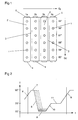
- FIG. 1 shows a temperature control device according to the invention with a total of 24 Prohen 1, which are indicated as circles. It can be liquid filled wells in the device or in corresponding Wells of the device are thermally conductive receptacles that contain the reaction samples contain. The samples are in four columns and six rows in one rectangular grid arranged. The device is divided into four columns Groups in the form of blocks 2 divided against each other with insulating layers 3 are thermally insulated. The groups can also be different from columns be arranged, for example in rectangular, several reaction samples each contained blocks or the like. Also the number of reaction samples a wide range can be varied per row and column.
- heating devices 4 and 5 are arranged in thermally conductive contact, which generate a temperature gradient G T in each of the blocks 2 made of thermally conductive material, which in addition to the illustration as an arrow and with temperature information for the individual lines of reaction samples 1 is shown.
- the heating devices 4, 5 are from the temperature control device in a manner not shown in terms of time and the temperatures to be set controlled that the samples go through a cycle which in one example is shown in FIG 2 is shown.
- all the heating devices 4, 5 are controlled in such a way that all the samples with the same temperature on a ramp 6 up to denaturation level 7 heated at about 90 ° and held at this for a few seconds. thereupon by controlling the heating devices 4, 5 accordingly a ramp 8 cooled down to the annealing stage 9 at about 55 °, which in turn is held for a few seconds. Then it goes up via a ramp 10 the elongation level 11 of 70 °, which is held for some time. Then follows ramp 6 again and the cycle is repeated.
- the samples as shown in Figures 1 and 2, in four groups on the Annealing level for different times of one second, two seconds, held for three seconds.
- the four blocks 2 for held different times at the temperature of the annealing stage by appropriate time control of the heating devices 4, 5.
- the residence time would be 1 for all reaction samples be the same at annealing level 9 and again e.g. at the denaturation level 7 the time difference can be compensated.
- the temperature gradient G T shown in FIG. 1 is used for this purpose, which is applied in addition to the applied time gradient G t , in the case shown at the annealing stage 9. This is also shown in dashed lines in FIG. It can be seen that (dashed lines) six different temperatures are possible for the annealing stage 9, as they result from the temperature gradient in FIG. 1 in the six lines. As FIG. 2 also shows, all combinations of different residence times and different temperatures are possible.
- samples 1 can also be used, for example Individual heating and mutual thermal insulation. she can then be tempered differently in any arrangement and with different Residence times are operated.
- stage temperatures shown in Figure 2 are only given as examples. Depending on the reaction, the stage temperatures can can be chosen very differently. Also the step times shown in the range of a few seconds, depending on a very wide range if necessary, are changed.
Abstract
Description
Die Erfindung betrifft eine Vorrichtung der im Oberbegriff des Anspruches 1
genannten Art.The invention relates to a device in the preamble of
Derartige Vorrichtungen dienen zur Durchführung chemischer Reaktionen in Reaktionsproben, die nacheinander unterschiedliche Temperaturstufen erfordern, welche in aufeinanderfolgend wiederholten Zyklen durchgeführt werden. Insbesondere werden solche Vorrichtungen zur Durchführung der PCR (Polymerase Chain Reaction) benötigt, mit der DNA-Abschnitte amplifiziert werden und zwar beispielsweise mit drei aufeinanderfolgenden Temperaturstufen, nämlich der Denaturierungsstufe, der Annealingstufe und der Elongationsstufe. Dabei hängen die Reaktionsergebnisse wie z.B. Ausbeute und Trennschärfe von den Reaktionsparametern wie z.B. Temperatur, Zeit etc. ab, welche in Versuchen optimiert werden müssen.Devices of this type are used to carry out chemical reactions in reaction samples, that require different temperature levels one after the other, which are carried out in successively repeated cycles. In particular are such devices for carrying out the PCR (polymerase Chain Reaction) with which DNA sections are amplified for example with three successive temperature levels, namely the denaturation level, the annealing level and the elongation level. Hang there the reaction results such as Yield and selectivity from the reaction parameters such as. Temperature, time etc., which is optimized in experiments Need to become.
Solche Vorrichtungen können zur Untersuchung einzelner Reaktionsproben verwendet werden, wobei die Reaktionsparameter der PCR noch unbekannt sind und ermittelt werden sollen. Sie können insbesondere auch zur gleichzeitigen Behandlung einer größeren Zahl von Reaktionsproben vorgesehen sein, wozu jedoch zuvor die Reaktionsparameter in Vorversuchen optimiert werden müssen.Such devices can be used to examine individual reaction samples the reaction parameters of the PCR are still unknown and should be determined. In particular, they can also be used for simultaneous treatment a larger number of reaction samples can be provided, but for what the reaction parameters must be optimized in preliminary tests beforehand.
Die Stufentemperaturen können äußerst kritisch sein. Um die für eine Stufe optimale Temperatur zeitsparend ermitteln zu können, ist eine gattungsgemäße Vorrichtung aus der DE 196 46 155 C2 bekannt, bei der in einem Durchlauf die Proben auf einer oder mehreren Stufen mit unterschiedlichen Temperaturen im Bereich der Stufentemperatur behandelt werden können. Bei anschließender Auswertung der sich für die unterschiedlichen Temperaturen innerhalb einer Temperaturstufe ergebenden Reaktionsergebnisse kann die optimale Stufentemperatur ermittelt werden. Dazu ist mit solchen Vorrichtungen nur ein Durchlauf erforderlich.The stage temperatures can be extremely critical. To get the optimal one level To be able to determine temperature in a time-saving manner is a generic device known from DE 196 46 155 C2, in which the samples in one pass on one or more levels with different temperatures in the range the step temperature can be treated. With subsequent evaluation which is for the different temperatures within a temperature level Resulting reaction results can be the optimal step temperature be determined. With such devices, only one pass is required for this.
Aus der WO 97/46707 ist eine Vorrichtung bekannt, die es ermöglicht, mit unterschiedlichen, insbesondere sehr kurzen Zykluszeiten zu arbeiten. Damit werden auch die Stufenzeiten, also die Verweilzeiten der Proben auf bestimmten Stufen variiert. Alle Proben werden hierbei stets gleich behandelt. Soll mit dieser Konstruktion eine optimale Stufenzeit ermittelt werden, so sind hierzu sind mehrere Durchläufe, also ein erheblicher Aufwand an Zeit und Proben erforderlich.From WO 97/46707 a device is known which makes it possible to work with different particularly short cycle times. With that also the step times, i.e. the dwell times of the samples at certain steps varied. All samples are always treated the same. Should with this construction an optimal step time can be determined, there are several for this Runs, i.e. a considerable amount of time and samples required.
Die Aufgabe der vorliegenden Erfindung besteht darin, eine Vorrichtung der gattungsgemäßen Art zu schaffen, die eine verbesserte Optimierung der Stufenzeiten ermöglicht.The object of the present invention is a device of Generic type to create an improved optimization of step times allows.
Diese Aufgabe wird erfindungsgemäß mit den Merkmalen des Anspruches 1 gelöst. This object is achieved with the features of
Die erfindungsgemäße Vorrichtung behandelt in einem Durchlauf die Proben unterschiedlicher Gruppen, denen jeweils eine oder mehrere Reaktionsproben angehören, mit unterschiedlichen Stufenzeiten und ermöglicht somit die Ermittlung der optimalen Stufenzeit einer oder ggf. auch mehrerer Temperaturstufen. Es hat sich herausgestellt, daß auch die Stufenzeit ein wesentlicher Reaktionsparameter bei bestimmten Stufentemperaturen sein kann, der in erheblichem Maße die Reaktionsergebnisse beeinflußt. Im Gegensatz zu der vorgenannten bekannten Konstruktion, die die Zykluszeiten aller Proben gleich verändert und zur Optimierung der Stufenzeit mehrere Durchläufe benötigt, kann die optimale Stufenzeit mit der Erfindung in einem einzigen Durchlauf, also wesentlich rationeller hinsichtlich Laborzeit und Probenverbrauch ermittelt werden. Die Vorrichtung kann selbstverständlich auch unter Einstellung gleicher Stufenzeiten für alle Gruppen auf eine vorermittelte optimale Stufenzeit zur Massenverarbeitung verwendet werden. Es können die Stufenzeiten bei nur einer Stufe verändert werden oder auch bei allen Stufen.The device according to the invention treats the samples in one pass different groups, each with one or more reaction samples belong, with different step times and thus enables the determination the optimal step time of one or possibly several temperature steps. It it has been found that the step time is also an essential reaction parameter at certain step temperatures can be, to a considerable extent the reaction results are affected. In contrast to the aforementioned known Construction that changes the cycle times of all samples equally and for optimization If the step time requires several runs, the optimal step time can be with the invention in a single pass, so much more efficient with regard to laboratory time and sample consumption. The device can of course also by setting the same step times for everyone Groups used on a pre-determined optimal step time for mass processing become. The step times can be changed for only one step or at all levels.
Werden die Stufenzeiten bei einer oder mehreren Stufen variiert, so ergeben sich
zwischen den Gruppen von Proben unterschiedliche Zykluszeiten, so daß bei
mehrfacher Zykluswiederholung in einem Durchlauf die Proben der unterschiedlichen
Gruppen immer weiter auseinanderlaufend asynchron sind. Dies kann
Nachteile mit sich bringen insbesondere hinsichtlich dann auftretender sehr großer
Temperaturunterschiede zwischen den Gruppen. Vorteilhaft sind daher die
Merkmale des Anspruches 2 vorgesehen. Hiermit kann die Änderung der Stufenzeit
bei einer Stufe durch entsprechende Änderung der Stufenzeit bei einer anderen
Stufe ausgeglichen werden, so daß die Zykluszeit konstant bleibt, also alle
Proben der unterschiedlichen Gruppen in synchronem Zyklus laufen. Temperaturabweichungen
zwischen den Gruppen treten dann nur kurzzeitig auf und insbesondere
in allen Zyklen immer wieder zur selben Zeit, so daß sich über die
Dauer des Durchlaufes konstante Bedingungen einstellen. Dadurch werden die
Ergebnisse eindeutig auswertbar. Die andere in der Verweilzeit zu variierende
Stufe ist vorzugsweise eine Stufe, die keine wesentliche Zeitabhängigkeit aufweist.If the step times are varied for one or more steps, the result is
different cycle times between the groups of samples, so that at
multiple cycle repetition in one pass the samples of different
Groups are increasingly asynchronous. This can
There are disadvantages, particularly with regard to the very large ones that then occur
Temperature differences between the groups. The are therefore advantageous
Features of
Vorteilhaft sind die Merkmale des Anspruches 3 vorgesehen. Hiermit ist es möglich,
in einem Durchlauf nicht nur die optimale Stufenzeit sondern auch die optimale
Stufentemperatur zu ermitteln. Da zwischen den Gruppen die Zeiten und
innerhalb der Gruppen die Temperaturen geändert werden, die beiden Parameter
Zeit und Temperatur also unabhängig von einander geändert werden, können bei
Ermittlung einer Probe mit optimalem Ergebnis durch deren Zuordnung in eine
der Gruppen die optimale Zeit und durch Ermittlung ihrer Lage in der Gruppe die
optimale Temperatur bestimmt werden. Dabei werden vorteilhaft gemäß Anspruch
4 Zeit und Temperatur bei derselben Stufe variiert, z.B. bei der Annealingstufe,
um diese hinsichtlich beider Parameter zu optimieren. Bei den anderen
Stufen können für alle Proben gleiche Temperaturen und konstante Zeiten gewählt
werden.The features of
Durch die unterschiedlichen Verweilzeiten der verschiedenen Gruppen kann es
zu erheblichen Temperaturunterschieden zwischen diesen kommen. Befindet sich
beispielsweise die eine Gruppe bereits auf der Annealingtemperatur von etwa
55°, so kann eine benachbarte Gruppe noch in der Mitte der Rampe zwischen
Denaturierungstemperatur und Annealingtemperatur sein, also bei z.B. 70°. Vorteilhaft
sind daher die Merkmale des Anspruches 5 vorgesehen, womit störende
thermische Beeinflussungen zwischen den Gruppen vermieden werden.Due to the different dwell times of the different groups, it can
there are significant temperature differences between them. Is located
for example, the one group already at the annealing temperature of about
55 °, an adjacent group can still be in the middle of the ramp between
Denaturation temperature and annealing temperature, i.e. at e.g. 70 °. Advantageous
the features of
Vorteilhaft sind die Merkmale des Anspruches 6 vorgesehen. Es sind in Spalten
(oder Zeilen) angeordnete Proben jeweils auf einer Temperiereinrichtung vorgesehen,
die über die Spalte hinweg einen Temperaturgradienten erzeugt. Die
Spalten sind gegeneinander thermisch isoliert und werden mit unterschiedlichen
Zeiten gefahren. Eine solche Vorrichtung zeichnet sich durch große technische
Einfachheit aus und kann im wesentlichen von aus dem Stand der Technik bekannten
Konstruktionsprinzipien Gebrauch machen.The features of
Die erfindungsgemäße Vorrichtung kann vorteilhaft gemäß Anspruch 7 mit Einzelheizung gegeneinander thermisch isolierter Proben ausgebildet sein. Dann lassen sich die Gruppenzuordnungen der Proben beliebig legen. Die Proben einer Gruppe müssen nicht zusammenhängend nebeneinander angeordnet sein. Auch größere Temperaturunterschiede zwischen benachbarten Proben lassen sich problemlos einstellen.The device according to the invention can advantageously with individual heating samples thermally insulated from one another. Then leave the group assignments of the samples are arbitrary. The samples one Groups do not have to be arranged side by side. Also larger temperature differences between neighboring samples can be easily to adjust.
In der Zeichnung ist die Erfindung beispielsweise und schematisch dargestellt. Es zeigen:
Figur 1- in Draufsicht eine erfindungsgemäße Vorrichtung gemäß
Anspruch 6 und Figur 2- in einem Temperatur-/Zeitdiagramm einen mit der Vorrichtung
der
Figur 1 erzeugbaren Zyklus.
- Figure 1
- in plan view an inventive device according to
claim 6 and - Figure 2
- in a temperature / time diagram a cycle that can be generated with the device of FIG. 1.
Figur 1 zeigt eine erfindungsgemäße Temperiervorrichtung mit insgesamt 24
Prohen 1, die als Kreise angedeutet sind. Es kann sich hierbei um mit Flüssigkeit
gefüllte Vertiefungen in der Vorrichtung handeln oder um in entsprechenden
Vertiefungen der Vorrichtung wärmeleitend aufgenommene Gefäße, die die Reaktionsproben
enthalten. Die Proben sind in vier Spalten und sechs Zeilen in einem
rechtwinkeligen Gitter angeordnet. Die Vorrichtung ist spaltenweise in vier
Gruppen in Form von Blöcken 2 unterteilt, die gegeneinander mit Isolierschichten
3 thermisch isoliert sind. Die Gruppen können auch anders als spaltenweise
angeordnet sein, beispielsweise in rechteckigen, jeweils mehrere Reaktionsproben
enthaltenen Blöcken oder dergleichen. Auch die Anzahl der Reaktionsproben
pro Zeile und Spalte kann in weitem Umfang variiert werden.FIG. 1 shows a temperature control device according to the invention with a total of 24
An den Spaltenenden, also an den Längsenden der Blöcke 2, sind jeweils Heizeinrichtung
4 und 5 in wärmeleitendem Kontakt angeordnet, die in jedem der
aus thermisch leitfähigem Material ausgebildeten Blöcke 2 einen Temperaturgradienten
GT erzeugen, der neben der Abbildung als Pfeil und mit Temperaturangaben
für die einzelnen Zeilen von Reaktionsproben 1 dargestellt ist.At the column ends, i.e. at the longitudinal ends of the
Die Heizeinrichtungen 4, 5 sind in nicht dargestellter Weise von der Temperiervorrichtung
zeitlich und hinsichtlich der einzustellenden Temperaturen derart
gesteuert, daß die Proben einen Zyklus durchlaufen, der in einem Beispiel in Figur
2 dargestellt ist.The
Zunächst sind alle Heizeinrichtungen 4, 5 heizend derart gesteuert, daß alle Proben
mit gleicher Temperatur auf einer Rampe 6 bis auf die Denaturierungsstufe 7
bei etwa 90° geheizt und bei dieser für einige Sekunden gehalten werden. Sodann
werden sie durch entsprechende Steuerung der Heizeinrichtungen 4, 5 entlang
einer Rampe 8 abgekühlt bis auf die Annealingstufe 9 bei etwa 55°, die wiederum
für einige Sekunden gehalten wird. Anschließend geht es über eine Rampe 10 auf
die Elongationsstufe 11 von 70°, die für einige Zeit gehalten wird. Dann folgt
wieder die Rampe 6 und der Zyklus wird von neuem durchlaufen.First of all, all the
Bei der vorstehenden Beschreibung wurde in Figur 2 auf die durchgezogene Linie
Bezug genommen. Der dargestellte Zyklus sieht für alle Proben 1 stets dieselben
Temperaturen und Verweilzeiten auf den Stufen vor. Es handelt sich hierbei
um den Modus der Temperiervorrichtung für die Massenverarbeitung vieler Proben,
wobei alle Proben gleich behandelt werden. In the above description, the solid line in FIG
Referred. The cycle shown always sees the same for all
Soll bei der Annealingstufe 9 die optimale Verweilzeit ermittelt werden, so werden
die Proben, wie in den Figuren 1 und 2 dargestellt, in vier Gruppen auf der
Annealingstufe für unterschiedliche Zeiten von einer Sekunde, zwei Sekunden,
drei Sekunden gehalten. Dazu werden, wie Figur 1 zeigt, die vier Blöcke 2 für
unterschiedliche Zeit auf der Temperatur der Annealingstufe gehalten und zwar
durch entsprechende zeitliche Ansteuerung der Heizeinrichtungen 4, 5.If the optimal dwell time is to be determined at annealing
Würde man nur die Verweilzeit bei auf der Annealingstufe 9 ändern und dabei
die Rampen 6, 8, 10 und die Verweilzeiten bei der Denaturierungsstufe 7 und der
Elongationsstufe 11 beibehalten, so würden sich für die vier Gruppen von Proben
1 in den vier Blöcken 2 unterschiedliche Zykluszeiten ergeben. Um dies zu vermeiden,
werden die Verweilzeiten im dargestellten Ausführungsbeispiel bei der
Denaturierungsstufe 7 entsprechend angepaßt, so daß die Zykluszeit konstant
bleibt. Dies ist in Figur 2 dargestellt.Would you just change the dwell time at
Wie Figur 2 zeigt, sind zu der Rampe 8 drei parallele Rampen (gestrichelt) dargestellt.
Diese entsprechen um jeweils denselben Zeitraum verlängerten Verweilzeiten
auf der Denaturierungsstufe 7 und entsprechend verkürzten Verweilzeiten
auf der Annealingstufe 9. Ersichtlich bleibt dabei die Zykluszeit konstant, so daß
bei dem immer wieder durchlaufenden Zyklus stets dieselben Verhältnisse herrschen
und die unterschiedlichen Gruppen (Blöcke 2) nicht immer weiter hinsichtlich
ihrer Temperaturbehandlung auseinanderlaufen.As Figure 2 shows, three parallel ramps (dashed) are shown to the
Soll z.B. die Auswirkung der Verweilzeit auf der Elongationsstufe 11 auf das
Reaktionsergebnis ermittelt werden, so kann entsprechend wie vorstehend für die
Annealingstufe 9 erläutert, mit unterschiedlichen Zeiten bei der Elongationsstufe
11 gearbeitet werden. Dabei würde für alle Reaktionsproben 1 die Verweilzeit
bei der Annealingstufe 9 gleich sein und es könnte wiederum z.B. bei der Denaturierungsstufe
7 die Zeitverschiebung ausgeglichen werden. Should e.g. the effect of the dwell time on the
Zusätzlich zur Behandlung der Proben mit unterschiedlichen Verweilzeiten, können die Proben auch mit unterschiedlichen Temperaturen im Bereich einer der Stufentemperaturen behandelt werden, um nicht nur die Zeitabhängigkeit sondern auch die Temperaturabhängigkeit des Reaktionsergebnisses für eine Stufe ermitteln zu können.In addition to treating the samples with different retention times, you can the samples also with different temperatures in the range of one Step temperatures are treated to not only the time dependence but also determine the temperature dependence of the reaction result for one stage to be able to.
Dazu dient der in Figur 1 dargestellte Temperaturgradient GT, der neben dem
angelegten Zeitgradienten Gt, und zwar im dargestellten Fall bei der Annealingstufe
9, angelegt ist. Auch dies ist in Figur 2 gestrichelt dargestellt. Man erkennt,
daß (gestrichelt) sechs unterschiedliche Temperaturen für die Annealingstufe 9
möglich sind, wie sie sich aus dem Temperaturgradienten in Figur 1 in den sechs
Zeilen ergeben. Wie Figur 2 ferner zeigt, sind alle Kombinationen unterschiedlicher
Verweilzeiten und unterschiedlicher Temperaturen möglich.The temperature gradient G T shown in FIG. 1 is used for this purpose, which is applied in addition to the applied time gradient G t , in the case shown at the
Wird bei Auswertung der Reaktionsergebnisse aller Proben z.B. gefunden, daß die in Figur 1 mit einem Unterstrich markierte Probe in der dritten Spalte und der fünften Zeile ein optimales Ergebnis liefert, so steht fest, daß sich daraus im dargestellten Beispiel für die Annealingstufe 9 eine Verweilzeit von drei Sekunden und eine Temperatur von 59° als Optimum ergibt.Is used when evaluating the reaction results of all samples e.g. found that the sample marked with an underscore in FIG. 1 in the third column and the fifth line provides an optimal result, it is clear that this results in the Example for annealing level 9 a dwell time of three seconds and results in a temperature of 59 ° as an optimum.
Anders als in Figur 1 dargestellt, können die Proben 1 beispielsweise auch mit
Einzelheizung und gegenseitiger thermischer Isolierung ausgebildet sein. Sie
können dann in beliebiger Anordnung unterschiedlich temperiert und mit unterschiedlichen
Verweilzeiten betrieben werden.Unlike shown in FIG. 1, the
In dem in Figur 2 dargestellten Zyklusbeispiel wird mit drei Temperaturstufen gearbeitet. Bei anderen Reaktionen kann auch z.B. mit nur zwei Stufen oder mit mehr als drei Stufen gearbeitet werden. Die in Figur 2 dargestellten Stufentemperaturen sind nur beispielhaft angegeben. Je nach Reaktion können die Stufentemperaturen sehr unterschiedlich gewählt werden. Auch die dargestellten Stufenzeiten im Bereich weniger Sekunden können in einem sehr weiten Rahmen, je nach Gegebenheit, geändert werden.In the cycle example shown in Figure 2 with three temperature levels worked. For other reactions, e.g. with only two steps or with more than three levels can be worked. The stage temperatures shown in Figure 2 are only given as examples. Depending on the reaction, the stage temperatures can can be chosen very differently. Also the step times shown in the range of a few seconds, depending on a very wide range if necessary, are changed.
Claims (7)
Applications Claiming Priority (2)
| Application Number | Priority Date | Filing Date | Title |
|---|---|---|---|
| DE10105127 | 2001-02-05 | ||
| DE10105127 | 2001-02-05 |
Publications (3)
| Publication Number | Publication Date |
|---|---|
| EP1228804A2 true EP1228804A2 (en) | 2002-08-07 |
| EP1228804A3 EP1228804A3 (en) | 2003-11-19 |
| EP1228804B1 EP1228804B1 (en) | 2005-11-23 |
Family
ID=7672893
Family Applications (1)
| Application Number | Title | Priority Date | Filing Date |
|---|---|---|---|
| EP01121967A Expired - Lifetime EP1228804B1 (en) | 2001-02-05 | 2001-09-13 | Device for tempering reaction samples |
Country Status (3)
| Country | Link |
|---|---|
| EP (1) | EP1228804B1 (en) |
| AT (1) | ATE310584T1 (en) |
| DE (1) | DE50108159D1 (en) |
Cited By (1)
| Publication number | Priority date | Publication date | Assignee | Title |
|---|---|---|---|---|
| EP1269171A1 (en) * | 2000-03-07 | 2003-01-02 | Northeastern University | Parallel array of independent thermostats for column separations |
Citations (4)
| Publication number | Priority date | Publication date | Assignee | Title |
|---|---|---|---|---|
| WO1998020975A1 (en) * | 1996-11-08 | 1998-05-22 | Eppendorf-Netheler-Hinz Gmbh | Temperature-regulating block with temperature-regulating devices |
| US5819842A (en) * | 1991-12-05 | 1998-10-13 | Potter; Derek Henry | Method and apparatus for temperature control of multiple samples |
| US6106784A (en) * | 1997-09-26 | 2000-08-22 | Applied Chemical & Engineering Systems, Inc. | Thawing station |
| WO2001024930A1 (en) * | 1999-10-01 | 2001-04-12 | Mwg-Biotech Ag | Device for carrying out chemical or biological reactions |
-
2001
- 2001-09-13 DE DE50108159T patent/DE50108159D1/en not_active Expired - Lifetime
- 2001-09-13 EP EP01121967A patent/EP1228804B1/en not_active Expired - Lifetime
- 2001-09-13 AT AT01121967T patent/ATE310584T1/en not_active IP Right Cessation
Patent Citations (4)
| Publication number | Priority date | Publication date | Assignee | Title |
|---|---|---|---|---|
| US5819842A (en) * | 1991-12-05 | 1998-10-13 | Potter; Derek Henry | Method and apparatus for temperature control of multiple samples |
| WO1998020975A1 (en) * | 1996-11-08 | 1998-05-22 | Eppendorf-Netheler-Hinz Gmbh | Temperature-regulating block with temperature-regulating devices |
| US6106784A (en) * | 1997-09-26 | 2000-08-22 | Applied Chemical & Engineering Systems, Inc. | Thawing station |
| WO2001024930A1 (en) * | 1999-10-01 | 2001-04-12 | Mwg-Biotech Ag | Device for carrying out chemical or biological reactions |
Cited By (3)
| Publication number | Priority date | Publication date | Assignee | Title |
|---|---|---|---|---|
| EP1269171A1 (en) * | 2000-03-07 | 2003-01-02 | Northeastern University | Parallel array of independent thermostats for column separations |
| EP1269171A4 (en) * | 2000-03-07 | 2003-04-02 | Univ Northeastern | Parallel array of independent thermostats for column separations |
| US6929731B2 (en) | 2000-03-07 | 2005-08-16 | Northeastern University | Parallel array of independent thermostats for column separations |
Also Published As
| Publication number | Publication date |
|---|---|
| DE50108159D1 (en) | 2005-12-29 |
| EP1228804A3 (en) | 2003-11-19 |
| EP1228804B1 (en) | 2005-11-23 |
| ATE310584T1 (en) | 2005-12-15 |
Similar Documents
| Publication | Publication Date | Title |
|---|---|---|
| EP1054735B1 (en) | Miniaturized temperature-zone flow reactor | |
| EP0881950B1 (en) | Temperature-regulating block with temperature-regulating devices | |
| EP1216098B1 (en) | Device for carrying out chemical or biological reactions | |
| DE4024714C2 (en) | Apparatus for repeated, automatic execution of a heat treatment cycle for the treatment of a sample | |
| DE19646115C2 (en) | Use of temperature control devices for temperature control of a temperature control block | |
| DE1900279C3 (en) | Incubator for an automatic chemical analyzer | |
| EP0936945B1 (en) | Temperature-regulating block with receivers | |
| DE69923912T2 (en) | Pulsed electric field treatment chamber with integrated modular design | |
| DE60012817T2 (en) | Improved titration plates | |
| EP1140343B1 (en) | Method and device for the convective movement of liquids in microsystems | |
| EP0731732A1 (en) | Miniaturized flow thermocycler | |
| DE19859459A1 (en) | Microsystems for cell permeation and fusion | |
| EP0718038A2 (en) | Apparatus for separating mixtures of microscopic small dielectric particles dispersed in a fluid or a gel | |
| DE10221763A1 (en) | Thermal cycler with temperature control block controlled in cycles | |
| DE2526117A1 (en) | ELECTRO-OPTICAL SWITCH AND METHOD OF ITS MANUFACTURING | |
| EP0751827B1 (en) | Method of processing nucleic acids | |
| DE102010043030A1 (en) | Micro-fluidic device for processing bioparticles e.g. DNA, comprises heating devices that are located above and below chamber in which interdigitated electrodes are provided | |
| DE2913331C2 (en) | Extraction column | |
| EP1228804B1 (en) | Device for tempering reaction samples | |
| EP1214978B1 (en) | Method of heating samples at multiple temperatures in a laboratory thermal conditioning device | |
| EP2331260B1 (en) | Device for thermally regulating a rotationally symmetrical container | |
| DE10062890A1 (en) | Laboratory temperature control device for temperature control of reaction samples | |
| DE20221055U1 (en) | Thermocycler for amplifying nucleic acid stretches in probe, comprises temperature controlling block that is sub-divided into segments each receiving specimens and are thermally separated and are controlled separately | |
| DE19646114B4 (en) | Laboratory thermostat with temperature blocks | |
| DE102005044021A1 (en) | Laboratory tempering device with top |
Legal Events
| Date | Code | Title | Description |
|---|---|---|---|
| PUAI | Public reference made under article 153(3) epc to a published international application that has entered the european phase |
Free format text: ORIGINAL CODE: 0009012 |
|
| AK | Designated contracting states |
Kind code of ref document: A2 Designated state(s): AT BE CH CY DE DK ES FI FR GB GR IE IT LI LU MC NL PT SE TR |
|
| AX | Request for extension of the european patent |
Free format text: AL;LT;LV;MK;RO;SI |
|
| PUAL | Search report despatched |
Free format text: ORIGINAL CODE: 0009013 |
|
| AK | Designated contracting states |
Kind code of ref document: A3 Designated state(s): AT BE CH CY DE DK ES FI FR GB GR IE IT LI LU MC NL PT SE TR |
|
| AX | Request for extension of the european patent |
Extension state: AL LT LV MK RO SI |
|
| 17P | Request for examination filed |
Effective date: 20040110 |
|
| 17Q | First examination report despatched |
Effective date: 20040317 |
|
| AKX | Designation fees paid |
Designated state(s): AT BE CH CY DE DK ES FI FR GB GR IE IT LI LU MC NL PT SE TR |
|
| GRAP | Despatch of communication of intention to grant a patent |
Free format text: ORIGINAL CODE: EPIDOSNIGR1 |
|
| GRAS | Grant fee paid |
Free format text: ORIGINAL CODE: EPIDOSNIGR3 |
|
| GRAA | (expected) grant |
Free format text: ORIGINAL CODE: 0009210 |
|
| AK | Designated contracting states |
Kind code of ref document: B1 Designated state(s): AT BE CH CY DE DK ES FI FR GB GR IE IT LI LU MC NL PT SE TR |
|
| PG25 | Lapsed in a contracting state [announced via postgrant information from national office to epo] |
Ref country code: NL Free format text: LAPSE BECAUSE OF FAILURE TO SUBMIT A TRANSLATION OF THE DESCRIPTION OR TO PAY THE FEE WITHIN THE PRESCRIBED TIME-LIMIT Effective date: 20051123 Ref country code: IT Free format text: LAPSE BECAUSE OF FAILURE TO SUBMIT A TRANSLATION OF THE DESCRIPTION OR TO PAY THE FEE WITHIN THE PRESCRIBED TIME-LIMIT;WARNING: LAPSES OF ITALIAN PATENTS WITH EFFECTIVE DATE BEFORE 2007 MAY HAVE OCCURRED AT ANY TIME BEFORE 2007. THE CORRECT EFFECTIVE DATE MAY BE DIFFERENT FROM THE ONE RECORDED. Effective date: 20051123 Ref country code: IE Free format text: LAPSE BECAUSE OF FAILURE TO SUBMIT A TRANSLATION OF THE DESCRIPTION OR TO PAY THE FEE WITHIN THE PRESCRIBED TIME-LIMIT Effective date: 20051123 Ref country code: FI Free format text: LAPSE BECAUSE OF FAILURE TO SUBMIT A TRANSLATION OF THE DESCRIPTION OR TO PAY THE FEE WITHIN THE PRESCRIBED TIME-LIMIT Effective date: 20051123 |
|
| REG | Reference to a national code |
Ref country code: GB Ref legal event code: FG4D Free format text: NOT ENGLISH |
|
| REG | Reference to a national code |
Ref country code: CH Ref legal event code: EP |
|
| REF | Corresponds to: |
Ref document number: 50108159 Country of ref document: DE Date of ref document: 20051229 Kind code of ref document: P |
|
| REG | Reference to a national code |
Ref country code: IE Ref legal event code: FG4D Free format text: LANGUAGE OF EP DOCUMENT: GERMAN |
|
| PG25 | Lapsed in a contracting state [announced via postgrant information from national office to epo] |
Ref country code: DK Free format text: LAPSE BECAUSE OF FAILURE TO SUBMIT A TRANSLATION OF THE DESCRIPTION OR TO PAY THE FEE WITHIN THE PRESCRIBED TIME-LIMIT Effective date: 20060223 Ref country code: GR Free format text: LAPSE BECAUSE OF FAILURE TO SUBMIT A TRANSLATION OF THE DESCRIPTION OR TO PAY THE FEE WITHIN THE PRESCRIBED TIME-LIMIT Effective date: 20060223 Ref country code: SE Free format text: LAPSE BECAUSE OF FAILURE TO SUBMIT A TRANSLATION OF THE DESCRIPTION OR TO PAY THE FEE WITHIN THE PRESCRIBED TIME-LIMIT Effective date: 20060223 |
|
| PG25 | Lapsed in a contracting state [announced via postgrant information from national office to epo] |
Ref country code: ES Free format text: LAPSE BECAUSE OF FAILURE TO SUBMIT A TRANSLATION OF THE DESCRIPTION OR TO PAY THE FEE WITHIN THE PRESCRIBED TIME-LIMIT Effective date: 20060306 |
|
| GBT | Gb: translation of ep patent filed (gb section 77(6)(a)/1977) |
Effective date: 20060222 |
|
| PG25 | Lapsed in a contracting state [announced via postgrant information from national office to epo] |
Ref country code: PT Free format text: LAPSE BECAUSE OF FAILURE TO SUBMIT A TRANSLATION OF THE DESCRIPTION OR TO PAY THE FEE WITHIN THE PRESCRIBED TIME-LIMIT Effective date: 20060424 |
|
| NLV1 | Nl: lapsed or annulled due to failure to fulfill the requirements of art. 29p and 29m of the patents act | ||
| ET | Fr: translation filed | ||
| REG | Reference to a national code |
Ref country code: IE Ref legal event code: FD4D |
|
| PLBE | No opposition filed within time limit |
Free format text: ORIGINAL CODE: 0009261 |
|
| STAA | Information on the status of an ep patent application or granted ep patent |
Free format text: STATUS: NO OPPOSITION FILED WITHIN TIME LIMIT |
|
| PG25 | Lapsed in a contracting state [announced via postgrant information from national office to epo] |
Ref country code: BE Free format text: LAPSE BECAUSE OF NON-PAYMENT OF DUE FEES Effective date: 20060930 Ref country code: MC Free format text: LAPSE BECAUSE OF NON-PAYMENT OF DUE FEES Effective date: 20060930 Ref country code: CH Free format text: LAPSE BECAUSE OF NON-PAYMENT OF DUE FEES Effective date: 20060930 Ref country code: LI Free format text: LAPSE BECAUSE OF NON-PAYMENT OF DUE FEES Effective date: 20060930 |
|
| 26N | No opposition filed |
Effective date: 20060824 |
|
| REG | Reference to a national code |
Ref country code: CH Ref legal event code: PL |
|
| PG25 | Lapsed in a contracting state [announced via postgrant information from national office to epo] |
Ref country code: AT Free format text: LAPSE BECAUSE OF NON-PAYMENT OF DUE FEES Effective date: 20060913 |
|
| BERE | Be: lapsed |
Owner name: EPPENDORF A.G. Effective date: 20060930 |
|
| PG25 | Lapsed in a contracting state [announced via postgrant information from national office to epo] |
Ref country code: TR Free format text: LAPSE BECAUSE OF FAILURE TO SUBMIT A TRANSLATION OF THE DESCRIPTION OR TO PAY THE FEE WITHIN THE PRESCRIBED TIME-LIMIT Effective date: 20051123 Ref country code: LU Free format text: LAPSE BECAUSE OF NON-PAYMENT OF DUE FEES Effective date: 20060913 |
|
| PG25 | Lapsed in a contracting state [announced via postgrant information from national office to epo] |
Ref country code: CY Free format text: LAPSE BECAUSE OF FAILURE TO SUBMIT A TRANSLATION OF THE DESCRIPTION OR TO PAY THE FEE WITHIN THE PRESCRIBED TIME-LIMIT Effective date: 20051123 |
|
| REG | Reference to a national code |
Ref country code: DE Ref legal event code: R082 Ref document number: 50108159 Country of ref document: DE Representative=s name: EISENFUEHR SPEISER PATENTANWAELTE RECHTSANWAEL, DE Ref country code: DE Ref legal event code: R082 Ref document number: 50108159 Country of ref document: DE Representative=s name: MEISSNER BOLTE & PARTNER GBR, DE Ref country code: DE Ref legal event code: R082 Ref document number: 50108159 Country of ref document: DE Representative=s name: MEISSNER BOLTE PATENTANWAELTE RECHTSANWAELTE P, DE |
|
| REG | Reference to a national code |
Ref country code: FR Ref legal event code: PLFP Year of fee payment: 16 |
|
| REG | Reference to a national code |
Ref country code: FR Ref legal event code: PLFP Year of fee payment: 17 |
|
| REG | Reference to a national code |
Ref country code: FR Ref legal event code: PLFP Year of fee payment: 18 |
|
| PGFP | Annual fee paid to national office [announced via postgrant information from national office to epo] |
Ref country code: GB Payment date: 20200922 Year of fee payment: 20 Ref country code: FR Payment date: 20200914 Year of fee payment: 20 Ref country code: DE Payment date: 20200925 Year of fee payment: 20 |
|
| REG | Reference to a national code |
Ref country code: DE Ref legal event code: R082 Ref document number: 50108159 Country of ref document: DE Representative=s name: EISENFUEHR SPEISER PATENTANWAELTE RECHTSANWAEL, DE |
|
| REG | Reference to a national code |
Ref country code: DE Ref legal event code: R071 Ref document number: 50108159 Country of ref document: DE |
|
| REG | Reference to a national code |
Ref country code: GB Ref legal event code: PE20 Expiry date: 20210912 |
|
| PG25 | Lapsed in a contracting state [announced via postgrant information from national office to epo] |
Ref country code: GB Free format text: LAPSE BECAUSE OF EXPIRATION OF PROTECTION Effective date: 20210912 |