EP1231137B2 - Tailored wing assembly for an aircraft moveable slat system - Google Patents
Tailored wing assembly for an aircraft moveable slat system Download PDFInfo
- Publication number
- EP1231137B2 EP1231137B2 EP02075572.4A EP02075572A EP1231137B2 EP 1231137 B2 EP1231137 B2 EP 1231137B2 EP 02075572 A EP02075572 A EP 02075572A EP 1231137 B2 EP1231137 B2 EP 1231137B2
- Authority
- EP
- European Patent Office
- Prior art keywords
- slat
- wing assembly
- wing
- cutout
- cavity
- Prior art date
- Legal status (The legal status is an assumption and is not a legal conclusion. Google has not performed a legal analysis and makes no representation as to the accuracy of the status listed.)
- Expired - Lifetime
Links
Images


Classifications
-
- B—PERFORMING OPERATIONS; TRANSPORTING
- B64—AIRCRAFT; AVIATION; COSMONAUTICS
- B64C—AEROPLANES; HELICOPTERS
- B64C9/00—Adjustable control surfaces or members, e.g. rudders
- B64C9/14—Adjustable control surfaces or members, e.g. rudders forming slots
- B64C9/22—Adjustable control surfaces or members, e.g. rudders forming slots at the front of the wing
-
- B—PERFORMING OPERATIONS; TRANSPORTING
- B64—AIRCRAFT; AVIATION; COSMONAUTICS
- B64C—AEROPLANES; HELICOPTERS
- B64C3/00—Wings
- B64C3/38—Adjustment of complete wings or parts thereof
- B64C3/44—Varying camber
- B64C3/50—Varying camber by leading or trailing edge flaps
-
- Y—GENERAL TAGGING OF NEW TECHNOLOGICAL DEVELOPMENTS; GENERAL TAGGING OF CROSS-SECTIONAL TECHNOLOGIES SPANNING OVER SEVERAL SECTIONS OF THE IPC; TECHNICAL SUBJECTS COVERED BY FORMER USPC CROSS-REFERENCE ART COLLECTIONS [XRACs] AND DIGESTS
- Y02—TECHNOLOGIES OR APPLICATIONS FOR MITIGATION OR ADAPTATION AGAINST CLIMATE CHANGE
- Y02T—CLIMATE CHANGE MITIGATION TECHNOLOGIES RELATED TO TRANSPORTATION
- Y02T50/00—Aeronautics or air transport
- Y02T50/40—Weight reduction
Definitions
- the present invention generally relates to aircraft wing assemblies. More particularly, the invention relates to a wing assembly for an aircraft moveable slat system having a contoured surface to improve airflow.
- leading edge of a typical aircraft wing will have an inboard slat as well as a number of outboard slats.
- Leading edge slats are critical to the improvement of the takeoff and landing performance of the aircraft. For example, when the slats extend, they increase the aerodynamic lift of the wing.
- the leading edge slats also function to increase the angle of attack at which the wing stalls.
- a typical moveable slat system for an aircraft wing will include a slat having an outer geometry which defines a leading edge of the aircraft wing, and an actuation mechanism.
- the actuation mechanism is coupled to the slat for positioning the slat with respect to the aircraft.
- the moveable slat system will also have a wing assembly (or Surface-1) positioned immediately adjacent to the slat such the actuation mechanism extends through a cutout of the wing assembly. As will be discussed below, this cutout can be particularly troublesome with regard to aerodynamic lift.
- the region between the slat trailing edge and the edge structure is typically gapped for landing configurations. This provides the largest amount of aerodynamic lift for a given wing area. This gapped region experiences high velocity aerodynamic flows especially during maximum lift conditions.
- the above-discussed cutout is located in a region of the wing where disruptions in the flow field can affect the maximum lift generated by the entire wing. The amount of exposed cutout above the slat trailing edge at landing has therefore been correlated with increased aerodynamic losses.
- the dual pivot design uses a slat position for landing which completely covers the cutout. This approach has been used on various wing designs, and requires an auxiliary track system to obtain the high slat height.
- the auxiliary track system comes at a significant cost. Cost figures have been on the order of $250,000 per aircraft relative to a single pivot slat system (to be described below). It is therefore desirable to provide a moveable slat system that does not require an auxiliary track system in order to minimize the aerodynamic losses associated with the wing assembly cutout.
- the single pivot slat design was developed to provide equivalent aerodynamic performance as the dual pivot design but without the need for an auxiliary track system.
- the single pivot design has a lower slat trailing edge height at landing relative to a dual pivot slat system.
- the lower height exposes a larger amount of cutout to the high velocity air stream which exists above the slat trailing edge on the wing top surface.
- the cutout problem is addressed in this approach with a fully articulating track door system to cover the cutout.
- the doors are expensive due to part count and complexity. Costs on the order of $50,000 per aircraft have been experienced.
- the doors require a fairly large actuating spring to allow closure. This increases forces to the door, thereby requiring a heavier structure.
- the doors slide in tracks with fairly small slots between the door and the track. The slot could be prone to blockage due to heavy icing conditions, especially in the case of glare ice.
- the above-described track door system also has a number of failure modes such as freezing in the up position, or freezing in the down position. When the door system freezes in the down position, retraction can result in breakage. It is also known that both of these failure modes leave the cutout unprotected with a subsequent loss in aerodynamic performance. It is therefore desirable to provide a wing assembly for an aircraft wing moveable slat system that does not have moveable hardware.
- the elimination of moveable hardware would provide a number of unique benefits. For example, the resulting system would be cheaper and more simply manufactured. Furthermore, eliminating the need for actuation improves reliability and setup time.
- US 3,889,903 and US 4,099,691 relate to a boundary layer control system for a leading edge structure of a wing assembly.
- the leading edge structure has a spar to which spaced off jaw-like brackets are secured. Between these pairs of brackets an elongated pressurized air duct is attached.
- the air duct is connected to a plurarity of spanwise-spaced apertures for injecting air into a portion of the boundary layer region.
- this boundary layer control system is applied to a fixed leading edge structure of an airwing, whereas in US 4,099,691 a similar system is used in connection with a movable slat.
- DE 746 714 discloses a wing assembly for an aircraft movable slat system in accordance with the preamble of claim 1. It is an object of the present invention to provide a wing assembly wherein the disadvantages that are associated with the prior designs have been obviated.
- the above and other objectives are provided by a wing assembly for an aircraft moveable slat system in accordance with the present invention.
- the wing assembly has a fixed structure and a contoured surface.
- the fixed structure has an exterior surface defining an external contour and an interior surface defining a cavity.
- the fixed structure also has one or more edges defining a cutout.
- the contoured surface is coupled to one or more of the edges of the cutout and extends into the cavity.
- the contoured surface promotes airflow from the cavity to the external contour.
- a moveable slat system for an aircraft wing has a slat, an actuation mechanism, and a wing assembly.
- the slat has an outer geometry which defines a leading edge of the aircraft wing.
- the actuation mechanism is coupled to the slat for positioning the slat with respect to the aircraft.
- the wing assembly is positioned adjacent to the slat such that the actuation mechanism extends through a tailored cutout of the wing assembly.
- FIG. 1 is a perspective view of a moveable slat system according to one embodiment of the present invention
- FIG. 2 is a side view of the moveable slat system shown in FIG. 1 ;
- FIG. 3 is a plot demonstrating aerodynamic lift performance for the moveable slat system shown in FIGS. 1 and 2 ;
- FIG. 4 is a perspective view of a wing assembly in accordance with one embodiment of the present invention.
- FIG. 5 is a perspective view of a wing assembly in accordance with an alternative embodiment of the present invention.
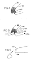
- FIG. 6 is a side view of a wing assembly demonstrating the tailoring profiles shown in FIGS. 4 and 5 ;
- FIG. 7 is a plot demonstrating aerodynamic performance of the wing assemblies shown in FIGS. 4-6 ;
- FIG. 8 is a perspective view of a moveable slat system with an extension cantilevered off a trailing edge of the slat in accordance with the principles of the present invention
- FIG. 9 is a side view of the moveable slat system shown in FIG. 8 ;
- FIG. 10 is a plot demonstrating aerodynamic performance of the moveable slat system shown in FIGS. 8 and 9 .
- the slat system 20 has a slat 22, an actuation mechanism (not shown), and a wing assembly 24.
- the slat 22 has an outer geometry which defines a leading edge of an aircraft wing. While the preferred slat 22 will be described as being an inboard slat, the present invention can be readily applied to outboard slats as well.
- the actuation mechanism is coupled to the slat 22 for positioning the slat 22 with respect to the aircraft. It will be appreciated that the actuation mechanism can be any type of conventional actuation mechanism. Exemplary actuation mechanisms are described in U.S. Patent No. 4,399,970 to Evans , and U.S. Patent No. 5,544,847 to Bliesner .
- the wing assembly 24 is positioned immediately adjacent to the slat 22 such that the actuation mechanism extends through a tailored cutout 26 of the wing assembly 24. Tailoring the cutout 26 represents an improvement over all conventional wing assemblies.
- the tailored cutout 26 provides a low cost fixed hardware device which provides the aerodynamic benefits of a moveable door system at a reduced cost and increased safety.
- aerodynamic testing validates the concept of tailoring and demonstrates the performance differences between the various cutout geometries.
- the slat 22 has an extension 28 cantilevered off of a trailing edge of the slat 22.
- FIG. 3 demonstrates the aerodynamic performance of the preferred embodiment at plot 30. It can be seen that a completely sealed cavity demonstrated by curve 32 results in a maximum coefficient of lift of approximately 2.9. Removing the cutout, however, is not an acceptable solution in many cases due to the need to actuate the slat.
- a high tailored cavity demonstrated by curve 34 results in a nearly identical coefficient of lift for slat angles below 20 degrees. The slat angle ⁇ is measured from horizontal.
- a traditional open cavity demonstrated by curve 36 has a maximum coefficient of lift of about 2.6.
- the cutout can have a profile that is tailored to provide the desired level of aerodynamic performance. Furthermore, the cutout profile demonstrated by curve 34 can provide optimal results when used in conjunction with the slat extension.
- FIG. 4 illustrates a wing assembly 38 having a relatively low tailoring profile.
- the wing assembly 38 has a fixed structure 40 and a contoured surface 42.
- the fixed structure 40 has an exterior surface defining an external contour and an interior surface defining a cavity.
- the fixed structure 40 also has one or more edges defining a cutout.
- the contoured surface 42 is coupled to one or more of the edges of the cutout and extends into the cavity.
- the contoured surface 42 can be coupled to the fixed structure 40 by welding or any other conventional attachment technique.
- FIG. 5 illustrates the high tailoring profile shown in FIG. 1 .
- the higher profile results in less resistance to airflow from the cavity to the external contour and therefore corresponds to less aerodynamic lift than achievable through a lower profile.
- the desired profile is achieved by providing a variable radius shape for the contoured surface 44.
- the variable radius shape has an upper centerline location 46 and side edge locations 48.
- the variable radius shape decreases in radius from the upper centerline location 46 to the side edge locations 48.
- the contoured surface 44 can be tailored to meet the specific aerodynamic requirements of the given application.
- the concept behind the variable radius was developed based on interpretations of the direction of the airflow streamlines emerging from the cutout.
- the air movement is from the high pressure underside of the wing to the low pressure upperside.
- the cutout therefore provides a slot for the air to flow between the two pressure differentials.
- As the air leaves the cavity 50, on the wing upper surface it is rapidly entrained into the main wing airstream.
- the main wing airstream is moving almost perpendicularly to the leading edge at the cutout location.
- the entrainment of the cavity airstream therefore causes the air moving out of the center of the cavity 50 to flow around the tailored shape in an almost perpendicular path.
- a radius of approximately .75 percent wing chord was chosen for the centerline lift based on past experiences with similar high lift flow-fields.
- the radius around the side edges of the contour are varied from the centerline value to zero at the side edge locations 48.
- the rate of radius reduction is preferably based on the flow-field which moves in a helical pattern around the contoured edge for locations away from the centerline.
- the helical radius, over which the air moves, is preferably designed to produce approximately the same effective radius as the centerline perpendicular path.
- plot 56 contains a number of curves including a high tailoring curve 58 corresponding to the high profile design 52 and a low tailored curve 60 corresponding to the low profile design 54.
- the plot 56 also has a high open cavity curve 62 which represents a worst case scenario of having an unprotected cutout for the high cavity conditions.
- a low open cavity curve 64 represents the worst case scenario of having an unprotected cutout for the low cavity conditions.
- the data shown in plot 56 illustrates a sizeable reduction in maximum coefficient lift between the field cutout case and the two open cavity cases. The aerodynamic penalty is considerably larger for the cavity with the largest cutout height.
- the low tailored cavity gives slightly higher maximum coefficient of lift levels relative to the fully sealed case. This completely restores the aerodynamic penalty for the low open cavity case.
- the high tailored cavity reduces the penalty by 60 percent relative to the high open cavity case.
- the high open cavity represents a maximum cutout size or a single pivot slat configuration.
- the large cavity size results from replacement of the slat rigging adjustment mechanism.
- the contoured surface preferably includes a flexible material to allow the shape to restore itself in the event the cutout fills with ice. Any material such as rubber would be suitable for this purpose.
- the slat 22 can also be tailored to improve aerodynamic performance.
- an extension 28 is attached to the trailing edge of the slat 22 to improve lift.
- the extension 28 is known in the art as being a technique for reducing penalties from cutouts.
- the extension curve 68 of plot 66 shows a maximum coefficient of lift improvement above the baseline curve 70.
- the baseline curve 70 represents the fully sealed cutout case.
- the physical mechanism behind this improvement was based on providing a pair of counter rotating vortices which start from the back edges of the slat extension and propagate over the wing surface. The vortices entrain high speed airflow into the wake region which propagates behind each slat bracket. This bracket improvement mechanism was included due to its additional benefit relative to the tailored wing assembly.
- a key advantage associated with the present invention is the complete aerodynamic restoration of the open cavity using non-moving parts. This results in an 80 to 90 percent savings in the costs of moveable doors, which would not be required. Another benefit includes the improvement in system safety due to failure modes of the moveable door relative to a fixed system which remains in a protective position at all times. Furthermore, since moveable doors are not required, reliability and setup time is significantly improved. Estimated cost savings per airplane are approximately $40,000 and the present invention would result in a weight savings of approximately 9-18 Kg (20 to 40 pounds), depending on the size of the aircraft. These weight savings are based on eliminating approximately 80 percent of the track and door system hardware.
Description
- The present invention generally relates to aircraft wing assemblies. More particularly, the invention relates to a wing assembly for an aircraft moveable slat system having a contoured surface to improve airflow.
- It is well documented that improving aerodynamics is a central goal of the aircraft manufacturing industry. Due to cost and safety concerns, certain wing assemblies have particularly been the focus of attention moreso than others. For example, the leading edge of a typical aircraft wing will have an inboard slat as well as a number of outboard slats. Leading edge slats are critical to the improvement of the takeoff and landing performance of the aircraft. For example, when the slats extend, they increase the aerodynamic lift of the wing. The leading edge slats also function to increase the angle of attack at which the wing stalls. Thus, a typical moveable slat system for an aircraft wing will include a slat having an outer geometry which defines a leading edge of the aircraft wing, and an actuation mechanism. The actuation mechanism is coupled to the slat for positioning the slat with respect to the aircraft. The moveable slat system will also have a wing assembly (or Surface-1) positioned immediately adjacent to the slat such the actuation mechanism extends through a cutout of the wing assembly. As will be discussed below, this cutout can be particularly troublesome with regard to aerodynamic lift.
- The region between the slat trailing edge and the edge structure is typically gapped for landing configurations. This provides the largest amount of aerodynamic lift for a given wing area. This gapped region experiences high velocity aerodynamic flows especially during maximum lift conditions. The above-discussed cutout is located in a region of the wing where disruptions in the flow field can affect the maximum lift generated by the entire wing. The amount of exposed cutout above the slat trailing edge at landing has therefore been correlated with increased aerodynamic losses.
- One technique to minimize the cutout penalty is referred to as the dual pivot design. The dual pivot design uses a slat position for landing which completely covers the cutout. This approach has been used on various wing designs, and requires an auxiliary track system to obtain the high slat height. The auxiliary track system, however, comes at a significant cost. Cost figures have been on the order of $250,000 per aircraft relative to a single pivot slat system (to be described below). It is therefore desirable to provide a moveable slat system that does not require an auxiliary track system in order to minimize the aerodynamic losses associated with the wing assembly cutout.
- The single pivot slat design was developed to provide equivalent aerodynamic performance as the dual pivot design but without the need for an auxiliary track system. The single pivot design has a lower slat trailing edge height at landing relative to a dual pivot slat system. The lower height exposes a larger amount of cutout to the high velocity air stream which exists above the slat trailing edge on the wing top surface. The cutout problem is addressed in this approach with a fully articulating track door system to cover the cutout. There are a number of difficulties, however, associated with the track door system. For example, the doors are expensive due to part count and complexity. Costs on the order of $50,000 per aircraft have been experienced. Furthermore, the doors require a fairly large actuating spring to allow closure. This increases forces to the door, thereby requiring a heavier structure. In addition, the doors slide in tracks with fairly small slots between the door and the track. The slot could be prone to blockage due to heavy icing conditions, especially in the case of glare ice.
- Furthermore, it is important to note that moving devices generally require more maintenance than fixed devices. The above-described track door system also has a number of failure modes such as freezing in the up position, or freezing in the down position. When the door system freezes in the down position, retraction can result in breakage. It is also known that both of these failure modes leave the cutout unprotected with a subsequent loss in aerodynamic performance. It is therefore desirable to provide a wing assembly for an aircraft wing moveable slat system that does not have moveable hardware. The elimination of moveable hardware would provide a number of unique benefits. For example, the resulting system would be cheaper and more simply manufactured. Furthermore, eliminating the need for actuation improves reliability and setup time.
US 3,889,903 andUS 4,099,691 relate to a boundary layer control system for a leading edge structure of a wing assembly. The leading edge structure has a spar to which spaced off jaw-like brackets are secured. Between these pairs of brackets an elongated pressurized air duct is attached. The air duct is connected to a plurarity of spanwise-spaced apertures for injecting air into a portion of the boundary layer region. InUS 3,889,903 this boundary layer control system is applied to a fixed leading edge structure of an airwing, whereas inUS 4,099,691 a similar system is used in connection with a movable slat.
DE 746 714 discloses a wing assembly for an aircraft movable slat system in accordance with the preamble of claim 1.
It is an object of the present invention to provide a wing assembly wherein the disadvantages that are associated with the prior designs have been obviated. - The above and other objectives are provided by a wing assembly for an aircraft moveable slat system in accordance with the present invention. The wing assembly has a fixed structure and a contoured surface. The fixed structure has an exterior surface defining an external contour and an interior surface defining a cavity. The fixed structure also has one or more edges defining a cutout. The contoured surface is coupled to one or more of the edges of the cutout and extends into the cavity. The contoured surface promotes airflow from the cavity to the external contour. The result is a solution to aerodynamic losses that does not require an auxiliary track system or moving parts.
- Further in accordance the present invention, a moveable slat system for an aircraft wing has a slat, an actuation mechanism, and a wing assembly. The slat has an outer geometry which defines a leading edge of the aircraft wing. The actuation mechanism is coupled to the slat for positioning the slat with respect to the aircraft. The wing assembly is positioned adjacent to the slat such that the actuation mechanism extends through a tailored cutout of the wing assembly. Providing a tailored cutout in a moveable slat system represents an improvement over conventional systems with respect to costs, aerodynamic lift, and weight.
- It is to be understood that both the foregoing general description and the following detailed description are merely exemplary of the invention, and are intended to provide an overview or framework for understanding the nature and character of the invention as it is claimed. The accompanying drawings are included to provide a further understanding of the invention, and are incorporated in and constitute part of this specification. The drawings illustrate various features and embodiments of the invention, and together with the description serve to explain the principles and operation of the invention.
- The various advantages of the present invention will become apparent to one of ordinary skill in the art by reading the following specification and sub-joined claims and by referencing the following drawings, in which:
-
FIG. 1 is a perspective view of a moveable slat system according to one embodiment of the present invention; -
FIG. 2 is a side view of the moveable slat system shown inFIG. 1 ; -
FIG. 3 is a plot demonstrating aerodynamic lift performance for the moveable slat system shown inFIGS. 1 and 2 ; -
FIG. 4 is a perspective view of a wing assembly in accordance with one embodiment of the present invention; -
FIG. 5 is a perspective view of a wing assembly in accordance with an alternative embodiment of the present invention; -
FIG. 6 is a side view of a wing assembly demonstrating the tailoring profiles shown inFIGS. 4 and 5 ; -
FIG. 7 is a plot demonstrating aerodynamic performance of the wing assemblies shown inFIGS. 4-6 ; -
FIG. 8 is a perspective view of a moveable slat system with an extension cantilevered off a trailing edge of the slat in accordance with the principles of the present invention; -
FIG. 9 is a side view of the moveable slat system shown inFIG. 8 ; and -
FIG. 10 is a plot demonstrating aerodynamic performance of the moveable slat system shown inFIGS. 8 and 9 . - Reference will now be made in detail to the present preferred embodiments of the invention, examples of which are illustrated in the accompanying drawings. Wherever possible, the same reference numerals will be used throughout the drawings to refer to the same or like parts.
- Turning now to
FIG. 1 , the preferredmoveable slat system 20 is shown. Generally, theslat system 20 has aslat 22, an actuation mechanism (not shown), and awing assembly 24. Theslat 22 has an outer geometry which defines a leading edge of an aircraft wing. While thepreferred slat 22 will be described as being an inboard slat, the present invention can be readily applied to outboard slats as well. The actuation mechanism is coupled to theslat 22 for positioning theslat 22 with respect to the aircraft. It will be appreciated that the actuation mechanism can be any type of conventional actuation mechanism. Exemplary actuation mechanisms are described inU.S. Patent No. 4,399,970 to Evans , andU.S. Patent No. 5,544,847 to Bliesner . - The
wing assembly 24 is positioned immediately adjacent to theslat 22 such that the actuation mechanism extends through a tailoredcutout 26 of thewing assembly 24. Tailoring thecutout 26 represents an improvement over all conventional wing assemblies. For example, the tailoredcutout 26 provides a low cost fixed hardware device which provides the aerodynamic benefits of a moveable door system at a reduced cost and increased safety. Furthermore, aerodynamic testing validates the concept of tailoring and demonstrates the performance differences between the various cutout geometries. In a highly preferred embodiment, theslat 22 has anextension 28 cantilevered off of a trailing edge of theslat 22. -
FIG. 3 demonstrates the aerodynamic performance of the preferred embodiment atplot 30. It can be seen that a completely sealed cavity demonstrated bycurve 32 results in a maximum coefficient of lift of approximately 2.9. Removing the cutout, however, is not an acceptable solution in many cases due to the need to actuate the slat. A high tailored cavity demonstrated bycurve 34 results in a nearly identical coefficient of lift for slat angles below 20 degrees. The slat angle α is measured from horizontal. By contrast, a traditional open cavity demonstrated bycurve 36 has a maximum coefficient of lift of about 2.6. As will be discussed below, the cutout can have a profile that is tailored to provide the desired level of aerodynamic performance. Furthermore, the cutout profile demonstrated bycurve 34 can provide optimal results when used in conjunction with the slat extension. - Turning now to
FIGS. 4-6 , the wing assembly of the present invention will be described in greater detail. Specifically,FIG. 4 illustrates awing assembly 38 having a relatively low tailoring profile. Specifically, thewing assembly 38 has a fixedstructure 40 and acontoured surface 42. The fixedstructure 40 has an exterior surface defining an external contour and an interior surface defining a cavity. The fixedstructure 40 also has one or more edges defining a cutout. The contouredsurface 42 is coupled to one or more of the edges of the cutout and extends into the cavity. Using the contouredsurface 42 to promote airflow from the cavity to the external contour provides unique benefits that are unachievable through conventional approaches. It will further be appreciated that the contouredsurface 42 can be coupled to the fixedstructure 40 by welding or any other conventional attachment technique. -
FIG. 5 illustrates the high tailoring profile shown inFIG. 1 . Specifically, the higher profile results in less resistance to airflow from the cavity to the external contour and therefore corresponds to less aerodynamic lift than achievable through a lower profile. The desired profile is achieved by providing a variable radius shape for the contouredsurface 44. The variable radius shape has anupper centerline location 46 and side edge locations 48. The variable radius shape decreases in radius from theupper centerline location 46 to the side edge locations 48. Thus, by varying the upper centerline location and/or the rate of decrease in the variable radius, the contouredsurface 44 can be tailored to meet the specific aerodynamic requirements of the given application. - The concept behind the variable radius was developed based on interpretations of the direction of the airflow streamlines emerging from the cutout. The air movement is from the high pressure underside of the wing to the low pressure upperside. The cutout therefore provides a slot for the air to flow between the two pressure differentials. As the air leaves the cavity 50, on the wing upper surface it is rapidly entrained into the main wing airstream. The main wing airstream is moving almost perpendicularly to the leading edge at the cutout location. The entrainment of the cavity airstream therefore causes the air moving out of the center of the cavity 50 to flow around the tailored shape in an almost perpendicular path.
- A radius of approximately .75 percent wing chord was chosen for the centerline lift based on past experiences with similar high lift flow-fields. The radius around the side edges of the contour are varied from the centerline value to zero at the side edge locations 48. The rate of radius reduction is preferably based on the flow-field which moves in a helical pattern around the contoured edge for locations away from the centerline. The helical radius, over which the air moves, is preferably designed to produce approximately the same effective radius as the centerline perpendicular path.
- Turning now to
FIGS. 6 and7 , a baseline comparison between ahigh profile design 52 and alow profile design 54 can be seen. Specifically, plot 56 contains a number of curves including ahigh tailoring curve 58 corresponding to thehigh profile design 52 and a low tailoredcurve 60 corresponding to thelow profile design 54. The plot 56 also has a highopen cavity curve 62 which represents a worst case scenario of having an unprotected cutout for the high cavity conditions. A lowopen cavity curve 64 represents the worst case scenario of having an unprotected cutout for the low cavity conditions. The data shown in plot 56 illustrates a sizeable reduction in maximum coefficient lift between the field cutout case and the two open cavity cases. The aerodynamic penalty is considerably larger for the cavity with the largest cutout height. The low tailored cavity gives slightly higher maximum coefficient of lift levels relative to the fully sealed case. This completely restores the aerodynamic penalty for the low open cavity case. - It can be seen that the high tailored cavity reduces the penalty by 60 percent relative to the high open cavity case. The high open cavity represents a maximum cutout size or a single pivot slat configuration. The large cavity size results from replacement of the slat rigging adjustment mechanism.
- The contoured surface preferably includes a flexible material to allow the shape to restore itself in the event the cutout fills with ice. Any material such as rubber would be suitable for this purpose.
- Turning now to
FIGS. 8-10 , it can be seen that theslat 22 can also be tailored to improve aerodynamic performance. Specifically, anextension 28 is attached to the trailing edge of theslat 22 to improve lift. Theextension 28 is known in the art as being a technique for reducing penalties from cutouts. Theextension curve 68 ofplot 66 shows a maximum coefficient of lift improvement above thebaseline curve 70. Thebaseline curve 70 represents the fully sealed cutout case. The physical mechanism behind this improvement was based on providing a pair of counter rotating vortices which start from the back edges of the slat extension and propagate over the wing surface. The vortices entrain high speed airflow into the wake region which propagates behind each slat bracket. This bracket improvement mechanism was included due to its additional benefit relative to the tailored wing assembly. - A key advantage associated with the present invention is the complete aerodynamic restoration of the open cavity using non-moving parts. This results in an 80 to 90 percent savings in the costs of moveable doors, which would not be required. Another benefit includes the improvement in system safety due to failure modes of the moveable door relative to a fixed system which remains in a protective position at all times. Furthermore, since moveable doors are not required, reliability and setup time is significantly improved. Estimated cost savings per airplane are approximately $40,000 and the present invention would result in a weight savings of approximately 9-18 Kg (20 to 40 pounds), depending on the size of the aircraft. These weight savings are based on eliminating approximately 80 percent of the track and door system hardware.
- Those skilled in the art can now appreciate from the foregoing description that the broad teachings of the present invention can be implemented in a variety of forms. Therefore, while this invention has been described in connection with particular examples thereof, the true scope of the invention is defined by the following claims.
Claims (9)
- A wing assembly (24,38) for an aircraft movable slat system (20), the wing assembly comprising:a fixed structure (40) having an exterior surface defining an external contour and an interior surface defining a cavity (50), the fixed structure (40) having one or more edges defining a cutout (26), wherein the cavity permits stowage of an actuation mechanism for coupling to the slat,characterized in that said actuation mechanism extends in said cavity and through said cutout and in that a contoured surface (42,44) is coupled to one or more of the edges of the cutout and extends into the cavity,said contoured surface being defined so as to promote airflow from the cavity through said cutout to the external contour.
- The wing assembly (24,38) of claim 1 wherein the contoured surface (42,44) has a variable radius shape.
- The wing assembly (24,38) of claim 2 wherein the variable radius shape has an upper centerline location (46) and side edge locations (48), the variable radius shape decreasing in radius from the upper centerline location to the side edge locations.
- The wing assembly (24,38) of claim 3 wherein the upper centerline location (46) has a radius of approximately 0.75% wing chord.
- The wing assembly (24,38) of claim 3 wherein the side edge locations (48) have a radius of approximately zero.
- The wing assembly (24,38) of claim I wherein the contoured surface (42,44) includes a flexible material.
- The wing assembly (24,38) of claim 6 wherein the flexible material includes rubber.
- A movable slat system (20) for an aircraft wing, the slat system comprising:a slat (22) having an outer geometry which defines a leading edge of the aircraft wing;an actuation mechanism coupled to the slat for positioning the slat with respect to the aircraft; anda wing assembly (24,38) according to claim 1,2,3,6 or 7 positioned adjacent to the slat such that the actuation mechanism extends through said cutout (26) of the wing assembly.
- The slat system (20) of claim 8 wherein the slat (22) includes an extension (28) cantilevered off of a trailing edge of the slat.
Priority Applications (1)
| Application Number | Priority Date | Filing Date | Title |
|---|---|---|---|
| DE60206671.9T DE60206671T3 (en) | 2001-02-12 | 2002-02-12 | Adapted wing contour for a system with movable slat |
Applications Claiming Priority (2)
| Application Number | Priority Date | Filing Date | Title |
|---|---|---|---|
| US09/781,661 US6435458B1 (en) | 2001-02-12 | 2001-02-12 | Tailored wing assembly for an aircraft moveable slat system |
| US781661 | 2001-02-12 |
Publications (4)
| Publication Number | Publication Date |
|---|---|
| EP1231137A2 EP1231137A2 (en) | 2002-08-14 |
| EP1231137A3 EP1231137A3 (en) | 2003-03-19 |
| EP1231137B1 EP1231137B1 (en) | 2005-10-19 |
| EP1231137B2 true EP1231137B2 (en) | 2015-01-21 |
Family
ID=25123498
Family Applications (1)
| Application Number | Title | Priority Date | Filing Date |
|---|---|---|---|
| EP02075572.4A Expired - Lifetime EP1231137B2 (en) | 2001-02-12 | 2002-02-12 | Tailored wing assembly for an aircraft moveable slat system |
Country Status (3)
| Country | Link |
|---|---|
| US (1) | US6435458B1 (en) |
| EP (1) | EP1231137B2 (en) |
| DE (1) | DE60206671T3 (en) |
Families Citing this family (11)
| Publication number | Priority date | Publication date | Assignee | Title |
|---|---|---|---|---|
| US6905092B2 (en) | 2002-11-20 | 2005-06-14 | Airfoils, Incorporated | Laminar-flow airfoil |
| CA2515276A1 (en) * | 2004-08-23 | 2006-02-23 | Goodrich Corporation | Aircraft wing |
| GB0604026D0 (en) * | 2006-02-28 | 2006-04-12 | Airbus Uk Ltd | Aircraft wing |
| US8534610B1 (en) | 2009-07-17 | 2013-09-17 | The Boeing Company | Method and apparatus for a leading edge slat on a wing of an aircraft |
| US8534611B1 (en) | 2009-07-17 | 2013-09-17 | The Boeing Company | Moveable leading edge device for a wing |
| GB201018176D0 (en) * | 2010-10-28 | 2010-12-08 | Airbus Operations Ltd | Krueger |
| GB201018924D0 (en) | 2010-11-09 | 2010-12-22 | Airbus Operations Ltd | Seal |
| EP3253652B1 (en) | 2015-02-05 | 2019-05-01 | C Series Aircraft Limited Partnership | Apparatus for obstructing air flow through an aperture for a duct in an aircraft wing |
| US11242130B2 (en) * | 2019-03-26 | 2022-02-08 | Yaborä Indústria Aeronáutica S.A. | Shuttering mechanism for wing slat telescopic tube duct |
| US11427302B2 (en) * | 2019-04-01 | 2022-08-30 | Yaborã Indústria Aeronáutica S.A. | Closure fairings for wing leading edge slat track openings |
| US11235854B2 (en) * | 2019-04-01 | 2022-02-01 | Yaborä Indústria Aeronáutica S.A. | Shutter door mechanism for wing leading edge slat cut-outs |
Citations (4)
| Publication number | Priority date | Publication date | Assignee | Title |
|---|---|---|---|---|
| US1887148A (en) † | 1930-05-02 | 1932-11-08 | Ganahl Carl De | Aeroplane propulsion |
| US2511504A (en) † | 1942-07-02 | 1950-06-13 | Lockheed Aircraft Corp | Airplane wing and slotted flap |
| EP0100775B1 (en) † | 1982-08-09 | 1987-01-21 | The Boeing Company | Wing leading edge slat |
| EP0728101B1 (en) † | 1993-11-10 | 2000-08-23 | The Boeing Company | Leading edge slat/wing combination |
Family Cites Families (25)
| Publication number | Priority date | Publication date | Assignee | Title |
|---|---|---|---|---|
| GB510546A (en) * | 1938-02-07 | 1939-08-03 | Alfred Richard Weyl | Improvements relating to high-lift aerofoils |
| DE746714C (en) * | 1938-07-30 | 1944-12-27 | Device to prevent ice formation on the aircraft structure equipped with auxiliary wings | |
| US2441279A (en) * | 1942-06-12 | 1948-05-11 | Stewart Warner Corp | Heat exchange method and apparatus |
| US3889903A (en) * | 1973-03-09 | 1975-06-17 | Boeing Co | Airfoil leading edge structure with boundary layer control |
| US4099691A (en) * | 1976-12-13 | 1978-07-11 | The Boeing Company | Boundary layer control system for aircraft |
| US4283029A (en) * | 1979-01-02 | 1981-08-11 | Rudolph Peter K C | Actuating apparatus for a flap system having an upper surface blowing powered lift system |
| US4285482A (en) | 1979-08-10 | 1981-08-25 | The Boeing Company | Wing leading edge high lift device |
| US4398688A (en) * | 1979-12-26 | 1983-08-16 | Lockheed Corporation | Leading edge flap for an airfoil |
| US4399970A (en) | 1980-11-13 | 1983-08-23 | The Boeing Company | Wing leading edge slat |
| US4422606A (en) | 1981-06-25 | 1983-12-27 | Munroe Ronald G | Automatic leading edge slat for aircraft |
| US4445655A (en) | 1982-02-01 | 1984-05-01 | Omac, Inc. | Kreuger flap actuating mechanism for delta wing, canard type aircraft |
| US4712752A (en) * | 1982-12-06 | 1987-12-15 | The Boeing Company | Wing trailing edge air dam |
| US4585192A (en) | 1983-03-30 | 1986-04-29 | British Aerospace Public Limited Company | Leading edge arrangements for aircraft wings |
| US4615499A (en) | 1983-08-12 | 1986-10-07 | The Boeing Company | Wing slat anti-ice air duct system |
| US4544117A (en) * | 1983-11-14 | 1985-10-01 | Lockheed Corporation | Leading edge flap and boundary layer control system |
| GB8611502D0 (en) | 1986-05-12 | 1986-06-18 | Secr Defence | Leading edge devices |
| US5056741A (en) | 1989-09-29 | 1991-10-15 | The Boeing Company | Apparatus and method for aircraft wing stall control |
| US5178348A (en) | 1992-02-05 | 1993-01-12 | The Boeing Company | Contoured wing/flap assembly and method |
| US5655737A (en) | 1992-11-24 | 1997-08-12 | Northrop Grumman Corporation | Split rudder control system aerodynamically configured to facilitate closure |
| US5551651A (en) * | 1994-08-11 | 1996-09-03 | Grumman Aerospace Corporation | High lift out-of-contour flap for aircraft wing |
| WO1997038900A1 (en) * | 1996-04-13 | 1997-10-23 | Michael Craig Broadbent | Variable camber wing mechanism |
| US5927656A (en) * | 1996-06-26 | 1999-07-27 | The Boeing Company | Wing leading edge flap and method therefor |
| US5788190A (en) | 1996-10-22 | 1998-08-04 | The Boeing Company | Slotted cruise trailing edge flap |
| US6050527A (en) * | 1997-12-19 | 2000-04-18 | The Boeing Company | Flow control device to eliminate cavity resonance |
| US6138957A (en) * | 1998-12-23 | 2000-10-31 | Northrop Grumman Corporation | Swept-back wings with airflow channeling |
-
2001
- 2001-02-12 US US09/781,661 patent/US6435458B1/en not_active Expired - Lifetime
-
2002
- 2002-02-12 EP EP02075572.4A patent/EP1231137B2/en not_active Expired - Lifetime
- 2002-02-12 DE DE60206671.9T patent/DE60206671T3/en not_active Expired - Lifetime
Patent Citations (4)
| Publication number | Priority date | Publication date | Assignee | Title |
|---|---|---|---|---|
| US1887148A (en) † | 1930-05-02 | 1932-11-08 | Ganahl Carl De | Aeroplane propulsion |
| US2511504A (en) † | 1942-07-02 | 1950-06-13 | Lockheed Aircraft Corp | Airplane wing and slotted flap |
| EP0100775B1 (en) † | 1982-08-09 | 1987-01-21 | The Boeing Company | Wing leading edge slat |
| EP0728101B1 (en) † | 1993-11-10 | 2000-08-23 | The Boeing Company | Leading edge slat/wing combination |
Also Published As
| Publication number | Publication date |
|---|---|
| EP1231137B1 (en) | 2005-10-19 |
| EP1231137A2 (en) | 2002-08-14 |
| US6435458B1 (en) | 2002-08-20 |
| DE60206671D1 (en) | 2006-03-02 |
| EP1231137A3 (en) | 2003-03-19 |
| DE60206671T3 (en) | 2015-05-28 |
| DE60206671T2 (en) | 2006-07-20 |
| US20020109048A1 (en) | 2002-08-15 |
Similar Documents
| Publication | Publication Date | Title |
|---|---|---|
| US8006941B2 (en) | System for reducing aerodynamic noise at a supplementary wing of an aircraft | |
| EP1843942B1 (en) | Aerospace vehicle leading edge slat devices and corresponding methods | |
| US6598834B2 (en) | Method for reducing fuel consumption in aircraft | |
| US6364254B1 (en) | Aircraft airfoil with close-mounted engine and leading edge high lift system | |
| EP1398269B2 (en) | Method and apparatus for controlling airflow with a leading edge device having a flexible flow surface | |
| US7258308B2 (en) | Method and apparatus for controlling airflow with a gapped trailing edge device having a flexible flow surface | |
| US4285482A (en) | Wing leading edge high lift device | |
| EP2134597B1 (en) | Wing | |
| EP1231137B2 (en) | Tailored wing assembly for an aircraft moveable slat system | |
| EP3184417B1 (en) | High-lift device for an aircraft | |
| US6152404A (en) | Apparatus for influencing a wing root airflow in an aircraft | |
| US5518210A (en) | Seal plate for aircraft movable flight control surfaces | |
| EP0782955B1 (en) | Spherical mating fairings for hingeline applications | |
| WO1984002691A1 (en) | Variable-camber airfoil | |
| EP3575205B1 (en) | End seal device for a high-lift device of an aircraft | |
| US5096142A (en) | Folding internal cover | |
| EP3489133B1 (en) | Aircraft wing flaps having aerodynamic restoration doors | |
| US4585192A (en) | Leading edge arrangements for aircraft wings | |
| US4674716A (en) | Blown crescent airfoil | |
| US3524610A (en) | Leading edge flap of variable camber and thickness | |
| EP1972547A1 (en) | Wing leading edge device | |
| EP3560821B1 (en) | A control surface actuation mechanism | |
| GB2553847A (en) | Variable chord length flight control surfaces | |
| GB2584133A (en) | Leading edge moveable devices | |
| WO2021094169A1 (en) | Aircraft wings having moveable structures |
Legal Events
| Date | Code | Title | Description |
|---|---|---|---|
| PUAI | Public reference made under article 153(3) epc to a published international application that has entered the european phase |
Free format text: ORIGINAL CODE: 0009012 |
|
| AK | Designated contracting states |
Kind code of ref document: A2 Designated state(s): AT BE CH CY DE DK ES FI FR GB GR IE IT LI LU MC NL PT SE TR |
|
| AX | Request for extension of the european patent |
Free format text: AL;LT;LV;MK;RO;SI |
|
| PUAL | Search report despatched |
Free format text: ORIGINAL CODE: 0009013 |
|
| AK | Designated contracting states |
Kind code of ref document: A3 Designated state(s): AT BE CH CY DE DK ES FI FR GB GR IE IT LI LU MC NL PT SE TR |
|
| AX | Request for extension of the european patent |
Extension state: AL LT LV MK RO SI |
|
| RIC1 | Information provided on ipc code assigned before grant |
Ipc: 7B 64C 3/50 A Ipc: 7B 64C 21/02 B Ipc: 7B 64C 9/22 B |
|
| 17P | Request for examination filed |
Effective date: 20030403 |
|
| 17Q | First examination report despatched |
Effective date: 20030902 |
|
| AKX | Designation fees paid |
Designated state(s): DE FR GB |
|
| GRAP | Despatch of communication of intention to grant a patent |
Free format text: ORIGINAL CODE: EPIDOSNIGR1 |
|
| GRAS | Grant fee paid |
Free format text: ORIGINAL CODE: EPIDOSNIGR3 |
|
| GRAA | (expected) grant |
Free format text: ORIGINAL CODE: 0009210 |
|
| AK | Designated contracting states |
Kind code of ref document: B1 Designated state(s): DE FR GB |
|
| REG | Reference to a national code |
Ref country code: GB Ref legal event code: FG4D |
|
| REF | Corresponds to: |
Ref document number: 60206671 Country of ref document: DE Date of ref document: 20060302 Kind code of ref document: P |
|
| ET | Fr: translation filed | ||
| PLBI | Opposition filed |
Free format text: ORIGINAL CODE: 0009260 |
|
| PLAX | Notice of opposition and request to file observation + time limit sent |
Free format text: ORIGINAL CODE: EPIDOSNOBS2 |
|
| 26 | Opposition filed |
Opponent name: AIRBUS DEUTSCHLAND GMBH Effective date: 20060718 |
|
| PLAF | Information modified related to communication of a notice of opposition and request to file observations + time limit |
Free format text: ORIGINAL CODE: EPIDOSCOBS2 |
|
| PLBB | Reply of patent proprietor to notice(s) of opposition received |
Free format text: ORIGINAL CODE: EPIDOSNOBS3 |
|
| PLAB | Opposition data, opponent's data or that of the opponent's representative modified |
Free format text: ORIGINAL CODE: 0009299OPPO |
|
| PLAB | Opposition data, opponent's data or that of the opponent's representative modified |
Free format text: ORIGINAL CODE: 0009299OPPO |
|
| APBM | Appeal reference recorded |
Free format text: ORIGINAL CODE: EPIDOSNREFNO |
|
| APBP | Date of receipt of notice of appeal recorded |
Free format text: ORIGINAL CODE: EPIDOSNNOA2O |
|
| APAH | Appeal reference modified |
Free format text: ORIGINAL CODE: EPIDOSCREFNO |
|
| APBQ | Date of receipt of statement of grounds of appeal recorded |
Free format text: ORIGINAL CODE: EPIDOSNNOA3O |
|
| PLAB | Opposition data, opponent's data or that of the opponent's representative modified |
Free format text: ORIGINAL CODE: 0009299OPPO |
|
| R26 | Opposition filed (corrected) |
Opponent name: AIRBUS DEUTSCHLAND GMBH/AIRBUS FRANCE SAS/AIRBUS U Effective date: 20060718 |
|
| PLAB | Opposition data, opponent's data or that of the opponent's representative modified |
Free format text: ORIGINAL CODE: 0009299OPPO |
|
| R26 | Opposition filed (corrected) |
Opponent name: AIRBUS OPERATIONS GMBH/AIRBUS OPERATIONS SAS (FR)/ Effective date: 20060718 |
|
| PLAB | Opposition data, opponent's data or that of the opponent's representative modified |
Free format text: ORIGINAL CODE: 0009299OPPO |
|
| R26 | Opposition filed (corrected) |
Opponent name: AIRBUS OPERATIONS GMBH/AIRBUS OPERATIONS SAS (FR)/ Effective date: 20060718 |
|
| APBU | Appeal procedure closed |
Free format text: ORIGINAL CODE: EPIDOSNNOA9O |
|
| PUAH | Patent maintained in amended form |
Free format text: ORIGINAL CODE: 0009272 |
|
| STAA | Information on the status of an ep patent application or granted ep patent |
Free format text: STATUS: PATENT MAINTAINED AS AMENDED |
|
| 27A | Patent maintained in amended form |
Effective date: 20150121 |
|
| AK | Designated contracting states |
Kind code of ref document: B2 Designated state(s): DE FR GB |
|
| REG | Reference to a national code |
Ref country code: DE Ref legal event code: R102 Ref document number: 60206671 Country of ref document: DE |
|
| REG | Reference to a national code |
Ref country code: DE Ref legal event code: R102 Ref document number: 60206671 Country of ref document: DE Effective date: 20150121 |
|
| REG | Reference to a national code |
Ref country code: FR Ref legal event code: PLFP Year of fee payment: 15 |
|
| REG | Reference to a national code |
Ref country code: FR Ref legal event code: PLFP Year of fee payment: 16 |
|
| REG | Reference to a national code |
Ref country code: FR Ref legal event code: PLFP Year of fee payment: 17 |
|
| PGFP | Annual fee paid to national office [announced via postgrant information from national office to epo] |
Ref country code: FR Payment date: 20210223 Year of fee payment: 20 |
|
| PGFP | Annual fee paid to national office [announced via postgrant information from national office to epo] |
Ref country code: DE Payment date: 20210225 Year of fee payment: 20 Ref country code: GB Payment date: 20210225 Year of fee payment: 20 |
|
| REG | Reference to a national code |
Ref country code: DE Ref legal event code: R071 Ref document number: 60206671 Country of ref document: DE |
|
| REG | Reference to a national code |
Ref country code: GB Ref legal event code: PE20 Expiry date: 20220211 |
|
| PG25 | Lapsed in a contracting state [announced via postgrant information from national office to epo] |
Ref country code: GB Free format text: LAPSE BECAUSE OF EXPIRATION OF PROTECTION Effective date: 20220211 |