EP1233426A2 - Antennas with conductive plastics or conductive composites - Google Patents
Antennas with conductive plastics or conductive composites Download PDFInfo
- Publication number
- EP1233426A2 EP1233426A2 EP02368015A EP02368015A EP1233426A2 EP 1233426 A2 EP1233426 A2 EP 1233426A2 EP 02368015 A EP02368015 A EP 02368015A EP 02368015 A EP02368015 A EP 02368015A EP 1233426 A2 EP1233426 A2 EP 1233426A2
- Authority
- EP
- European Patent Office
- Prior art keywords
- antenna
- antenna element
- conductive
- loaded resin
- based materials
- Prior art date
- Legal status (The legal status is an assumption and is not a legal conclusion. Google has not performed a legal analysis and makes no representation as to the accuracy of the status listed.)
- Withdrawn
Links
Images


Classifications
-
- B—PERFORMING OPERATIONS; TRANSPORTING
- B29—WORKING OF PLASTICS; WORKING OF SUBSTANCES IN A PLASTIC STATE IN GENERAL
- B29C—SHAPING OR JOINING OF PLASTICS; SHAPING OF MATERIAL IN A PLASTIC STATE, NOT OTHERWISE PROVIDED FOR; AFTER-TREATMENT OF THE SHAPED PRODUCTS, e.g. REPAIRING
- B29C45/00—Injection moulding, i.e. forcing the required volume of moulding material through a nozzle into a closed mould; Apparatus therefor
- B29C45/0013—Injection moulding, i.e. forcing the required volume of moulding material through a nozzle into a closed mould; Apparatus therefor using fillers dispersed in the moulding material, e.g. metal particles
-
- G—PHYSICS
- G06—COMPUTING; CALCULATING OR COUNTING
- G06K—GRAPHICAL DATA READING; PRESENTATION OF DATA; RECORD CARRIERS; HANDLING RECORD CARRIERS
- G06K19/00—Record carriers for use with machines and with at least a part designed to carry digital markings
- G06K19/06—Record carriers for use with machines and with at least a part designed to carry digital markings characterised by the kind of the digital marking, e.g. shape, nature, code
- G06K19/067—Record carriers with conductive marks, printed circuits or semiconductor circuit elements, e.g. credit or identity cards also with resonating or responding marks without active components
- G06K19/07—Record carriers with conductive marks, printed circuits or semiconductor circuit elements, e.g. credit or identity cards also with resonating or responding marks without active components with integrated circuit chips
- G06K19/077—Constructional details, e.g. mounting of circuits in the carrier
- G06K19/07749—Constructional details, e.g. mounting of circuits in the carrier the record carrier being capable of non-contact communication, e.g. constructional details of the antenna of a non-contact smart card
-
- H—ELECTRICITY
- H01—ELECTRIC ELEMENTS
- H01Q—ANTENNAS, i.e. RADIO AERIALS
- H01Q1/00—Details of, or arrangements associated with, antennas
- H01Q1/12—Supports; Mounting means
- H01Q1/1271—Supports; Mounting means for mounting on windscreens
-
- H—ELECTRICITY
- H01—ELECTRIC ELEMENTS
- H01Q—ANTENNAS, i.e. RADIO AERIALS
- H01Q1/00—Details of, or arrangements associated with, antennas
- H01Q1/12—Supports; Mounting means
- H01Q1/22—Supports; Mounting means by structural association with other equipment or articles
- H01Q1/24—Supports; Mounting means by structural association with other equipment or articles with receiving set
- H01Q1/241—Supports; Mounting means by structural association with other equipment or articles with receiving set used in mobile communications, e.g. GSM
- H01Q1/242—Supports; Mounting means by structural association with other equipment or articles with receiving set used in mobile communications, e.g. GSM specially adapted for hand-held use
- H01Q1/243—Supports; Mounting means by structural association with other equipment or articles with receiving set used in mobile communications, e.g. GSM specially adapted for hand-held use with built-in antennas
-
- H—ELECTRICITY
- H01—ELECTRIC ELEMENTS
- H01Q—ANTENNAS, i.e. RADIO AERIALS
- H01Q1/00—Details of, or arrangements associated with, antennas
- H01Q1/27—Adaptation for use in or on movable bodies
- H01Q1/32—Adaptation for use in or on road or rail vehicles
- H01Q1/325—Adaptation for use in or on road or rail vehicles characterised by the location of the antenna on the vehicle
- H01Q1/3283—Adaptation for use in or on road or rail vehicles characterised by the location of the antenna on the vehicle side-mounted antennas, e.g. bumper-mounted, door-mounted
-
- H—ELECTRICITY
- H01—ELECTRIC ELEMENTS
- H01Q—ANTENNAS, i.e. RADIO AERIALS
- H01Q1/00—Details of, or arrangements associated with, antennas
- H01Q1/36—Structural form of radiating elements, e.g. cone, spiral, umbrella; Particular materials used therewith
- H01Q1/364—Structural form of radiating elements, e.g. cone, spiral, umbrella; Particular materials used therewith using a particular conducting material, e.g. superconductor
-
- H—ELECTRICITY
- H01—ELECTRIC ELEMENTS
- H01Q—ANTENNAS, i.e. RADIO AERIALS
- H01Q1/00—Details of, or arrangements associated with, antennas
- H01Q1/36—Structural form of radiating elements, e.g. cone, spiral, umbrella; Particular materials used therewith
- H01Q1/38—Structural form of radiating elements, e.g. cone, spiral, umbrella; Particular materials used therewith formed by a conductive layer on an insulating support
-
- H—ELECTRICITY
- H01—ELECTRIC ELEMENTS
- H01Q—ANTENNAS, i.e. RADIO AERIALS
- H01Q21/00—Antenna arrays or systems
- H01Q21/0087—Apparatus or processes specially adapted for manufacturing antenna arrays
-
- H—ELECTRICITY
- H01—ELECTRIC ELEMENTS
- H01Q—ANTENNAS, i.e. RADIO AERIALS
- H01Q9/00—Electrically-short antennas having dimensions not more than twice the operating wavelength and consisting of conductive active radiating elements
- H01Q9/04—Resonant antennas
- H01Q9/0407—Substantially flat resonant element parallel to ground plane, e.g. patch antenna
-
- H—ELECTRICITY
- H01—ELECTRIC ELEMENTS
- H01Q—ANTENNAS, i.e. RADIO AERIALS
- H01Q9/00—Electrically-short antennas having dimensions not more than twice the operating wavelength and consisting of conductive active radiating elements
- H01Q9/04—Resonant antennas
- H01Q9/16—Resonant antennas with feed intermediate between the extremities of the antenna, e.g. centre-fed dipole
-
- H—ELECTRICITY
- H01—ELECTRIC ELEMENTS
- H01Q—ANTENNAS, i.e. RADIO AERIALS
- H01Q9/00—Electrically-short antennas having dimensions not more than twice the operating wavelength and consisting of conductive active radiating elements
- H01Q9/04—Resonant antennas
- H01Q9/30—Resonant antennas with feed to end of elongated active element, e.g. unipole
-
- B—PERFORMING OPERATIONS; TRANSPORTING
- B29—WORKING OF PLASTICS; WORKING OF SUBSTANCES IN A PLASTIC STATE IN GENERAL
- B29C—SHAPING OR JOINING OF PLASTICS; SHAPING OF MATERIAL IN A PLASTIC STATE, NOT OTHERWISE PROVIDED FOR; AFTER-TREATMENT OF THE SHAPED PRODUCTS, e.g. REPAIRING
- B29C45/00—Injection moulding, i.e. forcing the required volume of moulding material through a nozzle into a closed mould; Apparatus therefor
- B29C45/0001—Injection moulding, i.e. forcing the required volume of moulding material through a nozzle into a closed mould; Apparatus therefor characterised by the choice of material
-
- B—PERFORMING OPERATIONS; TRANSPORTING
- B29—WORKING OF PLASTICS; WORKING OF SUBSTANCES IN A PLASTIC STATE IN GENERAL
- B29K—INDEXING SCHEME ASSOCIATED WITH SUBCLASSES B29B, B29C OR B29D, RELATING TO MOULDING MATERIALS OR TO MATERIALS FOR MOULDS, REINFORCEMENTS, FILLERS OR PREFORMED PARTS, e.g. INSERTS
- B29K2995/00—Properties of moulding materials, reinforcements, fillers, preformed parts or moulds
- B29K2995/0003—Properties of moulding materials, reinforcements, fillers, preformed parts or moulds having particular electrical or magnetic properties, e.g. piezoelectric
- B29K2995/0005—Conductive
-
- B—PERFORMING OPERATIONS; TRANSPORTING
- B29—WORKING OF PLASTICS; WORKING OF SUBSTANCES IN A PLASTIC STATE IN GENERAL
- B29L—INDEXING SCHEME ASSOCIATED WITH SUBCLASS B29C, RELATING TO PARTICULAR ARTICLES
- B29L2031/00—Other particular articles
- B29L2031/34—Electrical apparatus, e.g. sparking plugs or parts thereof
- B29L2031/3456—Antennas, e.g. radomes
-
- H—ELECTRICITY
- H05—ELECTRIC TECHNIQUES NOT OTHERWISE PROVIDED FOR
- H05K—PRINTED CIRCUITS; CASINGS OR CONSTRUCTIONAL DETAILS OF ELECTRIC APPARATUS; MANUFACTURE OF ASSEMBLAGES OF ELECTRICAL COMPONENTS
- H05K1/00—Printed circuits
- H05K1/02—Details
- H05K1/09—Use of materials for the conductive, e.g. metallic pattern
- H05K1/092—Dispersed materials, e.g. conductive pastes or inks
- H05K1/095—Dispersed materials, e.g. conductive pastes or inks for polymer thick films, i.e. having a permanent organic polymeric binder
-
- H—ELECTRICITY
- H05—ELECTRIC TECHNIQUES NOT OTHERWISE PROVIDED FOR
- H05K—PRINTED CIRCUITS; CASINGS OR CONSTRUCTIONAL DETAILS OF ELECTRIC APPARATUS; MANUFACTURE OF ASSEMBLAGES OF ELECTRICAL COMPONENTS
- H05K3/00—Apparatus or processes for manufacturing printed circuits
- H05K3/10—Apparatus or processes for manufacturing printed circuits in which conductive material is applied to the insulating support in such a manner as to form the desired conductive pattern
- H05K3/101—Apparatus or processes for manufacturing printed circuits in which conductive material is applied to the insulating support in such a manner as to form the desired conductive pattern by casting or moulding of conductive material
Definitions
- This invention relates to antennas formed of conductive loaded resin-based materials comprising micron conductive powders or micron conductive fibers.
- Antennas are an essential part of electronic communication systems that contain wireless links. Low cost antennas offer significant advantages for these systems.
- U.S. Pat. No. 5,771,027 to Marks et al. describes a composite antenna having a grid comprised of electrical conductors woven into the warp of a resin reinforced cloth forming one layer of a multi-layer laminate structure of an antenna.
- Antennas are essential in any electronic systems containing wireless links. Such applications as communications and navigation require reliable sensitive antennas. Antennas are typically fabricated from metal antenna elements in a wide variety of configurations. Lowering the cost of antenna materials or production costs in fabrication of antennas offers significant advantages for any applications utilizing antennas.
- These objectives are achieved by fabricating the antenna elements and ground planes from conductive loaded resin-based materials.
- These materials are resins loaded with conductive materials to provide a resin-based material which is a conductor rather than an insulator.
- the resins provide the structural material which, when loaded with micron conductive powders or micron conductive fibers, become composites which are conductors rather than insulators.
- Antenna elements are fabricated from the conductive loaded resins. Almost any type of antenna can be fabricated from the conductive loaded resin-based materials, such as dipole antennas, monopole antennas, planar antennas or the like. These antennas can be tuned to a desired frequency range.
- the antennas can be molded or extruded to provide the desired shape.
- the conductive loaded resin-based materials can be cut, injection molded, overmolded, laminated, extruded, milled or the like to provide the desired antenna shape and size.
- the antenna characteristics depend on the composition of the conductive loaded resin-based materials, which can be adjusted to aid in achieving the desired antenna characteristics.
- Virtually any antenna fabricated by conventional means such as wire, strip-line, printed circuit boards, or the like can be fabricated using the conductive loaded resin-based materials.
- the following embodiments are examples of antennas fabricated using conductive loaded resin-based materials.
- ground planes are also used and these ground planes can be formed of either conductive loaded resin-based materials or metals.
- the use of these conductive loaded resin-based materials in antenna fabrication significantly lowers the cost of materials and manufacturing processes used in the assembly antennas and the ease of forming these materials into the desired shapes. These materials can be used to form either receiving or transmitting antennas.
- the antennas and/or ground planes can be formed using methods such as injection molding, overmolding, or extrusion of the conductive loaded resin-based materials.
- the conductive loaded resin-based materials typically but not exclusively have a conductivity of between about 5 and 25 ohms per square.
- the antenna elements, used to form the antennas are formed of the conductive loaded resin-based materials and can be formed using methods such as injection molding, overmolding, or extrusion.
- the antenna elements can also be stamped to produce the desired shape.
- the conductive loaded resin-based material antenna elements can also be cut or milled as desired.
- the conductive loaded resin-based materials comprise micron conductive powders or fibers loaded in a structural resin.
- the micron conductive powders are formed of metals such as nickel, copper, silver or the like.
- the micron conductive fibers can be nickel plated carbon fiber, stainless steel fiber, copper fiber, silver fiber, or the like.
- the structural material is a material such as a polymer resin.
- Structural material can be, here given as examples and not as an exhaustive list, polymer resins produced by GE PLASTICS, Pittsfield, MA, a range of other plastics produced by GE PLASTICS, Pittsfield, MA, a range of other plastics produced by other manufacturers, silicones produced by GE SILICONES, Waterford, NY, or other flexible resin-based rubber compounds produced by other manufacturers.
- the resin-based structural material loaded with micron conductive powders or fibers can be molded, using a method such as injection molding, overmolding, or extruded to the desired shape.
- the conductive loaded resin-based materials can be cut or milled as desired to form the desired shape of the antenna elements.
- the composition of the composite materials can affect the antenna characteristics and must be properly controlled.
- the composite could also be in the family of polyesters with woven or webbed micron stainless steel fibers or other micron conductive fibers forming a cloth like material which, when properly designed in metal content and shape, can be used to realize a very high performance cloth antenna.
- Such a cloth antenna could be embedded in a persons clothing as well as in insulating materials such as rubber or plastic.
- the woven or webbed conductive cloths could also be laminated to materials such as Teflon, FR-4, or any resin-based hard material.
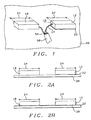
- FIG. 1 shows a perspective drawing of a dipole antenna with a radiating antenna element 12 and a counterpoise antenna element 10 formed from conductive loaded resin-based materials.
- the antenna comprises a radiating antenna element 12 and a counterpoise antenna element 10 each having a length 24 and a rectangular cross section perpendicular to the length 24. The length 24 is greater than three multiplied by the square root of the cross sectional area.
- the center conductor 14 of a coaxial cable 50 is electrically connected to the radiating antenna element 12 using a metal insert 15 formed in the radiating antenna element 12.
- the shield 52 of the coaxial cable 50 is connected to the counterpoise antenna element 10 using a metal insert formed in the counterpoise antenna element 10.
- the metal insert in the counterpoise antenna element 10 is not visible in Fig. 1 but is the same as the metal insert 15 in the radiating antenna element 12.
- the length 24 is a multiple of a quarter wavelength of the optimum frequency of detection or transmission of the antenna.
- the impedance of the antenna at resonance should be very nearly equal to the impedance of the coaxial cable 50 to assure maximum power transfer between cable and antenna.
- Fig. 3 shows a detailed view of a metal insert 15 formed in a segment 11 of an antenna element.
- the metal insert can be copper or other metal.
- a screw 17 can be used in the metal insert 15 to aid in electrical connections. Soldering or other electrical connection methods can also be used.
- Fig. 1 shows an example of a dipole antenna with the radiating antenna element 12 placed on a layer of insulating material 22, which is placed on a ground plane 20, and the counterpoise antenna element 10 placed directly on the ground plane 20.
- the ground plane 20 is optional and if the ground plane is not used the layer of insulating material 22 may not be necessary.
- the counterpoise antenna element 10 can also be placed on a layer of insulating material 22, see Fig. 2A. If the ground plane 20 is used it can also be formed of the conductive loaded resin-based materials.
- Fig. 2A shows a front view of the dipole antenna of Fig. 1 for the example of an antenna using a ground plane 20, a layer of insulating material 22 between the radiating antenna element 12 and the ground plane 20, and the counterpoise antenna element 10 placed directly on the ground plane 20.
- Fig. 2B shows a front view of the dipole antenna of Fig. 1 for the example of an antenna using a ground plane 20 and a layer of insulating material 22 between both the radiating antenna element 12 and the counterpoise antenna element 10.
- an amplifier 72 can be inserted between the center conductor 14 of the coaxial cable and the radiating antenna element 12.
- a wire 70 connects metal insert 15 in the radiating antenna element 12 to the amplifier 72.
- the input of the amplifier 72 is connected to the radiating antenna element 12 and the output of the amplifier 72 is connected to the center conductor 14 of the coaxial cable 50.
- the output of the amplifier 72 is connected to the radiating antenna element 12 and the input of the amplifier 72 is connected to the center conductor 14 of the coaxial cable 50.
- the length 24 is about 1.5 inches with a square cross section of about 0.09 square inches.
- This antenna had a center frequency of about 900 MHz.
- Figs. 4A and 4B show perspective views of a patch antenna with a radiating antenna element 40 and a ground plane 42 formed from conductive loaded resin-based materials.
- the antenna comprises a radiating antenna element 40 and a ground plane 42 each having the shape of a rectangular plate with a thickness 44 and a separation between the plates 46 provided by insulating standoffs 60.
- the square root of the area of the rectangular square plate forming the radiating antenna element 40 is greater than three multiplied by the thickness 44.
- the patch antenna provided good performance at Global Position System, GPS, frequencies of about 1.5 GHz.
- Fig. 4A shows an example of the patch antenna where the coaxial cable 50 enters through the ground plane 42.
- the coaxial cable shield 52 is connected to the ground plane 42 by means of a metal insert 15 in the ground plane.
- the coaxial cable center conductor 14 is connected to the radiating antenna element 40 by means of a metal insert 15 in the radiating antenna element 40.
- Fig. 4B shows an example of the patch antenna where the coaxial cable 50 enters between the radiating antenna element 40 and the ground plane 42.
- the coaxial cable shield 52 is connected to the ground plane 42 by means of a metal insert 15 in the ground plane 42.
- the coaxial cable center conductor 14 is connected to the radiating antenna element 40 by means of a metal insert 15 in the radiating antenna element 40.
- an amplifier 72 can be inserted between the coaxial cable center conductor 14 and the radiating antenna element 40.
- a wire 70 connects the amplifier 72 to the metal insert 15 in the radiating antenna element 40.
- the input of the amplifier 72 is connected to the radiating antenna element 40 and the output of the amplifier 72 is connected to the center conductor 14 of the coaxial cable 50.
- the output of the amplifier 72 is connected to the radiating antenna element 40 and the input of the amplifier 72 is connected to the center conductor 14 of the coaxial cable 50.
- Fig. 6 shows an example of a monopole antenna having a radiating antenna element 64, having a height 71, arranged perpendicular to a ground plane 68.
- the radiating antenna element 64 and the ground plane 68 are formed of conductive plastic or conductive composite materials.
- a layer of insulating material 66 separates the radiating antenna element 64 from the ground plane 68.
- the height 71 of the radiating antenna element 64 is greater than three times the square root of the cross sectional area of the radiating antenna element 64.
- An example of this antenna with a height 71 of 1.17 inches performed well at GPS frequencies of about 1.5 GHz.
- Fig. 7 shows an example of the monopole antenna described above with an amplifier 72 inserted between the center conductor 14 of the coaxial cable 50 and the radiating antenna element 64.
- the input of the amplifier 72 is connected to the radiating antenna element 64 and the output of the amplifier 72 is connected to the center conductor 14 of the coaxial cable 50.
- the output of the amplifier 72 is connected to the radiating antenna element 64 and the input of the amplifier 72 is connected to the center conductor 14 of the coaxial cable 50.
- Figs. 8A, 8B, and 8C shows an example of an L shaped antenna having a radiating antenna element 80 over a ground plane 98.
- the radiating antenna element 80 and the ground plane 98 are formed of conductive loaded resin-based materials.
- a layer of insulating material 96 separates the radiating antenna element 64 from the ground plane 98.
- the radiating antenna element 80 is made up of a first leg 82 and a second leg 84.
- Fig. 8A shows a top view of the antenna.
- Fig. 8B shows a cross section of the first leg 82.
- Fig. 8C shows a cross section of the second leg 84.
- Figs. 8B and 8C show the ground plane 98 and the layer of insulating material 96.
- the cross sectional area of the first leg 82 and the second leg 84 need not be the same.
- Antennas of this type may be typically built using overmolding technique to join the conductive resin-based material to the
- Figs. 9A and 9B show a dipole antenna, formed of conductive loaded resin-based materials, embedded in an automobile bumper 100, formed of insulating material.
- the dipole antenna has a radiating antenna element 102 and a counterpoise antenna element 104.
- Fig. 9A shows the top view of the bumper 100 with the embedded antenna.
- Fig. 9B shows the front view of the bumper 100 with the embedded antenna.
- the antennas of this invention can be used for a number of additional applications.
- Antennas of this type can be embedded in the molding of a window of a vehicle, such as an automobile or an airplane.
- Fig. 10A shows a schematic view of such a window 106.
- the antenna 110 can be embedded in the molding 108.
- Antennas of this type can be embedded in the plastic housing, or be part of the plastic shell itself, of portable electronic devices such as cellular phones, personal computers, or the like.
- Fig. 10B shows a schematic view of a segment 112 of such a plastic housing with the antenna 110 embedded in the housing 112.
Abstract
Description
- This invention relates to antennas formed of conductive loaded resin-based materials comprising micron conductive powders or micron conductive fibers.
- Antennas are an essential part of electronic communication systems that contain wireless links. Low cost antennas offer significant advantages for these systems.
- U.S. Pat. No. 5,771,027 to Marks et al. describes a composite antenna having a grid comprised of electrical conductors woven into the warp of a resin reinforced cloth forming one layer of a multi-layer laminate structure of an antenna.
- U.S. Pat. No. 6,249,261 B1 to Solberg, Jr. et al. describes a direction-finding material constructed from polymer composite materials which are electrically conductive.
- Antennas are essential in any electronic systems containing wireless links. Such applications as communications and navigation require reliable sensitive antennas. Antennas are typically fabricated from metal antenna elements in a wide variety of configurations. Lowering the cost of antenna materials or production costs in fabrication of antennas offers significant advantages for any applications utilizing antennas.
- It is a principle objective of this invention to provide antennas fabricated from conductive loaded resin-based materials.
- It is another principle objective of this invention to provide antennas having two antenna elements fabricated from conductive loaded resin-based materials.
- It is another principle objective of this invention to provide antennas having an antenna element and a ground plane fabricated from conductive loaded resin-based materials.
- It is another principle objective of this invention to provide a method of forming antennas from conductive loaded resin-based materials.
- These objectives are achieved by fabricating the antenna elements and ground planes from conductive loaded resin-based materials. These materials are resins loaded with conductive materials to provide a resin-based material which is a conductor rather than an insulator. The resins provide the structural material which, when loaded with micron conductive powders or micron conductive fibers, become composites which are conductors rather than insulators.
- Antenna elements are fabricated from the conductive loaded resins. Almost any type of antenna can be fabricated from the conductive loaded resin-based materials, such as dipole antennas, monopole antennas, planar antennas or the like. These antennas can be tuned to a desired frequency range.
- The antennas can be molded or extruded to provide the desired shape. The conductive loaded resin-based materials can be cut, injection molded, overmolded, laminated, extruded, milled or the like to provide the desired antenna shape and size. The antenna characteristics depend on the composition of the conductive loaded resin-based materials, which can be adjusted to aid in achieving the desired antenna characteristics. Virtually any antenna fabricated by conventional means such as wire, strip-line, printed circuit boards, or the like can be fabricated using the conductive loaded resin-based materials.
-
- Fig. 1 shows a perspective view of a dipole antenna formed from a conductive loaded resin-based material.
- Fig. 2A shows a front view of the dipole antenna of Fig.1 showing insulating material between the radiating antenna element and a ground plane.
- Fig. 2B shows a front view of the dipole antenna of Fig.1 showing insulating material between both the radiating antenna element and the counterpoise antenna element and a ground plane.
- Fig. 2C shows an amplifier inserted between the radiating antenna element and the coaxial cable center conductor for the dipole antenna of Fig. 1.
- Fig. 3 shows a segment of an antenna element formed from a conductive loaded resin-based material showing a metal insert for connecting to conducting cable elements.
- Fig. 4A shows a perspective view of a patch antenna comprising a radiating antenna element and a ground plane with the coaxial cable entering through the ground plane.
- Fig. 4B shows a perspective view of a patch antenna comprising a radiating antenna element and a ground plane with the coaxial cable entering between the ground plane and the radiating antenna element.
- Fig. 5 shows an amplifier inserted between the radiating antenna element and the coaxial cable center conductor for the patch antenna of Figs. 4A and 4B.
- Fig. 6 shows a perspective view of a monopole antenna formed from a conductive loaded resin-based material.
- Fig. 7 shows a perspective view of a monopole antenna formed from a conductive loaded resin-based material with an amplifier between the radiating antenna element and the coaxial cable center conductor.
- Fig. 8A shows a top view of an antenna having a single L shaped antenna element formed from a conductive loaded resin-based material.
- Fig. 8B shows a cross section view of the antenna
element of Fig. 8A taken along
line 8B-8B' of Fig. 8A. - Fig. 8C shows a cross section view of the antenna
element of Fig. 8A taken along
line 8C-8C' of Fig. 8A. - Fig. 9A shows a top view of an antenna formed from a conductive loaded resin-based material embedded in an automobile bumper.
- Fig. 9B shows a front view of an antenna formed from a conductive loaded resin-based material embedded in an automobile bumper formed of an insulator such as rubber.
- Fig. 10A shows a schematic view of an antenna formed from a conductive loaded resin-based material embedded in the molding of a vehicle window.
- Fig. 10B shows a schematic view of an antenna formed from a conductive loaded resin-based material embedded in the plastic case of a portable electronic device.
-
- The following embodiments are examples of antennas fabricated using conductive loaded resin-based materials. In some of the examples ground planes are also used and these ground planes can be formed of either conductive loaded resin-based materials or metals. The use of these conductive loaded resin-based materials in antenna fabrication significantly lowers the cost of materials and manufacturing processes used in the assembly antennas and the ease of forming these materials into the desired shapes. These materials can be used to form either receiving or transmitting antennas. The antennas and/or ground planes can be formed using methods such as injection molding, overmolding, or extrusion of the conductive loaded resin-based materials.
- The conductive loaded resin-based materials typically but not exclusively have a conductivity of between about 5 and 25 ohms per square. The antenna elements, used to form the antennas, are formed of the conductive loaded resin-based materials and can be formed using methods such as injection molding, overmolding, or extrusion. The antenna elements can also be stamped to produce the desired shape. The conductive loaded resin-based material antenna elements can also be cut or milled as desired.
- The conductive loaded resin-based materials comprise micron conductive powders or fibers loaded in a structural resin. The micron conductive powders are formed of metals such as nickel, copper, silver or the like. The micron conductive fibers can be nickel plated carbon fiber, stainless steel fiber, copper fiber, silver fiber, or the like. The structural material is a material such as a polymer resin. Structural material can be, here given as examples and not as an exhaustive list, polymer resins produced by GE PLASTICS, Pittsfield, MA, a range of other plastics produced by GE PLASTICS, Pittsfield, MA, a range of other plastics produced by other manufacturers, silicones produced by GE SILICONES, Waterford, NY, or other flexible resin-based rubber compounds produced by other manufacturers. The resin-based structural material loaded with micron conductive powders or fibers can be molded, using a method such as injection molding, overmolding, or extruded to the desired shape. The conductive loaded resin-based materials can be cut or milled as desired to form the desired shape of the antenna elements. The composition of the composite materials can affect the antenna characteristics and must be properly controlled. The composite could also be in the family of polyesters with woven or webbed micron stainless steel fibers or other micron conductive fibers forming a cloth like material which, when properly designed in metal content and shape, can be used to realize a very high performance cloth antenna. Such a cloth antenna could be embedded in a persons clothing as well as in insulating materials such as rubber or plastic. The woven or webbed conductive cloths could also be laminated to materials such as Teflon, FR-4, or any resin-based hard material.
- Refer now to Figs. 1-10B for examples of antennas fabricated using conductive loaded resin-based materials. These antennas can be either receiving or transmitting antennas. Fig. 1 shows a perspective drawing of a dipole antenna with a radiating
antenna element 12 and acounterpoise antenna element 10 formed from conductive loaded resin-based materials. The antenna comprises a radiatingantenna element 12 and acounterpoise antenna element 10 each having alength 24 and a rectangular cross section perpendicular to thelength 24. Thelength 24 is greater than three multiplied by the square root of the cross sectional area. Thecenter conductor 14 of acoaxial cable 50 is electrically connected to the radiatingantenna element 12 using ametal insert 15 formed in the radiatingantenna element 12. Theshield 52 of thecoaxial cable 50 is connected to thecounterpoise antenna element 10 using a metal insert formed in thecounterpoise antenna element 10. The metal insert in thecounterpoise antenna element 10 is not visible in Fig. 1 but is the same as themetal insert 15 in the radiatingantenna element 12. Thelength 24 is a multiple of a quarter wavelength of the optimum frequency of detection or transmission of the antenna. The impedance of the antenna at resonance should be very nearly equal to the impedance of thecoaxial cable 50 to assure maximum power transfer between cable and antenna. - Fig. 3 shows a detailed view of a
metal insert 15 formed in asegment 11 of an antenna element. The metal insert can be copper or other metal. Ascrew 17 can be used in themetal insert 15 to aid in electrical connections. Soldering or other electrical connection methods can also be used. - Fig. 1 shows an example of a dipole antenna with the radiating
antenna element 12 placed on a layer of insulatingmaterial 22, which is placed on aground plane 20, and thecounterpoise antenna element 10 placed directly on theground plane 20. Theground plane 20 is optional and if the ground plane is not used the layer of insulatingmaterial 22 may not be necessary. As another option thecounterpoise antenna element 10 can also be placed on a layer of insulatingmaterial 22, see Fig. 2A. If theground plane 20 is used it can also be formed of the conductive loaded resin-based materials. - Fig. 2A shows a front view of the dipole antenna of Fig. 1 for the example of an antenna using a
ground plane 20, a layer of insulatingmaterial 22 between the radiatingantenna element 12 and theground plane 20, and thecounterpoise antenna element 10 placed directly on theground plane 20. Fig. 2B shows a front view of the dipole antenna of Fig. 1 for the example of an antenna using aground plane 20 and a layer of insulatingmaterial 22 between both the radiatingantenna element 12 and thecounterpoise antenna element 10. - As shown in Fig. 2C, an
amplifier 72 can be inserted between thecenter conductor 14 of the coaxial cable and the radiatingantenna element 12. Awire 70 connectsmetal insert 15 in the radiatingantenna element 12 to theamplifier 72. For receiving antennas the input of theamplifier 72 is connected to the radiatingantenna element 12 and the output of theamplifier 72 is connected to thecenter conductor 14 of thecoaxial cable 50. For transmitting antennas the output of theamplifier 72 is connected to the radiatingantenna element 12 and the input of theamplifier 72 is connected to thecenter conductor 14 of thecoaxial cable 50. - In one example of this antenna the
length 24 is about 1.5 inches with a square cross section of about 0.09 square inches. This antenna had a center frequency of about 900 MHz. - Figs. 4A and 4B show perspective views of a patch antenna with a radiating
antenna element 40 and aground plane 42 formed from conductive loaded resin-based materials. The antenna comprises a radiatingantenna element 40 and aground plane 42 each having the shape of a rectangular plate with athickness 44 and a separation between theplates 46 provided by insulatingstandoffs 60. The square root of the area of the rectangular square plate forming the radiatingantenna element 40 is greater than three multiplied by thethickness 44. In one example of this antenna wherein the rectangular plate is a square with sides of 1.4 inches and a thickness of 0.41 inches the patch antenna provided good performance at Global Position System, GPS, frequencies of about 1.5 GHz. - Fig. 4A shows an example of the patch antenna where the
coaxial cable 50 enters through theground plane 42. Thecoaxial cable shield 52 is connected to theground plane 42 by means of ametal insert 15 in the ground plane. The coaxialcable center conductor 14 is connected to the radiatingantenna element 40 by means of ametal insert 15 in the radiatingantenna element 40. Fig. 4B shows an example of the patch antenna where thecoaxial cable 50 enters between the radiatingantenna element 40 and theground plane 42. Thecoaxial cable shield 52 is connected to theground plane 42 by means of ametal insert 15 in theground plane 42. The coaxialcable center conductor 14 is connected to the radiatingantenna element 40 by means of ametal insert 15 in the radiatingantenna element 40. - As shown in Fig. 5 an
amplifier 72 can be inserted between the coaxialcable center conductor 14 and the radiatingantenna element 40. Awire 70 connects theamplifier 72 to themetal insert 15 in the radiatingantenna element 40. For receiving antennas the input of theamplifier 72 is connected to the radiatingantenna element 40 and the output of theamplifier 72 is connected to thecenter conductor 14 of thecoaxial cable 50. For transmitting antennas the output of theamplifier 72 is connected to the radiatingantenna element 40 and the input of theamplifier 72 is connected to thecenter conductor 14 of thecoaxial cable 50. - Fig. 6 shows an example of a monopole antenna having a radiating
antenna element 64, having aheight 71, arranged perpendicular to aground plane 68. The radiatingantenna element 64 and theground plane 68 are formed of conductive plastic or conductive composite materials. A layer of insulatingmaterial 66 separates the radiatingantenna element 64 from theground plane 68. Theheight 71 of the radiatingantenna element 64 is greater than three times the square root of the cross sectional area of the radiatingantenna element 64. An example of this antenna with aheight 71 of 1.17 inches performed well at GPS frequencies of about 1.5 GHz. - Fig. 7 shows an example of the monopole antenna described above with an
amplifier 72 inserted between thecenter conductor 14 of thecoaxial cable 50 and the radiatingantenna element 64. For receiving antennas the input of theamplifier 72 is connected to the radiatingantenna element 64 and the output of theamplifier 72 is connected to thecenter conductor 14 of thecoaxial cable 50. For transmitting antennas the output of theamplifier 72 is connected to the radiatingantenna element 64 and the input of theamplifier 72 is connected to thecenter conductor 14 of thecoaxial cable 50. - Figs. 8A, 8B, and 8C shows an example of an L shaped antenna having a radiating
antenna element 80 over aground plane 98. The radiatingantenna element 80 and theground plane 98 are formed of conductive loaded resin-based materials. A layer of insulatingmaterial 96 separates the radiatingantenna element 64 from theground plane 98. The radiatingantenna element 80 is made up of afirst leg 82 and asecond leg 84. Fig. 8A shows a top view of the antenna. Fig. 8B shows a cross section of thefirst leg 82. Fig. 8C shows a cross section of thesecond leg 84. Figs. 8B and 8C show theground plane 98 and the layer of insulatingmaterial 96. The cross sectional area of thefirst leg 82 and thesecond leg 84 need not be the same. Antennas of this type may be typically built using overmolding technique to join the conductive resin-based material to the insulating material. - Antennas of this type have a number of uses. Figs. 9A and 9B show a dipole antenna, formed of conductive loaded resin-based materials, embedded in an
automobile bumper 100, formed of insulating material. The dipole antenna has a radiatingantenna element 102 and acounterpoise antenna element 104. Fig. 9A shows the top view of thebumper 100 with the embedded antenna. Fig. 9B shows the front view of thebumper 100 with the embedded antenna. - The antennas of this invention, formed of, can be used for a number of additional applications. Antennas of this type can be embedded in the molding of a window of a vehicle, such as an automobile or an airplane. Fig. 10A shows a schematic view of such a
window 106. Theantenna 110 can be embedded in themolding 108. Antennas of this type can be embedded in the plastic housing, or be part of the plastic shell itself, of portable electronic devices such as cellular phones, personal computers, or the like. Fig. 10B shows a schematic view of asegment 112 of such a plastic housing with theantenna 110 embedded in thehousing 112. - While the invention has been particularly shown and described with reference to the preferred embodiments thereof, it will be understood by those skilled in the art that various changes in form and details may be made without departing from the spirit and scope of the invention.
Claims (17)
- An antenna, comprising:a number of antenna elements wherein said antenna elements are formed of conductive loaded resin-based materials; andelectrical communication to said antenna elements.
- The antenna of claim 1 wherein said antenna elements are imbedded in a plastic case for portable electronic equipment or in vehicle window moldings.
- An antenna, comprising:a first antenna element formed of conductive loaded resin-based materials;a second antenna element formed of conductive loaded resin-based materials; andelectrical connections to said first antenna element and said second antenna element.
- The antenna of claim 3 wherein said first antenna element and said second antenna element each have a length and a rectangular cross sectional area and are arranged in a dipole configuration.
- The antenna of claim 3 wherein said first antenna element and said second antenna element are imbedded either in a plastic case for portable electronic equipment, or in an automobile bumper formed of insulating material, or in vehicle window moldings.
- An antenna, comprising:an antenna element formed of conductive loaded resin-based materials;a conducting ground plane;insulating material separating said antenna element from said ground plane; andelectrical connections to said antenna element and said ground plane.
- The antenna of claim 6 wherein said ground plane is formed of conductive loaded resin-based materials.
- The antenna of claim 6 wherein said conductive loaded resin-based materials comprises micron conductive powders or micron conductive fibers or petrochemicals or silicones or polyesters with woven or webbed micron conductive fibers forming a cloth like material.
- The antenna of claim 1 or 3 or 6 wherein said antenna can be a radiating antenna, a receiving antenna, or both.
- The antenna of claim 6 wherein said antenna element is perpendicular to said ground plane in a monopole configuration.
- The antenna of claim 6 wherein said antenna element is a rectangular plate parallel to said ground plane.
- The antenna of claim 6 wherein said antenna element and said ground plane are imbedded in a plastic case for portable electronic equipment or in an automobile bumper formed of insulating material or in vehicle window moldings.
- The antenna of claim 3 or 6 wherein said electrical connections comprise a coaxial cable having a center conductor and further comprising an amplifier connected between said antenna element and said center conductor of said coaxial cable.
- A method of forming an antenna, comprising:forming a number of antenna elements from conductive loaded resin-based materials using injection molding or extrusion;arranging said antenna elements in an antenna array; andforming electrical connections to said antenna elements.
- The method of claim 14 wherein said antenna array forms a dipole antenna or a monopole antenna.
- The method of claim 14 wherein said antenna elements are rectangular plates and said antenna array forms a patch antenna.
- The method of claim 14 wherein said conductive loaded resin-based materials comprises micron conductive powders or micron conductive fibers, or petrochemicals, or silicones.
Applications Claiming Priority (6)
| Application Number | Priority Date | Filing Date | Title |
|---|---|---|---|
| US26882201P | 2001-02-15 | 2001-02-15 | |
| US268822P | 2001-02-15 | ||
| US26941401P | 2001-02-16 | 2001-02-16 | |
| US269414P | 2001-02-16 | ||
| US31780801P | 2001-09-07 | 2001-09-07 | |
| US317808P | 2001-09-07 |
Publications (2)
| Publication Number | Publication Date |
|---|---|
| EP1233426A2 true EP1233426A2 (en) | 2002-08-21 |
| EP1233426A3 EP1233426A3 (en) | 2003-07-09 |
Family
ID=27402113
Family Applications (1)
| Application Number | Title | Priority Date | Filing Date |
|---|---|---|---|
| EP02368015A Withdrawn EP1233426A3 (en) | 2001-02-15 | 2002-02-15 | Antennas with conductive plastics or conductive composites |
Country Status (3)
| Country | Link |
|---|---|
| US (2) | US6741221B2 (en) |
| EP (1) | EP1233426A3 (en) |
| CA (1) | CA2371986C (en) |
Cited By (9)
| Publication number | Priority date | Publication date | Assignee | Title |
|---|---|---|---|---|
| EP1427055A1 (en) * | 2002-12-04 | 2004-06-09 | Integral Technologies, Inc. | Low cost antennas using conductive plastics or conductive composites |
| EP1447819A1 (en) * | 2003-02-14 | 2004-08-18 | Integral Technologies, Inc. | Low cost antennas and electromagnetic (EMF) absorption in electronic circuit packages or transceivers using conductive loaded resin-based materials |
| EP1463146A1 (en) * | 2003-03-24 | 2004-09-29 | Integral Technologies, Inc. | Low cost antennas from conductive loaded resin-based materials having a conductive wire center core and production method |
| WO2005062418A1 (en) | 2003-12-19 | 2005-07-07 | Sony Corporation | Antenna device, radio device, and electronic instrument |
| US6947005B2 (en) | 2001-02-15 | 2005-09-20 | Integral Technologies, Inc. | Low cost antennas and electromagnetic (EMF) absorption in electronic circuit packages or transceivers using conductive loaded resin-based materials |
| US7006050B2 (en) | 2001-02-15 | 2006-02-28 | Integral Technologies, Inc. | Low cost antennas manufactured from conductive loaded resin-based materials having a conducting wire center core |
| EP1696504A1 (en) * | 2003-12-19 | 2006-08-30 | Sony Corporation | Antenna device, radio device, and electronic instrument |
| US20090085427A1 (en) * | 2007-10-01 | 2009-04-02 | The Regents Of The University Of Michigan | Electrical power generation from fluid flow |
| US8268222B2 (en) | 2001-02-15 | 2012-09-18 | Integral Technologies, Inc. | Methods of making electrical motor components from conductive loaded resin-based materials |
Families Citing this family (67)
| Publication number | Priority date | Publication date | Assignee | Title |
|---|---|---|---|---|
| US20060128895A1 (en) * | 2001-02-15 | 2006-06-15 | Thomas Aisenbrey | Electriplast thermoset wet mix material and method of manufacture |
| US20050200329A1 (en) * | 2001-02-15 | 2005-09-15 | Integral Technologies, Inc. | Low cost charger connections manufactured from conductive loaded resin-based material |
| US20050167189A1 (en) * | 2001-02-15 | 2005-08-04 | Integral Technologies, Inc. | Low cost acoustical structures manufactured from conductive loaded resin-based materials |
| US7372127B2 (en) * | 2001-02-15 | 2008-05-13 | Integral Technologies, Inc. | Low cost and versatile resistors manufactured from conductive loaded resin-based materials |
| US7317420B2 (en) * | 2001-02-15 | 2008-01-08 | Integral Technologies, Inc. | Low cost omni-directional antenna manufactured from conductive loaded resin-based materials |
| US6940468B2 (en) * | 2001-02-15 | 2005-09-06 | Integral Technologies, Inc. | Transformers or inductors (“transductors”) and antennas manufactured from conductive loaded resin-based materials |
| US7079086B2 (en) * | 2001-02-15 | 2006-07-18 | Integral Technologies, Inc. | Low cost electromagnetic field absorbing devices manufactured from conductive loaded resin-based materials |
| US7222727B2 (en) * | 2001-02-15 | 2007-05-29 | Integral Technologies, Inc. | Low cost food processing belts and other conveyances manufactured from conductive loaded resin-based materials |
| US7027304B2 (en) | 2001-02-15 | 2006-04-11 | Integral Technologies, Inc. | Low cost thermal management device or heat sink manufactured from conductive loaded resin-based materials |
| US7316838B2 (en) * | 2001-02-15 | 2008-01-08 | Integral Technologies, Inc. | Low cost electrically conductive carpeting manufactured from conductive loaded resin-based materials |
| US20040227688A1 (en) * | 2001-02-15 | 2004-11-18 | Integral Technologies, Inc. | Metal plating of conductive loaded resin-based materials for low cost manufacturing of conductive articles |
| US20050191788A1 (en) * | 2001-02-15 | 2005-09-01 | Integral Technologies, Inc. | Low cost magnetic brakes and motion control devices manufactured from conductive loaded resin-based materials |
| US20110024275A1 (en) * | 2001-02-16 | 2011-02-03 | Integral Technologies, Inc. | Low cost key actuators and other switching device actuators manufactured from conductive loaded resin-based materials |
| SE522031C2 (en) * | 2001-07-12 | 2004-01-07 | Perlos Ab | Two-component antenna and method of making such |
| US6873298B1 (en) * | 2002-09-25 | 2005-03-29 | Integral Technologies, Inc. | Plastenna flat panel antenna |
| WO2004070871A1 (en) * | 2003-02-10 | 2004-08-19 | Sony Ericsson Mobile Communications Ab | Combined speaker and antenna component |
| US6953619B2 (en) * | 2003-02-12 | 2005-10-11 | E. I. Du Pont De Nemours And Company | Conductive thermoplastic compositions and antennas thereof |
| CA2464153A1 (en) * | 2003-04-14 | 2004-10-14 | Integral Technologies, Inc. | Low cost lighting circuits manufactured from conductive loaded resin-based materials |
| US7973733B2 (en) * | 2003-04-25 | 2011-07-05 | Qualcomm Incorporated | Electromagnetically coupled end-fed elliptical dipole for ultra-wide band systems |
| US20050033397A1 (en) * | 2003-08-04 | 2005-02-10 | Integral Technologies, Inc. | Low cost electrical stimulation and shock devices manufactured from conductive loaded resin-based materials |
| US20050112331A1 (en) * | 2003-11-25 | 2005-05-26 | Constantin Donea | Multiwall sheets and methods for manufacturing thereof |
| EP1695100A4 (en) * | 2003-12-18 | 2009-12-30 | Lecroy Corp | Resistive probe tips |
| US7321234B2 (en) * | 2003-12-18 | 2008-01-22 | Lecroy Corporation | Resistive test probe tips and applications therefor |
| US7397429B2 (en) * | 2004-03-09 | 2008-07-08 | Northrop Grumman Corporation | Aircraft window plug antenna assembly |
| US7461444B2 (en) * | 2004-03-29 | 2008-12-09 | Deaett Michael A | Method for constructing antennas from textile fabrics and components |
| WO2005119837A2 (en) * | 2004-06-01 | 2005-12-15 | Integral Technologies, Inc. | Low cost food processing, preparation, and handling devices manufactured from conductive loaded resin- based materials |
| US7193581B2 (en) * | 2004-06-01 | 2007-03-20 | Miltope Corporation | Electronic equipment shock isolation/protection bumper, with integrated antenna |
| US7352338B2 (en) * | 2004-07-21 | 2008-04-01 | Motorola, Inc. | Wideband antenna with reduced dielectric loss |
| WO2006047007A2 (en) * | 2004-09-02 | 2006-05-04 | E.I. Dupont De Nemours And Company | Radio frequency coupling structure for coupling to an electronic device |
| WO2006047006A2 (en) * | 2004-09-02 | 2006-05-04 | E.I. Dupont De Nemours And Company | Method for making a radio frequency coupling structure |
| US7760141B2 (en) * | 2004-09-02 | 2010-07-20 | E.I. Du Pont De Nemours And Company | Method for coupling a radio frequency electronic device to a passive element |
| US8178958B2 (en) | 2004-10-19 | 2012-05-15 | Semiconductor Energy Laboratory Co., Ltd. | Semiconductor device having antenna and method for manufacturing thereof |
| US7158089B2 (en) * | 2004-11-29 | 2007-01-02 | Qualcomm Incorporated | Compact antennas for ultra wide band applications |
| US20060202894A1 (en) * | 2005-03-09 | 2006-09-14 | Shary Nassimi | Conductive Plastic Antenna |
| US20060270301A1 (en) * | 2005-05-25 | 2006-11-30 | Northrop Grumman Corporation | Reflective surface for deployable reflector |
| US7862049B2 (en) * | 2006-04-17 | 2011-01-04 | Federal Mogul World Wide, Inc. | Gasket and method of forming a seal therewith |
| DE102008004320A1 (en) * | 2007-02-02 | 2008-08-14 | Hirschmann Car Communication Gmbh | Antenna, in particular for data communication via satellite |
| US7612723B2 (en) * | 2007-02-02 | 2009-11-03 | Sony Ericsson Mobile Communications Ab | Portable communication device antenna arrangement |
| KR101456673B1 (en) * | 2007-09-11 | 2014-11-03 | 삼성전자주식회사 | Tape structure, and method and apparatus for separating a wafer using the same |
| JP2012500142A (en) | 2008-08-18 | 2012-01-05 | プロダクティブ リサーチ エルエルシー. | Formable lightweight composite |
| US8680758B2 (en) * | 2008-10-20 | 2014-03-25 | Federal-Mogul Ignition Company | Spark plug having a plastic upper insulator and method of construction |
| FR2947321A1 (en) * | 2009-06-26 | 2010-12-31 | Schrader Sas | VALVE INTEGRATING A SENSOR |
| US11342791B2 (en) | 2009-12-22 | 2022-05-24 | View, Inc. | Wirelessly powered and powering electrochromic windows |
| US11630366B2 (en) | 2009-12-22 | 2023-04-18 | View, Inc. | Window antennas for emitting radio frequency signals |
| US11732527B2 (en) | 2009-12-22 | 2023-08-22 | View, Inc. | Wirelessly powered and powering electrochromic windows |
| US20130271813A1 (en) | 2012-04-17 | 2013-10-17 | View, Inc. | Controller for optically-switchable windows |
| US11205926B2 (en) | 2009-12-22 | 2021-12-21 | View, Inc. | Window antennas for emitting radio frequency signals |
| WO2011082128A1 (en) | 2009-12-28 | 2011-07-07 | Productive Researsh Llc. | Processes for welding composite materials and articles therefrom |
| US9415568B2 (en) | 2010-02-15 | 2016-08-16 | Productive Research Llc | Formable light weight composite material systems and methods |
| US8617364B2 (en) | 2011-08-29 | 2013-12-31 | Mine Safety Appliances Company | Sensors and sensor housing systems |
| JP5254423B2 (en) * | 2011-11-04 | 2013-08-07 | 株式会社東芝 | Coupler device and communication device |
| US11300848B2 (en) | 2015-10-06 | 2022-04-12 | View, Inc. | Controllers for optically-switchable devices |
| US9233526B2 (en) | 2012-08-03 | 2016-01-12 | Productive Research Llc | Composites having improved interlayer adhesion and methods thereof |
| CA3156883A1 (en) | 2014-03-05 | 2015-09-11 | View, Inc. | Monitoring sites containing switchable optical devices and controllers |
| CN111106426B (en) | 2014-11-25 | 2021-12-03 | 唯景公司 | Window antenna |
| US11114742B2 (en) | 2014-11-25 | 2021-09-07 | View, Inc. | Window antennas |
| AU2017260101B2 (en) * | 2016-05-06 | 2021-07-22 | View, Inc. | Window antennas |
| CN106207448A (en) * | 2016-08-26 | 2016-12-07 | 长安大学 | A kind of utilize three-D photon crystal as the dipole antenna of reflection substrate |
| US10476142B2 (en) | 2016-12-21 | 2019-11-12 | Cts Corporation | Radio frequency antenna with granular or powder insulating material and method of making the same |
| CN106939897A (en) * | 2017-04-11 | 2017-07-11 | 天门市江汉石油三机传动设备有限公司 | A kind of pump labyrinth type combination sealing and its preparation |
| JP7124570B2 (en) * | 2018-09-03 | 2022-08-24 | トヨタ自動車株式会社 | rotor |
| US11338552B2 (en) | 2019-02-15 | 2022-05-24 | Productive Research Llc | Composite materials, vehicle applications and methods thereof |
| CN110739526B (en) * | 2019-10-29 | 2021-07-13 | 中国科学院微电子研究所 | Antenna radio frequency front end package manufacturing method |
| TW202206925A (en) | 2020-03-26 | 2022-02-16 | 美商視野公司 | Access and messaging in a multi client network |
| US11631493B2 (en) | 2020-05-27 | 2023-04-18 | View Operating Corporation | Systems and methods for managing building wellness |
| KR102589937B1 (en) * | 2021-04-01 | 2023-10-17 | 현대모비스 주식회사 | Wave guide for radar |
| CN115954682B (en) * | 2023-02-28 | 2023-09-12 | 湖南博翔新材料有限公司 | Light wave-absorbing material and application thereof |
Family Cites Families (17)
| Publication number | Priority date | Publication date | Assignee | Title |
|---|---|---|---|---|
| JPS534238B1 (en) * | 1967-08-23 | 1978-02-15 | ||
| DE1916326A1 (en) * | 1968-04-01 | 1969-10-30 | Barracudaverken Ab | Camouflage means for preventing or inhibiting detection by radar reconnaissance |
| US4288352A (en) * | 1979-03-26 | 1981-09-08 | Exxon Research & Engineering Co. | Electrically conductive polymeric compositions |
| GB2100933B (en) * | 1981-06-25 | 1985-04-17 | Standard Telephones Cables Ltd | Permanently connecting a set of conductive tracks on a substrate with a cooperating set on a printed circuit. |
| DE4227208A1 (en) | 1992-08-17 | 1994-02-24 | Hirschmann Richard Gmbh Co | Antenna combination |
| JP3232730B2 (en) | 1992-12-22 | 2001-11-26 | 株式会社デンソー | Microstrip antenna |
| US5420596A (en) * | 1993-11-26 | 1995-05-30 | Motorola, Inc. | Quarter-wave gap-coupled tunable strip antenna |
| JPH07162220A (en) | 1993-12-08 | 1995-06-23 | Furukawa Electric Co Ltd:The | Antenna module |
| US5421376A (en) * | 1994-01-21 | 1995-06-06 | Lockheed Missiles & Space Co., Inc. | Metallized mesh fabric panel construction for RF reflector |
| US5440801A (en) | 1994-03-03 | 1995-08-15 | Composite Optics, Inc. | Composite antenna |
| EP0910935A1 (en) * | 1996-06-12 | 1999-04-28 | Brunel University | Electrical circuit |
| EP0862240B1 (en) | 1997-02-28 | 1998-10-14 | Top Glass S.p.A. | Method of making whip antennas and whip antenna made thereby |
| US6127474A (en) * | 1997-08-27 | 2000-10-03 | Andelman; Marc D. | Strengthened conductive polymer stabilized electrode composition and method of preparing |
| EP1024552A3 (en) | 1999-01-26 | 2003-05-07 | Siemens Aktiengesellschaft | Antenna for radio communication terminals |
| US6147662A (en) | 1999-09-10 | 2000-11-14 | Moore North America, Inc. | Radio frequency identification tags and labels |
| US6249261B1 (en) | 2000-03-23 | 2001-06-19 | Southwest Research Institute | Polymer, composite, direction-finding antenna |
| US6624383B1 (en) * | 2000-08-30 | 2003-09-23 | Parker-Hannifin Corporation | Using laser etching to improve surface contact resistance of conductive fiber filler polymer composites |
-
2002
- 2002-02-14 US US10/075,778 patent/US6741221B2/en not_active Expired - Fee Related
- 2002-02-15 EP EP02368015A patent/EP1233426A3/en not_active Withdrawn
- 2002-02-15 CA CA002371986A patent/CA2371986C/en not_active Expired - Fee Related
-
2004
- 2004-05-24 US US10/853,448 patent/US20040217903A1/en not_active Abandoned
Non-Patent Citations (1)
| Title |
|---|
| None * |
Cited By (15)
| Publication number | Priority date | Publication date | Assignee | Title |
|---|---|---|---|---|
| US6947005B2 (en) | 2001-02-15 | 2005-09-20 | Integral Technologies, Inc. | Low cost antennas and electromagnetic (EMF) absorption in electronic circuit packages or transceivers using conductive loaded resin-based materials |
| US8268222B2 (en) | 2001-02-15 | 2012-09-18 | Integral Technologies, Inc. | Methods of making electrical motor components from conductive loaded resin-based materials |
| US7006050B2 (en) | 2001-02-15 | 2006-02-28 | Integral Technologies, Inc. | Low cost antennas manufactured from conductive loaded resin-based materials having a conducting wire center core |
| US6870516B2 (en) | 2001-02-16 | 2005-03-22 | Integral Technologies, Inc. | Low cost antennas using conductive plastics or conductive composites |
| EP1427055A1 (en) * | 2002-12-04 | 2004-06-09 | Integral Technologies, Inc. | Low cost antennas using conductive plastics or conductive composites |
| EP1447819A1 (en) * | 2003-02-14 | 2004-08-18 | Integral Technologies, Inc. | Low cost antennas and electromagnetic (EMF) absorption in electronic circuit packages or transceivers using conductive loaded resin-based materials |
| EP1463146A1 (en) * | 2003-03-24 | 2004-09-29 | Integral Technologies, Inc. | Low cost antennas from conductive loaded resin-based materials having a conductive wire center core and production method |
| WO2005062418A1 (en) | 2003-12-19 | 2005-07-07 | Sony Corporation | Antenna device, radio device, and electronic instrument |
| EP1696504A1 (en) * | 2003-12-19 | 2006-08-30 | Sony Corporation | Antenna device, radio device, and electronic instrument |
| EP1696505A1 (en) * | 2003-12-19 | 2006-08-30 | Sony Corporation | Antenna device, radio device, and electronic instrument |
| EP1696504A4 (en) * | 2003-12-19 | 2007-04-11 | Sony Corp | Antenna device, radio device, and electronic instrument |
| EP1696505A4 (en) * | 2003-12-19 | 2007-05-09 | Sony Corp | Antenna device, radio device, and electronic instrument |
| US7327319B2 (en) | 2003-12-19 | 2008-02-05 | Sony Corporation | Antenna device, radio device, and electronic instrument |
| US7511668B2 (en) | 2003-12-19 | 2009-03-31 | Sony Corporation | Antenna device, radio device, and electronic instrument |
| US20090085427A1 (en) * | 2007-10-01 | 2009-04-02 | The Regents Of The University Of Michigan | Electrical power generation from fluid flow |
Also Published As
| Publication number | Publication date |
|---|---|
| US20020109634A1 (en) | 2002-08-15 |
| CA2371986C (en) | 2008-09-30 |
| US20040217903A1 (en) | 2004-11-04 |
| EP1233426A3 (en) | 2003-07-09 |
| US6741221B2 (en) | 2004-05-25 |
| CA2371986A1 (en) | 2002-08-15 |
Similar Documents
| Publication | Publication Date | Title |
|---|---|---|
| US6741221B2 (en) | Low cost antennas using conductive plastics or conductive composites | |
| US6870516B2 (en) | Low cost antennas using conductive plastics or conductive composites | |
| US6768476B2 (en) | Capacitively-loaded bent-wire monopole on an artificial magnetic conductor | |
| US6903687B1 (en) | Feed structure for antennas | |
| CN1127171C (en) | Short-circuit microstrip antenna and device including that antenna | |
| US7006050B2 (en) | Low cost antennas manufactured from conductive loaded resin-based materials having a conducting wire center core | |
| US7317420B2 (en) | Low cost omni-directional antenna manufactured from conductive loaded resin-based materials | |
| US20030020655A1 (en) | Reduced weight artificial dielectric antennas and method for providing the same | |
| US6947005B2 (en) | Low cost antennas and electromagnetic (EMF) absorption in electronic circuit packages or transceivers using conductive loaded resin-based materials | |
| US6940468B2 (en) | Transformers or inductors (“transductors”) and antennas manufactured from conductive loaded resin-based materials | |
| US7009572B1 (en) | Tapered slot antenna | |
| US7230572B2 (en) | Low cost antenna devices comprising conductive loaded resin-based materials with conductive wrapping | |
| CN107121625B (en) | Miniature LS Peano fractal antenna for partial discharge ultrahigh frequency detection | |
| EP3261172B1 (en) | Pcb antenna | |
| EP1447819A1 (en) | Low cost antennas and electromagnetic (EMF) absorption in electronic circuit packages or transceivers using conductive loaded resin-based materials | |
| CA2461969C (en) | Low cost antennas manufactured from conductive loaded resin-based materials having a conductive wire center core | |
| WO2019073334A1 (en) | Antenna apparatus | |
| US6873298B1 (en) | Plastenna flat panel antenna | |
| Dyck et al. | A dielectric-filled cavity-backed lens-coupled dipole antenna at 100 GHz | |
| Fukusako et al. | Design and comparative study on planar small antennas using meander and peano line structure | |
| WO2021121559A1 (en) | A housing for an electronic device | |
| JPH08222944A (en) | Small sized antenna | |
| WO2019098998A1 (en) | Slot antennas | |
| JPH0613814A (en) | Printed antenna | |
| WO2005031912A2 (en) | Low cost omni-directional antenna manufactured from conductive loaded resin-based materials |
Legal Events
| Date | Code | Title | Description |
|---|---|---|---|
| PUAI | Public reference made under article 153(3) epc to a published international application that has entered the european phase |
Free format text: ORIGINAL CODE: 0009012 |
|
| AK | Designated contracting states |
Kind code of ref document: A2 Designated state(s): AT BE CH CY DE DK ES FI FR GB GR IE IT LI LU MC NL PT SE TR |
|
| AX | Request for extension of the european patent |
Free format text: AL;LT;LV;MK;RO;SI |
|
| PUAL | Search report despatched |
Free format text: ORIGINAL CODE: 0009013 |
|
| AK | Designated contracting states |
Designated state(s): AT BE CH CY DE DK ES FI FR GB GR IE IT LI LU MC NL PT SE TR |
|
| AX | Request for extension of the european patent |
Extension state: AL LT LV MK RO SI |
|
| 17P | Request for examination filed |
Effective date: 20040108 |
|
| AKX | Designation fees paid |
Designated state(s): AT BE CH CY DE DK ES FI FR GB GR IE IT LI LU MC NL PT SE TR |
|
| 17Q | First examination report despatched |
Effective date: 20040219 |
|
| 17Q | First examination report despatched |
Effective date: 20040219 |
|
| STAA | Information on the status of an ep patent application or granted ep patent |
Free format text: STATUS: THE APPLICATION IS DEEMED TO BE WITHDRAWN |
|
| 18D | Application deemed to be withdrawn |
Effective date: 20070620 |