EP1234565A2 - Mattress assembly - Google Patents
Mattress assembly Download PDFInfo
- Publication number
- EP1234565A2 EP1234565A2 EP02076709A EP02076709A EP1234565A2 EP 1234565 A2 EP1234565 A2 EP 1234565A2 EP 02076709 A EP02076709 A EP 02076709A EP 02076709 A EP02076709 A EP 02076709A EP 1234565 A2 EP1234565 A2 EP 1234565A2
- Authority
- EP
- European Patent Office
- Prior art keywords
- support
- bladder
- air
- coupled
- width
- Prior art date
- Legal status (The legal status is an assumption and is not a legal conclusion. Google has not performed a legal analysis and makes no representation as to the accuracy of the status listed.)
- Granted
Links
Images


Classifications
-
- A—HUMAN NECESSITIES
- A61—MEDICAL OR VETERINARY SCIENCE; HYGIENE
- A61G—TRANSPORT, PERSONAL CONVEYANCES, OR ACCOMMODATION SPECIALLY ADAPTED FOR PATIENTS OR DISABLED PERSONS; OPERATING TABLES OR CHAIRS; CHAIRS FOR DENTISTRY; FUNERAL DEVICES
- A61G7/00—Beds specially adapted for nursing; Devices for lifting patients or disabled persons
- A61G7/05—Parts, details or accessories of beds
- A61G7/0507—Side-rails
- A61G7/0508—Side-rails characterised by a particular connection mechanism
- A61G7/0509—Side-rails characterised by a particular connection mechanism sliding or pivoting downwards
-
- A—HUMAN NECESSITIES
- A61—MEDICAL OR VETERINARY SCIENCE; HYGIENE
- A61G—TRANSPORT, PERSONAL CONVEYANCES, OR ACCOMMODATION SPECIALLY ADAPTED FOR PATIENTS OR DISABLED PERSONS; OPERATING TABLES OR CHAIRS; CHAIRS FOR DENTISTRY; FUNERAL DEVICES
- A61G7/00—Beds specially adapted for nursing; Devices for lifting patients or disabled persons
- A61G7/05—Parts, details or accessories of beds
- A61G7/0507—Side-rails
- A61G7/052—Side-rails characterised by safety means, e.g. to avoid injuries to patient or caregiver
-
- A—HUMAN NECESSITIES
- A61—MEDICAL OR VETERINARY SCIENCE; HYGIENE
- A61G—TRANSPORT, PERSONAL CONVEYANCES, OR ACCOMMODATION SPECIALLY ADAPTED FOR PATIENTS OR DISABLED PERSONS; OPERATING TABLES OR CHAIRS; CHAIRS FOR DENTISTRY; FUNERAL DEVICES
- A61G7/00—Beds specially adapted for nursing; Devices for lifting patients or disabled persons
- A61G7/05—Parts, details or accessories of beds
- A61G7/0507—Side-rails
- A61G7/0524—Side-rails characterised by integrated accessories, e.g. bed control means, nurse call or reading lights
-
- A—HUMAN NECESSITIES
- A61—MEDICAL OR VETERINARY SCIENCE; HYGIENE
- A61G—TRANSPORT, PERSONAL CONVEYANCES, OR ACCOMMODATION SPECIALLY ADAPTED FOR PATIENTS OR DISABLED PERSONS; OPERATING TABLES OR CHAIRS; CHAIRS FOR DENTISTRY; FUNERAL DEVICES
- A61G7/00—Beds specially adapted for nursing; Devices for lifting patients or disabled persons
- A61G7/05—Parts, details or accessories of beds
- A61G7/057—Arrangements for preventing bed-sores or for supporting patients with burns, e.g. mattresses specially adapted therefor
- A61G7/05769—Arrangements for preventing bed-sores or for supporting patients with burns, e.g. mattresses specially adapted therefor with inflatable chambers
-
- A—HUMAN NECESSITIES
- A61—MEDICAL OR VETERINARY SCIENCE; HYGIENE
- A61G—TRANSPORT, PERSONAL CONVEYANCES, OR ACCOMMODATION SPECIALLY ADAPTED FOR PATIENTS OR DISABLED PERSONS; OPERATING TABLES OR CHAIRS; CHAIRS FOR DENTISTRY; FUNERAL DEVICES
- A61G2200/00—Information related to the kind of patient or his position
- A61G2200/30—Specific positions of the patient
- A61G2200/32—Specific positions of the patient lying
-
- A—HUMAN NECESSITIES
- A61—MEDICAL OR VETERINARY SCIENCE; HYGIENE
- A61G—TRANSPORT, PERSONAL CONVEYANCES, OR ACCOMMODATION SPECIALLY ADAPTED FOR PATIENTS OR DISABLED PERSONS; OPERATING TABLES OR CHAIRS; CHAIRS FOR DENTISTRY; FUNERAL DEVICES
- A61G2203/00—General characteristics of devices
- A61G2203/10—General characteristics of devices characterised by specific control means, e.g. for adjustment or steering
- A61G2203/20—Displays or monitors
-
- A—HUMAN NECESSITIES
- A61—MEDICAL OR VETERINARY SCIENCE; HYGIENE
- A61G—TRANSPORT, PERSONAL CONVEYANCES, OR ACCOMMODATION SPECIALLY ADAPTED FOR PATIENTS OR DISABLED PERSONS; OPERATING TABLES OR CHAIRS; CHAIRS FOR DENTISTRY; FUNERAL DEVICES
- A61G7/00—Beds specially adapted for nursing; Devices for lifting patients or disabled persons
- A61G7/05—Parts, details or accessories of beds
- A61G7/0506—Head or foot boards
-
- A—HUMAN NECESSITIES
- A61—MEDICAL OR VETERINARY SCIENCE; HYGIENE
- A61G—TRANSPORT, PERSONAL CONVEYANCES, OR ACCOMMODATION SPECIALLY ADAPTED FOR PATIENTS OR DISABLED PERSONS; OPERATING TABLES OR CHAIRS; CHAIRS FOR DENTISTRY; FUNERAL DEVICES
- A61G7/00—Beds specially adapted for nursing; Devices for lifting patients or disabled persons
- A61G7/10—Devices for lifting patients or disabled persons, e.g. special adaptations of hoists thereto
- A61G7/1025—Lateral movement of patients, e.g. horizontal transfer
- A61G7/103—Transfer boards
Definitions
- the present invention relates to a mattress assembly for use on a hospital bed. More particularly, the present invention relates to a replacement mattress assembly which can be used on various types of bed frames to provide improved patient support and therapies.
- the mattress assembly of the present invention is a mattress replacement which can be used on various types of frames to provide improved patient support and therapy.
- the mattress includes a support surface having an external cover defining an interior region.
- a plurality of air cushions is located within the interior region.
- the interior region also includes valves located at a head end of the mattress and an air intake manifold and percussion/vibration valve at a foot end of the mattress.
- Cloth tubes are configured to couple the air inlet manifold to the valves at the head end of the mattress. These cloth tubes are very flexible and reduce the likelihood of kinking when the mattress is articulated on a bed frame.
- the mattress assembly is designed to facilitate transfer of the mattress assembly from one bed frame to another.
- a plurality of low friction plates is located on a bottom surface of the mattress.
- the plates are formed to include apertures and handles to facilitate movement of the mattress from one bed frame to another by a caregiver.
- the mattress also includes extension cushions on opposite side portions of the mattress. These cushions can be selectively inflated and deflated depending upon the width of the bed frame on which the mattress is located.
- the valve is used to selectively inflate and deflate the extension cushions.
- therapy controls are input into the system using a touch screen formed integrally with a blower housing.
- An operator can input commands into a main microprocessor using the touch screen input display.
- Signals are transmitted from the main microprocessor to a valve controller within the mattress assembly using an electrical cable which extends between the housing and the controller.
- the electrical cable extends through the interior region of an air hose connected between the blower housing and the inlet manifold within the mattress. Running the electrical cable through the interior region of the air hose reduces clutter and reduces likelihood that the electrical cable will be inadvertently disconnected.
- the mattress assembly is configured to provide various types of therapy for a patient located on the mattress. For instance, percussion vibration therapy and rotation therapy can be provided to the patient.
- the apparatus includes a siderail down sensor configured to be coupled to the bed frame or directly to the siderail of the bed to generate an output signal when the siderail is down. The output signal is delivered to the microprocessor to deactivate a particular therapy, such as the rotation therapy, if the siderail is down.
- an apparatus for controlling inflation and deflation of an air mattress including at least one air bladder, a valve, and a controller for the valve.
- the apparatus includes a housing formed to include an air inlet and an air outlet, an air supply located within the housing, and an electrical user input located on the housing. The electrical input is configured to generate a control signal for the valve controller.
- the apparatus also includes an air hose having a first end coupled to the outlet of the housing and a second end coupled to the valve.
- the hose has an interior region configured to conduct air from the air supply to the valve.
- the apparatus further includes an electrical cable having a first end coupled to the housing and a second end coupled to the controller. The cable is located at least partially within the interior region of the hose.
- the cable includes first and second electrical connectors at the first and second ends, respectively.
- the first electrical connector is coupled to a connector on the housing outside the interior region of the hose
- the second electrical connector is coupled to the controller outside the interior region of the hose.
- a center portion of the cable is located within the interior region of the hose.
- the illustrated hose includes first and second fittings at the first and second ends, respectively.
- the first and second fittings are configured to engage the cable to provide strain relief adjacent the first and second ends of the cable.
- the apparatus further includes an air intake manifold coupled to the air inlet.
- the manifold includes a wall defining a bottom opening.
- the manifold is configured to change the direction of intake air entering the housing to reduce the intake noise of the intake air.
- a filter is coupled to the air manifold.
- a foam material is coupled to the wall of the manifold within an interior region of the manifold.
- an air mattress includes a cover defining an interior region, at least one air bladder located in the interior region, an air manifold having an inlet configured to receive air from an air supply and an outlet, a valve having an inlet and an outlet coupled to the at least one air bladder, and a cloth tube having a first end coupled to the outlet of the manifold and a second end coupled to the inlet of the valve.
- the manifold, valve, and cloth tube are all located within the interior region.
- the illustrated mattress includes a plurality of air bladders and first and second valves having a plurality of outputs coupled to the plurality of air bladders.
- the first cloth tube extends from the manifold to the first valve.
- the apparatus also includes a second cloth tube having a first end coupled to the outlet of the manifold and a second end coupled to an inlet of the second valve.
- a mesh liner is located within each cloth tube.
- a mattress is configured to be located on a bed frame.
- the mattress includes a support surface having a head end, a foot end, and spaced apart first and second side portions.
- the mattress also includes an air bladder coupled to and extending along the first side of the support surface. The air bladder is inflatable and deflatable to adjust the width of the mattress.
- the mattress includes a second air bladder coupled to and extending along the second side portion of the support surface.
- the second air bladder is inflatable and deflatable to adjust the width of the mattress.
- the first and second air bladders are illustratively coupled to an exterior portion of the support surface.
- the support surface includes a plurality of air bladders located within an interior region of the support surface and a cover surrounding the plurality of air bladders, the first and second air bladders being located outside the cover.
- a valve is configured to be coupled to an air supply.
- the valve has an output coupled to the first and second air bladders for selectively inflating and deflating the first and second air bladders based on the width of the frame.
- the valve is configured to normally inflate the first and second air bladders.
- a second valve is also coupled to the first and second air bladders for manually removing air from the first and second air bladders upon actuation of the second valve.
- a support apparatus includes a mattress having a top surface configured to support a body and a bottom surface.
- the apparatus also includes at least one plate coupled to the bottom surface of the mattress to facilitate transfer of the mattress from one bed frame to another bed frame.
- the plate is made from a low friction plastic material.
- a plurality of plates is illustratively coupled to the bottom surface of the mattress.
- the plates have a rectangular shape and includes first and second ends located adjacent first and second side portions of the mattress.
- the plates are formed to include a plurality of apertures.
- the plates are also formed to include first and second handles adjacent the first and second ends.
- a replacement mattress apparatus for use on a bed frame having at least one siderail movable from an up position to a down position.
- the apparatus includes a support surface, an electrical controller configured to control the support surface, and a siderail down sensor configured to be coupled to one of the bed frame and siderail.
- the siderail down sensor is electrically coupled to the controller.
- the siderail down sensor is configured to generate an output signal indicating that the siderail of the bed frame is in the down position.
- the siderail down sensor may include, for example, a mercury switch, a ball switch, or an accelerometer.
- the siderail down sensor includes a switch and an attachment mechanism configured to couple the sensor to the bed frame adjacent the siderail.
- the siderail is configured to actuate the switch and generate an output signal as the siderail moves from an up position to a down position.
- the switch of the siderail down sensor is configured to be closed when the siderail is in the up position.
- the siderail down sensor includes first and second plates slidable relative to each other.
- the first and second plates are spring biased together to clamp the siderail down sensor to the siderail.
- a mattress includes a support surface having a head end, a foot end, and spaced apart first and second side portions.
- the support surface includes at least one air cushion having separately inflatable first and second outer sections located adjacent the first and second side portions of the support surface, respectively, and an inner section located between the first and second outer sections.
- the mattress also includes a valve having an air inlet configured to be coupled to an air supply, and at least two outlets coupled to the first and second outer sections and the inner section.
- the mattress further includes a controller coupled to the valve. The controller is configured to reduce the pressure of the inner section of the air cushion to a pressure less than a pressure in the first and second outer sections to maintain a body on the support surface positioned over the inner portion during transport of the support surface.
- the support surface includes a head cushion, a seat cushion, and a foot cushion which each include the first and second outer sections and the inner sections which are separately inflatable.
- a chest cushion is located between the head cushion and the seat cushion.
- the chest cushion is formed to include a plurality of percussion/vibration bladders coupled to a percussion/vibration valve.
- the support surface includes at least one lower air cushion situated below the head cushion, the seat cushion, and the foot cushion within the support surface.
- the at least one lower air cushion remains inflated during deflation of the inner sections during transport.
- First and second rotation bladders are located below the at least one lower air cushion within the support surface.
- the first and second rotation bladders are coupled to outputs from the valve.
- the controller is configured to inflate and deflate the rotation bladders to provide rotation therapy to the body on the support surface.
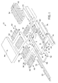
- Fig. 1 illustrates a mattress assembly 10 of the present invention.
- the mattress assembly 10 includes a bottom cover 12 having a bottom surface 14 and upwardly extending sidewall 16 surrounding bottom surface 14 to define an interior region 18. Straps 20 are coupled to bottom cover 12 for securing the mattress assembly 10 to a bed frame (not shown) if desired.
- a plurality of air cushions is configured to be located within the interior region 18 of mattress 10.
- a pair of rotation cushions 22 is located on bottom surface 14. Cushions 22 are stored in a normally deflated configuration on surface 14. Rotation cushions 22 are selectively inflated and deflated to control rotation therapy of a patient located on the mattress 10.
- Mattress 10 includes a head end 24 and a foot end 26.
- a pair of proportional valve assemblies 28 and 30 is located in interior region 18 adjacent head end 24.
- a lower head cushion 32 is located within interior region 18 adjacent head end 24.
- Lower body cushions 34 and 36 are located in the interior region 18 spaced toward the foot end 26 from lower head bladder 32.
- Support surface bladders 38 are located on top of bladders 32, 34, and 36 within interior region 18.
- Support surface cushions 38 include a head cushion 40, a chest cushion 42, a seat cushion 44, and a foot cushion 46.
- Support cushions 40, 44, and 46 include inner bladder sections 48 and outer bladder sections 50 and 51 which are separately controllable from an air supply source as discussed below.
- Cloth tube 58 includes a first end 62 coupled to an outlet 57 of the manifold of valve 56 and a second end 64 coupled to a manifold inlet 66 of valve 28.
- Cloth tube 60 has a first end 68 coupled to an outlet 69 of the manifold of valve 56 and a second end 70 coupled to a manifold inlet 72 of valve 30 as shown in Fig. 3.
- a mesh tube liner is located within and extends the length of each of the cloth tubes 58 and 60 to permit a vacuum to be applied to the tubes 58 and 60 to deflate the air bladders rapidly as discussed below.
- the cloth tubes 58 and 60 are illustratively two-inch (5.08 cm) diameter tubes which transfer air from the blower unit 52 to the valve assemblies 28 and 30. Cloth tubes 58 and 60 are very flexible and reduce the likelihood of kinking when moved or articulated with the mattress assembly 10 compared to conventional plastic tubes.
- Mattress assembly 10 further includes width extension cushions 74, 76, 78, and 80 which are positioned outside bottom cover 12. Cushions 74 and 78 are located on opposite sides of the mattress assembly 10 near head end 24. Cushions 76 and 80 are located on opposite sides of the mattress assembly 10 near foot end 26. As best illustrated in Fig. 2, the width extension cushions 74, 76, 78, and 80 are all coupled together and coupled to a valve 82 located near foot end 26 of mattress assembly 10. Width extension cushions 74, 76, 78, and 80 are normally inflated during operation of the mattress assembly 10. However, valve 82 may be manually opened to release air from the width extension cushions 74, 76, 78, and 80 to permit the mattress assembly 10 to be moved to a narrower frame.
- the width extension bladders 74, 76, 78, and 80 are inflated. Therefore, the mattress assembly 10 can be used on frames having various widths without creating a gap between siderails of the frame and the edges of the mattress assembly 10.
- Med/Surg frames are wider frames.
- Critical care frames are typically narrower frames. Therefore, mattress assembly 10 can be used on both Med/Surg frames and critical care frames by manually opening and closing valve 82.
- top cover 84 is located all over the side wall 16 of bottom cover 12.
- Top cover 84 is illustratively a washable cover. The remainder of the cushions, hoses, and bottom cover are wipable for cleaning.
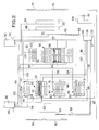
- Fig. 2 illustrates air flow between the valves and various cushions of the mattress assembly 10.
- Rotation bladders 22 are coupled to valves 28 and 30 by air supply lines 88 and 90, respectively.
- Lower head cushion 32 is coupled to line 106 from valve 30.
- Lower body cushions 34 and 36 include internal bladders 94 and 96, respectively, which are each coupled to a supply line 92 from valve 30.
- air is supplied through supply line 92 to inflate the internal bladders 94 and 96 automatically to a predetermined pressure to reduce the likelihood that a patient will bottom out against a bed frame.
- Internal bladders 94 and 96 are surrounded by external bladders of lower body cushions 34 and 36.
- the external bladders of cushions 34 and 36 are coupled to outlets of valves 28 and 30 by supply lines 98 and 100, respectively. Therefore, external bladders of cushions 34 and 36 can be controlled by lines 98 and 100 while the internal bladders 94 and 96 remain inflated by supply line 92.
- Central section 48 of head support surface cushion 40 is coupled to an outlet of valve 28 by line 102.
- Opposite side sections 50 and 51 of head support surface cushion 40 are coupled to valves 28 and 30 by lines 104 and 106, respectively.
- Chest support surface cushion 42 is coupled to valve 28 by line 108.
- Chest support surface cushion includes internal percussion/vibration (P/V) bladders 110, 112, and 114.
- P/V bladder 110 is coupled to a first outlet of P/V valve 56 by line 116.
- P/V bladder 112 is coupled to a second outlet of P/V valve 56 by line 118.
- P/V bladder 114 is coupled to a third outlet of P/V valve 56 by line 120.
- Opposite side sections 50 and 51 of foot support surface cushion 46 are coupled to supply lines 104 and 106 of valves 28 and 30, respectively.
- Central section 48 of foot support surface cushion 46 is coupled to valve assembly 30 by supply line 124.
- Supply line 104 from valve 28 is also coupled to an inlet of valve 82.
- An outlet of valve 82 is coupled to width extension cushions 74, 76, 78, and 80 as discussed above.
- Outlet line 125 is a vent hose.
- valves 28 and 30 are actuated to deflate the inner sections 48 of cushions 40, 44, and 46 to a reduced pressure compared to outer sections 50 and 51.
- the outer sections 50 and 51 of cushions 40, 44, and 46 remain inflated.
- Cushions 34 and 35 remain inflated. This helps cradle the patient to maintain the patient on the mattress assembly 10 during transport of the bed.
- valves 28, 30, and 56 Details of the valves 28, 30, and 56 are disclosed in U.S. application Serial No. 09/093,303, entitled VALVE ASSEMBLY,
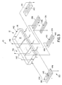
- Fig. 3 illustrates a plurality of transfer plates 130 which are coupled to bottom surface 14 of bottom cover 16 to facilitate transfer of the mattress assembly 10 from one bed frame to another bed frame.
- Transfer plates 130 include a foot plate 132, a thigh plate 134, a seat plate 136, a chest plate 138, and a head plate 140.
- Plates 132, 134, 136, 138, and 140 are each formed from a low friction plastic material. Plates are mounted to bottom surface 14 with suitable fasteners such as screws 142. It is understood that a plurality of fasteners 142 is used to couple each transfer plate 132, 134, 136, 138, and 140 to the bottom cover 10.
- Each plate 132 , 134, 136, 138, and 140 is formed to include a pair of apertures 144 which provide handle grips to facilitate transfer of the mattress assembly 10.
- Each plate 132, 134, 136, 138, and 140 is also formed to include a plurality of elongated apertures 145.
- the transfer plates 130 are used to reduce the friction while sliding the mattress assembly 10 from one bed frame to another to permit transfer without disrupting a patient lying on the mattress assembly 10.
- Blower assembly 52 is configured to hang on to a foot board 146 of a bed 148 as shown in Fig. 4.
- the blower assembly 52 includes a handle 150 and a touch screen control display 152.
- the touch screen control display 152 permits an operator to control operation of the blower 52 and valves 28, 30, and 56 to control therapies of the mattress assembly 10.
- a main microprocessor of the assembly is included within the blower housing.
- a blower motor and a power supply are located within the blower housing.
- Manifold 154 is configured to reduce air intake noise into blower assembly 52.
- Manifold 154 includes a rear wall 162 defining an inlet 164 along a bottom surface of manifold 154. Pegs 166 on opposite sides if manifold 154 are configured to couple the manifold 154 to the blower housing 52 by entering slots 168 as shown in Fig. 6.
- Manifold 154 includes an internal lip 170 to retain a filter 172 in the manifold 154.
- the blower housing 52 includes a recessed portion 174 for receiving the manifold 154.
- a grate 176 permits inlet air to pass into the blower housing 152 in the direction of arrows 178.
- the grate 176 is not required. In other words, an opening can be formed in blower housing 152 without the grate 176.
- manifold 154 deflects inlet air entering the blower housing 52 in the direction of arrows 156 by an angle of 90°. This directional change reduces air intake noise.
- a layer of sound foam 180 is located along rear wall 162 to further reduce air intake noise.
- the air supply hose 160 includes air connectors 158 at each end.
- Connectors include a hose fitting 182, an outer sleeve 184, and an O-ring 186.
- a spring release 188 is provided to lock the fittings 158 in place.
- An electrical cable 190 includes electrical connectors 192 at opposite ends. Cable 190 is inserted through openings 194 and fittings 182 so that the cable 190 extends through the air tube 160 from the blower housing 52 into the inside of mattress assembly 10. Therefore, cable 190 is not exposed.
- One connector 192 is coupled to the electrical circuit of the blower assembly 52 and the other connector 192 is coupled to the electrical circuit within the mattress assembly 10. When the fittings 182 and 184 are assembled, the fittings 182 and 184 clamp the cable 190 to provide strain relief for the cable 190.
- the fitting 158 can be removed from an air outlet of the housing 52 and the manifold 154 can be removed from the air inlet of the blower housing 52.
- the fitting 158 coupled to air hose 160 is then connected to a female receptacle molded into the housing 52 at the air inlet so that air may be removed rapidly from the plurality of air cushions of the mattress assembly 10.
- the present invention includes a siderail down sensor 200 coupled to a frame 202 of bed 148.
- the siderail down sensor 200 is configured to provide an output signal over signal line 204 when the siderail 206 of bed 148 is moved downwardly in the direction of arrows 208.
- the frame includes a support member 210 movable from the position over sensor apparatus 200 when the siderail is up to the position spaced apart from sensor apparatus 200 when the siderail is down.
- Sensor 200 includes a body 212 and fasteners 214 for securing the body 212 to the frame 202.
- Sensor 200 also includes a switch 216 having an actuator arm 218 which opens and closes a switch 220 as the siderail 206 moves from its up position illustrated in Fig. 9 to the down position. In other words, when the switch 220 is open as shown in Fig. 11, an output signal is generated to indicate that the siderail 206 is down.
- certain therapies of the mattress assembly 10 are disabled. For instance, rotational therapy is discontinued upon detection of the siderail being down by sensor 200.
- a clip assembly 222 is provided for securing the sensor 224 to the siderail 206.
- the clip assembly 222 is configured to mount the sensor 224 to a support frame 226 of siderail 206.
- Clip assembly 222 includes a first body portion 228 slidably coupled to a second body portion 230. First and second body portions 228 and 230 are biased toward each other by springs 232.
- sensor 224 is a ball switch or a mercury switch.
- Angle sensors are provided within the mattress assembly 10 so that the microprocessor can determine the articulation angle for a head section 24 of the mattress assembly 10.
- a first sensor such as an accelerometer is located in a seat section of the mattress assembly 10.
- a second sensor such as an accelerometer is coupled to a bottom surface of one of the valves 28 or 30 located within the head section 24 of the mattress assembly 10.
- the seat section accelerometer provides a reference output since the seat section does not articulate. Therefore, a zero reading can be taken from the seat sensor.
- the head sensor detects such movement and compares its new position to the reference position from the sensor in the seat section.
- the seat section sensor can accommodate movement to the Trendelenburg and reverse Trendelenburg position so that the angle of the head section of the mattress relative to the seat section can always be detected during articulation of the mattress assembly 10 on a bed frame.
Abstract
Description
- The present invention relates to a mattress assembly for use on a hospital bed. More particularly, the present invention relates to a replacement mattress assembly which can be used on various types of bed frames to provide improved patient support and therapies.
- The mattress assembly of the present invention is a mattress replacement which can be used on various types of frames to provide improved patient support and therapy. The mattress includes a support surface having an external cover defining an interior region. A plurality of air cushions is located within the interior region. The interior region also includes valves located at a head end of the mattress and an air intake manifold and percussion/vibration valve at a foot end of the mattress. Cloth tubes are configured to couple the air inlet manifold to the valves at the head end of the mattress. These cloth tubes are very flexible and reduce the likelihood of kinking when the mattress is articulated on a bed frame.
- The mattress assembly is designed to facilitate transfer of the mattress assembly from one bed frame to another. A plurality of low friction plates is located on a bottom surface of the mattress. The plates are formed to include apertures and handles to facilitate movement of the mattress from one bed frame to another by a caregiver. The mattress also includes extension cushions on opposite side portions of the mattress. These cushions can be selectively inflated and deflated depending upon the width of the bed frame on which the mattress is located. Illustratively, the valve is used to selectively inflate and deflate the extension cushions.
- Also illustratively, therapy controls are input into the system using a touch screen formed integrally with a blower housing. An operator can input commands into a main microprocessor using the touch screen input display. Signals are transmitted from the main microprocessor to a valve controller within the mattress assembly using an electrical cable which extends between the housing and the controller. In the illustrated embodiment, the electrical cable extends through the interior region of an air hose connected between the blower housing and the inlet manifold within the mattress. Running the electrical cable through the interior region of the air hose reduces clutter and reduces likelihood that the electrical cable will be inadvertently disconnected.
- The mattress assembly is configured to provide various types of therapy for a patient located on the mattress. For instance, percussion vibration therapy and rotation therapy can be provided to the patient. The apparatus includes a siderail down sensor configured to be coupled to the bed frame or directly to the siderail of the bed to generate an output signal when the siderail is down. The output signal is delivered to the microprocessor to deactivate a particular therapy, such as the rotation therapy, if the siderail is down.
- According to one aspect of the present invention, an apparatus is provided for controlling inflation and deflation of an air mattress including at least one air bladder, a valve, and a controller for the valve. The apparatus includes a housing formed to include an air inlet and an air outlet, an air supply located within the housing, and an electrical user input located on the housing. The electrical input is configured to generate a control signal for the valve controller. The apparatus also includes an air hose having a first end coupled to the outlet of the housing and a second end coupled to the valve. The hose has an interior region configured to conduct air from the air supply to the valve. The apparatus further includes an electrical cable having a first end coupled to the housing and a second end coupled to the controller. The cable is located at least partially within the interior region of the hose.
- In the illustrated embodiment, the cable includes first and second electrical connectors at the first and second ends, respectively. The first electrical connector is coupled to a connector on the housing outside the interior region of the hose, and the second electrical connector is coupled to the controller outside the interior region of the hose. A center portion of the cable is located within the interior region of the hose.
- The illustrated hose includes first and second fittings at the first and second ends, respectively. The first and second fittings are configured to engage the cable to provide strain relief adjacent the first and second ends of the cable.
- The apparatus further includes an air intake manifold coupled to the air inlet. The manifold includes a wall defining a bottom opening. The manifold is configured to change the direction of intake air entering the housing to reduce the intake noise of the intake air. A filter is coupled to the air manifold. A foam material is coupled to the wall of the manifold within an interior region of the manifold.
- According to another aspect of the present invention, an air mattress includes a cover defining an interior region, at least one air bladder located in the interior region, an air manifold having an inlet configured to receive air from an air supply and an outlet, a valve having an inlet and an outlet coupled to the at least one air bladder, and a cloth tube having a first end coupled to the outlet of the manifold and a second end coupled to the inlet of the valve. The manifold, valve, and cloth tube are all located within the interior region.
- The illustrated mattress includes a plurality of air bladders and first and second valves having a plurality of outputs coupled to the plurality of air bladders. The first cloth tube extends from the manifold to the first valve. The apparatus also includes a second cloth tube having a first end coupled to the outlet of the manifold and a second end coupled to an inlet of the second valve. In the illustrated embodiment, a mesh liner is located within each cloth tube.
- According to yet another aspect of the present invention, a mattress is configured to be located on a bed frame. The mattress includes a support surface having a head end, a foot end, and spaced apart first and second side portions. The mattress also includes an air bladder coupled to and extending along the first side of the support surface. The air bladder is inflatable and deflatable to adjust the width of the mattress.
- In the illustrated embodiment, the mattress includes a second air bladder coupled to and extending along the second side portion of the support surface. The second air bladder is inflatable and deflatable to adjust the width of the mattress. The first and second air bladders are illustratively coupled to an exterior portion of the support surface.
- In the illustrated embodiment, the support surface includes a plurality of air bladders located within an interior region of the support surface and a cover surrounding the plurality of air bladders, the first and second air bladders being located outside the cover.
- Also in the illustrated embodiment, a valve is configured to be coupled to an air supply. The valve has an output coupled to the first and second air bladders for selectively inflating and deflating the first and second air bladders based on the width of the frame. The valve is configured to normally inflate the first and second air bladders. A second valve is also coupled to the first and second air bladders for manually removing air from the first and second air bladders upon actuation of the second valve.
- According to a further aspect of the present invention, a support apparatus includes a mattress having a top surface configured to support a body and a bottom surface. The apparatus also includes at least one plate coupled to the bottom surface of the mattress to facilitate transfer of the mattress from one bed frame to another bed frame.
- In the illustrated embodiment, the plate is made from a low friction plastic material. A plurality of plates is illustratively coupled to the bottom surface of the mattress. The plates have a rectangular shape and includes first and second ends located adjacent first and second side portions of the mattress. The plates are formed to include a plurality of apertures. The plates are also formed to include first and second handles adjacent the first and second ends.
- According to a still further aspect of the present invention, a replacement mattress apparatus is provided for use on a bed frame having at least one siderail movable from an up position to a down position. The apparatus includes a support surface, an electrical controller configured to control the support surface, and a siderail down sensor configured to be coupled to one of the bed frame and siderail. The siderail down sensor is electrically coupled to the controller. The siderail down sensor is configured to generate an output signal indicating that the siderail of the bed frame is in the down position.
- The siderail down sensor may include, for example, a mercury switch, a ball switch, or an accelerometer. In one illustrated embodiment, the siderail down sensor includes a switch and an attachment mechanism configured to couple the sensor to the bed frame adjacent the siderail. The siderail is configured to actuate the switch and generate an output signal as the siderail moves from an up position to a down position. The switch of the siderail down sensor is configured to be closed when the siderail is in the up position.
- In another illustrated embodiment, the siderail down sensor includes first and second plates slidable relative to each other. The first and second plates are spring biased together to clamp the siderail down sensor to the siderail.
- According to an additional embodiment of the present invention, a mattress includes a support surface having a head end, a foot end, and spaced apart first and second side portions. The support surface includes at least one air cushion having separately inflatable first and second outer sections located adjacent the first and second side portions of the support surface, respectively, and an inner section located between the first and second outer sections. The mattress also includes a valve having an air inlet configured to be coupled to an air supply, and at least two outlets coupled to the first and second outer sections and the inner section. The mattress further includes a controller coupled to the valve. The controller is configured to reduce the pressure of the inner section of the air cushion to a pressure less than a pressure in the first and second outer sections to maintain a body on the support surface positioned over the inner portion during transport of the support surface.
- In the illustrated embodiment, the support surface includes a head cushion, a seat cushion, and a foot cushion which each include the first and second outer sections and the inner sections which are separately inflatable. A chest cushion is located between the head cushion and the seat cushion. The chest cushion is formed to include a plurality of percussion/vibration bladders coupled to a percussion/vibration valve.
- Also in the illustrated embodiment, the support surface includes at least one lower air cushion situated below the head cushion, the seat cushion, and the foot cushion within the support surface. The at least one lower air cushion remains inflated during deflation of the inner sections during transport.
- First and second rotation bladders are located below the at least one lower air cushion within the support surface. The first and second rotation bladders are coupled to outputs from the valve. The controller is configured to inflate and deflate the rotation bladders to provide rotation therapy to the body on the support surface.
- Additional objects, features, and advantages of the invention will become apparent to those skilled in the art upon consideration of the following detailed description of the preferred embodiment exemplifying the best mode of carrying out the invention as presently perceived.
- The detailed description particularly refers to the accompanying figures in which:
- Fig. 1 is an exploded perspective view of the mattress assembly of the present invention illustrating a plurality of air cushions, air tubes, and control valves located between top and bottom covers;
- Fig. 2 is a diagrammatical view illustrating connection between the valves and the air cushions of the present invention;
- Fig. 3 is an exploded perspective view illustrating a bottom cover and a plurality of low friction plastic transfer plates configured to be coupled to the bottom cover to facilitate transfer of the mattress assembly from one bed frame to another;
- Fig. 4 is a perspective view illustrating a blower housing coupled to a foot board of a bed for supplying air to the mattress assembly;
- Fig. 5 is a sectional view taken along lines 5-5 of Fig. 4 illustrating an air intake manifold coupled to the blower housing;
- Fig. 6 is a partial sectional view illustrating a slot formed in the blower housing for receiving a corresponding pin formed on the air intake manifold;
- Fig. 7 is a perspective view illustrating further details of the air intake manifold;
- Fig. 8 is an exploded perspective view illustrating details of an air hose assembly extending between the blower housing and the mattress assembly which includes an internal electrical cord for transmitting control signals from the blower housing control panel to the mattress assembly;
- Fig. 9 is a partial side elevational view illustrating a siderail of a bed and a siderail down sensor coupled to a frame below the siderail;
- Fig. 10 is an enlarged side elevational view illustrating a switch of the siderail down sensor which is closed when the siderail is in its upwardly pivoted position;
- Fig. 11 is a side elevational view similar to Fig. 10 illustrating the sensor switch in an open position when the siderail is pivoted downwardly;
- Fig. 12 is a sectional view taken through another embodiment of the siderail down indicator which clips on a frame member of the siderail; and
- Fig. 13 is a side elevational view of the siderail down indicator of Fig. 12.
-
- Referring now to the drawings, Fig. 1 illustrates a
mattress assembly 10 of the present invention. Themattress assembly 10 includes abottom cover 12 having abottom surface 14 and upwardly extendingsidewall 16 surroundingbottom surface 14 to define aninterior region 18.Straps 20 are coupled tobottom cover 12 for securing themattress assembly 10 to a bed frame (not shown) if desired. - A plurality of air cushions is configured to be located within the
interior region 18 ofmattress 10. A pair of rotation cushions 22 is located onbottom surface 14.Cushions 22 are stored in a normally deflated configuration onsurface 14. Rotation cushions 22 are selectively inflated and deflated to control rotation therapy of a patient located on themattress 10. -
Mattress 10 includes ahead end 24 and afoot end 26. A pair ofproportional valve assemblies interior region 18adjacent head end 24. Alower head cushion 32 is located withininterior region 18adjacent head end 24. Lower body cushions 34 and 36 are located in theinterior region 18 spaced toward thefoot end 26 fromlower head bladder 32. -
Support surface bladders 38 are located on top ofbladders interior region 18. Support surface cushions 38 include ahead cushion 40, achest cushion 42, aseat cushion 44, and afoot cushion 46. Support cushions 40, 44, and 46 includeinner bladder sections 48 andouter bladder sections - Air enters the mattress assembly from a
blower 52 throughinlet 54.Inlet 54 is coupled to aninlet 55 of a percussion/vibration valve 56. Air supply throughinlet 54 is also coupled tovalves cloth tubes Cloth tube 58 includes afirst end 62 coupled to anoutlet 57 of the manifold ofvalve 56 and asecond end 64 coupled to amanifold inlet 66 ofvalve 28.Cloth tube 60 has afirst end 68 coupled to anoutlet 69 of the manifold ofvalve 56 and asecond end 70 coupled to amanifold inlet 72 ofvalve 30 as shown in Fig. 3. A mesh tube liner is located within and extends the length of each of thecloth tubes tubes - The
cloth tubes blower unit 52 to thevalve assemblies Cloth tubes mattress assembly 10 compared to conventional plastic tubes. -
Mattress assembly 10 further includes width extension cushions 74, 76, 78, and 80 which are positioned outsidebottom cover 12.Cushions mattress assembly 10 nearhead end 24.Cushions mattress assembly 10 nearfoot end 26. As best illustrated in Fig. 2, the width extension cushions 74, 76, 78, and 80 are all coupled together and coupled to avalve 82 located nearfoot end 26 ofmattress assembly 10. Width extension cushions 74, 76, 78, and 80 are normally inflated during operation of themattress assembly 10. However,valve 82 may be manually opened to release air from the width extension cushions 74, 76, 78, and 80 to permit themattress assembly 10 to be moved to a narrower frame. In other words, when a wide frame is used, thewidth extension bladders mattress assembly 10 can be used on frames having various widths without creating a gap between siderails of the frame and the edges of themattress assembly 10. Typically, Med/Surg frames are wider frames. Critical care frames are typically narrower frames. Therefore,mattress assembly 10 can be used on both Med/Surg frames and critical care frames by manually opening and closingvalve 82. - A
top cover 84 is located all over theside wall 16 ofbottom cover 12.Top cover 84 is illustratively a washable cover. The remainder of the cushions, hoses, and bottom cover are wipable for cleaning. - Fig. 2 illustrates air flow between the valves and various cushions of the
mattress assembly 10.Rotation bladders 22 are coupled tovalves air supply lines Lower head cushion 32 is coupled toline 106 fromvalve 30. Lower body cushions 34 and 36 includeinternal bladders supply line 92 fromvalve 30. When operation of the mattress assembly is initiated, air is supplied throughsupply line 92 to inflate theinternal bladders Internal bladders cushions valves supply lines 98 and 100, respectively. Therefore, external bladders ofcushions lines 98 and 100 while theinternal bladders supply line 92. -
Central section 48 of headsupport surface cushion 40 is coupled to an outlet ofvalve 28 byline 102. Oppositeside sections support surface cushion 40 are coupled tovalves lines - Chest
support surface cushion 42 is coupled tovalve 28 byline 108. Chest support surface cushion includes internal percussion/vibration (P/V) bladders 110, 112, and 114. P/V bladder 110 is coupled to a first outlet of P/V valve 56 byline 116. P/V bladder 112 is coupled to a second outlet of P/V valve 56 byline 118. P/V bladder 114 is coupled to a third outlet of P/V valve 56 byline 120. -
Side portions support surface cushion 44 are coupled tolines valves Central portion 48 of seatsupport surface cushion 44 is coupled tovalve 30 byline 122. - Opposite
side sections support surface cushion 46 are coupled to supplylines valves Central section 48 of footsupport surface cushion 46 is coupled tovalve assembly 30 bysupply line 124.Supply line 104 fromvalve 28 is also coupled to an inlet ofvalve 82. An outlet ofvalve 82 is coupled to width extension cushions 74, 76, 78, and 80 as discussed above.Outlet line 125 is a vent hose. - If it is desired to transport a bed with a patient on the
mattress assembly 10, thevalves inner sections 48 ofcushions outer sections outer sections cushions Cushions 34 and 35 remain inflated. This helps cradle the patient to maintain the patient on themattress assembly 10 during transport of the bed. - Details of the
valves - Fig. 3 illustrates a plurality of
transfer plates 130 which are coupled tobottom surface 14 ofbottom cover 16 to facilitate transfer of themattress assembly 10 from one bed frame to another bed frame.Transfer plates 130 include afoot plate 132, athigh plate 134, aseat plate 136, achest plate 138, and ahead plate 140.Plates bottom surface 14 with suitable fasteners such as screws 142. It is understood that a plurality offasteners 142 is used to couple eachtransfer plate bottom cover 10. It is also understood that other suitable fasteners such as rivets, snaps, etc., may be used for theplates 130. Eachplate apertures 144 which provide handle grips to facilitate transfer of themattress assembly 10. Eachplate elongated apertures 145. Thetransfer plates 130 are used to reduce the friction while sliding themattress assembly 10 from one bed frame to another to permit transfer without disrupting a patient lying on themattress assembly 10. -
Blower assembly 52 is configured to hang on to afoot board 146 of abed 148 as shown in Fig. 4. Theblower assembly 52 includes ahandle 150 and a touchscreen control display 152. The touchscreen control display 152 permits an operator to control operation of theblower 52 andvalves mattress assembly 10. A main microprocessor of the assembly is included within the blower housing. In addition, a blower motor and a power supply are located within the blower housing. - Air enters the
blower housing 52 throughintake manifold 154 in the direction ofarrows 156. Air exitsblower assembly 52 throughoutlet connector 158 and passes throughair hose 160 to the inlet of manifold ofvalve 56.Manifold 154 is configured to reduce air intake noise intoblower assembly 52.Manifold 154 includes arear wall 162 defining aninlet 164 along a bottom surface ofmanifold 154.Pegs 166 on opposite sides ifmanifold 154 are configured to couple the manifold 154 to theblower housing 52 by enteringslots 168 as shown in Fig. 6. -
Manifold 154 includes aninternal lip 170 to retain afilter 172 in themanifold 154. In the illustrated embodiment, theblower housing 52 includes a recessedportion 174 for receiving themanifold 154. Agrate 176 permits inlet air to pass into theblower housing 152 in the direction ofarrows 178. Thegrate 176 is not required. In other words, an opening can be formed inblower housing 152 without thegrate 176. - As best illustrated in Fig. 5,
manifold 154 deflects inlet air entering theblower housing 52 in the direction ofarrows 156 by an angle of 90°. This directional change reduces air intake noise. A layer ofsound foam 180 is located alongrear wall 162 to further reduce air intake noise. - Another feature is illustrated in Fig. 8. The
air supply hose 160 includesair connectors 158 at each end. Connectors include a hose fitting 182, anouter sleeve 184, and an O-ring 186. Aspring release 188 is provided to lock thefittings 158 in place. Anelectrical cable 190 includeselectrical connectors 192 at opposite ends.Cable 190 is inserted throughopenings 194 andfittings 182 so that thecable 190 extends through theair tube 160 from theblower housing 52 into the inside ofmattress assembly 10. Therefore,cable 190 is not exposed. Oneconnector 192 is coupled to the electrical circuit of theblower assembly 52 and theother connector 192 is coupled to the electrical circuit within themattress assembly 10. When thefittings fittings cable 190 to provide strain relief for thecable 190. - If it is desired to quickly deflate the plurality of air cushions within the
mattress assembly 10, the fitting 158 can be removed from an air outlet of thehousing 52 and the manifold 154 can be removed from the air inlet of theblower housing 52. The fitting 158 coupled toair hose 160 is then connected to a female receptacle molded into thehousing 52 at the air inlet so that air may be removed rapidly from the plurality of air cushions of themattress assembly 10. - Another feature is illustrated in Figs. 9-13. The present invention includes a siderail down
sensor 200 coupled to aframe 202 ofbed 148. The siderail downsensor 200 is configured to provide an output signal oversignal line 204 when thesiderail 206 ofbed 148 is moved downwardly in the direction ofarrows 208. - As illustrated in the enlarged views in Figs. 10 and 11, the frame includes a
support member 210 movable from the position oversensor apparatus 200 when the siderail is up to the position spaced apart fromsensor apparatus 200 when the siderail is down.Sensor 200 includes abody 212 andfasteners 214 for securing thebody 212 to theframe 202.Sensor 200 also includes aswitch 216 having anactuator arm 218 which opens and closes aswitch 220 as thesiderail 206 moves from its up position illustrated in Fig. 9 to the down position. In other words, when theswitch 220 is open as shown in Fig. 11, an output signal is generated to indicate that thesiderail 206 is down. When the controller receives a siderail down signal fromsensor 200, certain therapies of themattress assembly 10 are disabled. For instance, rotational therapy is discontinued upon detection of the siderail being down bysensor 200. - Another embodiment of the siderail down sensor is illustrated in Figs. 12 and 13. In this embodiment, a
clip assembly 222 is provided for securing thesensor 224 to thesiderail 206. Specifically, theclip assembly 222 is configured to mount thesensor 224 to asupport frame 226 ofsiderail 206.Clip assembly 222 includes afirst body portion 228 slidably coupled to asecond body portion 230. First andsecond body portions springs 232. Illustratively,sensor 224 is a ball switch or a mercury switch. - Angle sensors are provided within the
mattress assembly 10 so that the microprocessor can determine the articulation angle for ahead section 24 of themattress assembly 10. A first sensor such as an accelerometer is located in a seat section of themattress assembly 10. A second sensor such as an accelerometer is coupled to a bottom surface of one of thevalves head section 24 of themattress assembly 10. The seat section accelerometer provides a reference output since the seat section does not articulate. Therefore, a zero reading can be taken from the seat sensor. As the head of the bed is articulated, the head sensor detects such movement and compares its new position to the reference position from the sensor in the seat section. The seat section sensor can accommodate movement to the Trendelenburg and reverse Trendelenburg position so that the angle of the head section of the mattress relative to the seat section can always be detected during articulation of themattress assembly 10 on a bed frame.
Claims (35)
- A support apparatus comprising a support surface including a head end, a foot end and spaced apart first and second side portions, and an air bladder coupled to and extending along the first side portion of the support surface, the bladder being inflatable and deflatable to adjust a width of the support apparatus.
- The apparatus as claimed in claim 1 wherein a second air bladder is coupled to and extends along the second side portion, the second air bladder being inflatable and deflatable to adjust the width of the support apparatus.
- The apparatus as claimed in claim 2, wherein the first and second air bladders are coupled to an exterior portion of the support surface.
- The apparatus as claimed in either claim 2 or claim 3 wherein the support surface includes a plurality of air bladders located within an interior region of the support surface and a cover surrounding the plurality of air bladders, the first and second air bladders being located outside the cover.
- The apparatus as claimed in claim 4 further comprising an air manifold having an inlet configured to receive air from an air supply and an outlet and a cloth tube having a first end coupled to the outlet of the manifold and a second end, the manifold and cloth tube being located within the interior region of the support surface.
- The apparatus as claimed in claim 5 further comprising first and second valves having a plurality of outputs coupled to the plurality of air bladders, the cloth tube extending from the manifold to the first valve, and further comprising a second cloth tube having a first end coupled to the outlet of the manifold and a second end coupled to an inlet of the second valve.
- The apparatus as claimed in any one of claims 2 to 6 further including a valve configured to be coupled to an air supply, the valve having an output coupled to the first and second air bladders for selectively inflating and deflating the first and second air bladders.
- The apparatus as claimed in claim 7 wherein the valve is configured to normally inflate the first and second air bladders and a second valve is provided coupled to the first and second air bladders for manually removing air from the first and second air bladders upon actuation of the second valve.
- The apparatus as claimed in claim 1 wherein the support surface includes at least one support member located within an interior region of the support surface and a cover surrounding the at least one support member, wherein the bladder is located outside the cover, and wherein the apparatus further comprises an air system coupled to the bladder to supply air to the bladder.
- The apparatus as claimed in claim 9 further comprising a valve positioned outside the cover and configured to permit deflation of the bladder.
- The apparatus as claimed in either claim 9 or claim 10 wherein the support member of the support surface is normally inflated to provide support when the bladder is deflated to adjust the width of the support apparatus.
- The support apparatus as claimed in any one of claims 9 to 11 further comprising another bladder positioned outside the cover on a side opposite the other bladder.
- The apparatus of claim 1 further comprising an air supply and a valve coupled to the air supply, the valve having an output coupled to the bladder to selectively inflate and deflate the bladder.
- The apparatus as claimed in claim 13 wherein the valve is in a first position when the support apparatus is positioned on a bed frame having a first width and the valve is movable to a second position when the support apparatus is positioned on a bed frame having a second width less than the first width to permit deflation of the bladder.
- The apparatus of claim 13 or claim 14 further comprising another bladder coupled to the outlet of the valve to permit selective inflation and deflation of said another bladder.
- The apparatus as claimed in claim 15 wherein the bladders are positioned on opposite side portions of the support surface.
- The apparatus as claimed in claim 1 wherein the support surface defines a continuous interior volume and includes a plurality of bladders positioned in the continuous interior volume and a cover surrounding the plurality of bladders, and wherein the bladder is located outside the cover.
- The apparatus as claimed in claim 17 wherein the plurality of bladders extend transversely and the bladder extends longitudinally.
- The apparatus as claimed in claim 18 further comprising a second bladder positioned along the second side portion of the support surface and being inflatable and deflatable to adjust the width of the support apparatus.
- The apparatus as claimed in claim 19 further comprising an air system coupled to the first and second bladders to supply air to the bladders.
- The apparatus as claimed in claim 20 wherein the air system is coupled to the plurality of bladders to supply air to the plurality of bladders.
- A support system apparatus comprising a plurality of bed frames having decks of different widths, and a support apparatus as claimed in claim 1, wherein the bladder is inflatable to define a first width of the support apparatus sized to fit on a deck of a first bed of the plurality of beds and deflatable to adjust to a second width sized to fit on a deck of a second bed of the plurality of beds having a smaller width than the first width of the deck of the first bed, the second width of the support apparatus being less than the first width of the support apparatus.
- The support system apparatus as claimed in claim 22 wherein the bladder is normally inflated when positioned on the deck of the first bed and normally deflated when positioned on the deck of the second bed.
- The support system apparatus as claimed in claim 23 wherein the support surface includes at least one support bladder located within an interior region of the support surface, the at least one support bladder is normally inflated when the bladder is inflated and deflated.
- The support system apparatus as claimed in claim 24 wherein the support apparatus further includes a valve configured to permit deflation of the bladder to the second width.
- The support system apparatus as claimed in any one of claims 22 to 25 wherein the support apparatus further includes another bladder positioned along the first side portion of the support surface.
- The support system apparatus as claimed in any one of claims 22 to 26 wherein the support apparatus further includes another bladder positioned along the second side portion of the support surface to cooperate with the other bladder to define the first width when inflated and the second width when deflated.
- A support system apparatus comprising a plurality of beds having bed frames of different widths and a support apparatus as claimed in claim 1, the support surface and the bladder cooperating to define a width of the support apparatus that is adjustable depending on the width of the bed frame upon which the support apparatus is positioned, the bladder being normally deflated when the support apparatus is positioned on a first bed of the plurality of beds having a first width to reduce the width of the support surface, the bladder being normally inflated when the support apparatus is positioned on a second bed frame of the plurality of beds having a second width greater than the first width of the first bed frame to increase the width of the support apparatus.
- The support system apparatus as claimed in claim 28 wherein the support apparatus further includes another bladder configured to inflate and deflate and being positioned adjacent to the support surface on an opposite side of support surface from the other bladder, wherein the bladders cooperate with the support surface to define the first width when deflated and cooperate to define the second width when inflated.
- The support system apparatus as claimed in claim 29 wherein the support apparatus further includes a valve configured to permit simultaneous deflation of the bladders when positioned in the first bed frame.
- The support system apparatus as claimed in any one of claims 28 to 30 wherein the support surface includes a cover defining an interior region and a plurality of normally inflated bladders positioned in the interior region, the bladder being positioned outside the cover.
- The apparatus as claimed in any preceding claim wherein the support surface has a top surface configured to support a body and a bottom surface, and further comprising at least one plate coupled to the bottom surface to facilitate transfer of the mattress from one bed frame to another bed frame.
- The apparatus as claimed in claim 32 wherein at least one handle is formed on the plate.
- The apparatus as claimed in either claim 32 or claim 33 wherein a plurality of plates is coupled to the bottom surface of the support surface, the plates including a head plate, a foot plate, a chest plate, a thigh plate, and a seat plate.
- The apparatus as claimed in any preceding claim wherein the support surface is configured to be a replacement mattress apparatus for use on a bed frame having at least one siderail movable from an up position to a down position, the apparatus further comprising an electrical controller configured to control the support surface, and a siderail down sensor configured to be coupled to one of the bed frame and siderail, the siderail down sensor being electrically coupled to the controller, the siderail down sensor being configured to generate an output signal indicating that the siderail of the bed frame is in the down position.
Applications Claiming Priority (3)
| Application Number | Priority Date | Filing Date | Title |
|---|---|---|---|
| US08/917,145 US6021533A (en) | 1997-08-25 | 1997-08-25 | Mattress apparatus having a siderail down sensor |
| US917145 | 1997-08-25 | ||
| EP98935870A EP1011391B1 (en) | 1997-08-25 | 1998-07-22 | Mattress assembly |
Related Parent Applications (2)
| Application Number | Title | Priority Date | Filing Date |
|---|---|---|---|
| EP98935870A Division EP1011391B1 (en) | 1997-08-25 | 1998-07-22 | Mattress assembly |
| EP98935870.0 Division | 1998-07-22 |
Publications (3)
| Publication Number | Publication Date |
|---|---|
| EP1234565A2 true EP1234565A2 (en) | 2002-08-28 |
| EP1234565A3 EP1234565A3 (en) | 2002-12-18 |
| EP1234565B1 EP1234565B1 (en) | 2010-04-07 |
Family
ID=25438400
Family Applications (2)
| Application Number | Title | Priority Date | Filing Date |
|---|---|---|---|
| EP98935870A Expired - Lifetime EP1011391B1 (en) | 1997-08-25 | 1998-07-22 | Mattress assembly |
| EP02076709A Expired - Lifetime EP1234565B1 (en) | 1997-08-25 | 1998-07-22 | Mattress assembly |
Family Applications Before (1)
| Application Number | Title | Priority Date | Filing Date |
|---|---|---|---|
| EP98935870A Expired - Lifetime EP1011391B1 (en) | 1997-08-25 | 1998-07-22 | Mattress assembly |
Country Status (11)
| Country | Link |
|---|---|
| US (7) | US6021533A (en) |
| EP (2) | EP1011391B1 (en) |
| JP (1) | JP2001513384A (en) |
| AT (2) | ATE463224T1 (en) |
| AU (1) | AU8503598A (en) |
| BR (1) | BR9811375A (en) |
| CA (1) | CA2301609A1 (en) |
| DE (2) | DE69808941T2 (en) |
| IL (1) | IL134668A0 (en) |
| TW (1) | TW404829B (en) |
| WO (1) | WO1999009865A1 (en) |
Cited By (6)
| Publication number | Priority date | Publication date | Assignee | Title |
|---|---|---|---|---|
| US10188569B2 (en) | 2013-09-06 | 2019-01-29 | Stryker Corporation | Patient support usable with bariatric patients |
| US10660809B2 (en) | 2015-09-11 | 2020-05-26 | Stryker Corporation | Telescoping assembly for use on a patient support apparatus |
| US10842701B2 (en) | 2016-10-14 | 2020-11-24 | Stryker Corporation | Patient support apparatus with stabilization |
| US10842694B2 (en) | 2013-09-06 | 2020-11-24 | Stryker Corporation | Patient support usable with bariatric patients |
| US11013650B2 (en) | 2017-12-19 | 2021-05-25 | Stryker Corporation | Patient transport apparatus with movable head section |
| US11484450B2 (en) | 2018-10-08 | 2022-11-01 | Stryker Corporation | Patient support apparatus having bearing arrangement for deck extension assembly |
Families Citing this family (128)
| Publication number | Priority date | Publication date | Assignee | Title |
|---|---|---|---|---|
| US6212714B1 (en) * | 1995-01-03 | 2001-04-10 | Hill-Rom, Inc. | Hospital bed and mattress having a retracting foot section |
| US6499167B1 (en) | 1995-08-04 | 2002-12-31 | Hill-Rom Services, Inc. | Mattress section support |
| US6584628B1 (en) | 1995-08-04 | 2003-07-01 | Hill-Rom Services, Inc. | Hospital bed having a rotational therapy device |
| CA2299356A1 (en) * | 1997-08-08 | 1999-02-18 | Hill-Rom, Inc. | Proning bed |
| US6021533A (en) * | 1997-08-25 | 2000-02-08 | Hill-Rom, Inc. | Mattress apparatus having a siderail down sensor |
| EP1100425A4 (en) * | 1998-06-26 | 2002-10-16 | Hill Rom Co Inc | Proning bed |
| US7834768B2 (en) | 1999-03-05 | 2010-11-16 | Hill-Rom Services, Inc. | Obstruction detection apparatus for a bed |
| EP1194105A1 (en) * | 1999-04-21 | 2002-04-10 | Hill-Rom Services, Inc. | Proning bed |
| CA2373987A1 (en) * | 1999-07-06 | 2001-01-11 | Hill-Rom Services, Inc. | Mattress assembly |
| US6689077B2 (en) | 1999-08-10 | 2004-02-10 | Reza R. Dabir | Apparatus and method for pressure management having temperature controlled air flow |
| US6658680B2 (en) | 1999-12-29 | 2003-12-09 | Hill-Rom Services, Inc. | Hospital bed |
| BR0108131A (en) | 2000-02-07 | 2004-12-07 | Hill Rom Services Inc | Device configured to be located on a patient support frame |
| WO2001062151A1 (en) | 2000-02-23 | 2001-08-30 | Hill-Rom Services, Inc. | Bed latch position detector and method |
| US6561047B1 (en) * | 2001-07-03 | 2003-05-13 | Dreamwell, Ltd. | Method and system for analyzing motion transferred to a subject on a sleeping surface |
| ATE409449T1 (en) * | 2001-10-02 | 2008-10-15 | Hill Rom Services Inc | INTEGRATED BARRIER AND FLUID SUPPLY FOR A HOSPITAL BED |
| US20030167568A1 (en) * | 2001-12-20 | 2003-09-11 | Brooke Jason C. | Bed siderails |
| US6859967B2 (en) | 2002-02-22 | 2005-03-01 | Samuel W. Harrison | Overlay mattress |
| DE60336603D1 (en) * | 2002-02-28 | 2011-05-12 | Gaymar Ind Inc | Self-adjusting upholstery device |
| EP1545345A1 (en) | 2002-08-08 | 2005-06-29 | Hill-Rom Services, Inc. | Mattress |
| EP2181685B1 (en) | 2002-09-06 | 2014-05-14 | Hill-Rom Services, Inc. | Hospital bed with controlled inflatable portion of patient support |
| CA2504763C (en) * | 2002-11-12 | 2008-06-03 | Gray Tek, Inc. | Material mover having a fluid film reservoir |
| EP1562459B1 (en) | 2002-11-18 | 2007-06-06 | CHAFFEE, Robert B. | Inflatable device |
| WO2004054408A2 (en) * | 2002-12-13 | 2004-07-01 | Cosco Management, Inc. | Bed rail |
| US7322947B2 (en) * | 2003-03-26 | 2008-01-29 | Gaymar Industries, Inc. | Vibrational and pulsating cushioning device |
| US20080092295A1 (en) * | 2003-03-26 | 2008-04-24 | Gaymar Industries, Inc. | Vibrational and Pulsating Cushioning Device |
| MXPA06002900A (en) * | 2003-09-15 | 2006-06-14 | Igt Reno Nev | Multi-player bingo game with game-winning award selection. |
| US7883478B2 (en) * | 2004-04-30 | 2011-02-08 | Hill-Rom Services, Inc. | Patient support having real time pressure control |
| EP2250988A3 (en) * | 2004-04-30 | 2011-11-30 | Hill-Rom Services, Inc. | Patient support with motion monitor device |
| US7469436B2 (en) * | 2004-04-30 | 2008-12-30 | Hill-Rom Services, Inc. | Pressure relief surface |
| US7319386B2 (en) | 2004-08-02 | 2008-01-15 | Hill-Rom Services, Inc. | Configurable system for alerting caregivers |
| US7464425B2 (en) * | 2004-08-04 | 2008-12-16 | Hill-Rom Services, Inc. | Hospital bed |
| US7260860B2 (en) | 2004-08-04 | 2007-08-28 | Hill-Rom Services, Inc. | Mattress system for a hospital bed |
| US8650686B2 (en) * | 2004-11-18 | 2014-02-18 | Anodyne Medical Device, Inc. | Adjustable width bariatric transport support surface |
| US20060117482A1 (en) * | 2004-12-07 | 2006-06-08 | Branson Gregory W | Touch screen control for lateral rotation of a hospital bed mattress |
| EP1671563B1 (en) * | 2004-12-15 | 2008-02-13 | Hill-Rom Services, Inc. | Connector apparatus for an air mattress |
| US9125777B2 (en) | 2005-01-14 | 2015-09-08 | Sage Products, Llc | Body transport apparatus |
| US7114204B2 (en) * | 2005-01-14 | 2006-10-03 | Smart Medical Technology, Inc. | Method and apparatus for transferring patients |
| US9241580B2 (en) | 2005-01-14 | 2016-01-26 | Sage Products, Llc | Body transport apparatus with integrated handles |
| US7735164B1 (en) | 2005-01-14 | 2010-06-15 | Smart Medical Technology, Inc. | Disposable patient transfer mattress |
| US8276222B1 (en) | 2005-01-14 | 2012-10-02 | Smart Medical Technology, Inc. | Patient transfer kit |
| CA2505102A1 (en) * | 2005-03-07 | 2006-09-07 | Hill-Rom Services, Inc. | Footboard for a hospital bed |
| CA2505083A1 (en) * | 2005-03-07 | 2006-09-07 | Hill-Rom Services, Inc. | Siderails for a hospital bed |
| WO2006116859A1 (en) * | 2005-05-04 | 2006-11-09 | Stryker Canadian Management Inc. | Vibrating patient support apparatus with a resonant referencing percussion device |
| WO2007008830A2 (en) | 2005-07-08 | 2007-01-18 | Hill-Rom, Inc. | Pressure control for a hospital bed |
| JP5231222B2 (en) | 2005-07-08 | 2013-07-10 | ヒル−ロム サービシーズ,インコーポレイティド | Patient support control unit |
| EP1901635B1 (en) * | 2005-07-08 | 2013-05-01 | Hill-Rom Services, Inc. | Patient support |
| US7536739B2 (en) * | 2005-08-10 | 2009-05-26 | Kreg Medical, Inc. | Therapeutic mattress |
| US7266852B2 (en) * | 2005-10-31 | 2007-09-11 | Woodlark Circle, Inc. | Inflatable transfer mattress |
| US8104122B2 (en) * | 2005-12-19 | 2012-01-31 | Hill-Rom Services, Inc. | Patient support having an extendable foot section |
| ES2436764T3 (en) * | 2005-12-22 | 2014-01-07 | Actiw Oy | Transfer plate and procedure for loading a cargo space |
| EP2019911B1 (en) | 2006-05-09 | 2015-04-01 | Hill-Rom Services, Inc. | Pulmonary mattress |
| US20080104762A1 (en) * | 2006-11-02 | 2008-05-08 | Woodlark Circle, Inc. | Transfer mattress with device portal |
| US8201292B2 (en) * | 2006-11-16 | 2012-06-19 | Stryker Corporation | Patient support surface with turn-assist |
| US8006333B2 (en) * | 2006-11-16 | 2011-08-30 | Stryker Corporation | Patient support surface with turn-assist |
| US20080148677A1 (en) * | 2006-12-20 | 2008-06-26 | Huber Engineered Woods Llc | Reinforced Wood Panel |
| FR2912884B1 (en) * | 2007-02-27 | 2012-09-28 | Hill Rom Ind Sa | "MATTRESS-TYPE SUPPORT DEVICE COMPRISING AT LEAST ONE SOLENOID VALVE FOR CONTROLLING THE SUPPLY / EXHAUST OF FLUID IN SUBSTRATES OF THE MATTRESS" |
| US20080235875A1 (en) * | 2007-03-28 | 2008-10-02 | Stryker Corporation | Maternity bed and patient lying surface therefor |
| US7712171B2 (en) | 2007-04-25 | 2010-05-11 | Hill-Rom Services, Inc. | Patient support including turn assist, low air loss, or integrated lateral transfer |
| US7904976B2 (en) * | 2007-04-27 | 2011-03-15 | Hill-Rom Services, Inc. | Endboard for a patient support |
| US7954186B2 (en) * | 2007-05-04 | 2011-06-07 | Gaymar Industries, Inc. | Inflatable mattress with uniform restraint |
| FR2918256B1 (en) | 2007-07-06 | 2009-10-09 | Hill Rom Sas Soc Par Actions S | BED OF SICK WITH SIDE BARRIER REMOVABLE. |
| FR2918551A1 (en) | 2007-07-13 | 2009-01-16 | Hill Rom Sas Soc Par Actions S | EXTENDED LATERAL BARRIER BED |
| DE102007039525A1 (en) * | 2007-08-21 | 2009-02-26 | Lanxess Deutschland Gmbh | Process for metathesis degradation of nitrile rubber |
| FR2921550B1 (en) * | 2007-09-28 | 2013-03-29 | Hill Rom Sas | SUSPENDED LATERAL BARRIER BED WHICH MAY CONTAIN MULTIPLE PREDETERMINED POSITIONS |
| US8347436B2 (en) * | 2007-10-31 | 2013-01-08 | Stryker Corporation | Adaptable mattress conversion |
| US8239986B2 (en) | 2008-03-13 | 2012-08-14 | Hill-Rom Services, Inc. | Siderail assembly for a patient-support apparatus |
| US8856993B2 (en) * | 2008-04-15 | 2014-10-14 | Hill-Rom Services, Inc. | Temperature and moisture regulating topper for non-powered person-support surfaces |
| AU2009257352A1 (en) * | 2008-06-13 | 2009-12-17 | Hill-Rom Services, Inc. | Item support apparatuses and systems for bedside |
| US8593284B2 (en) | 2008-09-19 | 2013-11-26 | Hill-Rom Services, Inc. | System and method for reporting status of a bed |
| US10702275B2 (en) * | 2009-02-18 | 2020-07-07 | St. Jude Medical Cardiology Division, Inc. | Medical device with stiffener wire for occluding vascular defects |
| US20100229298A1 (en) * | 2009-03-13 | 2010-09-16 | Woodlark Circle, Inc. | Transfer mattress with inflatable foot rest |
| CN102803507B (en) * | 2009-06-12 | 2016-05-25 | 精密公司 | The composition and the method that store in the dehydration of plate reactant for microfluidic device |
| US20110010854A1 (en) * | 2009-07-15 | 2011-01-20 | Zerhusen Robert M | Siderail with storage area |
| FR2949320B1 (en) * | 2009-08-31 | 2012-11-16 | Hill Rom Ind Sa | LATERAL TILT DEVICE |
| US20110113562A1 (en) * | 2009-11-16 | 2011-05-19 | Uzzle Thomas E | Endboard for person support apparatus |
| US8677536B2 (en) * | 2009-11-18 | 2014-03-25 | Hill-Rom Services, Inc. | Method and apparatus for sensing foot retraction in a mattress replacement system |
| JP5562060B2 (en) | 2010-02-05 | 2014-07-30 | パラマウントベッド株式会社 | Air mattress |
| US8713727B2 (en) | 2010-07-30 | 2014-05-06 | Hill-Rom Services, Inc. | Siderail assembly for patient support apparatus |
| US8266741B2 (en) | 2010-08-10 | 2012-09-18 | Hill-Rom Services, Inc. | Bed movement cessation based on IV pump alarm |
| US8677535B2 (en) | 2010-10-08 | 2014-03-25 | Hill-Rom Services, Inc. | Patient support apparatus with storable egress handles |
| GB201017830D0 (en) * | 2010-10-21 | 2010-12-01 | Trinity College Dublin | Pneumatic mattress |
| US8745786B2 (en) | 2010-11-10 | 2014-06-10 | Hill-Rom Services, Inc. | Siderail assembly for patient support apparatus |
| US8266742B2 (en) | 2010-12-06 | 2012-09-18 | Hill-Rom Services, Inc. | Biometric bed configuration |
| US8621688B2 (en) | 2010-12-13 | 2014-01-07 | Hill-Rom Services, Inc. | Siderail assembly for patient support apparatus |
| BR112013020804A2 (en) | 2011-02-17 | 2018-07-10 | Woodlark Circle Inc | inflatable net and method for patient positioning |
| US9295600B2 (en) | 2011-04-08 | 2016-03-29 | Hill-Rom Services, Inc. | Person support apparatus with activity and mobility sensing |
| US20120259245A1 (en) | 2011-04-08 | 2012-10-11 | Receveur Timothy J | Person support apparatus with activity and mobility sensing |
| DE102011102439A1 (en) * | 2011-05-24 | 2012-11-29 | Logicdata Electronic & Software Entwicklungs Gmbh | Control panel for a furniture control and electrically adjustable furniture |
| US9320662B2 (en) * | 2011-10-18 | 2016-04-26 | Stryker Corporation | Patient support apparatus with in-room device communication |
| WO2013071246A1 (en) | 2011-11-11 | 2013-05-16 | Hill-Rom Services, Inc. | Person support apparatus |
| EP3459516B1 (en) | 2011-11-22 | 2021-03-10 | Paramount Bed Co., Ltd. | Bed device |
| WO2013131078A1 (en) | 2012-03-02 | 2013-09-06 | Stryker Corporation | Patient support |
| US9700247B2 (en) | 2012-03-21 | 2017-07-11 | Hill-Rom Services, Inc. | Patient support apparatus with redundant identity verification |
| US9833369B2 (en) | 2012-06-21 | 2017-12-05 | Hill-Rom Services, Inc. | Patient support systems and methods of use |
| EP2863858A4 (en) * | 2012-06-21 | 2015-10-07 | Hill Rom Services Inc | Patient support systems and methods of use |
| US9228885B2 (en) | 2012-06-21 | 2016-01-05 | Hill-Rom Services, Inc. | Patient support systems and methods of use |
| US9358168B2 (en) | 2012-09-04 | 2016-06-07 | Hill-Rom Services, Inc. | Patient position detection for patient support surface |
| US9655798B2 (en) | 2013-03-14 | 2017-05-23 | Hill-Rom Services, Inc. | Multi-alert lights for hospital bed |
| CN203302720U (en) | 2013-03-15 | 2013-11-27 | 克斯克管理公司 | Bed fence |
| USD869659S1 (en) | 2013-03-15 | 2019-12-10 | Stryker Corporation | Emergency cot side rail |
| US9782312B2 (en) | 2013-09-05 | 2017-10-10 | Stryker Corporation | Patient support |
| USD710509S1 (en) | 2013-09-23 | 2014-08-05 | Hill-Rom Services Pte. Ltd. | Head rail for a patient bed |
| USD710510S1 (en) | 2013-09-23 | 2014-08-05 | Hill-Rom Services Pte. Ltd. | Foot rail for a patient bed |
| USD710507S1 (en) | 2013-09-23 | 2014-08-05 | Hill-Rom Services Pte. Ltd. | Patient bed |
| EP2873400B1 (en) | 2013-11-18 | 2018-01-31 | Völker GmbH | Person support apparatus |
| US9005101B1 (en) | 2014-01-04 | 2015-04-14 | Julian Van Erlach | Smart surface biological sensor and therapy administration |
| GB201402974D0 (en) * | 2014-02-20 | 2014-04-09 | Huntleigh Technology Ltd | Improvements in and relating to cell inflation of a mattress |
| US9888785B2 (en) | 2014-04-21 | 2018-02-13 | Casper Sleep Inc. | Mattress |
| USD769042S1 (en) | 2014-08-12 | 2016-10-18 | Hill-Rom Services, Inc. | Head end siderail |
| USD768422S1 (en) | 2014-08-12 | 2016-10-11 | Hill-Rom Services, Inc. | Foot end siderail |
| USD770824S1 (en) | 2014-08-12 | 2016-11-08 | Hill-Rom Services, Inc. | Barrier for a hospital bed |
| USD771259S1 (en) | 2015-01-29 | 2016-11-08 | Hill-Rom Services, Inc. | Foot rail for patient bed |
| USD770829S1 (en) | 2015-01-29 | 2016-11-08 | Hill-Rom Services, Inc. | Head rail for patient bed |
| US20160235610A1 (en) | 2015-02-18 | 2016-08-18 | Allen Medical Systems, Inc. | Using patient monitoring data to control a person support apparatus |
| WO2016171695A1 (en) | 2015-04-23 | 2016-10-27 | Sealy Technology, Llc | Systems and methods for adjusting the firmness and profile of a mattress assembly |
| JP6730327B2 (en) | 2015-05-29 | 2020-07-29 | ヒル−ロム サービシズ,インコーポレイテッド | Patient support device |
| US10426680B2 (en) | 2015-07-31 | 2019-10-01 | Hill-Rom Services, Inc. | Air bladder control of mattress/frame width expansion |
| US10285885B2 (en) * | 2015-12-23 | 2019-05-14 | Stryker Corporation | Medical apparatus cover |
| USD804883S1 (en) | 2016-05-28 | 2017-12-12 | Hill-Rom Services, Inc. | Footrail |
| USD804882S1 (en) | 2016-05-28 | 2017-12-12 | Hill-Rom Services, Inc. | Headrail |
| US10391735B2 (en) * | 2017-04-07 | 2019-08-27 | Hexcel Corporation | Use of fibrous veils to reduce core crush in honeycomb sandwich structures |
| CN107260427A (en) * | 2017-07-07 | 2017-10-20 | 上海市第六人民医院 | A kind of nursing hospital bed and its safety monitoring system |
| US11116326B2 (en) | 2017-08-14 | 2021-09-14 | Casper Sleep Inc. | Mattress containing ergonomic and firmness-regulating endoskeleton |
| US11241100B2 (en) | 2018-04-23 | 2022-02-08 | Casper Sleep Inc. | Temperature-regulating mattress |
| US11660242B2 (en) * | 2019-06-17 | 2023-05-30 | Morgan Leigh Miller | Portable patient turning device |
| US11484449B2 (en) | 2019-08-13 | 2022-11-01 | Stryker Corporation | Support apparatus for bariatric person |
| USD908398S1 (en) | 2019-08-27 | 2021-01-26 | Casper Sleep Inc. | Mattress |
| USD927889S1 (en) | 2019-10-16 | 2021-08-17 | Casper Sleep Inc. | Mattress layer |
Citations (12)
| Publication number | Priority date | Publication date | Assignee | Title |
|---|---|---|---|---|
| US1576211A (en) * | 1925-05-15 | 1926-03-09 | Walter C O'kane | Mattress |
| US4477935A (en) * | 1982-01-08 | 1984-10-23 | Griffin Gordon D | Mattress support system |
| US4527298A (en) * | 1982-03-18 | 1985-07-09 | Moulton Lee A | Electro pneumatic bed |
| FR2559056A1 (en) * | 1983-12-06 | 1985-08-09 | Hill Rom Co Inc | TRANSFER DEVICE INTENDED PARTICULARLY FOR HOSPITAL TRANSFER OF PATIENTS AND ASSEMBLY COMPRISING SUCH A DEVICE |
| GB2199803A (en) * | 1987-01-20 | 1988-07-20 | Sanwa Shutter Corp | Elevation bed |
| US4825486A (en) * | 1987-06-05 | 1989-05-02 | Matsushita Electric Works, Ltd. | Bedsore-preventing air mattress controller |
| US4993920A (en) * | 1989-04-07 | 1991-02-19 | Harkleroad Barry A | Air mattress pumping and venting system |
| US5083332A (en) * | 1989-07-28 | 1992-01-28 | Hill-Rom Company, Inc. | Hospital bed with collapsible side edges and laterally-movable side guards |
| US5121512A (en) * | 1989-01-03 | 1992-06-16 | Irene Kaufmann | Auxiliary inflatable device serving as mattress |
| US5179744A (en) * | 1989-07-28 | 1993-01-19 | Hill-Rom Company, Inc. | Hospital bed with inflatable and collapsible side edges and laterally-movable side guards |
| WO1994009686A1 (en) * | 1992-10-29 | 1994-05-11 | Geomarine Systems, Inc. | Lateral rotation therapy mattress system and method |
| EP0656183A2 (en) * | 1993-12-03 | 1995-06-07 | Lectus, Inc. | Patient care system |
Family Cites Families (75)
| Publication number | Priority date | Publication date | Assignee | Title |
|---|---|---|---|---|
| US2734104A (en) * | 1956-02-07 | gollhofer | ||
| US508333A (en) * | 1893-11-07 | Alexander murray | ||
| US779576A (en) * | 1903-09-11 | 1905-01-10 | Benjamin F Berryman | Mattress. |
| GB159299A (en) * | 1919-11-22 | 1921-02-22 | Charles Reginald Stone | Air- and water-mattresses and the like |
| GB298817A (en) * | 1927-12-29 | 1928-10-18 | Regino Gonzalez Ortiz | Improvements relating to mattresses, cushions or the like |
| US2253801A (en) * | 1938-08-22 | 1941-08-26 | Charies H Neal | Pneumatic upholstery |
| US2644173A (en) * | 1948-03-13 | 1953-07-07 | Wallace O James | Impervious sheet with inflatable sides |
| US3018492A (en) * | 1959-04-22 | 1962-01-30 | Rosen Norman | Protective bumper device |
| GB969367A (en) * | 1962-03-05 | 1964-09-09 | George Ingram | Improvements in inflatable mattresses, pillows and cushions |
| CA795223A (en) * | 1966-04-11 | 1968-09-24 | M. Tabler John | Baby mattress with attached side pads |
| AU458068B2 (en) | 1971-02-05 | 1975-01-30 | YAT CHUEN YUEN and KIN SUN YUEN | Inflatable mattresses and cushions |
| US3742530A (en) * | 1971-06-16 | 1973-07-03 | M Clark | Bedside rail cover |
| US3877090A (en) * | 1974-04-12 | 1975-04-15 | Fine Art Pillow And Spec Corp | Crib bumper and mattress |
| US3978530A (en) | 1975-11-21 | 1976-09-07 | Amarantos John G | Air inflatable bed-like device with adjustable back support |
| GB1589926A (en) * | 1977-03-25 | 1981-05-20 | Bexford Ltd | Coated films |
| US4231030A (en) * | 1979-01-23 | 1980-10-28 | Weiss Mary G | Safety device for a crib |
| US4232415A (en) * | 1979-03-19 | 1980-11-11 | Webber Gloria C | Mattress sling |
| GB2070174A (en) * | 1980-02-26 | 1981-09-03 | Watkins & Watson Ltd | Conduit connector |
| US4448228A (en) | 1981-01-09 | 1984-05-15 | Aisin Seiki Kabushiki Kaisha | Air bag system having a branched joint |
| US4483029A (en) | 1981-08-10 | 1984-11-20 | Support Systems International, Inc. | Fluidized supporting apparatus |
| US4541135A (en) | 1984-04-16 | 1985-09-17 | Victor Karpov | Air mattress |
| US4637083A (en) | 1985-03-13 | 1987-01-20 | Support Systems International, Inc. | Fluidized patient support apparatus |
| US4638519A (en) | 1985-04-04 | 1987-01-27 | Air Plus, Inc. | Fluidized hospital bed |
| US4873734A (en) * | 1985-04-15 | 1989-10-17 | Pollard Dianne J | Bumper sheet |
| US4670923A (en) * | 1986-03-17 | 1987-06-09 | Gabriel Janice Y | Transparent crib bumper pads |
| US4926457A (en) * | 1988-01-29 | 1990-05-15 | Hill-Rom Company, Inc. | Radiolucent hospital bed surface |
| US5179663A (en) * | 1988-02-19 | 1993-01-12 | Hitachi, Ltd. | Data transfer controller |
| US5029352A (en) * | 1988-12-20 | 1991-07-09 | Ssi Medical Services, Inc. | Dual support surface patient support |
| US4942635A (en) | 1988-12-20 | 1990-07-24 | Ssi Medical Services, Inc. | Dual mode patient support system |
| US4914760A (en) * | 1988-12-20 | 1990-04-10 | Ssi Medical Services, Inc. | Fluidized bed with collapsible side |
| US4944060A (en) | 1989-03-03 | 1990-07-31 | Peery John R | Mattress assembly for the prevention and treatment of decubitus ulcers |
| US5168589A (en) * | 1989-04-17 | 1992-12-08 | Kinetic Concepts, Inc. | Pressure reduction air mattress and overlay |
| US4951335A (en) | 1989-06-05 | 1990-08-28 | Donan Marketing Corporation | Mattress assembly |
| US5077843A (en) * | 1990-07-28 | 1992-01-07 | Hill-Rom Company, Inc. | Hospital bed and assemblies of hospital care apparatus |
| US5121756A (en) * | 1989-10-10 | 1992-06-16 | Hartwell Medical Corporation | Vacuum immobilizer support |
| US5020176A (en) | 1989-10-20 | 1991-06-04 | Angel Echevarria Co., Inc. | Control system for fluid-filled beds |
| US4987623A (en) * | 1990-01-26 | 1991-01-29 | Stryker Corporation | Hospital stretcher having patient transfer device and side rails with handle portions |
| US5067189A (en) | 1990-04-11 | 1991-11-26 | Weedling Robert E | Air chamber type patient mover air pallet with multiple control features |
| US5483709A (en) * | 1994-04-01 | 1996-01-16 | Hill-Rom Company, Inc. | Low air loss mattress with rigid internal bladder and lower air pallet |
| US5065464A (en) * | 1990-07-30 | 1991-11-19 | Ssi Medical Services, Inc. | Apparatus for transferring a patient between patient support surfaces |
| US5035014A (en) * | 1990-08-10 | 1991-07-30 | Ssi Medical Services, Inc. | Comfort guard for low air loss patient support systems |
| US5068933A (en) * | 1990-11-07 | 1991-12-03 | Sexton Eugene D | Air comfort pillow |
| US5044025A (en) * | 1991-02-08 | 1991-09-03 | Hunsinger Charles J | Safety device for beds with side rails |
| US5317767A (en) * | 1992-06-16 | 1994-06-07 | Hargest Thomas S | Sudden infant death syndrome prevention apparatus and method |
| US5325551A (en) * | 1992-06-16 | 1994-07-05 | Stryker Corporation | Mattress for retarding development of decubitus ulcers |
| US5191663A (en) * | 1992-07-02 | 1993-03-09 | Hill-Rom Company, Inc. | Hospital bed sideguard pads |
| US5267364A (en) | 1992-08-11 | 1993-12-07 | Kinetic Concepts, Inc. | Therapeutic wave mattress |
| US5249319A (en) * | 1992-09-09 | 1993-10-05 | Mellen Air Manufacturing, Inc. | Low air loss, pressure relieving mattress system |
| US5377370A (en) * | 1993-06-10 | 1995-01-03 | Hill-Rom Company, Inc. | Hospital bed with collapsing wing |
| US5394580A (en) * | 1993-06-11 | 1995-03-07 | Hill-Rom Company, Inc. | Hospital bed with three position patient side guards |
| GB9322151D0 (en) * | 1993-10-27 | 1993-12-15 | Everall David | Supportive cot mattress |
| US5539942A (en) | 1993-12-17 | 1996-07-30 | Melou; Yves | Continuous airflow patient support with automatic pressure adjustment |
| US5586346A (en) * | 1994-02-15 | 1996-12-24 | Support Systems, International | Method and apparatus for supporting and for supplying therapy to a patient |
| US5481772A (en) * | 1994-03-24 | 1996-01-09 | Glynn; William D. | Bed rail apparatus |
| US5421046A (en) * | 1994-05-04 | 1995-06-06 | Vande Streek; Janet L. | Bed bumper pad |
| US5522100A (en) * | 1994-05-06 | 1996-06-04 | Stryker Corporation | Stretcher with transfer board which retracts between litter and frame |
| US5611096A (en) * | 1994-05-09 | 1997-03-18 | Kinetic Concepts, Inc. | Positional feedback system for medical mattress systems |
| GB9410489D0 (en) | 1994-05-25 | 1994-07-13 | Egerton Hospital Equip | Improvements in and relating to low air-loss mattresses |
| US5450641A (en) * | 1994-06-21 | 1995-09-19 | Connecticut Artcraft Corp | Inflatable bed rail guard |
| US5787531A (en) | 1994-07-08 | 1998-08-04 | Pepe; Michael Francis | Inflatable pad or mattress |
| US5561873A (en) | 1994-07-15 | 1996-10-08 | Patient Transfer Systems, Inc. | Air chamber-type patient mover air pallet with multiple control features |
| US5542136A (en) * | 1994-08-05 | 1996-08-06 | Stryker Corporation | Portable mattress for treating decubitus ulcers |
| US5623736A (en) | 1994-12-09 | 1997-04-29 | Suport Systems, International | Modular inflatable/air fluidized bed |
| DE69628742T2 (en) | 1995-04-25 | 2004-04-22 | Kinetic Concepts, Inc., San Antonio | BED WITH A AIR MATTRESS WITH A DEFORMABLE SURFACE OF SOFT BEADS AND SIMILAR METHODS |
| US5564142A (en) | 1995-05-11 | 1996-10-15 | Liu; Tsung-Hsi | Air mattress collaboratively cushioned with pulsative and static symbiotic sacs |
| US5634225A (en) | 1995-05-25 | 1997-06-03 | Foamex L.P. | Modular air bed |
| US5815865A (en) | 1995-11-30 | 1998-10-06 | Sleep Options, Inc. | Mattress structure |
| US5794288A (en) | 1996-06-14 | 1998-08-18 | Hill-Rom, Inc. | Pressure control assembly for an air mattress |
| US5699570A (en) | 1996-06-14 | 1997-12-23 | Span-America Medical Systems, Inc. | Pressure relief valve vent line mattress system and method |
| US6021533A (en) * | 1997-08-25 | 2000-02-08 | Hill-Rom, Inc. | Mattress apparatus having a siderail down sensor |
| US5956787A (en) * | 1997-10-31 | 1999-09-28 | James; Ingrid B. | Anti-decubitus pneumatic mattress |
| US6079070A (en) * | 1998-05-28 | 2000-06-27 | Gaymar Industries, Inc. | Disposable inflatable inclinable cushion |
| US6357065B1 (en) * | 1999-11-15 | 2002-03-19 | Mellen Air Manufacturing, Inc. | Variable width bariatric modularbed |
| US6815016B2 (en) * | 2000-06-23 | 2004-11-09 | The University Of Akron | Electrically tunable microlens array formed by pattern polymerization of photopolymerizable mixtures containing liquid crystals |
| TWI279228B (en) * | 2003-06-18 | 2007-04-21 | Tsung-Hsi Liu | Width-adjustable air mattress bed structure |
-
1997
- 1997-08-25 US US08/917,145 patent/US6021533A/en not_active Expired - Lifetime
-
1998
- 1998-07-22 JP JP2000507268A patent/JP2001513384A/en active Pending
- 1998-07-22 AU AU85035/98A patent/AU8503598A/en not_active Abandoned
- 1998-07-22 AT AT02076709T patent/ATE463224T1/en not_active IP Right Cessation
- 1998-07-22 EP EP98935870A patent/EP1011391B1/en not_active Expired - Lifetime
- 1998-07-22 DE DE69808941T patent/DE69808941T2/en not_active Expired - Fee Related
- 1998-07-22 BR BR9811375-5A patent/BR9811375A/en not_active Application Discontinuation
- 1998-07-22 CA CA002301609A patent/CA2301609A1/en not_active Abandoned
- 1998-07-22 WO PCT/US1998/015049 patent/WO1999009865A1/en active IP Right Grant
- 1998-07-22 AT AT98935870T patent/ATE226411T1/en not_active IP Right Cessation
- 1998-07-22 IL IL13466898A patent/IL134668A0/en unknown
- 1998-07-22 EP EP02076709A patent/EP1234565B1/en not_active Expired - Lifetime
- 1998-07-22 DE DE69841600T patent/DE69841600D1/en not_active Expired - Lifetime
- 1998-08-05 TW TW087112892A patent/TW404829B/en not_active IP Right Cessation
-
1999
- 1999-12-16 US US09/465,872 patent/US6295675B1/en not_active Expired - Lifetime
-
2001
- 2001-09-05 US US09/946,886 patent/US6467113B2/en not_active Expired - Fee Related
-
2002
- 2002-09-25 US US10/254,343 patent/US6760939B2/en not_active Expired - Lifetime
-
2004
- 2004-07-13 US US10/890,357 patent/US7111348B2/en not_active Expired - Fee Related
-
2006
- 2006-09-25 US US11/534,761 patent/US7353556B2/en not_active Expired - Fee Related
- 2006-09-25 US US11/534,765 patent/US7398573B2/en not_active Expired - Fee Related
Patent Citations (13)
| Publication number | Priority date | Publication date | Assignee | Title |
|---|---|---|---|---|
| US1576211A (en) * | 1925-05-15 | 1926-03-09 | Walter C O'kane | Mattress |
| US4477935A (en) * | 1982-01-08 | 1984-10-23 | Griffin Gordon D | Mattress support system |
| US4527298A (en) * | 1982-03-18 | 1985-07-09 | Moulton Lee A | Electro pneumatic bed |
| FR2559056A1 (en) * | 1983-12-06 | 1985-08-09 | Hill Rom Co Inc | TRANSFER DEVICE INTENDED PARTICULARLY FOR HOSPITAL TRANSFER OF PATIENTS AND ASSEMBLY COMPRISING SUCH A DEVICE |
| FR2561098A1 (en) * | 1983-12-06 | 1985-09-20 | Hill Rom Co Inc | SLEEPING SURFACE AND PATIENT TRANSFER DEVICE FOR USE IN PARTICULAR IN A HOSPITAL ENVIRONMENT |
| GB2199803A (en) * | 1987-01-20 | 1988-07-20 | Sanwa Shutter Corp | Elevation bed |
| US4825486A (en) * | 1987-06-05 | 1989-05-02 | Matsushita Electric Works, Ltd. | Bedsore-preventing air mattress controller |
| US5121512A (en) * | 1989-01-03 | 1992-06-16 | Irene Kaufmann | Auxiliary inflatable device serving as mattress |
| US4993920A (en) * | 1989-04-07 | 1991-02-19 | Harkleroad Barry A | Air mattress pumping and venting system |
| US5083332A (en) * | 1989-07-28 | 1992-01-28 | Hill-Rom Company, Inc. | Hospital bed with collapsible side edges and laterally-movable side guards |
| US5179744A (en) * | 1989-07-28 | 1993-01-19 | Hill-Rom Company, Inc. | Hospital bed with inflatable and collapsible side edges and laterally-movable side guards |
| WO1994009686A1 (en) * | 1992-10-29 | 1994-05-11 | Geomarine Systems, Inc. | Lateral rotation therapy mattress system and method |
| EP0656183A2 (en) * | 1993-12-03 | 1995-06-07 | Lectus, Inc. | Patient care system |
Cited By (15)
| Publication number | Priority date | Publication date | Assignee | Title |
|---|---|---|---|---|
| US11285061B2 (en) | 2013-09-06 | 2022-03-29 | Stryker Corporation | Patient support usable with bariatric patients |
| US11865056B2 (en) | 2013-09-06 | 2024-01-09 | Stryker Corporation | Patient support usable with bariatric patients |
| US10716722B2 (en) | 2013-09-06 | 2020-07-21 | Stryker Corporation | Patient support usable with bariatric patients |
| US10188569B2 (en) | 2013-09-06 | 2019-01-29 | Stryker Corporation | Patient support usable with bariatric patients |
| US10842694B2 (en) | 2013-09-06 | 2020-11-24 | Stryker Corporation | Patient support usable with bariatric patients |
| US11419776B2 (en) | 2013-09-06 | 2022-08-23 | Stryker Corporation | Patient support usable with bariatric patients |
| US11540963B2 (en) | 2015-09-11 | 2023-01-03 | Stryker Corporation | Patient support apparatus having an extension |
| US11554064B2 (en) | 2015-09-11 | 2023-01-17 | Stryker Corporation | Patient support apparatus having a telescoping assembly |
| US10660809B2 (en) | 2015-09-11 | 2020-05-26 | Stryker Corporation | Telescoping assembly for use on a patient support apparatus |
| US10842701B2 (en) | 2016-10-14 | 2020-11-24 | Stryker Corporation | Patient support apparatus with stabilization |
| US11013650B2 (en) | 2017-12-19 | 2021-05-25 | Stryker Corporation | Patient transport apparatus with movable head section |
| US11559449B2 (en) | 2017-12-19 | 2023-01-24 | Stryker Corporation | Patient transport apparatus with movable head section |
| US11801180B2 (en) | 2017-12-19 | 2023-10-31 | Stryker Corporation | Patient transport apparatus with movable head section |
| US11484450B2 (en) | 2018-10-08 | 2022-11-01 | Stryker Corporation | Patient support apparatus having bearing arrangement for deck extension assembly |
| US11806291B2 (en) | 2018-10-08 | 2023-11-07 | Stryker Corporation | Patient support apparatus having bearing arrangement for deck extension assembly |
Also Published As
| Publication number | Publication date |
|---|---|
| TW404829B (en) | 2000-09-11 |
| JP2001513384A (en) | 2001-09-04 |
| EP1234565A3 (en) | 2002-12-18 |
| IL134668A0 (en) | 2001-04-30 |
| CA2301609A1 (en) | 1999-03-04 |
| US20070017032A1 (en) | 2007-01-25 |
| US20030019042A1 (en) | 2003-01-30 |
| US7111348B2 (en) | 2006-09-26 |
| US20070011817A1 (en) | 2007-01-18 |
| ATE226411T1 (en) | 2002-11-15 |
| ATE463224T1 (en) | 2010-04-15 |
| US6021533A (en) | 2000-02-08 |
| BR9811375A (en) | 2000-08-29 |
| EP1234565B1 (en) | 2010-04-07 |
| US20040261185A1 (en) | 2004-12-30 |
| US7353556B2 (en) | 2008-04-08 |
| DE69841600D1 (en) | 2010-05-20 |
| EP1011391B1 (en) | 2002-10-23 |
| US6760939B2 (en) | 2004-07-13 |
| US6467113B2 (en) | 2002-10-22 |
| WO1999009865A1 (en) | 1999-03-04 |
| DE69808941T2 (en) | 2003-02-27 |
| US7398573B2 (en) | 2008-07-15 |
| US6295675B1 (en) | 2001-10-02 |
| DE69808941D1 (en) | 2002-11-28 |
| US20020029423A1 (en) | 2002-03-14 |
| EP1011391A1 (en) | 2000-06-28 |
| AU8503598A (en) | 1999-03-16 |
Similar Documents
| Publication | Publication Date | Title |
|---|---|---|
| US6021533A (en) | Mattress apparatus having a siderail down sensor | |
| EP0991395B1 (en) | Valve | |
| US6829796B2 (en) | Integrated barrier and fluid supply for a hospital bed | |
| US6079065A (en) | Bed assembly with an air mattress and controller | |
| EP3032029B1 (en) | Pulmonary mattress | |
| US6061855A (en) | CPR dump manifold | |
| US5051673A (en) | Patient support structure | |
| EP2213206B1 (en) | Patient support with pressure switch | |
| US5497520A (en) | Inflatable leg and foot support | |
| US6694557B1 (en) | Bariatric bed | |
| MXPA00001937A (en) | Mattress assembly |
Legal Events
| Date | Code | Title | Description |
|---|---|---|---|
| PUAI | Public reference made under article 153(3) epc to a published international application that has entered the european phase |
Free format text: ORIGINAL CODE: 0009012 |
|
| 17P | Request for examination filed |
Effective date: 20020501 |
|
| AC | Divisional application: reference to earlier application |
Ref document number: 1011391 Country of ref document: EP |
|
| AK | Designated contracting states |
Kind code of ref document: A2 Designated state(s): AT BE CH DE ES FR GB IE IT LI PT SE |
|
| PUAL | Search report despatched |
Free format text: ORIGINAL CODE: 0009013 |
|
| AK | Designated contracting states |
Kind code of ref document: A3 Designated state(s): AT BE CH DE ES FR GB IE IT LI PT SE |
|
| RIC1 | Information provided on ipc code assigned before grant |
Free format text: 7A 61G 7/057 A, 7A 61G 7/10 B |
|
| AKX | Designation fees paid |
Designated state(s): AT BE CH DE ES FR GB IE IT LI PT SE |
|
| 17Q | First examination report despatched |
Effective date: 20071214 |
|
| GRAP | Despatch of communication of intention to grant a patent |
Free format text: ORIGINAL CODE: EPIDOSNIGR1 |
|
| GRAS | Grant fee paid |
Free format text: ORIGINAL CODE: EPIDOSNIGR3 |
|
| GRAA | (expected) grant |
Free format text: ORIGINAL CODE: 0009210 |
|
| AC | Divisional application: reference to earlier application |
Ref document number: 1011391 Country of ref document: EP Kind code of ref document: P |
|
| AK | Designated contracting states |
Kind code of ref document: B1 Designated state(s): AT BE CH DE ES FR GB IE IT LI PT SE |
|
| REG | Reference to a national code |
Ref country code: GB Ref legal event code: FG4D |
|
| REG | Reference to a national code |
Ref country code: CH Ref legal event code: EP |
|
| REG | Reference to a national code |
Ref country code: IE Ref legal event code: FG4D |
|
| REF | Corresponds to: |
Ref document number: 69841600 Country of ref document: DE Date of ref document: 20100520 Kind code of ref document: P |
|
| PG25 | Lapsed in a contracting state [announced via postgrant information from national office to epo] |
Ref country code: ES Free format text: LAPSE BECAUSE OF FAILURE TO SUBMIT A TRANSLATION OF THE DESCRIPTION OR TO PAY THE FEE WITHIN THE PRESCRIBED TIME-LIMIT Effective date: 20100718 Ref country code: SE Free format text: LAPSE BECAUSE OF FAILURE TO SUBMIT A TRANSLATION OF THE DESCRIPTION OR TO PAY THE FEE WITHIN THE PRESCRIBED TIME-LIMIT Effective date: 20100407 |
|
| PG25 | Lapsed in a contracting state [announced via postgrant information from national office to epo] |
Ref country code: AT Free format text: LAPSE BECAUSE OF FAILURE TO SUBMIT A TRANSLATION OF THE DESCRIPTION OR TO PAY THE FEE WITHIN THE PRESCRIBED TIME-LIMIT Effective date: 20100407 |
|
| PG25 | Lapsed in a contracting state [announced via postgrant information from national office to epo] |
Ref country code: PT Free format text: LAPSE BECAUSE OF FAILURE TO SUBMIT A TRANSLATION OF THE DESCRIPTION OR TO PAY THE FEE WITHIN THE PRESCRIBED TIME-LIMIT Effective date: 20100809 |
|
| PLBE | No opposition filed within time limit |
Free format text: ORIGINAL CODE: 0009261 |
|
| STAA | Information on the status of an ep patent application or granted ep patent |
Free format text: STATUS: NO OPPOSITION FILED WITHIN TIME LIMIT |
|
| PG25 | Lapsed in a contracting state [announced via postgrant information from national office to epo] |
Ref country code: BE Free format text: LAPSE BECAUSE OF FAILURE TO SUBMIT A TRANSLATION OF THE DESCRIPTION OR TO PAY THE FEE WITHIN THE PRESCRIBED TIME-LIMIT Effective date: 20100407 |
|
| REG | Reference to a national code |
Ref country code: CH Ref legal event code: PL |
|
| 26N | No opposition filed |
Effective date: 20110110 |
|
| PG25 | Lapsed in a contracting state [announced via postgrant information from national office to epo] |
Ref country code: IT Free format text: LAPSE BECAUSE OF FAILURE TO SUBMIT A TRANSLATION OF THE DESCRIPTION OR TO PAY THE FEE WITHIN THE PRESCRIBED TIME-LIMIT Effective date: 20100407 |
|
| PG25 | Lapsed in a contracting state [announced via postgrant information from national office to epo] |
Ref country code: CH Free format text: LAPSE BECAUSE OF NON-PAYMENT OF DUE FEES Effective date: 20100731 Ref country code: LI Free format text: LAPSE BECAUSE OF NON-PAYMENT OF DUE FEES Effective date: 20100731 |
|
| PG25 | Lapsed in a contracting state [announced via postgrant information from national office to epo] |
Ref country code: IE Free format text: LAPSE BECAUSE OF NON-PAYMENT OF DUE FEES Effective date: 20100722 |
|
| REG | Reference to a national code |
Ref country code: FR Ref legal event code: PLFP Year of fee payment: 19 |
|
| REG | Reference to a national code |
Ref country code: FR Ref legal event code: PLFP Year of fee payment: 20 |
|
| PGFP | Annual fee paid to national office [announced via postgrant information from national office to epo] |
Ref country code: FR Payment date: 20170621 Year of fee payment: 20 Ref country code: GB Payment date: 20170620 Year of fee payment: 20 |
|
| PGFP | Annual fee paid to national office [announced via postgrant information from national office to epo] |
Ref country code: DE Payment date: 20170620 Year of fee payment: 20 |
|
| REG | Reference to a national code |
Ref country code: DE Ref legal event code: R071 Ref document number: 69841600 Country of ref document: DE |
|
| REG | Reference to a national code |
Ref country code: GB Ref legal event code: PE20 Expiry date: 20180721 |
|
| PG25 | Lapsed in a contracting state [announced via postgrant information from national office to epo] |
Ref country code: GB Free format text: LAPSE BECAUSE OF EXPIRATION OF PROTECTION Effective date: 20180721 |