EP1236295B1 - Synchronized transport across non-synchronous networks - Google Patents
Synchronized transport across non-synchronous networks Download PDFInfo
- Publication number
- EP1236295B1 EP1236295B1 EP00983999A EP00983999A EP1236295B1 EP 1236295 B1 EP1236295 B1 EP 1236295B1 EP 00983999 A EP00983999 A EP 00983999A EP 00983999 A EP00983999 A EP 00983999A EP 1236295 B1 EP1236295 B1 EP 1236295B1
- Authority
- EP
- European Patent Office
- Prior art keywords
- synchronous
- terminal
- communications network
- gateway
- clock
- Prior art date
- Legal status (The legal status is an assumption and is not a legal conclusion. Google has not performed a legal analysis and makes no representation as to the accuracy of the status listed.)
- Expired - Lifetime
Links
Images


Classifications
-
- H—ELECTRICITY
- H04—ELECTRIC COMMUNICATION TECHNIQUE
- H04J—MULTIPLEX COMMUNICATION
- H04J3/00—Time-division multiplex systems
- H04J3/02—Details
- H04J3/06—Synchronising arrangements
- H04J3/0635—Clock or time synchronisation in a network
- H04J3/0638—Clock or time synchronisation among nodes; Internode synchronisation
- H04J3/0658—Clock or time synchronisation among packet nodes
- H04J3/0661—Clock or time synchronisation among packet nodes using timestamps
- H04J3/0664—Clock or time synchronisation among packet nodes using timestamps unidirectional timestamps
-
- H—ELECTRICITY
- H04—ELECTRIC COMMUNICATION TECHNIQUE
- H04L—TRANSMISSION OF DIGITAL INFORMATION, e.g. TELEGRAPHIC COMMUNICATION
- H04L12/00—Data switching networks
- H04L12/28—Data switching networks characterised by path configuration, e.g. LAN [Local Area Networks] or WAN [Wide Area Networks]
- H04L12/2854—Wide area networks, e.g. public data networks
-
- H—ELECTRICITY
- H04—ELECTRIC COMMUNICATION TECHNIQUE
- H04L—TRANSMISSION OF DIGITAL INFORMATION, e.g. TELEGRAPHIC COMMUNICATION
- H04L12/00—Data switching networks
- H04L12/64—Hybrid switching systems
- H04L12/6418—Hybrid transport
- H04L2012/6445—Admission control
- H04L2012/6448—Medium Access Control [MAC]
- H04L2012/6454—Random, e.g. Ethernet
-
- H—ELECTRICITY
- H04—ELECTRIC COMMUNICATION TECHNIQUE
- H04L—TRANSMISSION OF DIGITAL INFORMATION, e.g. TELEGRAPHIC COMMUNICATION
- H04L12/00—Data switching networks
- H04L12/64—Hybrid switching systems
- H04L12/6418—Hybrid transport
- H04L2012/6481—Speech, voice
Definitions
- the present invention relates to the field of communications, and, in particular, a network communications system wherein synchronized voice services are provided to a remote synchronous network over a non-synchronous shared medium LAN integrated with a gateway coupled to the remote synchronous network.
- HPNA Home Phoneline Network Alliance
- LAN Local Area Network
- US 5 640 388 shows a method and an apparatus for removing jitter and correcting timestamps in a packet stream.
- Packets are received at an intermediate site that has a local clock that operates at a nominal frequency substantially equal to the nominal frequency of the transmission site clock and uses that clock as a jitter-free clock to correct the packets.
- the packets are stored in a buffer at the intermediate site and output from the buffer at a controlled rate to maintain a substantially constant average transit time of packets through the buffer.
- the timestamps of selected packets are modified to reflect the new temporal relationship between packets due to the controlled rate of output from the intermediate site.
- EP-A-0903655 shows a to real-time control systems including sensors and actuators and application controllers which are arranged to provide control of devices that employ non-deterministic communication, typically as a closed-loop control system.
- a real-time control system must usually provide accurate timing information for each sensor data sample in order to render accurate computation of control values.
- the sensors, actuators, and controllers in real-time control systems are commonly interconnected via a communication network.
- Such a communication network may be implemented with a packet-based communication protocol that includes collision handling. Ethernet is an example of a packet-based network with collision handling.
- the control system described includes a sensor node with circuitry that generates a sensor time-stamp substantially contemporaneously with a time at which it obtains a sensor data sample. The sensor time-stamp enables computation of an actuator control value and an actuator time-stamp.
- the control system includes an actuator node having circuitry for triggering the application of the actuator control value to an actuator using the actuator time-stamp.
- Fig.1 shows in block diagram form a general home networking environment within which the present invention can be implemented.
- Home network 10 includes existing (installed) plain old telephone service (POTS) wiring 12, network clients14, the computer port side of modem 16 and fax 18, POTS wiring 12 provides wiring infrastructure used to network multiple clients at a customer premises (e. g. home) 20.
- POTS wiring 12 can be conventional unshielded twisted pair (UTP) wiring that is generally routed internally in the walls of the customer premises 20 to various locations (e. g. rooms) within the customer premises.
- Subscriber loop 22 (also called a 'local loop”) is a physical wiring link that directly connects an individual customer premises 20 to the Central Office through telephone network interface 24, a demarcation point between the inside and outside of customer premises 20.
- UTP unshielded twisted pair
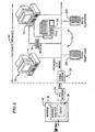
- Fig. 2 depicts such an integrated environment.
- a connection point in the home to the telephony world e. g.. the world of video, voice, high speed data network traffic
- cable modem 30 which would include an HPNA transceiver.
- the cable modem system provider may also wish to accommodate providing telephone service along with high speed data service.
- a home computer user rather than using a traditional modem to connect to an internet service provider, would find it convenient to utilize cable modem 30, taking advantage of the very high speed data service provided by the cable modem. Having a cable modem customer, the cable modem provider may also find it commercially beneficial to offer video feeds, and telephone service over the same cable modem network.
- Cable modem 30 would be coupled to Headend 32 over Hybrid Fiber Coaxial (HFC) network 34.
- Headend 32 would include internet router 36 having Cable Modem Termination System (CMTS) 38 for communication with the Internet.
- CMTS Cable Modem Termination System
- a CM/CMTS system can be implemented using the Broadcom Corporation Model Number BCM3210 Cable Modem Termination System product and is described in detail in U.S. Patent 6,763,032 entitled "Cable Modem System with Sample and Packet Synchronization".
- Telephone handset 40 is connected to terminal 42 which consists in partof: (a) voice codec 44, which converts between analog signals and sampled digital signals at a sample rate which is determined by a clock in the codec (hereinafter"Clock 2"), and (b) HPNA network interface (I/F) 46a, which assembles the voice samples into a packet (e.g., such as a layer-2 frame type) which is then transmitted on HPNA network 48 to gateway 50.
- voice codec 44 which converts between analog signals and sampled digital signals at a sample rate which is determined by a clock in the codec (hereinafter"Clock 2")
- HPNA network interface (I/F) 46a which assembles the voice samples into a packet (e.g., such as a layer-2 frame type) which is then transmitted on HPNA network 48 to gateway 50.
- Gateway 50 receives the HPNA packet at counterpart HPNA networkl/F 46b and queues it for transmission by Wide Area Network (WAN) interface 52. This transmission is made synchronous to a gateway clock (hereinafter"Clock 1") in gateway 50 which is determined by the access equipment at the other end of the DOCSISlink 56, e.g. the CMTS, should gateway 50 be part of cable modem 30 as seen in Fig. 2. Clock 1 is made synchronous in gateway 50 in accordance with the teachings of U.S. Patent 6,763,032 referenced above.
- the packet sent up WAN DOCSIS link 56 is routed across global Internet Protocol (IP) network 54 to the destination e.g. a comparable gateway/terminal combination (or equivalent) to that of gateway 50 combined with terminal 42.
- IP Internet Protocol
- voice packets received over the DOCSIS WAN link 56 by WANI/F 52 are transmitted by gateway HPNAI/F 46b over HPNA network 48 to terminal HPNAI/F 46a, where the packet is disassembled back into samples which are converted by voice codec 44 back into analog signals for telephone handset 40.
- Fig.3 is a depiction of information transition 60 from the DOCSIS domain (synchronous to Clock 1) to the asynchronous HPNA network (which introduces some jitter), and transition 62 from the asynchronous HPNA network to the terminal voice codec domain (synchronous to Clock 2).
- the present invention provides a solution to such need.
- a method is providing for synchronizing one or more synchronous terminals with one or more synchronous endpoints, each synchronous terminal and each synchronous endpoint having an asynchronous communications network coupled between at least one synchronous terminal and at least one synchronous endpoint.
- a synchronization protocol (SP) is established between a synchronous terminal and a synchronous end point by providing a gateway between the asynchronous communications network and the synchronous end point, the gateway communicating with the synchronous terminal over the asynchronous communications network in accordance with the synchronization protocol.
- the synchronization protocol includes sending a message (referred to herein as an "SP packet") from the gateway to the synchronous terminal, the SP packet containing a timestamp identifying a clock associated with the synchronous end point.
- the synchronous terminal establishes a clock associated with the synchronous terminal by creating a clock estimate based upon the timestamp message and measurements of the access jitter introduced by the asynchronous communications network such that the clock associated with the synchronous terminal enables packet sampling and transmission onto the asynchronous communications network to and from the synchronous terminal to be synchronized with the clock associated with the synchronous end point.
- a telephony device (hereinafter “Terminal”) is attached to a packet network, such as Ethernet or HPNA.
- the Terminal samples the voice signal at a synchronous rate (e.g. 8 kHz samples), and collects some number of samples (e.g. 80 samples or 10 milliseconds) into a single packet.
- the voice samples in the packet are compressed, using one ofseveral well-known voice compression algorithms. (However, it should be noted that such compression is independent of the invention described herein.)
- the Terminal When a voice packet is assembled, the Terminal attempts to send the packet over the HPNA segment to a gateway device (hereinafter "Gateway"), e.g., a cable modem, which then forwards the packet over a wide-area link which is providing the packetized voice service.
- a gateway device hereinafter "Gateway"
- the link between the Gateway and the global network may be synchronous (e.g. providing periodic slots for packet transmission every 10ms).
- HPNA is a class of Ethernet network, where access to the network is determined by a Carrier Sense Multiple Access (CSMA) technique.
- CSMA Carrier Sense Multiple Access
- the latency introduced by network access includes an exponentially distributed delay resulting from the Collision Resolution process of the CSMA network. Further delay is created by the presence of other active stations on the network which gain access to the network prior to Terminal's packet transmission. These delays count against a limited overall network latency budget, such access delays contributing to the reduction in network voice quality.
- worst case delays must be concatenated if there is not synchronization between the delay mechanisms. If synchronization can be achieved, then worst case delays can be aligned such that the overall delay is reduced to the single maximum delay encountered.
- Fig. 4a shows that when Clock 1 and Clock 2 are not at the same frequency then "timing slips" 70 can occur where the periodic transfer of packets from Clock 2 to Clock 1 are interrupted because either: (a) Clock 1 has drifted in phase to the point where two packets arrive in the same Clock I interval, or (b) no packet arrives in a Clock I interval (not shown).
- Fig. 4b shows what happens when timing jitter 72 is introduced in the transmission from Terminal to Gateway by access delays on the HPNA network. Assuming the jitter is less than a given Clock 1 interval (e.g.. 10 milliseconds), then certain phase offsets between Clock 1 and Clock 2 are safe as depicted at timing 74 in Fig. 4b.
- a given Clock 1 interval e.g. 10 milliseconds
- the source of possible HPNA jitter is how discussed.
- the HPNA network introduces a variable amount of delay, between the time an I/F has a packet ready to transmit (at T0), and the time when that packet actually commences transmission on the wire.
- This delay can be contributed by several factors: (a) the delay from T0 to when the currently active station (if any) finishes its transmission - this can amount to over 3 milliseconds on an HPNA network (hereinafter referred to as "Basic Access Delay”); (b) additional delay introduced by stations transmitting at a higher priority (PRI), which are always granted access before stations of lower priority, but since it assumed that packetized voice traffic uses the highest priority, this delay, in effect, does not exist: (c) delay needed to resolve collisions with other stations attempting to transmit on this high priority, e.g. other packetized voice stations (hereinafter referred to as "CRA Delay”), and (d) delay caused by those other stations winning the collision resolution and therefore transmitting before this station (hereinafter referred to as "
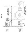
- Fig. 5 shows an example depicting a Best Case scenario and a Delay Case scenario.
- Voice Packet 3 (for example, where there are three packetized voice stations sending packets) is transmitted at T0.
- Delay Case scenario there are potential delays caused by previous packet transmission 80.
- Voice Packet 2 and Voice Packet 3. and Priority Access Delay for transmissions from packetized voice stations sending Voice Packet 1 and Voice Packet 2.
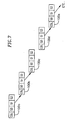
- Fig. 6 shows an example of how collision resolution results in access delay in HPNA networks.
- the media access method of HPNA is described in detail in commonly assigned pending U.S. Patent Application No. 09/026,884 entitled "Packet-Switched Multiple-Access Network System with Distributed Fair Priority Queuing".
- CSMA/CD carrier sense multiple access with collision detection
- stations detect a collision they cease transmission and each station chooses a position in a 3-way ordering, and indicates its choice by sending a Signal (shown as S0, S1, S2 in Fig. 6).
- Fig. 7 shows Cumulative Distribution percentage as a function ofDelay under increasing offered load for both tightly bounded latency and unbounded latency situations.
- Fig. 8 the statistics are shown for a large number of transmissions attempts by a station on an HPNA network using DFPQ collision resolution.
- the horizontal axis indicates a time (or latency) taken to resolve collisions and gain access to the channel.
- the vertical axis indicates the percentage of transmission attempts that involve delay less than or equal to the corresponding position on the horizontal axis. This is commonly referred to as a cumulative distribution.
- Fig. 8 There are several curves shown in Fig. 8. each corresponding to an increasing amount of offered load on the network, up to 100% of achievable throughput. Naturally, the higher offered loads correspond to those curves that reach a given level of cumulative distribution further to the right (increased delay) on the diagram. For instance, the rightmost curve of Fig. 8 indicates that 90% of transmission attempts see a delay of less than 16 Frame Times (where Frame Time is an arbitrary measurement of delay referred to the time taken to transmit a nominal packet of 512 bytes).
- Fig. 8 What is significant in the comparison of Fig. 8 versus Fig. 9 is that the important characteristic is the bound on latency that is only exceeded a small fraction of the time. i.e.. the point where the curve approaches the 100% limit within all but for a negligible number of events. This point occurs at a much larger delay for Fig. 9 (Ethernet BEB) than Fig. 8 (HPNA DFPQ).
- the system requirement for acceptable voice transmission may state that the delay bound can only be exceeded in one out of a million events.
- a solution is to synchronize the phone codec with the Gateway synchronous transport (DOCSIS 10ms or ADSL cell slot time) by means of a Link Layer protocol. i.e.. Synchronization Protocol (SP) between the Gateway and the codec.
- SP Synchronization Protocol
- the codec creates a packetized sample (nominally every 10 ms) synchronous with, and advanced by a fixed window, from the upstream slot of the Gateway.
- the amount of advanced window is just enough for the maximum jitter on the HPNA network (4+ ms), so that in the worst case the codec sample arrives at the Gateway just in time.
- the parallel construct deals with downstream voice).
- Packetized voice traffic is transmitted over HPNA using a priority mechanism (a 3-bit priority number associated with each station's transmission) which allows packetized voice traffic to gain access in preference to lower priority traffic such as data traffic, or non-real-time streaming media traffic.
- a priority mechanism a 3-bit priority number associated with each station's transmission
- PRI Priority
- the only latency seen by voice traffic is then the delay (Basic Access Delay) as a result of a previous (possibly lower priority) transmission finishing on the wire (e.g. a maximum of 4 ms), plus the delay caused by other packetized voice transmissions.
- a collision resolution cycle resolves in exponential time, but with a maximum delay (CRA Delay) at some low drop rate (10 -6 packets).
- CRA Delay maximum delay
- a synchronous basis e.g. DOCSIS
- the latency described herein is the delay measured from the last voice sample in a packet, but the first sample of the packet is always further delayed by the time taken to assemble the multiple samples into a packet for transmission, called the "packetization delay".
- packetization delay typically voice is sampled at an 8 kiloHertz rate and 80 samples are assembled into a packet, resulting in a packetization delay of 10ms.
- Additional parts of the invention can reduce the CRA Delay, Priority Access Delay and Basic Access Delay.
- the SP can be extended to specify the detailed ordering between Terminals.
- Each Terminal observes transmissions on the wire, and initiates its transmission after it has seen the transmission from the Terminal which immediately precedes it in the broadcast ordering. In this way there are no collisions between Terminal transmissions and no CRA Delay.
- the Priority Access Delay is now known to each station, and that delay time can be used to overlap other delay processes such as voice compression.
- non- packetized voice terminals e.g., network clients 14 shown in Fig. 1. can observe the same SP and establish a "keep out window” (KOW), such that their lower priority transmissions are deferred if the station notices that transmitting would result in the transmission overlapping the high priority packetized voice traffic.
- KW keep out window
- the observance of the KOW can be made sensitive to the network loading, so that the bandwidth lost to the keep-out interval does not impact total network throughput. For example, when network loading is light the KOW is observed, but when the network offered load is at a maximum for some averaging time, the KOW could be sacrificed for highest throughput. This might be acceptable, as the latency improvement would be achieved in most cases. Without this mechanism the Basic Access Delay would be seen even when the network loading was modest.
- An alternative method for ordering is to use the standard collision resolution mechanism once to determine an order, but then, on subsequent access to the network each terminal remembers the ordering that resulted and sequences its transmissions with other stations to replicate that ordering, without further collisions or collision resolution cycles.
- BL Backoff Level
- the Basic Access Delay (up to 4 ms) can be eliminated by a MAC keep-out (KOW) which is respected by all the lower priority stations.
- KOW MAC keep-out
- an alternative technique where there are HPNA stations that do not know about KOW is for the first-ordered packetized voice station to start it's CSMA access 4 ms ahead of the nominal synchronization time, and when it actually gains access to the wire (anywhere from 4 to 0 ms before synchronization time), it transmits a frame which is just long enough to extend to the synchronization time.
- the frame commences with null data or padding to fill out the frame (a PAD) to reach the synchronization time, and then has the voice sample packet at the very end and the rest of the frame.
- the active packetized voice stations ensure there is no Basic Access Delay, since the end of the first voice packet occurs at a predictable time.
- the cost is that no lower-priority station can commence transmission during 40% of the 10 ms periods on the wire, potentially reducing maximum data throughput by some amount, perhaps 20% on the average depending on frame sizes.
- Similar loss of performance occurs with either a cooperative keep-out mechanism, or a busy-keep-out method, although the cooperative method does allow traffic in the 4 ms prior to synchronization that is guaranteed to finish before synchronization. Perhaps this reduces the average throughput loss to less than 20%.
- a busy-keep-out mechanism can be selectively used by packetized voice stations depending on some policy decisions. For instance, it might be acceptable to have absolute best latency when the HPNA network isn't very busy, but then degrade softly to a little more jitter and voice quality impact if the offered load is high. Or, this could be a mode that is dependent on configuration parameters that can be controlled by the packetized voice service provider.
- the keep-out time could be adjusted to less than 4 ms if it was known that the maximum transmission time for lower-priority frames was limited, either because high bits-per-baud rates were used, or if the Maximum Transmission Unity (MTU) was limited (e.g., to 576 bytes). In this case the loss of maximum aggregate network rate could be reduced.
- MTU Maximum Transmission Unity
- the packetized voice station could adaptively discover the MTU size being used by flows active on the network, and reduce the keep-out time to just what is needed for the actual frame sized, to allow maximum efficiency. If some new stations start transmitting longer frames, the packetized voice stations could react by increasing the keep-out time as necessary. There might not even be a slip in many cases, as the packetized voice station can observe the traffic preceding the KOW, and notice the presence of longer frames requiring longer keep-out. The algorithm could devolve to tracking the peak frame length seen on the wire, and using a keep-out period just a litter longer.
- the keep-out delay only has to be as long as the maximum frame size (either maximum possible or peak seen recently) less the jitter amount.
- packetized voice codecs can be synchronized to the upstream synchronous segment of the network such that the phase of the codec packetization can be controlled allowing the sample packet to be ready just before the DOCSIS upstream grant.
- the HPNA MAC can be arranged so that the packetized voice stations get access to the wire at a deterministic time, and as a result the delay from codec to DOCSIS upstream can be constrained to less than 1ms.
- FIG. 10 there is now shown an illustration of the operation of the SP over the network previously described above in conjunction with Fig. 3.
- Clock 1 is derived from the DOCSIS access link, assumed here to occur with a nominal period of 10 milliseconds.
- This clock is recovered in the DOCSIS WAN I/F in the Gateway. This clock is used to initiate an SP packet transmission on HPNA network 48 (broadcast to all the Terminals). This packet contains timestamp 200 derived from Clock 1.
- This packet is delayed by a variable amount of time, determined by the access mechanism of the HPNA network, resulting in "access jitter" 202 in the timing of when the packet is sent from HPNA I/F 1 46b and arrives at HPNA I/F 2 46a. (It is assumed that the transmission delay once I/F 1 has obtained access to the network is nominal and can be compensated for in the algorithm.)
- HPNA I/F 2 46a in Terminal 42 measures the time of arrival of the SP packet, and passes that time and the packet to Time Synchronization module 204, which computes estimate 206 of when Clock 1 should next occur. This time is used to control Clock 2. with offset 208 introduced as necessary to achieve sufficient margin in system operation.
- timestamp 200 is introduced in the SP packet at the time the packet is sent on HPNA network 48. after access to the network has been achieved. Thus, timestamp 200 reflects accurately the phase of Clock 1 and can be used to control Clock 2.
- timestamp 200 is introduced in the SP packet when the packet is queued for transmission by HPNA I/F 1 46b. which measures the access delay error encountered by that packet. This error information is sent in a subsequent SP packet such that Time Synchronization module 204 can compensate for the timing error.
- the estimated phase of Clock 1 is a series of samples which can be filtered to reduce the noise in the phase estimate.
- the filter is determined by standard sampled system theory based on the characteristics of the timing channel. For instance, a simple low pass filter will reduce the short-term jitter of the resulting estimate.
- Fig. 11 illustrates the method of the second embodiment which includes a mechanism in a Terminal device, which adjusts the phase of Clock 2 206 to a known position relative to Clock 1. which is source from the Gateway. Not shown in this figure is a control loop which adjusts the frequency of Clock 2 to correspond to Clock 1. but this can be accomplished by several well-known methods.
- Clock 2 is represented by a 32-bit counter which increments at a rate sufficient to obtain desired phase resolution.
- the value of the Clock 2 counter is sampled and stored 220 in a data record 222 along with synchronization information from the SP packet.
- This synchronization information includes C1 timestamp 222 along with offset error 226 measured by the Gateway on the transmission of the previous SP packet.
- the difference between the sampled Clock 2 and Clock 1 timestamps is calculated 228 and stored in register Z 230.
- the previous SP offset is subtracted 232 from the value stored in register Z 230 from the previous packet. This produces an instantaneous measurement of phase error between Clock 1 and Clock 2.
- This value is then filtered 234 (for example, average over several intervals) and is added 236 to Clock 2 to produce a phase corrected Clock 2.
- Fig. 12 another aspect of the present invention is described.
- all stations that are ready to commence transmission at the time of the first collision participate in the collision resolution cycle - other stations arriving later defer until ALL contending stations resolve and transmit. Therefore, in accordance with the present invention delay caused by collision resolution (CRA Delay) is minimized by ensuring that all packetized voice stations attempt to transmit at the same time so that they will contend in only one collision resolution cycle.
- CRA Delay collision resolution
- the Clock synchronization of the Terminals is adjusted such that all Terminals become ready to transmit their packet (upstream) at T0. which is just after transmission commences from the Gateway (downstream) to the Terminals.
- Fig. 12 it should be noted that the Gateway transmission start can be offset from the DOCSIS upstream transmission window so that the Terminal transmissions will be received before the DOCSIS upstream transmission window commences.
- the methods involve ordering information sent from the Gateway to each Terminal, specifying the order among the terminals. This ordering substitutes for the ordering that would otherwise be established using collisions.
- the Terminals are told their position in the transmission ordering, and the Terminal waits until it has seen the prior ordered transmissions complete before attempting transmission.
- a variant of this method has each Terminal watch for the MAC address of the Terminal preceding it in transmission order.
- the Terminals are told what "BACKOFF LEVEL" they should initially use for MAC access, which is a parameter normally derived during a collision resolution cycle using the DFPQ algorithm.
- the Gateway essentially pre-computes the result of collision resolution, and communicates that to the terminals. Then the Terminals access the medium without collisions, avoiding the CRA Delay.
- a third method for eliminating CRA Delay involves Terminals initially using the standard collision resolution method, but on subsequent transmission re-using the transmission ordering obtained without repeating the collision resolution.
- the timing of the Terminal transmission becomes very predictable, allowing the terminals to minimize the delay between the sampling of the voice signal and the packet transmission on the HPNA network. Without this predictability more buffering would be needed at some point in the transmission path, which increases the average and maximum delay in the network path.
- a KOW 600 which defers lower-priority (non- packetized voice) transmission from occurring at a time that would cause Basic Access Delay to the Gateway transmission.
- the KOW is established at a point such that the longest legal packet can be transmitted and finished before the scheduled time for the Gateway downstream transmission.
- the KOW is defined as that needed to ensure that the specific transmission from the lower priority station can complete before the Gateway scheduled time, this determination being made by the station using an estimate of the transmission time for the next packet.
- the transmission time is variable because the variable length nature of packets and the adaptive modulation rate used by HPNA networks.
- the KOW is suppressed if the network loading exceeds a pre-determined threshold.
- BKOW bus-keep-out
- the packet format in this case consists of a string of PAD values which precede the actual packet contents. Terminals strip off this PAD sequence when receiving the Gateway packet, resulting in the actual packet transmitted at the right time. Note that the BKOW mechanism can be dynamically adjusted by the Gateway to enforce specific performance as needed.
- the KOW window can be reduced if all stations cooperatively avoid transmissions longer than a maximum amount, whether because the adaptive modulation achieved short transmission times, or Maximum Transmission Unit (MTU) size was limited by configuration or packet fragmentation.
- the KOW window can be dynamically sized by estimating the maximum packet transmission length by observations of traffic on the network. The KOW can be reduced if some jitter is allowable, up to some maximum.
Abstract
Description
Termination System (CMTS) 38 for communication with the Internet. A CM/CMTS system can be implemented using the Broadcom Corporation Model Number BCM3210 Cable Modem
Termination System product and is described in detail in U.S. Patent 6,763,032 entitled "Cable Modem System with Sample and Packet Synchronization".
Claims (10)
- A method of synchronizing one or more synchronous terminals (42) with one or more synchronous endpoints,
each synchronous terminal (42) and each synchronous endpoint having an asynchronous communications network (48) coupled between at least one synchronous terminal (42) and at least one synchronous endpoint,
wherein a synchronization protocol is established between a synchronous terminal (42) and a synchronous end point and wherein the synchronization protocol includes sending a message containing a timestamp (200),
characterized by:wherein the synchronization protocol includes the message from the gateway (50) to the synchronous terminal (42), the message containing the timestamp (200) identifying a clock (1) associated with the synchronous end point;establishing said synchronization protocol between a synchronous terminal (42) and a synchronous end point by providing a gateway (50) between the asynchronous communication network (48) and the synchronous end point, the gateway (50) communicating with the synchronous terminal (42) over the asynchronous communications network (48) in accordance with the synchronization protocol;
wherein the synchronous terminal (42) establishes a clock (2) associated with the synchronous terminal (52) by creating a clock estimate (206) based upon the timestamp message and access jitter (202) expected from the asynchronous communication network (48) such that the clock (2) associated with the synchronous terminal (42) enables packet sampling and transmission onto the asynchronous communication network (48) to and from the synchronous terminal (42) to be synchronized with the clock (1) associated with the synchronous end point. - The method of Claim 1, wherein an attempted transmission by each terminal (42) over the asynchronous communications network (48) is ordered such that each synchronous terminal (42) attempts to transmit at the same time after the message is sent from the gateway (50).
- The method of Claim 2, wherein each synchronous terminal (42) retains ordering information from collision resolution cycles and the ordering information is used repeatedly for further transmissions in place of collision resolution.
- The method of Claim 1, wherein the synchronization protocol includes establishing keep-out windows for terminals (42) coupled to the asynchronous communications network (48) having a terminal access priority lower than an access priority for the one or more synchronous terminals (42), the keep-out windows preventing the terminals (42) coupled to the asynchronous communications network (48) having a terminal access priority lower than an access priority for the one or more synchronous terminals (42) from transmitting on the asynchronous communications network (48) before the completion of sending a message from the gateway (50) to the synchronous terminal (42).
- The method of Claim1, wherein the access jitter (202) includes one or more of : basic access delay, collision resolution delay, or priority access delay.
- A communications network for synchronizing one or more synchronous terminals (42) with one or more synchronous endpoints, each synchronous terminal (42) and each synchronous endpoint having an asynchronous communications network (48) coupled between at least one synchronous terminal (42) and at least one synchronous endpoint, and a synchronization protocol established between a synchronous terminal (42) and a synchronous end point wherein the synchronization protocol is arranged to include sending a message containing a timestamp (200), the communications network
characterized in that:wherein the synchronization protocol is arranged to include the message from the gateway (50) to the synchronous terminal (42), the message containing the timestamp (200) identifying a clock (1) associated with the synchronous end point;a gateway (50) is provided between the asynchronous communication network (48) and the synchronous end point, the gateway being arranged for communicating with the synchronous terminal (42) over the asynchronous communications network (48) in accordance with the synchronization protocol;
wherein the synchronous terminal (42) is arranged to establish a clock (2) associated with the synchronous terminal (52) by creating a clock estimate (206) based upon the timestamp message and access jitter (202) expected from the asynchronous communication network (48) such that the clock (2) associated with the synchronous terminal (42) is arranged to enable packet sampling and transmission onto the asynchronous communication network (48) to and from the synchronous terminal (42) to be synchronized with the clock (1) associated with the synchronous end point. - The communications network of Claim 6, wherein an attempted transmission by each terminal (42) over the asynchronous communications network (48) is ordered such that each synchronous terminal (42) is arranged to attempt to transmit at the same time after the message is sent from the gateway (50).
- The communications network of Claim 7, wherein each synchronous terminal (42) is arranged to retain ordering information from collision resolution cycles and the ordering information is used repeatedly for further transmissions in place of collision resolution.
- The communications network of Claim 6, wherein the synchronization protocol is arranged to include establishing keepout windows for terminals (42) coupled to the asynchronous communications network (48) having a terminal access priority lower than an access priority for the one or more synchronous terminals (42), the keep-out windows arranged for preventing the terminals (42) coupled to the asynchronous communications network (48) having a terminal access priority lower than an access priority for the one or more synchronous terminals (42) from transmitting on the asynchronous communications network (48) before the completion of sending a message from the gateway (50) to the synchronous terminal (42).
- The communications network of Claim 6, wherein the access jitter (202) includes one or more of : basic access delay, collision resolution delay, or priority access delay.
Applications Claiming Priority (3)
| Application Number | Priority Date | Filing Date | Title |
|---|---|---|---|
| US16982499P | 1999-12-08 | 1999-12-08 | |
| US169824P | 1999-12-08 | ||
| PCT/US2000/033172 WO2001043325A1 (en) | 1999-12-08 | 2000-12-07 | Synchronized transport across non-synchronous networks |
Publications (2)
| Publication Number | Publication Date |
|---|---|
| EP1236295A1 EP1236295A1 (en) | 2002-09-04 |
| EP1236295B1 true EP1236295B1 (en) | 2005-08-17 |
Family
ID=22617326
Family Applications (1)
| Application Number | Title | Priority Date | Filing Date |
|---|---|---|---|
| EP00983999A Expired - Lifetime EP1236295B1 (en) | 1999-12-08 | 2000-12-07 | Synchronized transport across non-synchronous networks |
Country Status (6)
| Country | Link |
|---|---|
| US (2) | US6747996B2 (en) |
| EP (1) | EP1236295B1 (en) |
| AT (1) | ATE302511T1 (en) |
| AU (1) | AU2068201A (en) |
| DE (1) | DE60022082T2 (en) |
| WO (1) | WO2001043325A1 (en) |
Families Citing this family (78)
| Publication number | Priority date | Publication date | Assignee | Title |
|---|---|---|---|---|
| US6480510B1 (en) | 1998-07-28 | 2002-11-12 | Serconet Ltd. | Local area network of serial intelligent cells |
| US6956826B1 (en) | 1999-07-07 | 2005-10-18 | Serconet Ltd. | Local area network for distributing data communication, sensing and control signals |
| US6690677B1 (en) | 1999-07-20 | 2004-02-10 | Serconet Ltd. | Network for telephony and data communication |
| AU2068201A (en) * | 1999-12-08 | 2001-06-18 | Broadcom Homenetworking, Inc. | Synchronized transport across non-synchronous networks |
| GB9930132D0 (en) * | 1999-12-22 | 2000-02-09 | Ericsson Telefon Ab L M | Telecommunication network synchronisation |
| US7035270B2 (en) * | 1999-12-30 | 2006-04-25 | General Instrument Corporation | Home networking gateway |
| US6549616B1 (en) | 2000-03-20 | 2003-04-15 | Serconet Ltd. | Telephone outlet for implementing a local area network over telephone lines and a local area network using such outlets |
| US6877043B2 (en) * | 2000-04-07 | 2005-04-05 | Broadcom Corporation | Method for distributing sets of collision resolution parameters in a frame-based communications network |
| IL135744A (en) | 2000-04-18 | 2008-08-07 | Mosaid Technologies Inc | Telephone communication system over a single telephone line |
| US6842459B1 (en) | 2000-04-19 | 2005-01-11 | Serconet Ltd. | Network combining wired and non-wired segments |
| US7961712B2 (en) * | 2000-05-08 | 2011-06-14 | Broadcom Corporation | System and method for supporting multiple voice channels |
| US7068725B2 (en) * | 2000-07-10 | 2006-06-27 | Garmin At, Inc. | Bit detection threshold in a TDMA burst communication system |
| WO2002009331A2 (en) * | 2000-07-20 | 2002-01-31 | Thomson Licensing S.A. | Multi-media jitter removal in an asynchronous digital home network |
| AU2001271632A1 (en) * | 2000-07-26 | 2002-02-05 | Thomson Licensing S.A. | Multi-media jitter removal in an asynchronous digital home network |
| US6977919B1 (en) | 2000-07-31 | 2005-12-20 | Harington Valve Llc | Method and apparatus for efficient bandwidth utilization in subscriber unit initialization and synchronization in a time-synchronized communication system |
| US20020062415A1 (en) * | 2000-09-29 | 2002-05-23 | Zarlink Semiconductor N.V. Inc. | Slotted memory access method |
| US7023883B1 (en) * | 2000-12-27 | 2006-04-04 | Cisco Technology, Inc. | Method for providing a network timing reference clock in ethernet-connected VOIP equipment |
| US7293103B1 (en) | 2001-02-20 | 2007-11-06 | At&T Corporation | Enhanced channel access mechanisms for a HPNA network |
| WO2002069536A1 (en) * | 2001-02-28 | 2002-09-06 | Symmetricom, Inc. | Measurement of time-delay, time-delay-variation, and cell transfer rate in atm networks |
| US20020194343A1 (en) * | 2001-02-28 | 2002-12-19 | Kishan Shenoi | Measurement of time-delay, time-delay-variation, and cell transfer rate in ATM networks |
| US7512158B2 (en) * | 2001-03-21 | 2009-03-31 | Thomson Licensing | Jitter prevention in a digital communication network |
| US7191354B2 (en) * | 2001-03-29 | 2007-03-13 | Nokia Corporation | Method for synchronizing a first clock to a second clock, processing unit and synchronization system |
| CA2344743C (en) * | 2001-04-20 | 2011-12-06 | Elysium Broadband Inc. | Point to multi-point communications system |
| US7133423B1 (en) * | 2001-06-19 | 2006-11-07 | Advanced Micro Devices, Inc. | Maintaining synchronization between frame control word and data frame pairs in a home network |
| IL144158A (en) | 2001-07-05 | 2011-06-30 | Mosaid Technologies Inc | Outlet for connecting an analog telephone set to a digital data network carrying voice signals in digital form |
| GB0129386D0 (en) | 2001-12-07 | 2002-01-30 | Nokia Corp | Transmission timing |
| US6783456B2 (en) | 2001-12-19 | 2004-08-31 | Scientific Games Royalty Corporation | Methods and systems for conducting lottery-type games with strategy elements |
| US7545819B1 (en) | 2002-02-15 | 2009-06-09 | Network Equipment Technologies, Inc. | Techniques for asynchronous compensation for secure communications |
| US7640485B1 (en) * | 2002-02-15 | 2009-12-29 | Network Equipment Technologies, Inc. | Non-relay initialization for modems |
| US6775300B2 (en) | 2002-02-28 | 2004-08-10 | Teknovus, Inc. | Clock distribution in a communications network |
| US7088677B1 (en) * | 2002-03-01 | 2006-08-08 | Bellsouth Intellectual Property Corporation | System and method for delay-based congestion detection and connection admission control |
| US7724764B2 (en) * | 2002-04-23 | 2010-05-25 | Coppergate Communications Ltd. | Adaptive synchronous media access protocol for shared media networks |
| EP1520380B1 (en) * | 2002-07-10 | 2005-12-07 | Telefonaktiebolaget LM Ericsson (publ) | Synchronous data transfer system for time-sensitive data in packet-switched networks |
| US6999433B2 (en) * | 2002-10-17 | 2006-02-14 | Coppergate Communication Ltd. | Method of reducing near-end crosstalk in an MxU networking architecture |
| US7693189B2 (en) * | 2002-10-17 | 2010-04-06 | Coppergate Communication Ltd. | HPNA hub |
| US20040078828A1 (en) * | 2002-10-18 | 2004-04-22 | Parchman Travis Randall | Recovering timing for television services |
| IL152824A (en) | 2002-11-13 | 2012-05-31 | Mosaid Technologies Inc | Addressable outlet and a network using same |
| JP3993508B2 (en) | 2002-12-02 | 2007-10-17 | 株式会社エヌ・ティ・ティ・ドコモ | Wireless access network system, wireless communication method, synchronization server, and node device |
| US7346071B2 (en) | 2003-01-13 | 2008-03-18 | Bareis Bernard F | Broadband multi-drop local network, interface and method for multimedia access |
| IL154234A (en) | 2003-01-30 | 2010-12-30 | Mosaid Technologies Inc | Method and system for providing dc power on local telephone lines |
| IL154921A (en) | 2003-03-13 | 2011-02-28 | Mosaid Technologies Inc | Telephone system having multiple distinct sources and accessories therefor |
| IL157787A (en) | 2003-09-07 | 2010-12-30 | Mosaid Technologies Inc | Modular outlet for data communications network |
| US7525984B2 (en) * | 2003-07-23 | 2009-04-28 | Mediatek Inc. | Method and apparatus for unifying MAC protocols |
| WO2005022805A2 (en) * | 2003-09-01 | 2005-03-10 | Shimon Ben-David | Distributed multimedia and messaging router over layer 2 |
| US7364091B2 (en) | 2003-12-19 | 2008-04-29 | Scientific Games International, Inc. | Embedded optical signatures in documents |
| IL159838A0 (en) | 2004-01-13 | 2004-06-20 | Yehuda Binder | Information device |
| IL160417A (en) | 2004-02-16 | 2011-04-28 | Mosaid Technologies Inc | Outlet add-on module |
| US8149880B1 (en) | 2004-08-18 | 2012-04-03 | Qualcomm Atheros, Inc. | Media streaming synchronization |
| US7792158B1 (en) | 2004-08-18 | 2010-09-07 | Atheros Communications, Inc. | Media streaming synchronization |
| KR20070084102A (en) | 2004-10-28 | 2007-08-24 | 사이언티픽 게임스 인터내셔널, 아이엔씨. | Lottery game played on a geometric figure using indicia with variable point values |
| US7408949B2 (en) * | 2004-12-01 | 2008-08-05 | Coppergate Communications Ltd. | Hybrid telephone, non-telephone network |
| US7662038B2 (en) | 2005-01-07 | 2010-02-16 | Scientific Games International, Inc. | Multi-matrix lottery |
| JP2008526374A (en) | 2005-01-07 | 2008-07-24 | サイエンティフィック ゲイムズ インターナショナル インコーポレイテッド | Lottery game using nostalgic game theme |
| US7824257B2 (en) | 2005-01-11 | 2010-11-02 | Scientific Games International, Inc. | On-line lottery game in which supplemental lottery-selected indicia are available for purchase |
| US8262453B2 (en) | 2005-02-09 | 2012-09-11 | Scientific Games International, Inc. | Combination lottery and raffle game |
| US7874902B2 (en) | 2005-03-23 | 2011-01-25 | Scientific Games International. Inc. | Computer-implemented simulated card game |
| EP1874418A1 (en) | 2005-04-27 | 2008-01-09 | Scientific Games International, Inc. | Game apparatus |
| US7654529B2 (en) | 2005-05-17 | 2010-02-02 | Scientific Games International, Inc. | Combination scratch ticket and on-line game ticket |
| US7742505B2 (en) * | 2005-12-14 | 2010-06-22 | Adtran, Inc. | Systems and methods for enabling clock signal synchronization |
| US7539889B2 (en) | 2005-12-30 | 2009-05-26 | Avega Systems Pty Ltd | Media data synchronization in a wireless network |
| US8462627B2 (en) * | 2005-12-30 | 2013-06-11 | Altec Lansing Australia Pty Ltd | Media data transfer in a network environment |
| US7821876B2 (en) * | 2006-02-27 | 2010-10-26 | Frantz Frederick E | Synchronization of a plurality of devices in a wireless sensor arrangement |
| IL176288A0 (en) * | 2006-06-13 | 2007-07-04 | Imagine Comm Ltd | Synchronous transmission over packet based network |
| US7949039B2 (en) * | 2006-06-19 | 2011-05-24 | Acterna Llc | Home network testing |
| US7733999B2 (en) * | 2006-06-20 | 2010-06-08 | Ciena Corporation | System and method for an adaptable timing recovery architecture for critically-timed transport applications |
| WO2008024818A2 (en) * | 2006-08-22 | 2008-02-28 | Brilliant Telecommunications, Inc. | Apparatus and method of controlled delay packet forwarding |
| JP2008118548A (en) * | 2006-11-07 | 2008-05-22 | Sharp Corp | Communication device, and program for operating computer as communication device |
| CA2673208C (en) * | 2007-01-15 | 2014-03-11 | Research In Motion Limited | Fragmenting large packets in the presence of high priority packets |
| US8442074B1 (en) | 2007-04-02 | 2013-05-14 | Adtran, Inc. | Systems and methods for passing timing information over packet networks |
| FR2915338A1 (en) * | 2007-04-17 | 2008-10-24 | Canon Kk | METHOD FOR TRANSMITTING AND RECEIVING DATA CONTENTS IN A COMMUNICATION NETWORK, COMPUTER PROGRAM PRODUCT, STORAGE MEDIUM AND DEVICES THEREOF |
| US8401007B2 (en) * | 2009-04-06 | 2013-03-19 | Avaya Inc. | Network synchronization over IP networks |
| US8031747B2 (en) | 2009-04-29 | 2011-10-04 | Juniper Networks, Inc. | Apparatus and method of compensating for clock frequency and phase variations by processing packet delay values |
| US8135866B2 (en) * | 2010-01-22 | 2012-03-13 | Research In Motion Limited | System and method for detecting and processing stale messages |
| US8808080B2 (en) | 2010-05-14 | 2014-08-19 | Scientific Games International, Inc. | Grid-based lottery game and associated method |
| US8460081B2 (en) | 2010-05-14 | 2013-06-11 | Scientific Games International, Inc. | Grid-based multi-lottery game and associated method |
| US8554951B2 (en) * | 2011-03-08 | 2013-10-08 | Rackspace Us, Inc. | Synchronization and ordering of multiple accessess in a distributed system |
| KR101243434B1 (en) * | 2011-10-20 | 2013-03-13 | 성균관대학교산학협력단 | Synchronization method for fieldbus using gateway and synchronization system for fieldbus using gateway |
| US20160353437A1 (en) * | 2015-05-26 | 2016-12-01 | Futurewei Technologies, Inc. | System and Method for Reserving Unlicensed Spectrum |
Family Cites Families (12)
| Publication number | Priority date | Publication date | Assignee | Title |
|---|---|---|---|---|
| US6307868B1 (en) * | 1995-08-25 | 2001-10-23 | Terayon Communication Systems, Inc. | Apparatus and method for SCDMA digital data transmission using orthogonal codes and a head end modem with no tracking loops |
| US5742649A (en) * | 1995-12-15 | 1998-04-21 | Cisco Technology, Inc. | SRTS clock recovery system for use in a highly stressed network environment |
| US5640388A (en) * | 1995-12-21 | 1997-06-17 | Scientific-Atlanta, Inc. | Method and apparatus for removing jitter and correcting timestamps in a packet stream |
| JP2988418B2 (en) | 1997-03-12 | 1999-12-13 | 日本電気株式会社 | Clock synchronization system |
| US6173207B1 (en) | 1997-09-22 | 2001-01-09 | Agilent Technologies, Inc. | Real-time control system with non-deterministic communication |
| US6377588B1 (en) * | 1997-11-25 | 2002-04-23 | Nec Corporation | Method and apparatus for reducing jitter of a program clock reference in a transport stream of MPEG over ATM, and MPEG decoder |
| US6327274B1 (en) * | 1998-09-15 | 2001-12-04 | Nokia Telecommunications, Inc. | Method for estimating relative skew between clocks in packet networks |
| US6259677B1 (en) * | 1998-09-30 | 2001-07-10 | Cisco Technology, Inc. | Clock synchronization and dynamic jitter management for voice over IP and real-time data |
| US6661811B1 (en) * | 1999-02-12 | 2003-12-09 | Koninklijke Philips Electronics N.V. | Method of and apparatus for communicating isochronous data |
| US6501809B1 (en) * | 1999-03-19 | 2002-12-31 | Conexant Systems, Inc. | Producing smoothed clock and data signals from gapped clock and data signals |
| US6574237B1 (en) * | 1999-03-19 | 2003-06-03 | Agere Systems Inc. | Inoperable network device |
| AU2068201A (en) * | 1999-12-08 | 2001-06-18 | Broadcom Homenetworking, Inc. | Synchronized transport across non-synchronous networks |
-
2000
- 2000-12-07 AU AU20682/01A patent/AU2068201A/en not_active Abandoned
- 2000-12-07 US US09/732,213 patent/US6747996B2/en not_active Expired - Lifetime
- 2000-12-07 AT AT00983999T patent/ATE302511T1/en not_active IP Right Cessation
- 2000-12-07 DE DE60022082T patent/DE60022082T2/en not_active Expired - Lifetime
- 2000-12-07 EP EP00983999A patent/EP1236295B1/en not_active Expired - Lifetime
- 2000-12-07 WO PCT/US2000/033172 patent/WO2001043325A1/en active IP Right Grant
-
2004
- 2004-04-21 US US10/828,687 patent/US7359406B2/en not_active Expired - Lifetime
Also Published As
| Publication number | Publication date |
|---|---|
| DE60022082D1 (en) | 2005-09-22 |
| EP1236295A1 (en) | 2002-09-04 |
| US6747996B2 (en) | 2004-06-08 |
| AU2068201A (en) | 2001-06-18 |
| ATE302511T1 (en) | 2005-09-15 |
| US20010030978A1 (en) | 2001-10-18 |
| WO2001043325A1 (en) | 2001-06-14 |
| US20040196857A1 (en) | 2004-10-07 |
| US7359406B2 (en) | 2008-04-15 |
| DE60022082T2 (en) | 2006-06-29 |
Similar Documents
| Publication | Publication Date | Title |
|---|---|---|
| EP1236295B1 (en) | Synchronized transport across non-synchronous networks | |
| USRE46142E1 (en) | Modem with voice processing capability | |
| EP1432203B1 (en) | Low latency digital audio over packet switched networks by setting buffer size at receiver | |
| EP1281264B1 (en) | System and method for supporting multiple voice channels | |
| US5790538A (en) | System and method for voice Playout in an asynchronous packet network | |
| DK1344345T3 (en) | A method and apparatus for reducing the end-to-end delay in the provision of Internet telephony via a CATV cable network | |
| EP1443743B1 (en) | Using communication network statistics for jitter buffer and echo canceller control | |
| WO2001019005A1 (en) | System and method for the synchronization and distribution of telephony timing information in a cable modem network | |
| JP2004500758A (en) | Synchronization of voice packet generation and unsolicited grant in voice telephony with DOCSIS cable modem packets | |
| US20070053373A1 (en) | Packetizing media for a time slotted communication system | |
| EP1942607A2 (en) | Cable modem with voice processing capability | |
| US7542465B2 (en) | Optimization of decoder instance memory consumed by the jitter control module | |
| WO2002023824A2 (en) | Cable modem with voice processing capability | |
| US20020110152A1 (en) | Synchronizing encoder - decoder operation in a communication network | |
| Hirannaiah et al. | Influence of codecs on adaptive jitter buffer algorithm | |
| RU2369015C2 (en) | Synchronisation of vodsl for dslam, connected to ethernet only |
Legal Events
| Date | Code | Title | Description |
|---|---|---|---|
| PUAI | Public reference made under article 153(3) epc to a published international application that has entered the european phase |
Free format text: ORIGINAL CODE: 0009012 |
|
| 17P | Request for examination filed |
Effective date: 20020625 |
|
| AK | Designated contracting states |
Kind code of ref document: A1 Designated state(s): AT BE CH CY DE DK ES FI FR GB GR IE IT LI LU MC NL PT SE TR |
|
| AX | Request for extension of the european patent |
Free format text: AL;LT;LV;MK;RO;SI |
|
| RAP1 | Party data changed (applicant data changed or rights of an application transferred) |
Owner name: BROADCOM CORPORATION |
|
| 17Q | First examination report despatched |
Effective date: 20040623 |
|
| GRAP | Despatch of communication of intention to grant a patent |
Free format text: ORIGINAL CODE: EPIDOSNIGR1 |
|
| GRAS | Grant fee paid |
Free format text: ORIGINAL CODE: EPIDOSNIGR3 |
|
| GRAA | (expected) grant |
Free format text: ORIGINAL CODE: 0009210 |
|
| AK | Designated contracting states |
Kind code of ref document: B1 Designated state(s): AT BE CH CY DE DK ES FI FR GB GR IE IT LI LU MC NL PT SE TR |
|
| PG25 | Lapsed in a contracting state [announced via postgrant information from national office to epo] |
Ref country code: IT Free format text: LAPSE BECAUSE OF FAILURE TO SUBMIT A TRANSLATION OF THE DESCRIPTION OR TO PAY THE FEE WITHIN THE PRE;WARNING: LAPSES OF ITALIAN PATENTS WITH EFFECTIVE DATE BEFORE 2007 MAY HAVE OCCURRED AT ANY TIME BEFORE 2007. THE CORRECT EFFECTIVE DATE MAY BE DIFFERENT FROM THE ONE RECORDED.SCRIBED TIME-LIMIT Effective date: 20050817 Ref country code: LI Free format text: LAPSE BECAUSE OF FAILURE TO SUBMIT A TRANSLATION OF THE DESCRIPTION OR TO PAY THE FEE WITHIN THE PRESCRIBED TIME-LIMIT Effective date: 20050817 Ref country code: FI Free format text: LAPSE BECAUSE OF FAILURE TO SUBMIT A TRANSLATION OF THE DESCRIPTION OR TO PAY THE FEE WITHIN THE PRESCRIBED TIME-LIMIT Effective date: 20050817 Ref country code: ES Free format text: LAPSE BECAUSE OF FAILURE TO SUBMIT A TRANSLATION OF THE DESCRIPTION OR TO PAY THE FEE WITHIN THE PRESCRIBED TIME-LIMIT Effective date: 20050817 Ref country code: NL Free format text: LAPSE BECAUSE OF FAILURE TO SUBMIT A TRANSLATION OF THE DESCRIPTION OR TO PAY THE FEE WITHIN THE PRESCRIBED TIME-LIMIT Effective date: 20050817 Ref country code: BE Free format text: LAPSE BECAUSE OF FAILURE TO SUBMIT A TRANSLATION OF THE DESCRIPTION OR TO PAY THE FEE WITHIN THE PRESCRIBED TIME-LIMIT Effective date: 20050817 Ref country code: TR Free format text: LAPSE BECAUSE OF FAILURE TO SUBMIT A TRANSLATION OF THE DESCRIPTION OR TO PAY THE FEE WITHIN THE PRESCRIBED TIME-LIMIT Effective date: 20050817 Ref country code: CH Free format text: LAPSE BECAUSE OF FAILURE TO SUBMIT A TRANSLATION OF THE DESCRIPTION OR TO PAY THE FEE WITHIN THE PRESCRIBED TIME-LIMIT Effective date: 20050817 Ref country code: AT Free format text: LAPSE BECAUSE OF FAILURE TO SUBMIT A TRANSLATION OF THE DESCRIPTION OR TO PAY THE FEE WITHIN THE PRESCRIBED TIME-LIMIT Effective date: 20050817 |
|
| REG | Reference to a national code |
Ref country code: GB Ref legal event code: FG4D |
|
| REG | Reference to a national code |
Ref country code: CH Ref legal event code: EP |
|
| REG | Reference to a national code |
Ref country code: IE Ref legal event code: FG4D |
|
| REF | Corresponds to: |
Ref document number: 60022082 Country of ref document: DE Date of ref document: 20050922 Kind code of ref document: P |
|
| PG25 | Lapsed in a contracting state [announced via postgrant information from national office to epo] |
Ref country code: DK Free format text: LAPSE BECAUSE OF FAILURE TO SUBMIT A TRANSLATION OF THE DESCRIPTION OR TO PAY THE FEE WITHIN THE PRESCRIBED TIME-LIMIT Effective date: 20051117 Ref country code: GR Free format text: LAPSE BECAUSE OF FAILURE TO SUBMIT A TRANSLATION OF THE DESCRIPTION OR TO PAY THE FEE WITHIN THE PRESCRIBED TIME-LIMIT Effective date: 20051117 Ref country code: SE Free format text: LAPSE BECAUSE OF FAILURE TO SUBMIT A TRANSLATION OF THE DESCRIPTION OR TO PAY THE FEE WITHIN THE PRESCRIBED TIME-LIMIT Effective date: 20051117 |
|
| PG25 | Lapsed in a contracting state [announced via postgrant information from national office to epo] |
Ref country code: IE Free format text: LAPSE BECAUSE OF NON-PAYMENT OF DUE FEES Effective date: 20051207 Ref country code: CY Free format text: LAPSE BECAUSE OF FAILURE TO SUBMIT A TRANSLATION OF THE DESCRIPTION OR TO PAY THE FEE WITHIN THE PRESCRIBED TIME-LIMIT Effective date: 20051207 |
|
| PG25 | Lapsed in a contracting state [announced via postgrant information from national office to epo] |
Ref country code: MC Free format text: LAPSE BECAUSE OF NON-PAYMENT OF DUE FEES Effective date: 20051231 Ref country code: LU Free format text: LAPSE BECAUSE OF NON-PAYMENT OF DUE FEES Effective date: 20051231 |
|
| PG25 | Lapsed in a contracting state [announced via postgrant information from national office to epo] |
Ref country code: PT Free format text: LAPSE BECAUSE OF FAILURE TO SUBMIT A TRANSLATION OF THE DESCRIPTION OR TO PAY THE FEE WITHIN THE PRESCRIBED TIME-LIMIT Effective date: 20060117 |
|
| NLV1 | Nl: lapsed or annulled due to failure to fulfill the requirements of art. 29p and 29m of the patents act | ||
| REG | Reference to a national code |
Ref country code: CH Ref legal event code: PL |
|
| ET | Fr: translation filed | ||
| PLBE | No opposition filed within time limit |
Free format text: ORIGINAL CODE: 0009261 |
|
| STAA | Information on the status of an ep patent application or granted ep patent |
Free format text: STATUS: NO OPPOSITION FILED WITHIN TIME LIMIT |
|
| 26N | No opposition filed |
Effective date: 20060518 |
|
| REG | Reference to a national code |
Ref country code: IE Ref legal event code: MM4A |
|
| REG | Reference to a national code |
Ref country code: FR Ref legal event code: CA |
|
| REG | Reference to a national code |
Ref country code: FR Ref legal event code: PLFP Year of fee payment: 16 |
|
| PGFP | Annual fee paid to national office [announced via postgrant information from national office to epo] |
Ref country code: GB Payment date: 20151221 Year of fee payment: 16 |
|
| PGFP | Annual fee paid to national office [announced via postgrant information from national office to epo] |
Ref country code: FR Payment date: 20151218 Year of fee payment: 16 |
|
| REG | Reference to a national code |
Ref country code: DE Ref legal event code: R082 Ref document number: 60022082 Country of ref document: DE Representative=s name: BOSCH JEHLE PATENTANWALTSGESELLSCHAFT MBH, DE Ref country code: DE Ref legal event code: R081 Ref document number: 60022082 Country of ref document: DE Owner name: AVAGO TECHNOLOGIES INTERNATIONAL SALES PTE. LT, SG Free format text: FORMER OWNER: BROADCOM CORP., IRVINE, CALIF., US Ref country code: DE Ref legal event code: R081 Ref document number: 60022082 Country of ref document: DE Owner name: AVAGO TECHNOLOGIES GENERAL IP (SINGAPORE) PTE., SG Free format text: FORMER OWNER: BROADCOM CORP., IRVINE, CALIF., US |
|
| GBPC | Gb: european patent ceased through non-payment of renewal fee |
Effective date: 20161207 |
|
| REG | Reference to a national code |
Ref country code: FR Ref legal event code: ST Effective date: 20170831 |
|
| PG25 | Lapsed in a contracting state [announced via postgrant information from national office to epo] |
Ref country code: FR Free format text: LAPSE BECAUSE OF NON-PAYMENT OF DUE FEES Effective date: 20170102 |
|
| PG25 | Lapsed in a contracting state [announced via postgrant information from national office to epo] |
Ref country code: GB Free format text: LAPSE BECAUSE OF NON-PAYMENT OF DUE FEES Effective date: 20161207 |
|
| REG | Reference to a national code |
Ref country code: DE Ref legal event code: R082 Ref document number: 60022082 Country of ref document: DE Representative=s name: BOSCH JEHLE PATENTANWALTSGESELLSCHAFT MBH, DE Ref country code: DE Ref legal event code: R081 Ref document number: 60022082 Country of ref document: DE Owner name: AVAGO TECHNOLOGIES INTERNATIONAL SALES PTE. LT, SG Free format text: FORMER OWNER: AVAGO TECHNOLOGIES GENERAL IP (SINGAPORE) PTE. LTD., SINGAPORE, SG |
|
| PGFP | Annual fee paid to national office [announced via postgrant information from national office to epo] |
Ref country code: DE Payment date: 20191231 Year of fee payment: 20 |
|
| REG | Reference to a national code |
Ref country code: DE Ref legal event code: R071 Ref document number: 60022082 Country of ref document: DE |