EP1238871A2 - Airbag module - Google Patents
Airbag module Download PDFInfo
- Publication number
- EP1238871A2 EP1238871A2 EP02004304A EP02004304A EP1238871A2 EP 1238871 A2 EP1238871 A2 EP 1238871A2 EP 02004304 A EP02004304 A EP 02004304A EP 02004304 A EP02004304 A EP 02004304A EP 1238871 A2 EP1238871 A2 EP 1238871A2
- Authority
- EP
- European Patent Office
- Prior art keywords
- diffuser
- gas generator
- flange
- receiving housing
- airbag
- Prior art date
- Legal status (The legal status is an assumption and is not a legal conclusion. Google has not performed a legal analysis and makes no representation as to the accuracy of the status listed.)
- Withdrawn
Links
Images
Classifications
-
- B—PERFORMING OPERATIONS; TRANSPORTING
- B60—VEHICLES IN GENERAL
- B60R—VEHICLES, VEHICLE FITTINGS, OR VEHICLE PARTS, NOT OTHERWISE PROVIDED FOR
- B60R21/00—Arrangements or fittings on vehicles for protecting or preventing injuries to occupants or pedestrians in case of accidents or other traffic risks
- B60R21/02—Occupant safety arrangements or fittings, e.g. crash pads
- B60R21/16—Inflatable occupant restraints or confinements designed to inflate upon impact or impending impact, e.g. air bags
- B60R21/20—Arrangements for storing inflatable members in their non-use or deflated condition; Arrangement or mounting of air bag modules or components
- B60R21/217—Inflation fluid source retainers, e.g. reaction canisters; Connection of bags, covers, diffusers or inflation fluid sources therewith or together
-
- B—PERFORMING OPERATIONS; TRANSPORTING
- B60—VEHICLES IN GENERAL
- B60R—VEHICLES, VEHICLE FITTINGS, OR VEHICLE PARTS, NOT OTHERWISE PROVIDED FOR
- B60R21/00—Arrangements or fittings on vehicles for protecting or preventing injuries to occupants or pedestrians in case of accidents or other traffic risks
- B60R21/02—Occupant safety arrangements or fittings, e.g. crash pads
- B60R21/16—Inflatable occupant restraints or confinements designed to inflate upon impact or impending impact, e.g. air bags
- B60R21/20—Arrangements for storing inflatable members in their non-use or deflated condition; Arrangement or mounting of air bag modules or components
- B60R21/203—Arrangements for storing inflatable members in their non-use or deflated condition; Arrangement or mounting of air bag modules or components in steering wheels or steering columns
- B60R21/2035—Arrangements for storing inflatable members in their non-use or deflated condition; Arrangement or mounting of air bag modules or components in steering wheels or steering columns using modules containing inflator, bag and cover attachable to the steering wheel as a complete sub-unit
- B60R21/2037—Arrangements for storing inflatable members in their non-use or deflated condition; Arrangement or mounting of air bag modules or components in steering wheels or steering columns using modules containing inflator, bag and cover attachable to the steering wheel as a complete sub-unit the module or a major component thereof being yieldably mounted, e.g. for actuating the horn switch or for protecting the driver in a non-deployment situation
-
- B—PERFORMING OPERATIONS; TRANSPORTING
- B60—VEHICLES IN GENERAL
- B60R—VEHICLES, VEHICLE FITTINGS, OR VEHICLE PARTS, NOT OTHERWISE PROVIDED FOR
- B60R21/00—Arrangements or fittings on vehicles for protecting or preventing injuries to occupants or pedestrians in case of accidents or other traffic risks
- B60R21/02—Occupant safety arrangements or fittings, e.g. crash pads
- B60R21/16—Inflatable occupant restraints or confinements designed to inflate upon impact or impending impact, e.g. air bags
- B60R21/26—Inflatable occupant restraints or confinements designed to inflate upon impact or impending impact, e.g. air bags characterised by the inflation fluid source or means to control inflation fluid flow
- B60R21/261—Inflatable occupant restraints or confinements designed to inflate upon impact or impending impact, e.g. air bags characterised by the inflation fluid source or means to control inflation fluid flow with means other than bag structure to diffuse or guide inflation fluid
Definitions
- the invention relates to an airbag module, with a receiving housing for a gas bag, a gas generator and a cup-shaped diffuser that the Gas generator surrounds and limited a space for the gas bag.
- Such gas bag modules are used in particular in the steering wheel of the vehicle used.
- the diffuser delimits an annular radially on the inside Receiving space for the gas bag, the receiving space being radially outside of a side wall of the receiving housing is defined.
- a base plate is attached to the receiving housing, on which the diffuser, the Gas generator and a retaining ring possibly arranged in the interior of the gas bag are attached.
- the object of the invention is to provide an airbag module that is easier is constructed and, above all, allows very simple assembly.
- the diffuser has a radial flange with which it is directly on Receiving housing is attached and an annular bottom for Closing the receptacle forms, and that the diffuser inside of the receiving housing and a gas generator room open from the bottom forms.
- the diffuser forms the base for the receptacle so that the base plate described above is complete can be omitted.
- the diffuser also closes the housing forms, a gas generator room open from the side of the floor arise, so that the gas generator at the end of the assembly simply in the bottom introduced the gas generator room, so to speak as the last part to be assembled can be. It is also possible to make the desired as long as possible Separation in handling between the gas generator and the remaining gas bag module to ensure.
- the gas generator is inserted into the bottom of the gas generator room and on Flange of the diffuser attached. The attachment from below creates a good one Accessibility for the fasteners.
- the gas generator is preferably located completely in the gas generator room.
- the flange of the diffuser has one bent, axial end edge, with which he on the side wall of the Receiving housing is attached.
- the receptacle therefore does not have to be radial have inwardly projecting portion which forms part of the bottom, which the Manufacture of the receiving housing facilitated.
- the receiving housing preferably consists of a circumferential Side wall and a one-piece molded front wall with a predetermined opening flap for the exit of the gas bag.
- the opening flap is formed in that the front wall with predetermined tear lines Has material weakening zones.
- the gas bag module is largely through only two easy-to-manufacture parts are formed, namely by the receiving housing, which is cup-shaped, and the cup-shaped diffuser, the is inserted from the back and its flange on the side wall the receiving housing is attached.
- the gas bag is attached to the gas bag module, for example by means of a retaining ring arranged in the interior of the gas bag, which is on the flange the diffuser is attached.
- the retaining ring then holds the edge of the so-called Injection opening, through which gas flows into the interior of the gas bag, on the gas bag module.
- the gas bag module is also preferred with a vibration damper equipped by the gas generator via an elastomeric damping part with its Mounting flange is connected.
- the inside of the diffuser can then Swing the gas generator undisturbed because it is at a sufficient distance to the diffuser.
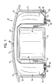
- the drawing shows a schematic cross section by an airbag module according to the invention.
- an airbag module for a vehicle steering wheel is shown, the one Pot-shaped receiving housing 10 with a front wall 12 and one piece molded on it, circumferential side wall 14.
- the front wall 12 has a plurality of weakening zones 16 that define a plurality of opening flaps 18 that Form sections of the front wall 12.
- the gas bag module also has a cup-shaped diffuser 20, which is inserted into the receiving housing 10 from the open bottom side 22 thereof is.
- the diffuser has a radial flange 24 at its bottom end extends outwards to the side wall 14 and in this area a bent, has axially extending end edge 26 on which it has a snap connection 28 or a screw connection 30 is fixedly attached to the receiving housing 10.
- the flange 24 closes approximately flush with the lower edge of the side wall 14 and forms an annular bottom for closing the receiving housing 10, because the diffuser 20 is open on the back and thus has one Inlet opening for the gas generator 42.
- the diffuser is a sheet metal part that has several flow openings and from the gas generator laterally as well as axially is spaced.
- a closed space is formed, which as an annular receiving space 32 for an airbag 34 is designated.
- an annular receiving space 32 for an airbag 34 is designated.
- a retaining ring 36 is arranged on the back protruding threaded bolt 38 can be attached.
- the retaining bolts 38 extend through openings in flange 24.
- a bottom open gas generator space 40 is formed. From the bottom, the Assembly simply inserted a gas generator 42 into the gas generator space 40.
- the Gas generator 40 has a cylindrical shape and one first toward the Bottom and then radially outward fastening flange 44.
- the mounting flange 44 is an elastomeric damping member 46 with the Gas generator 42 coupled to the gas generator 42 vibration-isolated in To accommodate gas generator room 40.
- the mounting flange 44 is on the bottom side directly on the flange 24, and the bolts 38 also protrude corresponding openings in the mounting flange 44.
- the bolts 38 can also be used to attach the entire module to the Steering wheel can be used.
- the gas bag module shown is very simple and consists of very few, easy to assemble parts.
- the stability of the housing is achieved by the diffuser 20, the flange 24 of the bottom of the receiving housing forms and closes this.
- the gas bag module is very short axially because the gas generator 42 is stationary not in front of the receptacle housing.
Abstract
Description
Die Erfindung betrifft ein Gassack-Modul, mit einem Aufnahmegehäuse für einen Gassack, einem Gasgenerator und einem topfförmigen Diffusor, der den Gasgenerator umgibt und einen Aufnahmeraum für den Gassack beschränkt.The invention relates to an airbag module, with a receiving housing for a gas bag, a gas generator and a cup-shaped diffuser that the Gas generator surrounds and limited a space for the gas bag.
Derartige Gassack-Module werden insbesondere im Lenkrad des Fahrzeugs eingesetzt. Der Diffusor begrenzt radial innenseitig einen ringförmigen Aufnahmeraum für den Gassack, wobei der Aufnahmeraum radial außenseitig von einer Seitenwand des Aufnahmegehäuses definiert ist. Im Stand der Technik wird am Aufnahmegehäuse ein Bodenblech befestigt, an dem der Diffusor, der Gasgenerator und ein ggf. im Inneren des Gassacks angeordneter Haltering befestigt sind.Such gas bag modules are used in particular in the steering wheel of the vehicle used. The diffuser delimits an annular radially on the inside Receiving space for the gas bag, the receiving space being radially outside of a side wall of the receiving housing is defined. In the prior art a base plate is attached to the receiving housing, on which the diffuser, the Gas generator and a retaining ring possibly arranged in the interior of the gas bag are attached.
Aufgabe der Erfindung ist es, ein Gassack-Modul zu schaffen, das einfacher aufgebaut ist und das vor allem eine sehr einfache Montage erlaubt.The object of the invention is to provide an airbag module that is easier is constructed and, above all, allows very simple assembly.
Dies wird bei einem Gassack-Modul der eingangs genannten Art dadurch erreicht, daß der Diffusor einen radialen Flansch hat, mit dem er unmittelbar am Aufnahmegehäuse befestigt ist und der einen ringförmigen Boden zum Verschließen des Aufnahmegehäuses bildet, und daß der Diffusor in das Innere des Aufnahmegehäuses ragt und einen von Seiten des Bodens offenen Gasgeneratorraum bildet.This is the case with an airbag module of the type mentioned at the outset achieved that the diffuser has a radial flange with which it is directly on Receiving housing is attached and an annular bottom for Closing the receptacle forms, and that the diffuser inside of the receiving housing and a gas generator room open from the bottom forms.
Beim erfindungsgemäßen Gassack-Modul bildet der Diffusor den Boden für das Aufnahmegehäuse, so daß das zuvor beschriebene Bodenblech komplett entfallen kann. Da dadurch der Diffusor auch den Abschluß des Aufnahmegehäuses bildet, kann ein von der Seite des Bodens aus offener Gasgeneratorraum entstehen, so daß der Gasgenerator am Ende der Montage einfach bodenseitig in den Gasgeneratorraum, sozusagen als letztes zu montierendes Teil, eingeführt werden kann. Damit ist es auch möglich, die gewünschte möglichst lange Trennung im Handling zwischen Gasgenerator und dem restlichen Gassack-Modul zu gewährleisten.In the gas bag module according to the invention, the diffuser forms the base for the receptacle so that the base plate described above is complete can be omitted. As a result, the diffuser also closes the housing forms, a gas generator room open from the side of the floor arise, so that the gas generator at the end of the assembly simply in the bottom introduced the gas generator room, so to speak as the last part to be assembled can be. It is also possible to make the desired as long as possible Separation in handling between the gas generator and the remaining gas bag module to ensure.
Der Gasgenerator ist bodenseitig in den Gasgeneratorraum eingeführt und am Flansch des Diffusors befestigt. Die Befestigung von unten schafft eine gute Zugänglichkeit für die Befestigungsmittel. Vorzugsweise liegt der Gasgenerator vollständig im Gasgeneratorraum.The gas generator is inserted into the bottom of the gas generator room and on Flange of the diffuser attached. The attachment from below creates a good one Accessibility for the fasteners. The gas generator is preferably located completely in the gas generator room.
Der Flansch des Diffusors hat gemäß einer Ausführungsform einen umgebogenen, axialen Abschlußrand, mit dem er an der Seitenwand des Aufnahmegehäuses befestigt ist. Das Aufnahmegehäuse muß damit keinen radial einwärts ragenden Abschnitt aufweisen, der einen Teil des Bodens bildet, was die Herstellung des Aufnahmegehäuses erleichtert.According to one embodiment, the flange of the diffuser has one bent, axial end edge, with which he on the side wall of the Receiving housing is attached. The receptacle therefore does not have to be radial have inwardly projecting portion which forms part of the bottom, which the Manufacture of the receiving housing facilitated.
Das Aufnahmegehäuse besteht vorzugsweise aus einer umlaufenden Seitenwand und einer einstückig daran angeformten Frontwand mit einer vorgegebenen Öffnungsklappe zum Austritt des Gassacks. Die Öffnungsklappe wird dadurch gebildet, daß die Frontwand vorgegebene Aufreißlinien mit Materialschwächungszonen besitzt. Das Gassack-Modul wird also großteils durch nur zwei einfach herzustellende Teile gebildet, nämlich durch das Aufnahmegehäuse, welches topfförmig ausgebildet ist, und den topfförmigen Diffusor, der von der Rückseite her eingeschoben wird und dessen Flansch an der Seitenwand des Aufnahmegehäuses befestigt ist.The receiving housing preferably consists of a circumferential Side wall and a one-piece molded front wall with a predetermined opening flap for the exit of the gas bag. The opening flap is formed in that the front wall with predetermined tear lines Has material weakening zones. The gas bag module is largely through only two easy-to-manufacture parts are formed, namely by the receiving housing, which is cup-shaped, and the cup-shaped diffuser, the is inserted from the back and its flange on the side wall the receiving housing is attached.
Die Befestigung des Gassacks am Gassack-Modul erfolgt beispielsweise mittels eines im Inneren des Gassacks angeordneten Halterings, der am Flansch des Diffusors befestigt ist. Der Haltering hält dann den Rand der sogenannten Einblasöffnung, über die Gas in das Innere des Gassacks einströmt, am Gassack-Modul.The gas bag is attached to the gas bag module, for example by means of a retaining ring arranged in the interior of the gas bag, which is on the flange the diffuser is attached. The retaining ring then holds the edge of the so-called Injection opening, through which gas flows into the interior of the gas bag, on the gas bag module.
Bevorzugt wird das Gassack-Modul auch mit einem Schwingungsdämpfer bestückt, indem der Gasgenerator über ein elastomeres Dämpfungsteil mit seinem Befestigungsflansch verbunden ist. Im Inneren des Diffusors kann dann der Gasgenerator ungestört schwingen, denn er besitzt einen ausreichenden Abstand zum Diffusor.The gas bag module is also preferred with a vibration damper equipped by the gas generator via an elastomeric damping part with its Mounting flange is connected. The inside of the diffuser can then Swing the gas generator undisturbed because it is at a sufficient distance to the diffuser.
Weitere Merkmale und Vorteile der Erfindung ergeben sich aus der nachfolgenden Beschreibung und aus der nachfolgenden Zeichnung, auf die Bezug genommen wird. Die Zeichnung zeigt einen schematischen Querschnitt durch ein erfindungsgemäßes Gassack-Modul.Further features and advantages of the invention result from the following description and from the following drawing, on the Reference is made. The drawing shows a schematic cross section by an airbag module according to the invention.
In Figur 1 ist ein Gassack-Modul für ein Fahrzeuglenkrad dargestellt, das ein
topfförmiges Aufnahmegehäuse 10 mit einer Frontwand 12 und einer einstückig
daran angeformten, umlaufenden Seitenwand 14 aufweist. Die Frontwand 12 hat
mehrere Schwächungszonen 16, die mehrere Öffnungsklappen 18 definieren, die
Abschnitte der Frontwand 12 bilden.In Figure 1, an airbag module for a vehicle steering wheel is shown, the one
Pot-shaped receiving housing 10 with a
Das Gassack-Modul weist darüber hinaus einen topfförmigen Diffusor 20 auf,
der von der offenen Bodenseite 22 des Aufnahmegehäuses 10 in dieses eingeführt
ist. Der Diffusor hat an seinem bodenseitigen Ende einen radialen Flansch 24, der
nach außen bis zur Seitenwand 14 ragt und in diesen Bereich einen umgebogenen,
axial verlaufenden Abschlußrand 26 besitzt, an dem er über eine Rastverbindung
28 oder eine Schraubverbindung 30 fest am Aufnahmegehäuse 10 befestigt ist.
Der Flansch 24 schließt in etwa bündig mit dem unteren Rand der Seitenwand 14
ab und bildet einen ringförmigen Boden zum Verschließen des Aufnahmegehäuses
10, denn der Diffusor 20 ist rückseitig offen und hat somit eine
Einführöffnung für den Gasgenerator 42. Der Diffusor ist ein Blechteil, das
mehrere Durchströmöffnungen hat und vom Gasgenerator seitlich wie auch axial
beabstandet ist. Zwischen dem Aufnahmegehäuse 10 und dem Diffusor 20 wird
ein abgeschlossener Raum gebildet, der als ringförmiger Aufnahmeraum 32 für
einen Gassack 34 bezeichnet wird. Im Inneren des Gassacks 34, am Rand der
sogenannten Einblasöffnung ist ein Haltering 36 angeordnet, an dem rückseitig
vorstehende Gewindebolzen 38 angebracht sein können. Die Haltebolzen 38
erstrecken sich durch Öffnungen im Flansch 24.The gas bag module also has a cup-
Dadurch, daß der Diffusor 20 bodenseitig offen ist, wird ein bodenseitig
offener Gasgeneratorraum 40 gebildet. Von der Bodenseite aus wird am Ende der
Montage einfach ein Gasgenerator 42 in den Gasgeneratorraum 40 eingeführt. Der
Gasgenerator 40 hat eine zylindrische Gestalt und einen zuerst in Richtung des
Bodens und anschließend radial nach außen verlaufenden Befestigungsflansch 44.
Der Befestigungsflansch 44 ist über ein elastomeres Dämpfungsteil 46 mit dem
Gasgenerator 42 gekoppelt, um den Gasgenerator 42 schwingungsentkoppelt im
Gasgeneratorraum 40 unterzubringen. Der Befestigungsflansch 44 liegt bodenseitig
unmittelbar am Flansch 24 an, und die Schraubbolzen 38 ragen auch durch
entsprechende Öffnungen im Befestigungsflansch 44.Characterized in that the
Die Schraubbolzen 38 können auch zur Befestigung des gesamten Moduls am
Lenkrad verwendet werden.The
Das gezeigte Gassack-Modul ist sehr einfach aufgebaut und besteht aus sehr
wenigen, einfach zu montierenden Teilen. Die Stabilität des Aufnahmegehäuses
wird durch den Diffusor 20 erzielt, dessen Flansch 24 den Boden des Aufnahmegehäuses
bildet und dieses schließt.The gas bag module shown is very simple and consists of very
few, easy to assemble parts. The stability of the housing
is achieved by the
Das Gassack-Modul baut axial sehr kurz, denn der Gasgenerator 42 steht
bodenseitig nicht gegenüber dem Aufnahmegehäuse vor.The gas bag module is very short axially because the
Claims (6)
daß der Diffusor (20) in das Innere des Aufnahmegehäuses (10) ragt und einen von Seiten des Bodens aus offenen Gasgeneratorraum (40) bildet.The gas bag module,
that the diffuser (20) projects into the interior of the receiving housing (10) and forms an open gas generator space (40) from the bottom.
Applications Claiming Priority (2)
| Application Number | Priority Date | Filing Date | Title |
|---|---|---|---|
| DE20104044U DE20104044U1 (en) | 2001-03-08 | 2001-03-08 | Airbag module |
| DE20104044U | 2001-03-08 |
Publications (2)
| Publication Number | Publication Date |
|---|---|
| EP1238871A2 true EP1238871A2 (en) | 2002-09-11 |
| EP1238871A3 EP1238871A3 (en) | 2003-07-16 |
Family
ID=7954025
Family Applications (1)
| Application Number | Title | Priority Date | Filing Date |
|---|---|---|---|
| EP02004304A Withdrawn EP1238871A3 (en) | 2001-03-08 | 2002-02-28 | Airbag module |
Country Status (3)
| Country | Link |
|---|---|
| US (1) | US20020125704A1 (en) |
| EP (1) | EP1238871A3 (en) |
| DE (1) | DE20104044U1 (en) |
Cited By (1)
| Publication number | Priority date | Publication date | Assignee | Title |
|---|---|---|---|---|
| US9687646B2 (en) | 2007-07-05 | 2017-06-27 | Baxter International Inc. | Peritoneal dialysis connection system and method for using ultraviolet light emitting diodes |
Families Citing this family (5)
| Publication number | Priority date | Publication date | Assignee | Title |
|---|---|---|---|---|
| DE10230140A1 (en) * | 2002-07-04 | 2004-01-15 | Trw Automotive Safety Systems Gmbh & Co. Kg | Airbag module |
| DE102004008043A1 (en) * | 2004-02-19 | 2005-09-15 | Autoliv Development Ab | Airbag module with vibration damped gas generator has vibration damping holder with head acting as stop for gas generator for lateral movement of gas generator in plane of flange sections |
| EP2995512B1 (en) * | 2014-09-11 | 2017-11-15 | Dalphi Metal España, S.A. | Airbag module, retainer and assembly of airbag module and steering wheel |
| JP6753380B2 (en) * | 2017-09-28 | 2020-09-09 | 豊田合成株式会社 | Airbag device |
| JP6948010B2 (en) | 2017-11-08 | 2021-10-13 | Joyson Safety Systems Japan株式会社 | Airbag device |
Citations (4)
| Publication number | Priority date | Publication date | Assignee | Title |
|---|---|---|---|---|
| GB2341359A (en) * | 1998-09-08 | 2000-03-15 | Takata | Airbag arrangement for absorbing oscillations |
| EP1010589A2 (en) * | 1998-12-18 | 2000-06-21 | Delphi Technologies, Inc. | Airbag module for vehicles |
| US6092834A (en) * | 1998-02-05 | 2000-07-25 | Breed Automotive Technology, Inc. | Airbag module |
| EP1026050A2 (en) * | 1999-02-05 | 2000-08-09 | TRW Automotive Safety Systems GmbH & Co. KG | Airbag module dampening vibrations |
Family Cites Families (2)
| Publication number | Priority date | Publication date | Assignee | Title |
|---|---|---|---|---|
| US5762360A (en) * | 1996-10-31 | 1998-06-09 | General Motors Corporation | Air bag assembly |
| US6089600A (en) * | 1998-09-24 | 2000-07-18 | General Motors Corporation | Integral gas direction device for an air bag |
-
2001
- 2001-03-08 DE DE20104044U patent/DE20104044U1/en not_active Expired - Lifetime
-
2002
- 2002-02-28 EP EP02004304A patent/EP1238871A3/en not_active Withdrawn
- 2002-03-04 US US10/090,393 patent/US20020125704A1/en not_active Abandoned
Patent Citations (4)
| Publication number | Priority date | Publication date | Assignee | Title |
|---|---|---|---|---|
| US6092834A (en) * | 1998-02-05 | 2000-07-25 | Breed Automotive Technology, Inc. | Airbag module |
| GB2341359A (en) * | 1998-09-08 | 2000-03-15 | Takata | Airbag arrangement for absorbing oscillations |
| EP1010589A2 (en) * | 1998-12-18 | 2000-06-21 | Delphi Technologies, Inc. | Airbag module for vehicles |
| EP1026050A2 (en) * | 1999-02-05 | 2000-08-09 | TRW Automotive Safety Systems GmbH & Co. KG | Airbag module dampening vibrations |
Cited By (1)
| Publication number | Priority date | Publication date | Assignee | Title |
|---|---|---|---|---|
| US9687646B2 (en) | 2007-07-05 | 2017-06-27 | Baxter International Inc. | Peritoneal dialysis connection system and method for using ultraviolet light emitting diodes |
Also Published As
| Publication number | Publication date |
|---|---|
| DE20104044U1 (en) | 2001-07-12 |
| EP1238871A3 (en) | 2003-07-16 |
| US20020125704A1 (en) | 2002-09-12 |
Similar Documents
| Publication | Publication Date | Title |
|---|---|---|
| EP0622276B1 (en) | Airbag restraint system for vehicles | |
| DE102012109545A1 (en) | "Housing for a fan or fan" | |
| DE102012002433B4 (en) | Damper bearing for a piston rod of a vibration damper and motor vehicle with such a damper bearing | |
| EP2337710B1 (en) | Gas generator for an airbag module | |
| DE202014008432U1 (en) | Device for vibratory mounting of a gas generator in an airbag module | |
| DE19703767B4 (en) | Housing for the gas bag in a motor vehicle | |
| DE102017123078A1 (en) | Pressure compensation unit and assembly of a housing and a pressure compensation unit | |
| EP1238871A2 (en) | Airbag module | |
| DE19743615B4 (en) | Airbagbaueinheit | |
| EP3181418A1 (en) | Pneumatic control valve | |
| EP2542325B1 (en) | Oil mist separator comprising at least one cyclone | |
| WO2003033311A1 (en) | Housing for motor vehicle airbag | |
| EP1167742A2 (en) | Air intake filter | |
| DE102017119335A1 (en) | GASSACK MODULE FOR A VEHICLE WHEEL | |
| EP3842296A1 (en) | Vibration absorber ring and airbag module with such a vibration absorber ring | |
| DE10013472C2 (en) | Gas generator for an airbag on a motor vehicle steering wheel | |
| DE102007006571A1 (en) | Airbag module for support system for passenger of vehicle, has airbag and gas generator whereby section of airbag package lies laterally at gas producer in escaping direction behind airbag protection device | |
| DE4303694B4 (en) | Liquid filter with overflow valve | |
| EP1101662A2 (en) | Airbag gas generator operating as an oscillation damper | |
| DE19718211A1 (en) | Enclosure for front passenger airbag module | |
| EP1060957B1 (en) | Airbag module unit, and airbag module | |
| EP1937516A1 (en) | Air bag module, especially for a knee air bag | |
| DE19648137C2 (en) | Airbag module | |
| DE4003127C2 (en) | Air outlet, especially ceiling air outlet | |
| DE202006003235U1 (en) | Airbag module for support system for passenger of vehicle, has airbag and gas generator whereby section of airbag package lies laterally at gas producer in escaping direction behind airbag protection device |
Legal Events
| Date | Code | Title | Description |
|---|---|---|---|
| PUAI | Public reference made under article 153(3) epc to a published international application that has entered the european phase |
Free format text: ORIGINAL CODE: 0009012 |
|
| AK | Designated contracting states |
Kind code of ref document: A2 Designated state(s): AT BE CH CY DE DK ES FI FR GB GR IE IT LI LU MC NL PT SE TR |
|
| AX | Request for extension of the european patent |
Free format text: AL;LT;LV;MK;RO;SI |
|
| PUAL | Search report despatched |
Free format text: ORIGINAL CODE: 0009013 |
|
| AK | Designated contracting states |
Designated state(s): AT BE CH CY DE DK ES FI FR GB GR IE IT LI LU MC NL PT SE TR |
|
| AX | Request for extension of the european patent |
Extension state: AL LT LV MK RO SI |
|
| AKX | Designation fees paid | ||
| REG | Reference to a national code |
Ref country code: DE Ref legal event code: 8566 |
|
| STAA | Information on the status of an ep patent application or granted ep patent |
Free format text: STATUS: THE APPLICATION IS DEEMED TO BE WITHDRAWN |
|
| 18D | Application deemed to be withdrawn |
Effective date: 20040117 |