-
The present invention relates to a photofinishing processing
solution supply cartridge, container or packaging system, as well as a processing
system having a supply cartridge, container or packaging system that is adapted to
hold processing solution and collect spent processing or cleaning solution. More
particularly, the present invention relates to a chemical supply cartridge, container
or packaging system having an integrated silver recovery process for
photoprocessing systems.
-
Current photographic processing machines are typically large,
costly systems which are highly dependent on infrastructure, such as water supply
and access to drain(s). The quantity of chemicals used in processing photographic
materials has been historically high. Further, many processes rely on the use of
concentrated chemistry and necessitate an additional source of water. As an
added factor, almost all processors require significant infrastructure to support the
treatment of spent solution and silver recovery.
-
There are a number of chemical delivery cartridges available that
supply fresh photo-chemicals to photoprocessing machines. The machine
operators who use the photo-chemicals are typically required by law to treat the
effluent or spent processing solution from the process to reduce the level of
aqueous silver before discharging the spent processing solution or effluent to
municipal waste water treatment systems. These silver recovery treatment
systems are typically sold as add-ons to the processors and require additional
maintenance and operator intervention.
-
Current photographic processing machines are typically detached
from the apparatus, method or mechanism of silver recovery. With the additional
plumbing, solution transfer and operator intervention is required for an add-on
mechanism. With the need for additional equipment and plumbing, inefficiencies
in the overall processing system are created. Further, current photographic
processing machines which have a detached silver recovery system positioned
beside the processor define a larger overall footprint for the combined system and
are higher in cost to maintain. There also remains a greater potential for failure of
the silver recovery system and an increased likelihood for chemical exposure due
to leaks and the additional plumbing that is needed to transport the solution from
the processing machine to the detached silver recovery mechanism.
-
Further, in most current photoprocessing applications, concentrates
are supplied to the customer who then dilutes them with water to significantly
increase the volume subsequently requiring treatment. This is inconvenient or
impractical in dispersed or less conventional market places such as retail stores,
aircraft, and cruise ships since a water supply and plumbing is needed.
-
U.S. Patent No. 4,791,013 discloses a housing pack for
photographic processing solution. More specifically, U.S. Patent No. 4,791,013
discloses a container having a first chamber for holding processing solution and a
second chamber for collecting spent solution. However, in this patent the
collected waste solution is only passed through a solution absorption substance to
create a solid waste in which the amount of leachable silver in the spent solution is
unchanged. U.S. Patent No. 4,791,013 does not provide for a treatment of the
spent solution in the supply cartridge in which the concentration of leachable
silver in the spent solution is reduced with respect to the silver TCLP (Toxicity
Characteristics Leaching Procedure) test for non-hazardous waste based on U.S.
Resource Conservation and Recovery Act (RCRA) definitions so that the
customer realizes waste management advantages. Advantages with this
classification include reduced record keeping, training and cost.
-
U.S. Patent No. 5,199,594 discloses a container having a flexible
inner bag which is divided into a liquid storage chamber and a used-liquid storage
chamber. However, like U.S. Patent No. 4,791,013, U.S. Patent No. 5,199,594
does not provide for a supply cartridge which both collects and renders spent
solution RCRA non-hazardous which can be subsequently transported and treated
with reduced regulatory control.
-
Federal Waste management regulations define the hazardous/non-hazardous
characteristics of most photoprocessing solutions through the Toxicity
Characteristics Leaching Procedure (TCLP) for silver. If a solution is negative in
this test, it is not a format characteristic RCRA hazardous waste, which allows
numerous handling exemptions such as the ability to transport the solution by a
non-hazardous hauler without excessive paperwork. Within the context of the
present invention, leachable silver is defined as the analysis of the amount of
silver that will leach from a solid or the amount of silver that is present in a liquid.
The leaching test is used to determine if the material is a hazardous waste by using
the Toxicity Characteristic Leaching Procedure (TCLP) (EPA Test Method 1311).
Solids are reduced in size and subjected to a dilute acid solution. The leachate is
then analyzed to determine the amount of silver extracted from the solid. Liquids
are directly analyzed for total recoverable silver.
-
There is presently a need for the improvement of the chemical
supply system so that photoprocessing machines can utilize a silver recovery
technique with a chemical supply cartridge without the need for a separate or
detached silver recovery device. That is, there is presently a need for a chemical
supply cartridge or container that can be retrofitted to an existing processor or can
be fluidly connected to a new or stand-alone processor, which is adapted to supply
processing solution to the processor, as well as collect and treat spent solution for
the purpose of reducing TCLP leachable silver in the spent solution.
-
Recent advancements in the minimization of solution usage in
photoprocessing has made delivering and removing of working strength
photographic chemistry economically viable. The present invention provides for a
chemical management cartridge that both delivers fresh chemistry and receives,
accumulates and renders spent effluent in a manner which permits the spent
effluent to be disposed of in a less-regulated manner. Within the context of the
present invention, spent or waste solution or effluent refers to processing solution
which has gone through a photoprocessing cycle and is no longer resident in the
processor (or processing equipment). For a stand-alone or new processor, the
integration of the spent solution management with the chemical supply delivery
system gives the practical advantage of permitting a processing of photographic
materials without direct connections to a water supply or drain. It also enables a
single service organization to both deliver supply solutions and remove spent
solutions. For an existing processor, the cartridge of the present invention can be
retrofitted to the processor, be adapted to deliver processing solution to the
processor, and used to collect and treat spent solution from the processor. If the
existing processor includes the necessary plumbing, the cartridge of the present
invention can be adapted to reduce leachable silver in the spent solution and
deliver the spent solution to an existing plumbing system without requiring special
handling.
-
A preferred embodiment of the present invention utilizes the ability
to deliver working strength chemistry (i.e. for use in a minilab where "solution
volume in" equals "collected solution volume" for de-silvering), thereby
eliminating dilution errors during operation. A secondary advantage is an
improvement in portability and the reduction of the "footprint" of the processor
that allows processing of film to occur in less conventional market places,
including mobile locations such as an aircraft or cruise ships. By leveraging these
advantages, placement of the photoprocessor machines in dispersed or less
traditional retail locations is permitted.
-
The system of the present invention also enables an apparently dry
operation, where contact with the processing chemicals is minimized and the
operator has limited opportunity for chemical exposure. This is beneficial in non-traditional
photofinishing locations where there is a preference towards a semi-hands
free operation where the supply and spent solutions need to be invisible to
the users and customers of the users. The reuse of an external cartridge shell
provides for an efficient use of materials, which offers an environmental benefit
along with potential cost savings.
-
Therefore, the present invention integrates the collection of waste
solution and the minimization of leachable silver from the spent solution within a
photoprocessing solution supply system. The advantage of the present invention
over conventional approaches is that it provides for a convenient method and
system for silver recovery with minimal operator interaction with the equipment.
Further, it facilitates the creation of a spent or waste solution that is less regulated
for transport and disposal. Furthermore, it reduces chemical exposure for the
operator and reduces the chances of error with respect to silver recovery. The
invention also reduces the floor space required for the processor due to the fact
that the silver recovery system is integrated with the processor rather than being
attached separately.
-
The present invention accordingly provides for a photofinishing
processing solution supply cartridge which is adapted to hold processing solution
therein, and collect spent or waste processing solution and leachable silver in the
collected spent processing solution. In the method and system of the present
invention, an apparatus can be used as a chemical supply delivery system for
processing photosensitive media, and for removing or reducing the amount of
leachable silver in the spent processing solution. In a preferred embodiment, the
invention can be utilized in photoprocessing machines that use a cartridge-style
processing solution or chemical supply system. Thus, the cartridge of the
invention could be designed to be used within a system in which a single entity
delivers fresh chemistry and collects the recoverable silver for recovery or
treatment, as opposed to providing two distinct entities to effect these operations
or services. In a further embodiment, the cartridge can be retrofitted into an
existing processor and the treated spent solution can be supplied in a less-regulated
manner to an existing plumbing system.
-
The present invention therefore relates to a photofinishing
processing solution supply cartridge that comprises at least one processing
solution chamber or vessel for holding processing solution therein; and at least
one spent or waste solution chamber or vessel that is adapted to collect spent or
waste solution from a photofinishing system associated with the supply cartridge.
The at least one spent or waste solution chamber comprises a silver removal
device that reduces an amount of leachable silver contained in the spent solution.
-
The present invention further relates to a photofinishing processing
solution supply cartridge that comprises at least one processing solution chamber
for holding processing solution therein, and at least one spent solution chamber or
vessel that is adapted to collect spent solution from a photofinishing system
associated with the supply cartridge. The at least one spent solution vessel or
chamber provides a silver precipitating agent. The silver precipitating agent is
adapted to react with the spent solution in the vessel or chamber to form a
removable silver sludge in the vessel or chamber.
-
The present invention further relates to a photofinishing processing
solution supply cartridge which comprises at least one processing solution
chamber for holding processing solution therein and supplying processing solution
to a photofinishing system which is fluidly associated with the supply cartridge;
and a silver removal device for removing silver from spent processing solution of
the photofinishing system associated with the supply cartridge to provide a spent
solution that is substantially free of leachable silver.
-
The present invention further relates to a processing system
comprising a processor for processing photosensitive media therein; and a
processing solution supply cartridge adapted to supply processing solution to the
processor and collect spent processing solution from the processor. The
processing solution supply cartridge has at least one chamber for holding the
processing solution therein and a silver removal device for reducing an amount of
leachable silver in the spent processing solution, to provide a spent solution that is
substantially free of leachable silver.
-
The present invention further relates to a processing system that
comprises a processor for processing photosensitive media therein; and a
processing solution supply cartridge that is adapted to supply processing solution
to the processor and collect spent processing solution from the processor. The
processing solution supply cartridge comprises at least one processing solution
chamber or vessel for holding processing solution therein; and at least one spent
solution chamber or vessel for collecting spent processing solution from the
processor. The at least one spent solution chamber or vessel comprises a silver
removal device that reduces an amount of leachable silver contained in the spent
solution to provide a spent solution substantially free of leachable silver.
-
The present invention further relates to a processing system that
comprises a processor for processing photosensitive media therein; and a
processing solution supply cartridge that is adapted to supply processing solution
to the processor and collect spent processing solution from the processor. The
processing solution supply cartridge comprises at least one processing solution
chamber, vessel or area that holds processing solution therein, and at least one
spent solution vessel, chamber or area that is adapted to collect the spent solution
from the processor. The at least one spent solution vessel, chamber or area
comprises a silver precipitating agent. The silver precipitating agent is adapted to
react with the spent solution in the vessel, chamber or area to form a removable
silver sludge in the vessel.
-
The present invention further relates to a method of removing
silver from photofinishing processing solution which comprises the steps of
feeding spent processing solution from a photofinishing system to a supply
cartridge, with the supply cartridge having incorporated therein at least one
chamber for holding fresh processing solution and at least one further chamber
adapted to collect the spent processing solution; and reducing an amount of
leachable silver in the spent processing solution collected in the at least one
further chamber.
-
The present invention further relates to a method of processing
photosensitive media which comprises the steps of supplying processing solution
from a supply cartridge to a processor for processing a photosensitive media in the
processor, with the supply cartridge having a first area for holding fresh
processing solution; feeding spent processing solution from the processor to a
second area of the supply cartridge; and reducing an amount of leachable silver in
the spent processing solution in the second area of the supply cartridge.
-
The present invention further relates to a container for
photographic processing solution. The container comprises a rigid and reusable
outer shell which is adapted to be opened to access an interior of the shell; and at
least two internal chambers positioned in the interior of the shell and accessible
when the outer shell is opened. A first chamber of the at least two internal
chambers is adapted to supply fresh working strength photochemistry, a
concentrated mixture of chemistry or cleaning solution to a processing machine
which is operationally associated with the container; and a second chamber of the
at least two internal chambers is adapted to collect spent processing solution or
cleaning solution from the processing machine and reduce an amount of silver in
the spent processing solution or cleaning solution.
-
The present invention further relates to a solution container for a
photoprocessing machine which is adapted to supply water, a mixture of
concentrated processing solution, and/or working strength processing solution to
the photoprocessing machine, and collect and treat spent solution from the
photoprocessing machine. The container comprises a rigid and reusable outer
shell.
-
The present invention further relates to a method of processing
photographic media which comprises the steps of fluidly connecting a container to
a photoprocessing machine, with the container comprising a rigid and reusable
outer shell that is adapted to hold processing solution and collect spent solution;
supplying processing solution from the container to the photoprocessing machine;
collecting spent solution from the photoprocessing machine in the container; and
treating the spent solution to create a spent solution which is substantially free of
leachable silver.
-
The present invention further relates to a method of supplying
photographic processing solution to a processor which comprises the steps of:
placing a processing solution supply cartridge having processing solution therein
on a movable fixture member in a manner in which a valve of the supply cartridge
and the supply cartridge are in an upright position; and moving the fixture
member having the supply cartridge thereon to an operating position in which the
supply cartridge is placed in an inverted position to permit a supply of processing
solution through the valve from the supply cartridge to a processor which is
fluidly connected to the supply cartridge.
- Fig. 1 schematically illustrates a processing system including a
processor and a supply cartridge in accordance with the present invention;
- Fig. 2 schematically illustrates one embodiment of a supply
cartridge utilized in the processing system of Fig. 1;
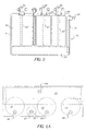
- Fig. 3 schematically illustrates a further embodiment of a supply
cartridge in accordance with the present invention;
- Figs. 4A-4B respectively illustrate an end view and a side view of a
still further embodiment of the supply cartridge of the present invention;
- Fig. 5 illustrates a still further embodiment of a supply cartridge of
the present invention;
- Fig. 6A-6C respectively illustrate a top view, a side view and an
end view of a still further embodiment of the cartridge of the present invention;
- Figs. 7A-7B illustrate an example of an attachment feature for a
supply cartridge in accordance with the present invention; and
- Figs. 8A-8C illustrate a supply cartridge in accordance with the
present invention having containers with baffles.
-
-
Referring now to the drawings, wherein like reference numerals
represent identical or corresponding parts throughout the several views, a
processor 5 is schematically shown in Fig. 1. Processor 5 can be a known
processor having individual processing tanks, areas or sections, and a
photosensitive media path which passes through the appropriate sections for
processing photosensitive media in a known manner. Processor 5 is further
adapted to receive fresh processing solution from a supply cartridge, or container
or packaging system 7. More specifically, as is illustrated in Fig. 1, and using
cartridge 7 of Figs. 1 and 2 as an example, processor 5 is adapted to be
operationally or fluidly connected with processing solution or chemical supply
cartridge or container 7. With regard to the details of chemical supply cartridge or
container 7, reference is made to Fig. 2.
-
As illustrated in Fig. 2, chemical supply cartridge 7 can include a
rigid and reusable outer shell 9 that can be opened to gain access to or facilitate
the removal of internal chambers, vessels, containers or areas 11a, 11b, 11c, 11d
and 11e. Rigid shell 9 can be made of a combination of materials including but
not limited to LLDPE (linear low density polyethylene), nylon, EVOH (Ethylene
vinyl Alcohol), (Saran PVDC Polyvinlyadene Chloride) or HDPE (High density
polyethylene). In a preferred embodiment outer shell 9 can be either a corrugated
fiber board, HDPE or polypropylene.
-
As is also shown in Fig. 2, chemical supply cartridge 7 includes
valves 14a, 14b, 14c, 14d, 14e and 14f which can be either internal or external to
rigid outer shell 9 and can be quick release valves or release fittings for fluidly
connecting the cartridge to the processor in a known manner. Valves 14a-14d are
respectively associated with chambers 11a-11d, while valves 14e-14f are
associated with chamber 11e.
-
As an example, chamber or vessel 11a can hold and/or supply
developer to processor 5; chamber or vessel 11b can hold and /or supply fresh
ferrous/ferric solution to processor 5; chamber or vessel 11c can hold and/or
supply fixer solution to processor 5; and chamber or vessel 11d can hold and/or
supply a final rinse or cleaning solution to processor 5. Chambers 11a-11d are
provided in an area 15 of cartridge 7 that can be generally defined as a processing
solution holding and/or supplying area. Depending on where the cartridge is to be
used (i.e. retrofitted to an existing processor or minilab, or attached to a new
processor or minilab) chambers 11a-11d can hold fresh working strength
photochemistry therein, a mixture of concentrated chemistry and/or cleaning
solution such as water. In a preferred embodiment, chambers 11a-11d hold
working strength chemistry in a manner in which "solution volume in" equals
"collected solution volume".
-
Cartridge 7 further includes chamber or vessel 11e which is a silver
removal device or mechanism. Unlike fresh processing solution chambers 11a-11d,
vessel 11e includes valve or release fitting 14e for discharge of a reduced
leachable silver spent or waste processing solution, and valve 14f which is
adapted to receive spent or waste processing solution from processor 5 for
treatment. Silver removal chamber 11e is provided in an area 17 of cartridge 7
which can generally be defined as a spent solution collection and leachable silver
removal area.
-
Thus, supply cartridge 7 essentially defines a first area 15 which is
adapted to hold fresh processing solution, and a second area 17 which is adapted
to collect spent or waste processing solution or used cleaning solution, and by a
selected treatment, reduce the amount of leachable silver from the spent
processing solution or the used cleaning solution in a manner which will be
described later.
-
It is noted that the number of supply chambers and spent solution
chambers is not limited to the number shown in Fig. 1. It is recognized that the
number of supply chambers and spent solution chambers utilized is based on
design considerations and the type of processing cycle desired.
-
With reference to Fig. 1, cartridge 7 supplies fresh photographic
processing solution or chemistry (working strength or concentrated mixture
depending on the type of processing and the processor) to processor or
photoprocessing machine 5, and recovers, reduces or removes leachable silver
from the spent or waste processing or cleaning solution. This is achieved by an
integration of a solution supply system in the form of supply cartridge 7 with a
method of silver recovery of photographic processing solution for a film or paper
processor. Thus, during use of a photofinishing system as schematically shown in
Fig. 1, media is supplied to processor 5 and processed in a known manner. During
processing, selected fresh processing solution, chemicals or cleaning solution are
selectively supplied from chambers 11a-11d via valves 14a-14d. After
processing, spent processing solution or cleaning solution is circulated via, for
example, a spent processing solution conduit or line 20 to valve 14f of chamber
11e.
-
In a preferred embodiment, chamber 11e would house or be in the
form of a "silver removal device". The silver removal device could utilize one of
several known silver recovery techniques such as but not limited to metallic
replacement technologies, ion exchange resin or TMT (see, for example, U.S.
Patent Nos. 5,288,728; 5,496,474 and 5,759,410). The use of a silver removal
device permits the spent processing solution to pass through the device and after a
fixed time period the silver contained in the spent processing solution is collected
within the trapping matrix contained in the silver removal device. Substantially,
leachable silver-free spent processing solution or cleaning solution is then passed
via valve 14e and a discharge line 22 to a sewer in a less regulated manner, or can
be collected as a less-regulated waste based on U.S. RCRA limits for leachable
silver.
-
Within the context of the present invention, a substantially
leachable silver-free spent solution refers to the fact that the spent solution can be
disposed of or handled in a less-regulated manner per U.S. RCRA legislation. As
an example, the combined waste effluent of a typical minilab contains 3500 ppm
of silver. With a supply cartridge in accordance with the present invention having
an integrated silver removal device as described above, the amount of silver in the
spent solution is recovered, removed, or reduced to create a substantially
leachable silver-free spent solution at or below 5 ppm of silver, which is presently
the U.S. Federal Standard 40 CFR 241.24(a).
-
In the event cartridge 7 is retrofitted or attached onto an existing
processor or processing machine, it is likely that plumbing leading toward a sewer
system exists. In that case, cartridge 7 of the present invention can be attached to
a discharge line 22 (Fig. 1) to pass the substantially leachable silver-free spent
solution to the sewer line or the like as regulations permit. Of course, the present
invention is not limited thereto, and as will be described later, other treatment and
disposal methods depending on whether you retrofit the cartridge to an existing
processor or use a stand-alone processor are possible. In either case, however, the
present invention provides for a convenient cartridge which supplies processing
solution to a processor, collects spent solution, and creates less-regulated waste
based on present U.S. Federal Standards 40 CFR 241.24(a).
-
When supply chambers 11a-11d are empty, chamber 11e or the
"silver removal device" within chamber 11e may be detached or removed from
cartridge 7 and sent to a refiner to enable a cost effective shipment and recovery
of the silver. As an alternative, the entire cartridge 7 can be detached or removed
from processor 5 and shipped to the refiner. It is, however, recognized that the
removal of the silver removal device, chamber 11e or cartridge 7 can be done at
other times which are convenient to the photofinisher.
-
As an alternative embodiment, the silver-bearing spent processing
solution can be supplied via line 20 to chamber 11e in the same manner as the
embodiment discussed above, and chamber 11e can include a silver precipitating
agent or silver recovery agent instead of a "silver removal device". The agent
would be allowed to react with the aqueous silver in chamber 11e to create a
silver-sludge which can be later separated for the silver content by an outside
service provider or machine operator and can be disposed of and transported as
less-regulated waste.
-
More specifically, the solution can be stored within chamber 11e
having a silver recovery agent such as steel wool, TMT, ion exchange material
and/or resin, etc. The silver recovery agent can also be, but is not limited to, a
compound that can form a sparingly soluble salt of silver ion, such as iodide,
organic thiols, TMT, etc. In this alternative embodiment, discharge line 22 and
valve 14e would not be required. Such an embodiment would be preferably used
on a stand-alone processor such as a mini-lab in a retail store, where appropriate
plumbing and sewer lines do not exist.
-
As noted above, in the present invention, supply cartridge 7 is
comprised of at least one internal chamber or vessel 11a-11d of processing
solution and at least one internal chamber or vessel 11e for the collection of silver
from the spent processing solution. As also described above, in a preferred
embodiment, chamber 11e would include or define a silver removal device or
mechanism. This silver removal device could utilize one of several known
recovery techniques noted above, such as but not limited to metallic replacement
technologies, ion exchange material and/or resin or TMT. The silver removal
device provided in, incorporated into or formed by chamber 11 e would permit the
spent processing solution or effluent to pass through it and after a fixed time
period, the silver contained in the waste processing solution is collected within,
for example, a trapping matrix contained in the silver removal device.
Substantially leachable silver-free spent processing solution is then passed to a
sewer or can be collected as less-regulated waste based on current U.S.
Government Standards.
-
The present invention therefore provides for an improved and
convenient photoprocessing system that includes a silver recovery system within a
processing solution or chemical delivery cartridge. With the silver recovery
process coupled with solution supply, the maintenance of the silver recovery
becomes easier for the customer.
-
Referring now to Fig. 3, a further embodiment of a supply cartridge
in accordance with the present invention is shown. More specifically, Fig. 3
illustrates supply cartridge 7a which includes rigid outer shell 9 similar to the shell
illustrated in Fig. 2. As previously described, shell 9 can be opened to gain access
to or facilitate the removal of internal chambers.
-
Further, like supply cartridge 7 of Fig. 2, supply cartridge 7a of
Fig. 3 includes internal supply chamber 11 a with valve 14a which can house
and/or supply, for example, developer solution; internal supply chamber 1 1b with
valve 14b which can house and/or supply, for example, ferrous/ferric solutions;
internal supply chamber 11c with valve 14c which can house and/or supply, for
example, fixer solution; and internal supply chamber 11d with valve 14d which
can house and/or supply, for example, a final rinse or cleaning solution.
-
One difference between cartridge 7 of Fig. 2 and cartridge 7a of
Fig. 3 relates to the positioning of spent solution chamber 11e. In the embodiment
of Fig. 3, a spent solution chamber 11 e' which extends over each of supply
chambers 11a-11d is shown. In cartridge 7a as shown in Fig. 3, the silver removal
system is in the form of a silver precipitating agent 50 within chamber 11e'. In the
case of using a silver precipitating reagent, chamber 11e' would include a valve
14f' which receives spent processing solution from processor 5 as described in
Fig. 1, but would not require a discharge line or discharge valve. With the use of
this embodiment and as described above, the silver precipitating agent reacts with
the spent processing solution so as to provide for a silver sludge that can be
removed from the supply cartridge in a less-regulated manner. This embodiment
is most preferably used on a stand-alone processor where working strength
chemistry is used and which is located in an area that may not have appropriate
on-site plumbing and/or sewer facilities.
-
Therefore, in the same manner as described with respect to the
embodiment of Fig. 2, cartridge 7a of Fig. 3 is a cartridge that can be used to
supply and remove all photoprocessing chemicals from a photoprocessing
machine such as processor 5 of Fig. 1. Also in the same manner as the
embodiment of Fig. 2, cartridge 7a can be comprised of a rigid external shell that
encloses at least one internal chamber (in Fig. 3 internal chambers 11a-11d are
shown) of supply solution, and at least one internal chamber 11e' for the collection
of spent solution. Chambers 11a-11d as well as chamber 11e' may be removable
to enable refilling with fresh solutions and reuse of the cartridge.
-
In a preferred feature of Figs. 2 and 3, chambers 11a-11d, 11e and
11e' may be made of flexible material(s) including but not limited to LLDPE
(linear low density polyethylene), nylon, EVOH (Ethylene vinyl Alcohol), (saron
PVDC Polyvinlyadene Chloride) or HDPE (High density polyethylene), and can
be located in adjacent physical positions to allow for displacement of volume as
the supply chambers 11a-11d empty and the spent solution chamber 11e or 11e'
fill with chemical solutions during a photofinishing operation as described with
reference to Fig. 1.
-
In an alternative feature, chambers 11a-11d, 11e and 11e' may be
made of rigid materials As a still further feature, the chambers or vessels
described above may include either working strength or concentrated
photoprocessing chemistries depending on whether the cartridge is to be
retrofitted onto an existing processing machine or if the cartridge is to be attached
to a stand-alone type processor.
-
Figs. 4A-4B, 5 and 6A-6C illustrate further embodiments of supply
cartridges in accordance with the present invention. Referring first to Figs. 4A-4B,
this embodiment is similar to cartridge 7a illustrated in Fig. 3, but shows
further details on the design of outer shell 9 of the supply cartridge. More
specifically, and referring first to Fig. 4A, a side view of supply cartridge 7a' is
shown. As illustrated, shell 9 can include a slanted end 9a to facilitate cooperation
and attachment with a processor. Within rigid outer shell 9 internal chambers are
located. In the view of Fig. 4A, supply chamber 11a and spent solution chamber
11e' are shown. In one embodiment, both spent solution chamber 11e' and
chambers 11a-11d can be made of a collapsible and/or flexible material.
Therefore, as spent solution fills spent solution chamber 11e' via valve14f',
chamber 11e' will expand in the direction of fill as illustrated by arrow 75. As
spent solution chamber 11e' fills, supply solution chamber 11a, as well as the
remaining supply solution chambers 11b, 11c and 11d as illustrated in Fig. 4B,
will collapse in the direction shown by arrow 77 (Fig. 4A). This more easily
facilitates the supply of processing solution via valves 14a, 14b, 14c and 14d to a
processor (Fig. 1), as well as assures that each of chambers 11a-11d completely
empty since solution will be forced out of chambers 11a-11d due to the expansion
and increased weight of the filling chamber 11e'.
-
Depending on the type of spent solution treatment desired, once
spent chamber 11e' is filled and solution chambers 11a-11d are emptied, waste
solution chamber 11e' can be discarded or recycled using any of the procedures
already described. For example, in a stand-alone processing unit, a precipitating
agent as illustrated in, for example, Fig. 3, can be inserted in chamber 11e'. This
would provide for a silver sludge that can be removed in a less-regulated manner.
As a further option, if cartridge 7a' is provided on an existing processor having an
existing on-site plumbing system, chamber 11e' can include a silver removal
device as previously described, such as for example, an ion exchange material, to
provide a substantially leachable silver-free spent solution. In this way, the
substantially leachable silver-free spent solution can be discharged from spent
chamber 11e' via a second valve to an existing sewer line in a less-regulated
manner (see, for example, Fig. 1).
-
In a further feature of cartridge 7a' illustrated in Fig. 4B, supply
chambers 11a-11d can be different in size depending on the type of processing
solution being supplied. For example, supply chamber 11b can be smaller in
volume than the remaining supply chambers if less solution of the type supplied
by chamber 11b is necessary.
-
Fig. 5 illustrates a further embodiment of a supply cartridge in
accordance with the present invention In the embodiment of Fig. 5, supply
cartridge 7b is designed such that the spent solution chamber is provided at the
lower end or bottom of shell 9 as opposed to the top of the shell as illustrated in
Figs. 3, 4A-4B.
-
Therefore, as illustrated in Fig. 5, a spent solution chamber 80 is
positioned at the bottom of outer shell 9. Processing solution supply chambers 81,
82 and 83 which deliver processing solution to an associated processor (Fig. 1) are
positioned over spent solution chamber 80 in the manner illustrated in Fig. 5.
Each of supply chambers 81, 82 and 83 respectively include a valve 85, 87 and 89
which operate as previously described with respect to the other embodiments and
are located on the top of shell 9. In the embodiment illustrated in Fig. 5, cartridge
7b can be attached to a processor in a manner which permits processing solution
to be supplied by way of, for example, suction tubes 85', 87' and 89' and via valves
85, 87 and 89 to the processor. Spent solution is delivered via, for example, valve
90 located on the side of shell 9 and suction tube 91 to spent solution chamber 80,
and is treated as described previously with respect to the other embodiments.
More specifically, spent solution collected in spent solution chamber 80 can be
treated using any of the previously described techniques to form or provide a
substantially leachable silver-free spent or waste solution that can be disposed of
in a less-regulated manner. In the event that all the chambers are flexible, as spent
solution chamber 80 fills, it upwardly extends while collapsing chambers 81, 82
and 83. Supply cartridge 7b operates in the same manner as described with
respect to the previous embodiments and can be used with new processors or
retrofitted to existing processors.
-
Figs. 6A-6C illustrate a further embodiment of a supply cartridge
in accordance with the present invention. More specifically, Fig. 6A-6C
respectively illustrate a top view, a side view and an end view of a supply
cartridge 7d. In the embodiment of Figs. 6A-6C, the spent solution chamber is
placed in a side-by-side adjacent relationship to the supply chambers.
-
More specifically, as shown in Fig. 6A-6C, cartridge 7d includes
shell 9 that has positioned therein supply chambers 91, 92, 93 and 94 for holding
and delivering processing solution such as developer, bleach, fixer, wash, etc.
Cartridge 7d further includes a spent solution chamber 95 positioned adjacent to
each of supply chambers 91, 92, 93 and 94. As also shown, each of chambers 91,
92, 93 and 94 respectively include a suction tube 91', 92', 93' and 94' for supplying
processing solution to respective valves 96, 97, 98 and 99. In the same manner as
previously described with respect to the other embodiments, cartridge 7d can be
attached to a processor. Also, chamber 95 includes a valve 100 for receiving
spent solution from the processor in a manner which has also been described.
-
In a feature of the embodiment of Figs. 6A-6C, the chambers are
flexible and/or collapsible, therefore, as spent solution chamber 95 fills it will
expand as shown by arrow 105 in Fig. 6C. As spent solution chamber 95 expands,
supply chambers 91, 92, 93 and 94 will collapse in the direction illustrated by
arrow 107 (Fig. 6C) as they supply solution to the processor.
-
Operation of the embodiment of Fig. 6A-6C with respect to
attachment to an associated processor, supplying processing solution to the
associated processor, receiving spent solution, and disposing of the spent solution
is similar to the previously described embodiments.
-
Figs. 7A-7B illustrate a further feature of the present invention
which focuses on the synergy between a supply cartridge in accordance with the
present invention and an associated processor. More specifically, in a feature of
the invention, and particularly when using a supply cartridge similar to the
embodiments illustrated in Figs. 1, 2, 3 and 4A-4B, a cartridge, for example,
cartridge 7 can be provided on or attached to a rotatable or movable fixture
member or support frame 200 (Fig. 7A) in a manner in which the valves (i.e. valve
14a) are in an upright position. Rotatable or movable support frame 200 is
rotatably or movably hinged and/or mounted onto processor 5 at point 201 in a
known manner. Once cartridge 7 is loaded onto support frame 200, and using
supply chamber 11a as an example, valve 14a can be connected to, for example, a
supply tubing 205 as shown. As a further option, it is recognized that the
connections to the processor can be made after frame 200 is rotated to the position
of Fig. 7B. It is further recognized that the remaining valves of the other
chambers would also be connected to associated supply tubes. Thereafter, support
frame 200 is rotated or moved about point 201 to an operating position as
illustrated in Fig. 7B for supplying processing solution to processor 5 and
collecting spent solution from the processor. In the position of Fig. 7B, cartridge
7 and valve 14a are inverted to facilitate the emptying of chamber 11a. Upon the
emptying of each of the supply chambers, support frame or fixture member 200 is
used to place cartridge 7 in an upright position by rotating or moving frame 200.
This permits the removal and replacement of cartridge 7.
-
In a further feature of the invention as illustrated in Figs. 8A-8C,
each of the chambers of the described cartridges can be provided with "anti-slosh"
baffles. More specifically, as shown in Figs. 8A-8C, and using cartridge 7 as an
example, chamber 11a can be provided with baffles 250 which minimize
movement of solution within each of the chambers, especially when the chambers
are being transported. As a further advantage, baffles 250 help to evenly
distribute the weight of the chambers which facilitate lifting, handling and
movement of the chambers.
-
In a still further feature of the invention, an absorbent can be
inserted within the outer shell and around the chambers to prevent leakage from
the cartridge or container.